12A安装手册
无功功率自动补偿控制器使用说明书
1、应注意的问题本产品在安装、接线及调试时应按照本手册所规定的方式和步骤进行,同时须注意控制器后部的接线图和端子图标号。
当控制器外壳有明显损坏或显示功能故障时,不得继续安装使用,请与产品供货商联系。
控制器的安装必须遵照所有有关的安全操作规程,必须通过正确的接线和电线尺寸来保证操作的安全性和运行的可靠性以及测量的准确性。
电源输入,CT二次侧,均会产生危害人身安全的高电压,在操作时应小心,严格遵守用电安全操作规程。
只有专业人士才能按照说明和安全规范对本设备投入使用。
2、产品特点2.1全数字化设计,交流采样,人机界面采用大屏幕LCD中文液晶显示器。
2.2秉承以人为本的设计理念,模块化组装,外观流线设计。
2.3可实时显示A、B、C各相功率因数、电压、电流、有功功率、无功功率、电压总谐波畸变率、电流总谐波畸变率、频率、电容输出显示及投切状态报警等信息。
2.4设置参数中文提示,数字输入。
2.5电容器控制方案支持三相补偿、分相补偿、综合补偿方案,可通过菜单操作进行设置控制方案。
2.6电容器投切控制程序支持等容/编码(1:2、 1:2:3、 1:2:4:8…)及模糊控制投切方式。
2.7具有手动补偿/自动补偿两种工作方式。
2.8取样物理量为无功功率,具有谐波测量及保护功能。
2.9控制器具有RS-485,MODBUS标准现场总线通讯接口,方便接入智能开关柜系统。
选配定制的工厂配电监测系统管理软件,装入用户计算机系统,与控制器通讯口连接,即可在计算机显示器观察现场实时数据及用户系统的历史负荷曲线和报表,为用户节能降耗提供快捷方便的现场数据。
3、控制器外观正面视图1 产品名称2 LCD液晶显示屏3 手动/自动切换按键4 参数设置按键5 上翻按键6 下翻按键7 公司名称 8 相别按键右面视图1 安装固定夹2 自攻螺丝4 控制输出接线端子背面视图1 接线图标签顶视图1 规格型号标签2 安装固定夹×24、主要技术参数4.1环境条件1.海拔高度:≤2500m2.工作温度:-20℃~+60℃3.存储温度:-25℃~+70℃4.周围环境无腐蚀性气体,无导电尘埃,无易燃易爆的介质存在,安装地点无剧烈振动、无雨雪侵蚀。
KYN28-12A开关柜技术规范书
发电工程10kV开关柜及站用变技术规范书业主: 山东邹城赛维太阳能生态发展有限公司2011年11月技术规范1.总则1.1 10kV高压开关柜应符合和达到以下几个标准和技术条件的要求:(DGB3906《3—35KV交流金属封闭开关设备》;(2)DL/T404《户内交流高压开关柜订货技术条件》;(3)DL403《10—35KV户内交流高压真空断路器订货技术条件》;(4)SD318《高压开关柜闭锁装置技术条件》;(5)DL/T539《户内交流高压开关柜和元部件凝露及污秽试验技术条件》;(6)DL/T593《高压开关设备的共用订货技术导则》;(7)DL/T596《电力设备预防性试验规程》;(8)GB1985《交流高压隔离开关和接地开关》;(9)DL/T402《交流高压断路器订货技术条件》;(10)GBU022《高压开关设备通用技术条件》;(1DGB1984《交流高压断路器》;(12)GB1208-1997《电流互感器》;(13)GB1207-1997《电压互感器》;(14)IEC76《电力变压器》(15)IEC726《干式电力变压器》(16)IEC905《干式电力变压器负载导则》(17)GB1094《电力变压器》(18)GB6450《干式电力变压器》(19)GB/T17211《干式电力变压器负载导则》(20)GB/T10228《干式电力变压器技术参数和要求》(2DGB/T16927. 1.2《高压试验技术》(22)GB311. 1《高压输变电设备的绝缘配合》(23)GB10237《绝缘水平和绝缘试验、外绝缘空气间隙》(24)GB7328《变压器和电抗器声级测定》(25)GB50150《电气装置安装工程电气设备交接试验标准》(26)GB5273《变压器、高压电器和套管的接线端子》(27)GB4208《外壳防护等级(IP代码)》(28)GB191《包装、储运指示标志》(29)IEC60076-5《电力变压器承受短路的能力》(30)IEC60076-9《端子和分接标志》以上标准以最新版木为准。
新月-HC12A 产品说明书

新月-HC12A产品说明书北京合众思壮科技有限责任公司系统工程部2008年10月第一章新月-HC12A简介 (1)1.1性能指标 (1)1.2机械尺寸 (3)1.3引脚说明 (4)第二章核心技术介绍 (4)2.1COAST技术 (4)2.2 E-Dif技术 (5)2.3L-Dif技术 (6)第三章 NMEA 0183输入输出语句 (7)3.1NMEA 0183消息要素 (7)3.2通用命令 (7)3.3GPS命令 (13)3.4E-Dif命令 (16)3.5基站消息 (18)3.6.L-Dif命令 (20)3.7数据消息 (21)第四章二进制消息 (28)4.1二进制消息结构 (28)第五章常用设置 (36)5.1 DGPS流动站设置 (36)5.2 DGPS基站设置 (36)5.3 E-Dif自差分设置 (37)5.4 L-Dif基站设置 (39)5.5 L-Dif流动站设置 (40)第一章新月-HC12A简介新月-HC12A是合众思壮公司在2006年正式推出的一款GPS OEM模块。
该模块是一款单频12通道接收机,采用了最新的ASIC芯片和Coast等专利软件算法,同时具有20Hz的原始数据、定位数据更新率,信标接收功能,差分基准站/移动站,L-Dif,E-Dif,1pps/Event Marker等多种功能,代表了当前GPS行业的最新技术趋势。
¾原始数据、定位数据实时更新率最大可达20Hz¾快速的冷启动、热启动以及重捕获时间¾高精度:单机小于2.5米,DGPS差分精度小于0.5米¾独有的Coast技术在差分信号丢失的情况下仍可保持精度¾专利的E-Dif自差分技术可在无差分信号的地方获得高精度¾具有RTCM差分基准站/流动站功能1.1性能指标单频12通道L1载波输出WAAS功能原始数据更新率:20Hz定位数据更新率:20Hz定位精度:单机:<2.5米(2DRMS)DGPS:<0.5米(2DRMS)L-Dif:<0.2米(2DRMS)E-Dif:<1.0米(2DRMS,30分钟)冷启动时间:<60秒温启动时间:<35秒热启动时间:<20秒重捕获时间:<1秒1pps精度:50ns事件标识输入最大速度:515米/秒最大高度:18,288米储存温度:-40~+85℃工作温度:-30~+70℃95%不冷凝抗冲击:EP455抗振动:EP455数据接口:3个全双工3.3V CMOS1个USB支持数据格式:NMEA 0183SLX binaryRTCM SC-104自有差分格式(L-Dif)输入电压:3.3VDC±5%功耗:<1W外形尺寸:71.1×40.6×12mm重量:<20g1.2机械尺寸图1.1 新月-HC12A板机械尺寸1.3引脚说明1 天线供电(0~40mA)11 端口A输出 TX2 3.3V电压输入(3.2~3.4V)12 端口A输入RX3 备用电池输入13 地4 端口C显示和控制输入RX 14 端口B输出 TX5 复位(低电平有效输入)15 端口B输入RX6 ARM导入选择16 地7 GPIO0 保留17 事件标识8 端口D差分输出TX 与通信设备连接18 地9 端口D差分输入RX 与通信设备连接19 秒脉冲输出10 地20 端口C显示和控制输出TX图1.2 新月-HC12A板引脚说明第二章核心技术介绍2.1COAST技术COAST是一种专利的软件算法。
12A电源、下载线连接说明
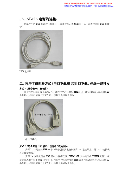
一、AT-12A电源线连接:
将配件中的USB电源线(如图),一端连接学习板USB口,另一端连接电脑USB口即可。
USB电源线
二、程序下载两种方式(串口下载和USB口下载,任选一即可):
方式1(适合有串口的电脑):
直接将串口线连接电脑后,在下载程序里选择对应com端口下载烧录程序(冷启动STC 单片机:点击电脑端“下载”后,再打开学习板电源);
串口下载线
方式2(适合只有USB接口,没有串口的电脑):
步骤1:将配套的USB转串口线分别接到电脑和图1串口连接线上,图1串口连接线再连接学习板。
步骤二:安装光盘内USB转串口驱动程序(CH341SER文件夹下的SETUP文件),在资源管理器中记下com口端号,在下载程序里选择对应com端口下载烧录程序(冷启动STC 单片机:点击电脑端“下载”后,再打开学习板电源);
记下设备管理器中的COM端口号(注意:你的电脑可能不是显示COM7而是COM8或其他,记下你的端口号)
在STC下载程序里选择对应的COM口即可(自己电脑显示的COM端口号)。
高压开关柜(KYN28-12A)使用说明书
D、防止在带电时误合接地开关。(只有在断路器分闸状态或手车退至试验位置,才能合上接地开关)
E、防止误入带电室。(只有隔室不带电时,才能开门进入隔室)
5.5 压力释放装置
元器件使用.同时由于整个柜体用敷铝锌板相拼联,这样使整个柜体都处在良好接地状态之中,确保运行操作人员及 柜体安全。
六 基础形式
1,开关柜的安装基础的施工应符合"电力建设施工及验收技术规范"中的有关条款规定。 2,开关柜的安装基础一般要分二次浇灌混凝土.第一次为开关柜安装构件即角钢或方钢,槽钢构件安装基础,第 二次浇灌混凝土是地面的补充层,一般厚度为 60mm,在浇注混凝土补充层时混凝土高度应低于构件平面 1~3mm。
5.7 带电显示装置
开关柜内设有带电显示装置.该装置由高压传感器和可携带式显示器两部分组成.传感器安装在母线或馈线侧, 显示器的插接口安装在开关柜低压隔室上,当需检测 A,B,C 三相是否带电时,可将携带式显示器的插头插入 L1,L2,L3 接口,如果显示器动作,则表示母线或馈线侧带电,反之,则说明不带电.同时也能作为相序检测器或电光 指示器,其作用也是检测高压侧上是否带电,为了安全,若电缆室装有电缆或互感器,则带电显示上必须装有电磁
单位
VS1-12
VS1-12
VS1-12
VS1-12
kV
12
A
630
1250
2000
3150
Hz
50
kA
25
31.5
40
50
kA
63
80
NEMA 12转换套件安装说明书
Table 3-1: Instructions for NEMA Type 12 Kit Installation — Frame 4 . . . . . . . . . 3-1 Table 3-2: Instructions for NEMA Type 12 Kit Installation — Frame 5 . . . . . . . . . 3-4 Table 3-3: Instructions for NEMA Type 12 Kit Installation — Frame 6 . . . . . . . . . 3-7 Table 4-1: NEMA Type 12 Kit — Dimensions and Weight . . . . . . . . . . . . . . . . . . . 4-1
NEMA 12 Conversion Kit for 9000X Adjustable Frequency Drive
Installation Manual
New Information January 2004
MN04003011E
For more information visit:
This symbol indicates high voltage. It calls your attention to items or operations that could be dangerous to you and other persons operating this equipment. Read the message and follow the instructions carefully.
CAUTION
Indicates a potentially hazardous situation which, if not avoided, can result in minor to moderate injury, or serious damage to the product. The situation described in the CAUTION may, if not avoided, lead to serious results. Important safety measures are described in CAUTION (as well as WARNING).
LP12A规格书
图4. (1)上电 (2)正常工作 (3)自动重启 (4)电源关断时的典型波形
脉宽调制器 脉宽调制器通过驱动输出MOSFET来实现多模式控制,其占空比与流入控制脚超过芯片内部消 耗所需要的电流成反比(如图3)。反馈误差信号以过电流的形式, 由一个典型转折频率为 7 kHz的RC滤波电路进行滤波,以降低芯片电源电流中由MOSFET栅极驱动产生的开关噪音。 要优化电源效率,需要实施四个不同的控制模式。在最大负载条件下,调制器将在全频PWM 模式下进行工作,随着负载的增加,调制器将自动依次切换到变频PWM模式和低频PWM模式。 在轻负载条件下,控制方式将从PWM控制切换到多周期调制控制,调制器在多周期调制模式 下进行工作。虽然不同模式的工作方式有所不同,但为了实现模式间的平滑切换,图3中所
振荡器和开关频率 内部振荡器使内部电容在两个设定的电压值间线性充放电,以产生脉宽调制解调器所需的三 角波电压。在每个周期的起点,振荡器将脉宽调制解调器/电流限制的触发器电路置位。全 开关频率选择为66kHz。全频PWM模式下,66kHz开关频率大约在±2.5kHz的范围内以250Hz 的速率抖动。当系统进入固定漏极峰值电流的变频模式后,频率抖动将关闭。
图 2. 内部结构框图
引脚功能描述
管脚 1
5,6,7,8 3 4 2
符号 S D C NC M
管脚定义描述 功率管的源极 功率管的漏极 控制反馈引脚 空脚,不连接 多功能引脚
控制(C)引脚: 误差放大器及反馈电流的输入脚,用于占空比控制。与内部并联调整器相连接,提供正常工 作时的内部偏置电流。也用作电源旁路和自动重启动/补偿电容的连接点。 漏极(D)引脚: 高压功率MOSFET漏极引脚。通过内部的开关高压电流源提供启动偏置电流。 源极(S)引脚: 这个引脚是功率MOSFET的源极连接点,用于高压功率的回路。它也是控制反馈脚的参考地。 空脚(NC)引脚: 该脚为空脚,与芯片内部无连接,外部应用无需连接。 多功能(M)引脚: 是过压(OV)、欠压(UV)、降低DCMAX的线电压前馈、输出过压保护(OVP)、外部流限调节、远 程开/关和器件重置的输入引脚。多功能引脚组合了电压监测及外部流限引脚功能。但其中 某些功能不能同时实现。连接至源极则禁用此引脚的所有功能实现简单的三端模式工作。
邦健IE12A心电图机操作流程

退出患者 信息界面 信息后系 统自动采 集信息
心电波形 采集完成 后点击“冻 结”(红圈 内)
冻结后点 击“报告” (红圈内)
点击“普通 报告”选项
系统自动 分析并保 存心电图 ቤተ መጻሕፍቲ ባይዱ息,心 电图采集 完成
点击“打印” 即可打印 心电图报 告
点击绿色 按钮可快 速分析打 印心电图, 但不保存 分析结果, 事后记得 保存
邦健IE12A心电图机操作流程
慧博源医院 胡俊骅
心电图机操作顺序
准备 开机 记录 打印 关机
开机前准备
电源连接:使用交流电(220V)或可 以使用本机内安装的充电电池。
检查记录纸是否充足。
检查周围环境舒适,温湿度适宜,周围 环境中无X光机、超声波装置或其他 电 器设备等产生干扰。
导联的连接 将随机附件的 导联线接到机器导联插座。 电极安装 电极的安装是能 否记录准确的心电图的重要 一环,请注意确保电极接触 良好。将电极连接病人时, 务必使电源开关处于关闭状 态。
开机:
打开左侧电源开关, 然后按面“ON/OFF” 键,液晶显示屏显 示整机工作状态及 预设的导联波形。
→
橙色按钮为电 源开关键,同 时也是开关机 键
点击箭头所 指区域,进 入输入患者 信息界面
输入患者 信息界面 信息输入 完成后点 击右上角 “X”即可退 出
输入患者 信息界面 信息输入 完成后点 击右上角 “X”即可退 出
四肢电极连接 电极应装 于两手脚的柔软皮肤上。 先用酒精清洗电极安装部 位的皮肤。然后在清洗后 的皮肤上涂少量的导电膏。
肢体导联:右手:红(R) 左手:黄(L) 左脚:(F) 右脚:黑(N)
肢体导联
心电图检查胸前导联的位置: V1 胸骨右缘第四肋间 V2 胸骨左缘第四肋间 V3 V2与V4连接的中点 V4 左侧锁骨中线第五肋间 V5 左侧腋前线第五肋水平处 V6 左侧腋中线第五肋V5水平
12A安装手册介绍
安装手册LMS bRev 12A 〇.本手册是软件基本安装过程,如有特殊要求,请参考安装光盘中的PDF文件。
一.安装准备工作在安装b软件前,需要准备好b安装光盘,硬件加密狗Dongle,加密文件LMS_NO_SERVER.lic(若文件名不符,请联系LMS工程师)。
安装电脑需要有管理员权限。
二.将光盘放入光盘驱动器,让光盘自动运行或者点击Autorun.exe文件。
三.弹出如下菜单,安装b软件。
点击Install LMS b now…。
安装需要.NETframework,请等待软件安装。
四.在b安装前,首先会自动运行安装LMS Unit System。
1.点Next,开始安装。
2.选择I accept,点Next3.默认设置,点Next4.选择LMS Unit System安装路径,点Next5.选择配置文件路径,点Next6.点Install进行安装。
五.LMS Unit System安装结束后,会自动进行b软件的安装1.点Next2.选择I accept,点Next3.默认设置,点Browse…指定License文件存放路径。
点Next4.选择中间一项:Usea LMS_MID.lic文件,点Browse…指定License文件,点Next5.选择Desktop类型,点Next。
可以用文本编辑软件打开License文件,查找Desktop,确认是Standard版本还是Advanced 版本,再进行安装。
请注意:如果桌面类型选择有误,会造成软件无法使用,需要卸载重新安装。
6.防火墙设置,建议选Yes,点Next7.选择安装路径,点Next8.选择配置文件保存路径,点Next9.默认设置,点Next10.点Install进行安装。
11.软件安装完成12.安装硬件加密狗驱动程序。
两种方法:●安装好b软件后,从开始-> 所有程序->LMS b-> Tools->Licensing, 运行“flexid”和“hdd32”两个文件。
SRJK-12A(18A)系列智能无功补偿控制器(控制接触器2014版本)(1)
SRJK-12A/18A系列智能无功补偿控制器使用说明书引言诚挚的感谢您选用了苏容电气的产品。
请您在安装使用本产品之前详细的阅读本手册,以免造成误操作。
这将为您节约宝贵的时间。
由于产品升级、版本更新,本手册所述内容可能无法完全涵盖。
如有错误、遗漏等不当之处,敬请各位用户谅解。
目录一、产品概述 (4)二、使用条件 (4)三、型号说明 (4)四、产品外形及安装尺寸 (4)五、基本功能 (4)(一)显示功能 (5)(二)设置功能 (5)(三)无功补偿功能 (5)(四)保护功能 (5)(五)超限及故障警示功能 (6)六、技术参数 (6)1. 基本参数 (6)2. 控制参数 (6)3. 测量精度 (7)七、安装调试 (7)1.安全提示 (7)2.安装与接线 (8)3.调试说明 (9)八、开箱检查 (16)九、简单故障排除 (17)一、产品概述本产品符合《JB/T9663-1999》标准。
其人机界面采用大屏幕LCD中文液晶显示器,并集先进的单片机技术为核心。
其安装操作方便,适用于交流0.4KV、50Hz低压配电系统无功补偿控制。
该控制器具有实时监测电网各项参数、谐波保护、无功补偿、及保护警示等功能。
二、使用条件海拔高度:≤2500米环境温度:-20℃- +70℃相对湿度:40℃时20%-90%大气压力:79.5Kpa-106KPa环境条件:周围介质无爆炸危险,无足以损坏绝缘及腐蚀金属的气体,无导电尘埃,安装地不易剧烈振动,无雨雪侵蚀。
三、型号说明SR JKF -- XX AA:接触器输出路数12或者18F:取3相电流(混合补偿型), G:取1相电流(全共补型)苏容电气以上型号只在产品标牌中体现;四、产品外形及安装尺寸SRJK系列无功功率自动补偿控制器为嵌入式安装。
外形尺寸:140mm×140mm×90mm安装开孔尺寸:138mm×138mm安装嵌入深度:72mm五、基本功能1)显示功能采用低功耗LCD液晶中文显示屏,可实时显示A相、B相、C相功率因数、电压、电流、无功、有功、频率、谐波电压、谐波电流、电容器投切状态和故障警示等电网参数,工作状态等。
海尔 DE12A 家用智能除湿机 使用说明书
1. 除湿机不应在湿度设定高于环境湿度的状况下运作。 2. 当水满指示灯亮时,将水箱中的水倒出。然后将清空后的水箱放回原来的位置,机器
就可以继续使用。 3. 当机器停止时,至少需等3分钟才能重新启动,以免压缩机损坏。 4. 可使用的环境温度范围为5-32度。 5. 插头
മ
䘎㔝ᧂ≤
1. ᖃᛘᜣ֯⭘↔࣏㜭ᰦˈ䈧ࠪ≤㇡ˈᨂ≤ᧂޕ
㇑Ҿ“ 䘎㔝ࠪ≤ਓ”(䈧㿱മ 02)ԓᴯ≤㇡ˈሶ
≤㇡᭮എᶕⲴս㖞DŽণ㜭֯⭘↔࣏㜭DŽ
2. ≤㇑享վҾ“ 䘎㔝ࠪ≤ਓ”ԕ≤ׯ㜭亪Ⲵᧂ
ࠪDŽ
മ
ਆࠪ䗷└㖁
1. ਆࠪ䗷└㖁ѻࡽˈሶ≤㇡ਆࠪDŽ 2. ሶ└㖁ᢺੁлࠪDŽ 3. ⇿єઘሶ└㖁ਆࠪ⭘≤(վҾ 40 ᓖ)⍇ˈ
装箱清单 & 规格参数
装箱清单
1. 整机(1 台) 2. 说明书(1 份)
规格参数
රਧ 㿴Ṭ 仍ᇊ⭥৺仁⦷ 儈䲔⒯䟿(30ć RH80%) 仍ᇊ䲔⒯䟿 仍ᇊ䗃⦷࣏ޕ ᴰབྷ䗃⦷࣏ޕ ߰䟽 ቪረ ∛㊣ 䘲⭘⧟ຳġ ≤㇡ᇩ䟿ġ
DE12A
220V~50Hz˄অ˅ 12 ॷ/ᰕ 0.23kg/h 162W 260W 11.2kg
362Wx220D x508H 5ć-32ć 2.2L
(CE) N 842/2006: R134a ᱟӜ䜭䇞ᇊҖѝ㿴㤳Ⲵа⿽≏ॆᇔ≄փ 䈕≄փⲴᙫᇔ᭸ᓄ▌㜭٬(GWP)ᱟ 1430.
2
ܱՊᦊ͈Րሦឭ 1. ᧗ࡦਠ 2. ࠪ仾ਓ 3. ᢺ 4. ࡽ༣
定时键可以显示关机时间)。
ຳएࠀ
※(湿度设定)键:设定所需要的湿度。湿度设定依次为:“CO”
12A硒鼓加粉图解
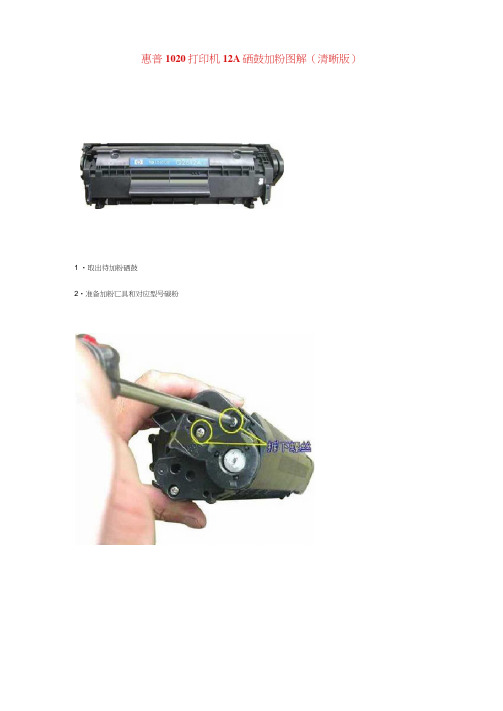
惠普1020打印机12A硒鼓加粉图解(清晰版)
1 •取出待加粉硒鼓
2•准备加粉匸具和对应型号碳粉
5•分离粉仓与废粉仓活理废粉:将废粉收集件中淡蓝色感光鼓两側的金屈定位销拨出,取出感光鼓于阴暗平稳处.拿出放电矩再将刮板上的两个镣钉旋下•移去刮板,慢慢将废粉仓内废粉倒出.再把刮扳、放电規、感光鼓按原來位置复原(如需更换鼓芯、刮板此时将旧鼓芯、刮板换成新的即可)。
6・卸下侧盖灌装墨粉:将供粉件上磁眾无齿轮一侧的怨钉旋下.拿下塑料壳后可看到一个白色塑料盖. 打开此盖•将粉仓内和磁規上的墨粉全部清理干冷(如果不清理踊仏和粉仓打卬样张可能出现底灰或字迹发浅)•将磁轮装好•此时应用力按住≡⅞!t防止磁規脱离丿京位。
把激光打印机墨粉摇匀后慢慢倒入供粉仓内,盖好塑料盖,上好塑料壳(此时应注总:磁擁中轴末端上的半圆形与塑料壳上的半圆形小孔对好)• 轻轻转动磁觇侧而的齿轮数圈,使墨粉上匀C
7・卸下加粉胶盖加入相应型号的碳粉。
将供粉件和废粉收集件按拆开时位宜安装复原.插好两侧金屈卡销。
硒鼓装好后,应推开感光鼓挡板.向上轻转鼓芯侧面齿轮数圈,鼓面残留墨粉即被清除,装机即
可使用。
?复原硒鼓加粉完毕。
注总爭顶:
(I)X纸面上出现有规律的黑点•证明感光鼓已损坏•应及时见换。
(2)所加墨粉应为纯正激光机墨粉.否则会缩短硒鼓使用时间,同时污染机器。
哭多姆DR24D12系列单相交流固态继电器(12A) 用户手册说明书
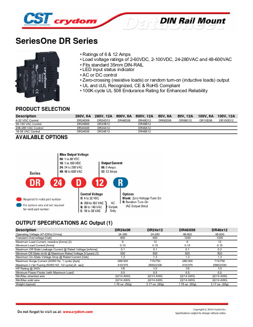
DR06D06
1-60 6 2.5 0.1 0.6 60 0.1
22/14 AWG 22/14 AWG 1.76 oz. (50g)
DR10D06
1-100 6 2.5 0.1 0.6 60 0.1
22/14 AWG 22/14 AWG 1.76 oz. (50g)
280V, 12A
DR24D12 DR24B12 DR24A12 DR24E12
600V, 6A
DR48D06
600V, 12A
DR48D12 DR48B12 DR48A12 DR48E12
60V, 6A
DR06D06
60V, 12A 100V, 6A 100V, 12A
DR06D12
Hale Waihona Puke DR10D06 DR100D12
OUTPUT SPECIFICATIONS DC Output (1)
Description
Operating Voltage [VDC] Maximum Load Current [Adc] (2) Minimum Load Current [mAdc] Maximum Off-State Leakage Current @ Rated Voltage [mA] Maximum On-State Voltage Drop @ Rated Current [Vpk] Maximum Surge Current (10ms) [Apk] On-State resistance at rated current [Ohms] Min/Max stranded wire Min/Max solid wire Weight (typical)
Envision H712a 用户手册说明书

Envision H712a User’s ManualTABLE OF CONTENTSFOR YOUR SAFETY --------------------------------------------------1 SAFETY PRECAUTIONS --------------------------------------2SPECIAL NOTES ON LCD MONITORS -------------------3 BEFORE YOU OPERATE THE MONITOR ---------------------3 FEATURES --------------------------------------------------------3PACKING LIST ---------------------------------------------------3INSTALLATION INSTRUCTIONS ---------------------------4CONTROLS AND CONNECTORS --------------------------5ADJUSTING THE VIEWING ANGLE-----------------------6 OPERATING INSTRUCTIONS -------------------------------------7 GENERAL INSTRUCTIONS----------------------------------7HOW TO ADJUST A SETTING ------------------------------9ADJUSTING THE PICTURE -----------------------------10-11PLUG AND PLAY ----------------------------------------------- 12 TECHNICAL SUPPORT(FAQ) ----------------------------------- 13 ERROR MESSAGE & POSSIBLE SOLUTION--------14 APPENDIX --------------------------------------------------------------15 SPECIFICATIONS -----------------------------------------15-16FACTORY PRESET TIMING TABLE ----------------------17CONNECTOR PIN ASSIGNMENT -------------------------18Before operating the monitor, please read this manual thoroughly. This manual should be retained for future reference.FCC Class B Radio Frequency Interference Statement WARNING: (FOR FCC CERTIFIED MODELS)NOTE: This equipment has been tested and found to comply with the limits for a Class B digital device, pursuant to Part 15 of the FCC Rules. These limits are designed to provide reasonable protection against harmful interference in a residential installation. This equipment generates, uses and can radiate radio frequency energy, and if not installed and used in accordance with the instructions, may cause harmful interference to radio communications. However, there is no guarantee that interference will not occur in a particular installation. If this equipment does cause harmful interference to radio or television reception, which can be determined by turning the equipment off and on, the user is encouraged to try to correct the interference by one or more of the following measures:1.Reorient or relocate the receiving antenna.2.Increase the separation between the equipment and receiver.3.Connect the equipment into an outlet on a circuit different from that towhich the receiver is connected.4.Consult the dealer or an experienced radio/TV technician for help. NOTICE:1.The changes or modifications not expressly approved by the partyresponsible for compliance could void the user's authority to operate the equipment.2.Shielded interface cables and AC power cord, if any, must be used inorder to comply with the emission limits.3.The manufacturer is not responsible for any radio or TV interferencecaused by unauthorized modification to this equipment. It is the responsibilities of the user to correct such interference.As an E NERGY S TAR®Partner our company has determined that this product meets the E NERGY S TAR®guidelines for energy efficiency. WARNING:To prevent fire or shock hazard, do not expose the monitor to rain or moisture. Dangerously high voltages are present inside the monitor. Do not open the cabinet. Refer servicing to qualified personnel only.PRECAUTIONS●Do not use the monitor near water, e.g. near a bathtub, washbowl,kitchen sink, laundry tub, swimming pool or in a wet basement.●Do not place the monitor on an unstable cart, stand, or table. If themonitor falls, it can injure a person and cause serious damage to the appliance. Use only a cart or stand recommended by the manufacturer or sold with the monitor. If you mount the monitor on a wall or shelf, use a mounting kit approved by the manufacturer and follow the kit instructions.●Slots and openings in the back and bottom of the cabinet are provided forventilation. To ensure reliable operation of the monitor and to protect it from overheating, be sure these openings are not blocked or covered. Do not place the monitor on a bed, sofa, rug, or similar surface. Do not place the monitor near or over a radiator or heat register. Do not place the monitor in a bookcase or cabinet unless proper ventilation is provided.●The monitor should be operated only from the type of power sourceindicated on the label. If you are not sure of the type of power supplied to your home, consult your dealer or local power company.●The monitor is equipped with a three-pronged grounded plug, a plug witha third (grounding) pin. This plug will fit only into a grounded power outletas a safety feature. If your outlet does not accommodate the three-wire plug, have an electrician install the correct outlet, or use an adapter to ground the appliance safely. Do not defeat the safety purpose of the grounded plug.●Unplug the unit during a lightening storm or when it will not be used forlong period of time. This will protect the monitor from damage due to power surges.●Do not overload power strips and extension cords. Overloading can resultin fire or electric shock.●Never push any object into the slot on the monitor cabinet. It could shortcircuit parts causing a fire or electric shock. Never spill liquids on the monitor.●Do not attempt to service the monitor by yourself; opening or removingcovers can expose you to dangerous voltages and other hazards. Please refer all servicing to qualified service personnel.●To ensure satisfactory operation, use the monitor only with UL listedcomputers which have appropriate configured receptacles marked between 100 - 240V AC, Min. 5A.●The wall socket shall be installed near the equipment and shall be easilyaccessible.SPECIAL NOTES ON LCD MONITORSThe following symptoms are normal with LCD monitor and do not indicate a problem.NOTES∙Due to the nature of the fluorescent light, the screen may flicker during initial use. Turn off the Power Switch and then turn it on again to make sure the flicker disappears.∙You may find slightly uneven brightness on the screen depending on the desktop pattern you use.∙The LCD screen has effective pixels of 99.99% or more. It may include blemishes of 0.01% or less such as a missing pixel or a pixel lit all of the time.∙Due to the nature of the LCD screen, an afterimage of the previous screen may remain after switching the image when the same image has been displayed for a long time. The monitor will slowly recover from this. BEFORE YOU OPERATE THE MONITORFEATURES∙43.2cm(17”) TFT Color LCD Monitor∙Crisp, Clear Display for Windows∙Recommened Resolutions: 1280X 1024 @60Hz∙EPA E NERGY S TAR®∙Ergonomic Design∙Space Saving, Compact Case DesignCHECKING THE CONTENTS OF THE PACKAGEThe product package should include the following items:1.LCD Monitor2.Owner's Manual3.Power Cord4.D-Sub Cable5.Audio CableINSTALLATION INSTRUCTIONSInstall RemoveFigure 1 Installing and Removing the Swivel BasePOWER CORDPower Source:1.Make sure that the power cord is the correct type required in your area.2.This LCD monitor has an External universal power supply that allowsoperation in either 100/120V AC or 220/240V AC voltage area (No user adjustment is required.)3.Connect the power cord into your LCD monitor’s power input socket, andthen plug the other end into a 3-pin AC power outlet. The power cord may be connected to either a wall power outlet or the power outlet socket on your PC, depending on the type of power cord supplied with your LCD monitor.NOTESA certified power supply cord has to be used with this equipment. The relevant national installation and/or equipment regulations shall be considered. A certified power supply cord not lighter than ordinary polyvinyl chloride flexible cord according to IEC 60227 (designation H05VV-F 3G 0.75mm2 or H05VVH2-F2 3G 0.75mm2) shall be used. Alternative a flexible cord be of synthetic rubber according to IEC 60245 (designation H05RR-F 3G 0.75mm2) shall be used.CONTROLS AND CONNECTORSVIDEO CABLEConnecting the D-Sub Cable: Connect one end of the 15-pin D-Sub cable to the back of the monitor and connect the other end to the computer’s D-Sub port.Connecting the Power Cord:Connect the power cord into your LCD monitor’s power input socket, and then plug the other end into a 3-pin AC power outlet. The power cord may be connected to either a wall power outlet or the power outlet socket on your PC, depending on the type of power cord supplied with your LCD monitor.Caution: If the AC outlet is not grounded (with three holes), install the proper grounding adapter (not supplied).Connecting the Audio Cable:Plug audio cable between the computer multi-media (or sound) card's audio output and monitor's audio input.Figure 2 Connecting Cables1.AC Power Cord2.D-Sub Cable3.Audio CableADJUSTING THE VIEWING ANGLE∙For optimal viewing it is recommended to look at the full face of the monitor, then adjust the monitor’s angle to your own preference.∙Hold the stand so you do not topple the monitor when you change the monitor’s angle.∙You are able to adjust the monitor’s angle from -5︒ to 20︒.Figure 3NOTES∙Do not touch the LCD screen when you change the angle. It may cause damage or break the LCD screen.∙Careful attention is required not to catch your fingers or hands when you change the angle.OPERATING INSTRUCTIONSGENERAL INSTRUCTIONSPress the power button to turn the monitor on or off. The other control buttons are located on the front panel of the monitor (See Figure 4). By changing these settings, the picture can be adjusted to your personal preferences.∙The power cord should be connected.∙Connect the video cable from the monitor to the video card.∙Press the power button to turn on the monitor position. The power indicator will light up.Figure 4 External Control ButtonEXTERNAL CONTROLS1.Auto Adjust Key/Exit 4.>/ Volume2.</ Volume 5.MENU/ENTER3.Power Key/ LEDFRONT PANEL CONTROL∙Power Button / Power Indicator:Press this button to turn the monitor ON or OFF.Blue—Power On mode.Orange—Off mode.∙MENU / ENTER :Activate OSD menu when OSD is OFF or activate/de-activate adjustment function when OSD is ON or Exit OSD menu when in Volume Adjust OSD status.∙> /Volume:Activates the volume control when the OSD is OFF or navigate through adjustment icons when OSD is ON or adjust a function when function is activated.∙< /Volume:Activates the volume control when the OSD is OFF or navigate through adjustment icons when OSD is ON or adjust a function when function is activated.∙Auto Adjust button / Exit:1.When OSD menu is in active status, this button will act as EXIT-KEY(EXIT OSD menu).2.When OSD menu is in off status, press this button for 2 seconds toactivate the Auto Adjustment function.The Auto Adjustment function is used to set the HPos, VPos, Clock and Focus.OSD Lock Function:To lock the OSD, press and hold the MENU button while the monitor is off and then press power button to turn the monitor on. To un-lock the OSD - press and hold the MENU button while the monitor is off and then press power button to turn the monitor on. NOTES∙Do not install the monitor in a location near heat sources such as radiators or air ducts, or in a place subject to direct sunlight, or excessive dust or mechanical vibration or shock.∙Save the original shipping carton and packing materials, as they will come in handy if you ever have to ship your monitor.∙For maximum protection, repackage your monitor as it was originally packed at the factory.∙To maintain the cleanness of your LCD display, wipe it periodically with clean and soft cloth. The screen may be damaged by any liquid splash.∙To keep the monitor looking new, periodically clean it with a soft cloth.Stubborn stains may be removed with a cloth lightly dampened with a mild detergent solution. Never use strong solvents such as thinner, benzene, or abrasive cleaners, since these will damage the cabinet. As a safety precaution, always unplug the monitor before cleaning it.HOW TO ADJUST A SETTING1.Press the MENU-button to activate the OSD window.2.Press< or > to navigate through the functions. Once the desiredfunction is highlighted, press the MENU-button to activate it. If the function selected has a sub-menu, press < or > again to navigate through the sub-menu functions. Once the desired function is highlighted, press MENU-button to activate it.3.Press< or > to change the settings of the selected function.4.To exit and save, select the exit function. If you want to adjust any otherfunction, repeat steps 2-3.Figure 5 The OSD MessageADJUSTING THE PICTUREThe descriptions for function control LEDSMain Menu Item Main Menu IconSub Menu Item Sub Menu IconDescriptionContrast Contrast from Digital-register.LuminanceBrightnessBacklight AdjustmentFocus Adjust Picture Phase to reduce Horizontal-Line noiseImage SetupClockAdjust picture Clock to reduce Vertical-Line noise.H. Position Adjust the horizontal position of the picture.Image PositionV. PositionAdjust the verticalposition of the picture.Warm N/A Recall Warm Color Temperature from EEPROM.Cool N/A Recall Cool Color Temperature from EEPROM.sRGB N/A Recall sRGB Temperature from EEPROM.User / Red Red Gain from er / Green Green Gain Digital-register.Color Temp.User / BlueBlue Gain from Digital-register.Main Menu ItemMain Menu IconSub Menu Item Sub Menu Icon DescriptionYesN/AAuto Adjust the H/V Position, Focus and Clock of picture.Auto ConfigNoN/ADo not execute Auto Config, return to main menu.H. Position Adjust the horizontal position of the OSD.V. Position Adjust the verticalposition of the OSD.OSD SetupOSD TimeoutAdjust the OSD timeout.Language Language N/A Set OSD language InformationInformatio n N/A Show the resolution, H/V frequency and input port of current input timing.Yes N/A Clear each old status of Auto-configuration.Reset NoN/A Do not execute reset, return to main menu.ExitN/AN/AExit OSDPLUG AND PLAYPlug & Play DDC2B FeatureThis monitor is equipped with VESA DDC2B capabilities according to the VESA DDC STANDARD. It allows the monitor to inform the host system of its identity and, depending on the level of DDC used, communicate additional information about its display capabilities.The DDC2B is a bidirectional data channel based on the I²C protocol. The host can request EDID information over the DDC2B channel.THIS MONITOR WILL APPEAR TO BE NON-FUNCTIONAL IF THERE IS NO VIDEO INPUT SIGNAL. IN ORDER FOR THIS MONITOR TO OPERATE PROPERLY, THERE MUST BE A VIDEO INPUT SIGNAL.This monitor meets the Green monitor standards as set by the Video Electronics Standards Association (VESA) and/or the United States Environmental Protection Agency (EPA) and The Swedish Confederation Employees (NUTEK). This feature is designed to conserve electrical energy by reducing power consumption when there is no video-input signal present. When there is no video input signal this monitor, following a time-out period, will automatically switch to an OFF mode. This reduces the monitor's internal power supply consumption. After the video input signal is restored, full power is restored and the display is automatically redrawn. The appearance is similar to a "Screen Saver" feature except the display is completely off. The display is restored by pressing a key on the keyboard, or clicking the mouse.TECHNICAL SUPPORT (FAQ)Problem & Question Possible SolutionPower LED is not on*Check if the Power Switch is in the ON position*Power Cord should be connectedNo Plug & Play *Check if the PC system is Plug & Playcompatible*Check if the Video Card is Plug & Play compatible*Check if the D-15 plug pin of Video Cable is bentPicture is fuzzy *Adjust the Contrast and BrightnessControls.Picture bounces or a wave pattern is present in the picture *Move electrical devices that may cause electrical interference.The power LED is ON but there’s no video or no picture.*Computer Power Switch should be in the ON position.*Computer Video Card should be snugly seated in its slot.*Make sure monitor’s video cable is properly connected to the computer.*Inspect monitor’s video cable and make sure none of the pins are bent.*Make sure computer is operational by hitting the CAPS LOCK key on the keyboard while observing the CAPS LOCK LED. The LED should either turn ON or OFF after hitting the CAPS LOCK key.Missing one of the primary colors (RED, GREEN, or BLUE)*Inspect the monitor’s video cable and make sure that none of the pins are bent.Screen image is not centered or sized properly.*Adjust pixel frequency (CLOCK) and FOCUS or press hot-key (AUTO).Picture has color defects (white does not look white)*Adjust RGB color or select color temperature.Horizontal or vertical disturbances on the screen *Use win 95/98 shut-down mode Adjust CLOCK and FOCUS or perform hot- key(AUTO-key).CLOCK (pixel frequency) controls the number of pixels scanned by one horizontal sweep. If the frequency is not correct, the screen shows vertical stripes and the picture has not correct width.FOCUS adjusts the phase of the pixel clock signal. With a wrong phase adjustment the picture has horizontal disturbances in light picture.For FOCUS and CLOCK adjustment use “dot-pattern” or win 95/98 shut-down mode pattern.ERROR MESSAGE & POSSIBLE SOLUTIONCABLE NOT CONNECTED :1.Check that the signal-cable is properly connected , If the connector isloose, tighten the connector’s screws.2.Check the signal-cable’s connection pins for damage.MODE NOT SUPPORTED :Your computer has been set to unsuitable display mode ,set the computer to display mode given in the following table (See page17).APPENDIXSPECIFICATIONSDriving system TFT Color LCDLCD Panel Size43.2cm(17.0")Pixel pitch0.264mm( H ) × 0.264mm( V )Video R,G,B Analog InterfaceInput Separate Sync.H/V TTLH-Frequency30kHz – 80kHzV-Frequency55-75HzDisplay Colors16.2M ColorsDot Clock135MHzMax. Resolution1280 × 1024Plug & Play VESA DDC2B TMON Mode≤37WEPA E NERGY S TAR®OFF Mode≤1WInput Connector15-pin D-SubInput Video Signal Analog:0.7Vp-p(standard),75 OHM, PositiveMaximum Screen Size Horizontal : 337.92mmVertical :270.34mmPower Source100~240VAC,50~60HzEnvironmental Considerations Operating Temp: 5° to 35°C Storage Temp.: -20° to 60°C Operating Humidity:10% to 85%Dimension371(W)×380(H)×106.4(D)mm Weight (N. W.) 4.5kg Unit (net)Switch∙Auto Adjust Key∙< / Volume∙> / Volume∙Power Button∙MENUExternal Controls:Functions∙Contrast∙Brightness∙Focus∙Clock∙H. Position∙V. Position∙Auto Config∙Language∙Information∙OSD Setup∙(Warm)Color∙(Cool)Color∙ sRGB∙User Color temperature∙Reset∙ExitAudio Output Rated Power 1.5 W rms(Per channel) Regulatory Compliance FCC,CE,cULusPreset Display ModesSTANDARD RESOLUTION HORIZONTALFREQUENCYVERTICALFREQUENCYDos-mode 720 x 400 31.47kHz70.0Hz640 × 48031.47kHz60.0Hz VGA640 × 48037.50kHz75.0Hz800 × 60037.879kHz60.0Hz SVGA800 × 60046.875kHz75.0Hz1024 × 76848.363kHz60.0Hz1024 × 76856.476kHz70.0Hz XGA1024 × 76860.021kHz75.0Hz1280 × 102464.000kHz60.0Hz SXGA1280 × 102480.000kHz75.0HzCONNECTOR PIN ASSIGNMENT15 - Pin Color Display Signal CablePIN NO.DESCRIPTION PIN NO.DESCRIPTION1.Red 9.+5V2.Green10.Detect Cable3.Blue11.Ground4.Ground12.DDC-Serial Data5.Ground13.H-Sync6.R-Ground14.V-Sync7.G-Ground15.DDC-Serial Clock8.B-Ground。
Honda 12V 辅助插座安装说明书

Publication No.
MII 16426
Issue Date
January 2018
PARTS LIST
(2)
1. Open the left saddlebag lid as shown. • Repeat on the right side.
<Left side>
(1)
(3)
No.
Description
CLIP
SCREW
CLIP SCREW
LEFT INNER COWL
LEFT MIDDLE COWL
15. Remove the right deflector panel, right inner cowl and right middle cowl in the same manner as the left side.
9. Remove the screw as shown. • Repeat on the right side.
<Left side>
SCREW
2 of 7
10. Remove the left deflector panel as shown. <Left side>
13. Remove the clip as shown. <Left side>
WIRE TIE Secure the accessory socket harness to the motorcycle’s harness.
7 of 7
LEFT SADDLEBAG LID
2. Rem ove t he lef t si d e c over as s h own, an d disconnect the negative (-) cable of the battery.
M12 标准环形连接器,线到线,密封,线缆接触电流评级为12A,4个位置,60VAC,镍膜说明书

3-2172097-2M12 Connector, Standard Circular Connectors, Cable-to-Cable, 4 Position, Sealable, Wire & Cable, 12A Contact Current Rating (Max), Power, Nickel10/05/2020 08:19PM | Page 1For support call+1 800 522 6752Connectors > Circular Connectors >Standard Circular ConnectorsContact Current Rating (Max):12 AConnector & Contact Terminates To:Wire & CableSealable:YesNumber of Positions:4Connector System:Cable-to-CableFeaturesProduct Type Features Product Type Connector Connector System Cable-to-Cable SealableYesConnector & Contact Terminates To Wire & Cable Circular Connector Type Receptacle Shell TypeMetalConfiguration Features Number of Positions 4Number of Power Positions 4Contacts Preloaded YesElectrical Characteristics Operating Voltage 60 VACBody Features Shell Plating MaterialNickel3-2172097-2 ACTIVEM12 ConnectorTE Internal #:3-2172097-2M12 Connector, Standard Circular Connectors, Cable-to-Cable, 4 Position, Sealable, Wire & Cable, 12A Contact Current Rating (Max), Power, NickelView on >Shell Plating Material NickelShell Base Material Zinc AlloyCircular Connector Insulation Material Type PAContact FeaturesContact Current Rating (Max)12 AReverse Gender NoCircular Connector Contact Type SocketTermination FeaturesTermination Method to Wire & Cable Screw TerminalMechanical AttachmentMating Alignment Type KeyedHousing FeaturesCircular Connector Shell Size20DimensionsWire Size22 – 16 AWGUsage ConditionsIP Water Sealing Level7IP Dust Sealing Level6Operating Temperature Range-40 – 85 °C, -40 – 85 °C[-40 – 185 °F][-40 –185 °F]Operation/ApplicationCircuit Application PowerShielded YesPackaging FeaturesPackaging Quantity1Product ComplianceFor compliance documentation, visit the product page on >EU RoHS Directive 2011/65/EU Compliant with ExemptionsEU ELV Directive 2000/53/EC Compliant with ExemptionsChina RoHS 2 Directive MIIT Order No 32, 2016Restricted Materials Above ThresholdEU REACH Regulation (EC) No. 1907/2006Current ECHA Candidate List: JUN 2020(209)Candidate List Declared Against: JUN 202010/05/2020 08:19PM | Page 2 For support call+1 800 522 675210/05/2020 08:19PM | Page 3For support call+1 800 522 6752Candidate List Declared Against: JUN 2020 (209)SVHC > Threshold:Pb (3% in Component Part)Article Safe Usage Statements:Do not eat, drink or smoke when using this product. Wash thoroughly afterhandling. Recycle if possible and dispose of the article by following all applicable governmental regulations relevant to your geographic location.Halogen Content Low Halogen - Br, Cl, F, I < 900 ppm per homogenous material. Also BFR/CFR/PVC FreeSolder Process Capability Not reviewed for solder process capabilityProduct Compliance DisclaimerThis information is provided based on reasonable inquiry of our suppliers and represents our current actual knowledge based on the information they provided. This information is subject to change. The part numbers that TE has identified as EU RoHS compliant have a maximum concentration of 0.1% by weight in homogenous materials for lead, hexavalent chromium, mercury, PBB, PBDE, DBP, BBP, DEHP, DIBP, and 0.01% for cadmium, or qualify for an exemption to these limits as defined in the Annexes of Directive 2011/65/EU (RoHS2). Finished electrical and electronic equipment products will be CE marked as required by Directive 2011/65/EU. Components may not be CE marked. Additionally, the part numbers that TE has identified as EU ELV compliant have a maximum concentration of 0.1% by weight in homogenous materials for lead, hexavalent chromium, and mercury, and 0.01% for cadmium, or qualify for an exemption to these limits as defined in the Annexes of Directive 2000/53/EC (ELV). Regarding the REACH Regulation, the information TE provides on SVHC in articles for this part number is based on the latest European Chemicals Agency (ECHA) ‘Guidance on requirements for substances in articles’ posted at this URL: https://echa.europa.eu/guidance-documents/guidance-on-reachStandard Circular Connectors(529)Circular Connector Adapters(2) TE Model / Part #3-2172096-2M12 MALE CABLE CONNECTOR-T-CODING-SHLDCompatible PartsAlso in the Series M12 ConnectorCustomers Also Bought10/05/2020 08:19PM | Page 4For support call+1 800 522 6752TE Model / Part #953653-2HOLDER GUIDE FOR RELAYTE Model / Part #2141029-1FUSE BOX ASSY,HARD WIREDTE Model / Part #965914-1TIMER, RECEPTACLE AND TABTE Model / Part #2112045-2LEAVYSEAL LOCKING SLIDESTE Model / Part #1011-232-0305DEUTSCH DT BACKSHELLSTE Model / Part #9-1625999-3Power Resistors: Aluminum Housed, HSCTE Model / Part #6-2271110-2M12, MALE, A CODE, 12P, PG9 (AU)TE Model / Part #6-2271128-2M12, FEMALE, A CODE, R/A, 12P, PG9 (AU)TE Model / Part #6-2271122-2M12, MALE, A CODE, R/A, 12P, PG9 (AU)TE Model / Part #1-2823591-1RAIL ROOFTOP MIMO LTE ANTENNADocumentsCAD Files3D PDF3DCustomer View ModelENG_CVM_CVM_3-2172097-2_A.2d_dxf.zipEnglishCustomer View ModelENG_CVM_CVM_3-2172097-2_A.3d_igs.zipEnglishCustomer View ModelENG_CVM_CVM_3-2172097-2_A.3d_stp.zipEnglishBy downloading the CAD file I accept and agree to the of use.Terms and Conditions Datasheets & Catalog PagesM8 / M12 Connector System CatalogEnglishProduct SpecificationsApplication SpecificationApplication SpecificationEnglish10/05/2020 08:19PM | Page 5 For support call+1 800 522 6752。
安吉尔2305rob12a里面管路安装教程
安吉尔2305rob12a里面管路安装教程
安吉尔2305rob12a管路安装:
1.先按照包装盒内的操作说明书依次拆开各个零部件的外包装,然后将滤芯对准,依次插入到对应的滤壳内。
注意等滤芯安装完成后,要把滤芯外侧的密封圈挨个放正。
2.先把活性炭与过滤膜的接口拆开,并在空芯内部装入过滤滤芯,然后再重新把后置联接管组合好,最后用手将管道的接口拧紧即可。
3.先取出蓝色的叉子,然后把白色的管道向里按入,注意此时只需对准螺纹的接口缓缓往里伸进就可以了,切记用力过猛。
最后等管子深入到最里面后,听到管道被锁住的声音后即可结束对水三通的安装。
4.先量好净水器的安装位置到水管之间的距离,然后按照同等距离截取相应大小的PE管,接着利用工具器械将PE管的一端与水龙头进行固定,最后将两端的接口处拧紧即可。
5.先把PE管的另一端对准净水器的进水口进行螺旋上调,然后用螺丝对准龙头的插口进行螺旋拧紧,最后把龙头外部的白色套子串入接口固定住。
6.把专门用来排废水的管子接入到废水排放处,然后打开开关按照操作说明书进行首次排污,最后等排出的废水慢慢干净且流动自然后,就可以关闭开关投入使用了。
Noctua NF-S12A PWM 风扇安装说明书

NF-S12A PWM | User Manual安装当把NF-S12A PWM安装在散热器、散热片或其它装置上时,请使用自带的安装配件来进行安装(如风扇夹、专用螺丝等等),请使用这些安装机制来进行安装。
在安装NF-S12A PWM时,你可以使用专用的系统(如果你的系统具有安装风扇的功能)或者是我们提供的安装螺丝、有机硅防振装备等。
为了安装风扇使用硅胶支架。
请先把硅胶支架通过安装孔。
然后把风扇放在硅胶支架上,然后再把他们通过安装孔连接起来。
如果有必要需移除NF-S12A PWM的综合性防振垫,你可以很容易的移除。
连接把NF-S12A PWM 通过连接器连接到你主板上的4-pin PWM 连接头,连接到主板的4-pin PWM时连接头可以使风扇以自动速度运行。
请注意,风扇同样可以与你主板上的3-pin 的风扇控制器连接起来。
当与主板的3-pin 风扇控制器连接之后,NF-S12A PWM 将以全速运行,(除非主板提供的电压是以速度控制为基础的)。
如果你需要使用多个NF-S12A PWM风扇,你可以使用系统提供的y-cable(NA-S YC1)来把多个风扇和一个PWM 风扇控制器连接起来。
使用这种方法的话,你的主板控制器将会把你所有已连接的风扇全部以同种速度运行。
-NF-S12A PWM 的长20厘米的基本电缆以它特有的应用程序帮助你把电缆杂乱问题缩到最小。
如果你想要一根更长一点的电缆的话,就请用我们提供给您的30厘米的加长电缆(NA-S EC1)代替吧。
NF-S12A PWM 的低噪音适配器/转接器(NA-RC6)确保您可以把风扇的速度由每分钟1200转减到每分钟900转。
您既可以使用适配器来把风扇的速度设置为已经确定的每分钟900转(前提是速度控制器已经停止工作了),也可以是在速度控制PWM 过程中超过最大速度每分钟900转。
清洁、维护清洗电脑风扇在长时间使用积累下的灰尘、维持其清洁。
为了保持风扇的最高性能,请务必定期用抹布、微湿的纸巾或者真空空气罐来清理您的风扇。
viper 12A高频变压器使用电路
芯片VIPER12A简介芯片VIPER12A是意法半导体有限公司于2002年出的单片小功率开关电源。
具有固定60kHz的开关频率,芯片的电源电压范围很宽(9V-38V):具有电流控制型PWM调制器;具有滞后特性的欠压、过压、过流及过热保护功能等。
芯片外围电路很简单并具有节能特性。
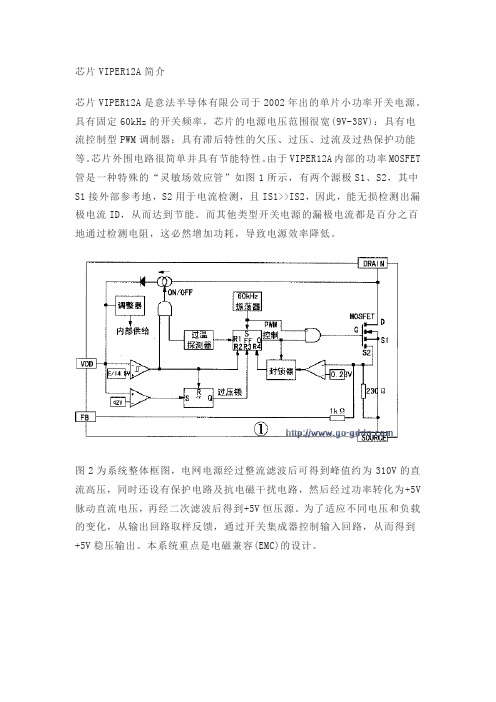
由于VIPER12A内部的功率MOSFET 管是一种特殊的“灵敏场效应管”如图1所示,有两个源极S1、S2,其中S1接外部参考地,S2用于电流检测,且IS1>>IS2,因此,能无损检测出漏极电流ID,从而达到节能。
而其他类型开关电源的漏极电流都是百分之百地通过检测电阻,这必然增加功耗,导致电源效率降低。
图2为系统整体框图,电网电源经过整流滤波后可得到峰值约为310V的直流高压,同时还设有保护电路及抗电磁干扰电路,然后经过功率转化为+5V 脉动直流电压,再经二次滤波后得到+5V恒压源。
为了适应不同电压和负载的变化,从输出回路取样反馈,通过开关集成器控制输入回路,从而得到+5V稳压输出。
本系统重点是电磁兼容(EMC)的设计。
电磁兼容(EMC)设计开关电源是较强的电磁干扰发射源。
这是因为开关电源的整流桥是非线性器件,其形成的电流是严重失真的正弦半波,含有丰富的高次谐波。
同时,功率开关管等半导体元件也会生产电磁干扰。
因此在设计中必须考虑电磁兼容性,主要抑制电磁干扰(EMI)和电磁脉冲(EMP)。
(1)抑制电磁干扰(EMI)电磁干扰(EMI)又叫噪声干扰,要抑制EMI关键是噪声滤波器的设计。
采用噪声滤波器能有效地抑制电网中的噪声进入设备,也可以抑制设备产生的噪声污染电网。
噪声有两种,一种是共模噪声,另一种是差模噪声。
共模噪声产生于相线与大地之间,差模噪声产生于相线之间。
现在使用最多的滤波器是共模电感和电容串接这种类型,其原理如图3所示。
将这个滤波电路一端接干扰源,另一端接被干扰设备,则La和C1,Lb和C2就构成两组低通滤波器,可以使线路上的共模EMI信号被控制在很低的电平上。
- 1、下载文档前请自行甄别文档内容的完整性,平台不提供额外的编辑、内容补充、找答案等附加服务。
- 2、"仅部分预览"的文档,不可在线预览部分如存在完整性等问题,可反馈申请退款(可完整预览的文档不适用该条件!)。
- 3、如文档侵犯您的权益,请联系客服反馈,我们会尽快为您处理(人工客服工作时间:9:00-18:30)。
安装手册
LMS b
Rev 12A 〇.本手册是软件基本安装过程,如有特殊要求,请参考安装光盘中的PDF文件。
一.安装准备工作
在安装b软件前,需要准备好b安装光盘,硬件加密狗Dongle,加密文件LMS_NO_SERVER.lic(若文件名不符,请联系LMS工程师)。
安装电脑需要有管理员权限。
二.将光盘放入光盘驱动器,让光盘自动运行或者点击Autorun.exe文件。
三.弹出如下菜单,安装b软件。
点击Install LMS b now…。
安装需要.NET
framework,请等待软件安装。
四.在b安装前,首先会自动运行安装LMS Unit System。
1.点Next,开始安装。
2.选择I accept,点Next
3.默认设置,点Next
4.选择LMS Unit System安装路径,点Next
5.选择配置文件路径,点Next
6.点Install进行安装。
五.LMS Unit System安装结束后,会自动进行b软件的安装
1.点Next
2.选择I accept,点Next
3.默认设置,点Browse…指定License文件存放路径。
点Next
4.选择中间一项:Usea LMS_MID.lic文件,点Browse…指定License文件,点Next
5.选择Desktop类型,点Next。
可以用文本编辑软件打开License文件,查找Desktop,确认是Standard版本还是Advanced 版本,再进行安装。
请注意:如果桌面类型选择有误,会造成软件无法使用,需要卸载重新安装。
6.防火墙设置,建议选Yes,点Next
7.选择安装路径,点Next
8.选择配置文件保存路径,点Next
9.默认设置,点Next
10.点Install进行安装。
11.软件安装完成
12.安装硬件加密狗驱动程序。
两种方法:
●安装好b软件后,从开始-> 所有程序->LMS b-> Tools->
Licensing, 运行“flexid”和“hdd32”两个文件。
●从安装光盘\Drivers\Licensing Dongle Drivers目录中把加密狗驱动程序拷贝到
电脑上运行。
