CC0402BRNPO9BNR82中文资料
proteus元件对照表经典详细

proteus元件对照表经典详细在电子电路设计与仿真领域,Proteus 软件是一款非常实用的工具。
对于初学者或者经验丰富的工程师来说,了解 Proteus 中的元件及其对应的功能和特性是至关重要的。
本文将为您提供一份详尽且经典的Proteus 元件对照表,帮助您更好地理解和运用这款软件。
一、电阻类元件1、固定电阻(Resistor)常见的封装形式有 0805、0603 等。
电阻值可以通过设置进行调整,单位为欧姆(Ω)。
2、可变电阻(Variable Resistor)也称为电位器(Potentiometer)。
可以通过滑动端改变电阻值,常用于调节电路中的电压或电流。
3、排阻(Resistor Array)多个电阻集成在一个封装内,常见的有 4 引脚和 8 引脚的排阻。
二、电容类元件1、电解电容(Electrolytic Capacitor)有极性,正负极不能接反。
容量通常较大,常用于电源滤波等电路。
2、陶瓷电容(Ceramic Capacitor)无极性。
容量相对较小,稳定性较好。
3、钽电容(Tantalum Capacitor)性能优于电解电容,但价格相对较高。
三、电感类元件1、空心电感(Air Core Inductor)电感量相对较小。
2、铁芯电感(Iron Core Inductor)具有较高的电感量。
3、贴片电感(Chip Inductor)适用于表面贴装技术。
四、二极管类元件1、普通二极管(Diode)具有单向导电性。
2、发光二极管(Light Emitting Diode,LED)通电时会发光,颜色多样。
3、稳压二极管(Zener Diode)能在一定电压范围内保持稳定的电压。
五、三极管类元件1、 NPN 型三极管(NPN Transistor)由三块半导体组成,具有电流放大作用。
2、 PNP 型三极管(PNP Transistor)与 NPN 型三极管工作原理相似,但极性相反。
proteus元件中英文对照
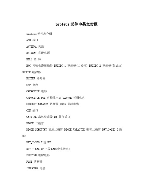
proteus元件中英文对照proteus元件库介绍AND 与门ANTENNA 天线BATTERY 直流电源BELL 铃,钟BVC 同轴电缆接插件 BRIDEG 1 整流桥(二极管) BRIDEG 2 整流桥(集成块) BUFFER 缓冲器BUZZER 蜂鸣器CAP 电容CAPACITOR 电容CAPACITOR POL 有极性电容 CAPVAR 可调电容CIRCUIT BREAKER 熔断丝 COAX 同轴电缆CON 插口CRYSTAL 晶体整荡器 DB 并行插口DIODE 二极管DIODE SCHOTTKY 稳压二极管 DIODE VARACTOR 变容二极管 DPY_3-SEG 3段LEDDPY_7-SEG 7段LEDDPY_7-SEG_DP 7段LED(带小数点)ELECTRO 电解电容FUSE 熔断器INDUCTOR 电感INDUCTOR IRON 带铁芯电感 INDUCTOR3 可调电感 JFET N N沟道场效应管JFET P P沟道场效应管 LAMP 灯泡LAMP NEDN 起辉器LED 发光二极管METER 仪表MICROPHONE 麦克风MOSFET MOS管MOTOR AC 交流电机MOTOR SERVO 伺服电机 NAND 与非门NOR 或非门NOT 非门NPN NPN三极管NPN-PHOTO 感光三极管 OPAMP 运放OR 或门PHOTO 感光二极管PNP 三极管NPN DAR NPN三极管PNP DAR PNP三极管POT 滑线变阻器PELAY-DPDT 双刀双掷继电器 RES1.2 电阻RES3.4 可变电阻RESISTOR BRIDGE ? 桥式电阻 RESPACK ? 电阻SCR 晶闸管PLUG ? 插头PLUG AC FEMALE 三相交流插头SOCKET ? 插座SOURCE CURRENT 电流源 SOURCE VOLTAGE 电压源 SPEAKER 扬声器SW ? 开关SW-DPDY ? 双刀双掷开关 SW-SPST ? 单刀单掷开关 SW-PB 按钮THERMISTOR 电热调节器 TRANS1 变压器TRANS2 可调变压器TRIAC ? 三端双向可控硅 TRIODE ? 三极真空管 VARISTOR 变阻器ZENER ? 齐纳二极管 DPY_7-SEG_DP 数码管 SW-PB 开关protues元件库中英文对照表,对初学者找不到元件的很有用~元件名称中文名说明 7407 驱动门1N914 二极管74Ls00 与非门74LS04 非门74LS08 与门74LS390 TTL 双十进制计数器 7SEG 4针BCD-LED 输出从0-9 对应于4根线的BCD码7SEG 3-8译码器电路BCD-7SEG转换电路ALTERNATOR 交流发电机AMMETER-MILLI mA安培计AND 与门BATTERY 电池/电池组BUS 总线CAP 电容CAPACITOR 电容器CLOCK 时钟信号源CRYSTAL 晶振D-FLIPFLOP D触发器FUSE 保险丝GROUND 地LAMP 灯LED-RED 红色发光二极管LM016L 2行16列液晶可显示2行16列英文字符,有8位数据总线D0-D7,RS,R/W,EN三个控制端口(共14线),工作电压为5V。
IC集成电路型号大全及40系列芯片功能大全

IC集成电路型号大全及40系列芯片功能大全CD4001 四2输入端或者非门CD4002 双4输入端或者非门CD4006 18位串入/串出移位寄存器CD4007 双互补对加反相器CD4008 4位超前进位全加器CD4009 六反相缓冲/变换器CD4010 六同相缓冲/变换器CD4011 四2输入端与非门CD4012 双4输入端与非门CD4013 双主-从D型触发器CD4014 8位串入/并入-串出移位寄存器CD4015 双4位串入/并出移位寄存器CD4016 四传输门CD4017 十进制计数/分配器CD4018 可预制1/N计数器CD4019 四与或者选择器CD4020 14级串行二进制计数/分频器CD4021 08位串入/并入-串出移位寄存器CD4022 八进制计数/分配器CD4023 三3输入端与非门CD4024 7级二进制串行计数/分频器CD4025 三3输入端或者非门CD4026 十进制计数/7段译码器CD4027 双J-K触发器CD4028 BCD码十进制译码器CD4029 可预置可逆计数器CD4030 四异或者门CD4031 64位串入/串出移位存储器CD4032 三串行加法器CD4033 十进制计数/7段译码器CD4034 8位通用总线寄存器CD4035 4位并入/串入-并出/串出移位寄存CD4038 三串行加法器CD4040 12级二进制串行计数/分频器CD4041 四同相/反相缓冲器CD4042 四锁存D型触发器CD4043 三态R-S锁存触发器("1"触发)CD4044 四三态R-S锁存触发器("0"触发)CD4046 锁相环CD4047 无稳态/单稳态多谐振荡器CD4048 四输入端可扩展多功能门CD4049 六反相缓冲/变换器CD4050 六同相缓冲/变换器CD4051 八选一模拟开关CD4052 双4选1模拟开关CD4053 三组二路模拟开关CD4054 液晶显示驱动器CD4055 BCD-7段译码/液晶驱动器CD4056 液晶显示驱动器CD4059 “N”分频计数器 NSC/TICD4060 14级二进制串行计数/分频器CD4063 四位数字比较器CD4066 四传输门CD4067 16选1模拟开关CD4068 八输入端与非门/与门CD4069 六反相器CD4070 四异或者门CD4071 四2输入端或者门CD4072 双4输入端或者门CD4073 三3输入端与门CD4075 三3输入端或者门CD4076 四D寄存器CD4077 四2输入端异或者非门CD4078 8输入端或者非门/或者门CD4081 四2输入端与门CD4082 双4输入端与门CD4085 双2路2输入端与或者非门CD4086 四2输入端可扩展与或者非门CD4089 二进制比例乘法器CD4093 四2输入端施密特触发器CD4095 三输入端J-K触发器CD4096 三输入端J-K触发器CD4097 双路八选一模拟开关CD4098 双单稳态触发器CD4099 8位可寻址锁存器CD40100 32位左/右移位寄存器CD40101 9位奇偶较验器CD40102 8位可预置同步BCD减法计数器CD40103 8位可预置同步二进制减法计数器CD40104 4位双向移位寄存器CD40105 先入先出FI-FD寄存器CD40106 六施密特触发器CD40107 双2输入端与非缓冲/驱动器CD40108 4字×4位多通道寄存器CD40109 四低-高电平位移器CD40110 十进制加/减,计数,锁存,译码驱动CD40147 10-4线编码器CD40160 可预置BCD加计数器CD40161 可预置4位二进制加计数器CD40162 BCD加法计数器CD40163 4位二进制同步计数器CD40174 六锁存D型触发器CD40175 四D型触发器CD40181 4位算术逻辑单元/函数发生器CD40182 超前位发生器CD40192 可预置BCD加/减计数器(双时钟) CD40193 可预置4位二进制加/减计数器CD40194 4位并入/串入-并出/串出移位寄存CD40195 4位并入/串入-并出/串出移位寄存CD40208 4×4多端口寄存器CD4501 4输入端双与门及2输入端或者非门CD4502 可选通三态输出六反相/缓冲器CD4503 六同相三态缓冲器CD4504 六电压转换器CD4506 双二组2输入可扩展或者非门CD4508 双4位锁存D型触发器CD4510 可预置BCD码加/减计数器CD4511 BCD锁存,7段译码,驱动器CD4512 八路数据选择器CD4513 BCD锁存,7段译码,驱动器(消隐) CD4514 4位锁存,4线-16线译码器CD4515 4位锁存,4线-16线译码器CD4516 可预置4位二进制加/减计数器CD4517 双64位静态移位寄存器CD4518 双BCD同步加计数器CD4519 四位与或者选择器CD4520 双4位二进制同步加计数器CD4521 24级分频器CD4522 可预置BCD同步1/N计数器CD4526 可预置4位二进制同步1/N计数器CD4527 BCD比例乘法器CD4528 双单稳态触发器CD4529 双四路/单八路模拟开关CD4530 双5输入端优势逻辑门CD4531 12位奇偶校验器CD4532 8位优先编码器CD4536 可编程定时器CD4538 精密双单稳CD4539 双四路数据选择器CD4541 可编程序振荡/计时器CD4543 BCD七段锁存译码,驱动器CD4544 BCD七段锁存译码,驱动器CD4547 BCD七段译码/大电流驱动器CD4549 函数近似寄存器CD4551 四2通道模拟开关CD4553 三位BCD计数器CD4555 双二进制四选一译码器/分离器CD4556 双二进制四选一译码器/分离器CD4558 BCD八段译码器CD4560 "N"BCD加法器CD4561 "9"求补器CD4573 四可编程运算放大器CD4574 四可编程电压比较器CD4575 双可编程运放/比较器CD4583 双施密特触发器CD4584 六施密特触发器CD4585 4位数值比较器CD4599 8位可寻址锁存器CD22100 4×4×1交叉点开关0206A 天线开关集成电路03VFG9 发射压控振荡集成电路1021AC 发射压控振荡集成电路1097C 升压集成电路140N 电源取样比较放大集成电路14DN363 伺服操纵集成电路15105 充电操纵集成电路15551 管理卡升压集成电路1710 视频信号处理集成电路1N706 混响延时集成电路20810-F6096 存储集成电路2252B 微处理集成电路2274 延迟集成电路24C01ACEA 存储集成电路24C026 存储集成电路24C04 存储集成电路24C64 码片集成电路24LC16B 存储集成电路24LC65 电可改写编程只读存储集成电路27C1000PC-12 存储集成电路27C2000QC-90 存储集成电路27C20T 存储集成电路27C512 电可改写编程只读存储集成电路2800 红外遥控信号接收集成电路28BV64 码片集成电路28F004 版本集成电路31085 射频电源集成电路32D54 电源、音频信号处理集成电路1732D75 电源、音频信号处理集成电路32D92 电源中频放大集成电路4066B 电子开关切换集成电路4094 移位寄存串入、并出集成电路424260SDJ 存储集成电路4260 动态随机存储集成电路4270351/91B9905 中频放大集成电路4370341/90M9919 中频处理集成电路4464 存储集成电路4558 双运算放大集成电路4580D 双运算放大集成电路47C1638AN-U337 微处理集成电路47C1638AU-353 微处理集成电路47C432GP 微处理集成电路47C433AN-3888 微处理集成电路49/4CR1A 中频放大集成电路5101 天线开关集成电路5G052 发光二极管四位显示驱动集成电路5G24 运算放大集成电路5W01 双运算放大集成电路649/CRIA70612 中频放大集成电路673/3CR2A 多模转换集成电路74122 可重触发单稳态集成电路74HC04 逻辑与非门集成电路74HC04D 六反相集成电路74HC123 单稳态集成电路74HC125 端口功能扩展集成电路74HC14N 六反相集成电路74HC157A 多路转换集成电路74HC165 移相寄存集成电路1874HC245 总线收发集成电路74HC32 或者门四2输入集成电路74HC374八D 触发集成电路74HC573D 存储集成电路74HCT157 多路转换双输入集成电路74HCT4046A 压控振荡集成电路74HCT4538D 单稳态集成电路74HCT4538N 触发脉冲集成电路74HCT86D 异或者门四2输入集成电路74HCU04 与非门集成电路74LS125 端口功能扩展集成电路74LS373 锁存集成电路74LS393 计数双四位二进制集成电路74LS74双D 触发集成电路78014DFP 系统操纵处理集成电路811N 伴音阻容偏置集成电路83D33 压控振荡集成电路85712 场扫描信号校正处理集成电路85713 行扫描信号校正集成电路87C52 微处理集成电路87CK38N-3584 微处理集成电路87CK38N-3627 微处理集成电路89C52 系统操纵处理集成电路89C55 系统操纵处理集成电路93C66 电可改写编程只读存储集成电路93LC56 电可改写编程存储集成电路9821K03 系统操纵集成电路A1642P 背景歌声消除集成电路A701 红外遥控信号接收集成电路A7950 场频识别集成电路19A8772AN 色差信号延迟处理集成电路A9109 功率放大集成电路AAB 电源集成电路ACA650 色度信号解调集成电路ACFP2 色度、亮度信号分离集成电路ACP2371 多伴音、多语言改善集成电路ACVP2205 色度、亮度信号分离集成电路AD1853 立体声数/模转换集成电路AD1858 音频解调集成电路AD722 视频编码集成电路ADC2300E 音频数/模转换集成电路ADC2300J 音频数/模转换集成电路ADC2310E 音频数/模转换集成电路ADV7172 视频编码集成电路ADV7175A 视频编码集成电路AE31201 频率显示集成电路AJ7080 射频调制集成电路AK4321-VF-E1 音频数/模转换集成电路AN1319 双高速电压比较集成电路AN1358S 双运算放大集成电路AN1393 双运算放大集成电路AN1431T 稳压电源集成电路AN1452 音频前置放大集成电路AN1458S 双运算放大集成电路AN206 伴音中频及前置放大集成电路AN222 自动频率操纵集成电路AN236 副载波信号处理集成电路AN239Q 图像、伴音中频放大集成电路AN247P 图像中频放大、AGC操纵集成电路AN253P 调频/调幅中频放大集成电路20AN262 音频前置放大集成电路AN2661NK 视频信号处理集成电路AN2663K 视频信号处理集成电路AN272 音频功率放大集成电路AN2751FAP 视频信号处理集成电路AN281 色度解码集成电路AN2870FC 多功能操纵集成电路AN295 行、场扫描信号处理集成电路AN301 伺服操纵集成电路AN305 视频自动增益操纵集成电路AN306 色度自动相位操纵集成电路AN318 直流伺服操纵集成电路AN320 频率操纵、调谐显示驱动集成电路AN3215K 视频信号处理集成电路AN3215S 视频信号处理集成电路AN3224K 磁头信号记录放大集成电路AN3248NK 亮度信号记录、重放处理集成电路AN331 视频信号处理集成电路AN3311K 磁头信号放大集成电路AN3313 磁头信号放大集成电路AN3321S 录像重放信号处理集成电路AN3331K 磁头信号处理集成电路AN3337NSB 磁头信号放大集成电路AN3380K 磁头信号处理集成电路AN3386NK 磁头信号处理集成电路AN3495K 色度、亮度信号降噪集成电路AN355 伴音中频放大、检波集成电路AN3581S 视频驱动集成电路AN366 调频/调幅中频放大集成电路AN3791 移位操纵集成电路21AN3792 磁鼓伺服操纵接口集成电路AN3795 主轴伺服操纵接口集成电路AN3814K 电机驱动集成电路AN4265 音频功率放大集成电路AN4558 运算放大集成电路AN5010 电子选台集成电路AN5011 电子选台集成电路AN5015K 电子选台集成电路AN5020 红外遥控信号接收集成电路AN5025S 红外遥控信号接收集成电路AN5026K 红外遥控信号接收集成电路AN5031 电调谐操纵集成电路AN5034 调谐操纵集成电路AN5036 调谐操纵集成电路AN5043 调谐操纵集成电路AN5071 频段转换集成电路AN5095K 电视信号处理集成电路AN5110 图像中频放大集成电路AN5130 图像中频、视频检波放大集成电路AN5138NK 图像、伴音中频放大集成电路AN5156K 电视信号处理集成电路AN5177NK 图像、伴音中频放大集成电路AN5179K 图像、伴音中频放大集成电路AN5183K 中频信号处理集成电路AN5195K 中频、色度、扫描信号处理集成电路AN5215 伴音信号处理集成电路AN5520 伴音中频放大及鉴频集成电路AN5222 伴音中频放大集成电路AN5250 伴音中频放大、鉴频及功率放大集成电路AN5262 音频前置放大集成电路22AN5265 音频功率放大集成电路AN5270 音频功率放大集成电路AN5273 双声道音频功率放大集成电路AN5274 双声道音频功率放大集成电路AN5275 中置、3D放大集成电路AN5285K 双声道前置放大集成电路AN5295NK 音频信号切换集成电路AN5312 视频、色度信号处理集成电路AN5313NK 视频、色度信号处理集成电路AN5342 图像水平轮廓校正集成电路AN5342FB 水平清晰度操纵集成电路AN5344FBP 色度信号处理集成电路AN5348K 人工智能信号处理集成电路AN5385K 色差信号放大集成电路AN5410 行、场扫描信号处理集成电路AN5421 同步检测集成电路AN5422 行、场扫描信号处理集成电路AN5512 场扫描输出集成电路AN5515 场扫描输出集成电路AN5521 场扫描输出集成电路AN5532 场扫描输出集成电路AN5534 场扫描输出集成电路AN5551 枕形校正集成电路AN5560 场频识别集成电路AN5600K 中频、亮度、色度及扫描信号处理集成电路AN5601K 视频、色度、同步信号处理集成电路AN5607K 视频、色度、行场扫描信号处理集成电路AN5615 视频信号处理集成电路AN5620X 色度信号处理集成电路AN5621 场扫描输出集成电路23AN5625 色度信号处理集成电路AN5633K 色度信号处理集成电路AN5635 色度解码集成电路AN5635NS 色度解码集成电路AN5637 色度解码、亮度延迟集成电路AN5650 同步信号分离集成电路AN5682K 基色电子开关切换集成电路AN5693K 视频、色度、行场扫描信号处理集成电路AN5712 图像中频放大、AGC操纵集成电路AN5722 图像中频放大、检波集成电路AN5732 伴音中频放大、鉴频集成电路AN5743 音频功率放大集成电路AN5750 行自动频率操纵及振荡集成电路AN5757S 行扫描电源电压操纵集成电路AN5762 场扫描振荡、输出集成电路AN5764 光栅水平位置操纵集成电路AN5765 电源稳压操纵集成电路AN5767 同步信号处理集成电路AN5768 光栅倾斜校正操纵集成电路AN5769 行、场会聚操纵集成电路AN5790N 行扫描信号处理集成电路AN5791 同步脉冲相位与脉宽调整集成电路AN5803 双声道立体声解调集成电路AN5836 双声道前置放大集成电路AN5858K 视频信号操纵集成电路AN5862 视频信号操纵集成电路AN5862S-E1 视频信号开关操纵集成电路AN5870K 模拟信号切换集成电路AN5891K 音频信号处理集成电路AN614 行枕形校正集成电路24AN6210 双声道前置放大集成电路AN6306S 亮度信号处理集成电路AN6308 模拟电子开关集成电路AN6327 视频重放信号处理集成电路AN6341N 伺服操纵集成电路AN6342N 基准分频集成电路AN6344 伺服操纵集成电路AN6345 分频集成电路AN6346N 磁鼓伺服操纵集成电路AN6350 磁鼓伺服操纵集成电路AN6357N 主轴接口集成电路AN6361N 色度信号处理集成电路AN6367NK 色度信号处理集成电路AN6371S 自动相位操纵集成电路AN6387 电机伺服操纵集成电路AN6550 卡拉OK音频放大集成电路AN6554 四运算放大集成电路AN6561 双运算放大集成电路AN6562SG 双运算放大集成电路AN6609N 电机驱动集成电路AN6612 电机稳速操纵集成电路AN6650 电机速度操纵集成电路AN6651 电机速度操纵集成电路AN6652 电机稳速操纵集成电路AN6875 发光二极管五位显示驱动集成电路AN6877 发光二极管七位显示驱动集成电路AN6884 发光二极管五位显示驱动集成电路AN6886 发光二极管五位显示驱动集成电路AN6888 发光二极管显示驱动集成电路AN6914 双电压比较集成电路25AN7085N5 单片录、放音集成电路AN7105 双声道音频功率放大集成电路AN7106K 双声道音频功率放大集成电路AN7108 单片立体声放音集成电路AN710S 单片放音集成电路AN7110E 音频功率放大集成电路AN7114 音频功率放大集成电路AN7116 音频功率放大集成电路AN7118 双声道音频功率放大集成电路AN7118S 双声道音频功率放大集成电路AN7120 音频功率放大集成电路AN7124 双声道音频功率放大集成电路AN7145 双声道音频功率放大集成电路AN7148 双声道音频功率放大集成电路AN7158N 音频功率放大7.5W×2集成电路AN7161N 音频功率放大集成电路AN7164 双声道音频功率放大集成电路AN7171NK 音频功率放大集成电路AN7205 调频/调谐及高频放大集成电路AN7220 调频/调幅中频放大集成电路AN7222 调频/调幅中频放大集成电路AN7223 调频/调幅中频放大集成电路AN7226 调频/调幅中频放大集成电路AN7256 调频/调谐及中频放大集成电路AN7311 双声道前置放大集成电路AN7312 双声道前置放大集成电路AN7315 双声道前置放大集成电路AN7315S 双声道前置放大集成电路AN7320 音频前置放大集成电路AN7396K 双声道前置放大集成电路26AN7397K 双声道前置放大集成电路AN7410 调频立体声多路解码集成电路AN7414 调频立体声解码集成电路AN7420N 调频立体声解码集成电路AN7470 调频立体声解码集成电路AN7805 三端电源稳压+5V/1A集成电路AN7806 三端电源稳压+6V/1A集成电路AN7807 三端电源稳压+7V/1A集成电路AN7808 三端电源稳压+8V/1A集成电路AN7809 电源稳压+9V/1A集成电路AN7810 三端电源稳压+10V/1A集成电路AN7812 三端电源稳压+12V/1A集成电路AN7815 三端电源稳压+15V/1A集成电路AN7818 三端电源稳压+18V/1A集成电路AN7820 三端电源稳压+20V/1A集成电路AN7824 三端电源稳压+24V/1A集成电路AN78L05 三端电源稳压+5V/0.1A集成电路AN78L06 三端电源稳压+6V/0.1A集成电路AN78L08 三端电源稳压+8V/0.1A集成电路AN78L09 三端电源稳压+9V/0.1A集成电路AN78L10 三端电源稳压+10V/0.1A集成电路AN78L12 三端电源稳压+12V/0.1A集成电路AN78L15 三端电源稳压+15V/0.1A集成电路AN78L18 三端电源稳压+18V/0.1A集成电路AN78L20 三端电源稳压+20V/0.1A集成电路AN78L24 三端电源稳压+24V/0.1A集成电路AN78M05 三端电源稳压+5V/0.5A集成电路AN78M06 三端电源稳压+6V/0.5A集成电路AN78M08 三端电源稳压+8V/0.5A集成电路AN78M09 三端电源稳压+9V/0.5A集成电路27AN78M10 三端电源稳压+10V/0.5A集成电路AN78M12 三端电源稳压+12V/0.5A集成电路AN78M15 三端固定式稳压+15V/0.5A集成电路AN78M18 三端电源稳压+18V/0.5A集成电路AN78M20 三端电源稳压+20V/0.5A集成电路AN78M24 三端电源稳压+24V/0.5A集成电路AN7905 三端电源稳压-5V/1A集成电路AN7906 三端电源稳压-6V/1A集成电路AN7908T 三端电源稳压-8V/1A集成电路AN7909T 三端电源稳压-9V/1A集成电路AN7910T 三端电源稳压-10V/1A集成电路AN7912 三端电源稳压-12V/1A集成电路AN7915 三端电源稳压-15V/1A集成电路AN7918 三端电源稳压-18V/1A集成电路AN7920 三端电源稳压-20V/1A集成电路AN7924 三端电源稳压-24V/1A集成电路AN79L05 三端电源稳压-5V/0.1A集成电路AN79L06 三端电源稳压-6V/0.1A集成电路AN79L08 三端电源稳压-8V/0.1A集成电路AN79L09 三端电源稳压-9V/0.1A集成电路AN79L10 三端电源稳压-10V/0.1A集成电路AN79L12 三端电源稳压-12V/0.1A集成电路AN79L15 三端电源稳压-15V/0.1A集成电路AN79L18 三端电源稳压-18V/0.1A集成电路AN79L20 三端电源稳压-20V/0.1A集成电路AN79L24 三端电源稳压-24V/0.1A集成电路AN79M05 三端电源稳压-5V/0.5A集成电路AN79M06 三端电源稳压-6V/0.5A集成电路AN79M08 三端电源稳压-8V/0.5A集成电路AN79M09 三端电源稳压-9V/0.5A集成电路28AN79M10 三端电源稳压-10V/0.5A集成电路AN79M12 三端电源稳压-12V/0.5A集成电路AN79M15 三端电源稳压-15V/0.5A集成电路AN79M18 三端电源稳压-18V/0.5A集成电路AN79M20 三端电源稳压-20V/0.5A集成电路AN79M24 三端电源稳压-24V/0.5A集成电路AN8028 自激式开关电源操纵集成电路AN8270K 主轴电机操纵集成电路AN8280 电机驱动集成电路AN8281S 电机驱动集成电路AN8290S 主轴电机驱动集成电路AN8355S 条形码扫描接收集成电路AN8370S 光电伺服操纵集成电路AN8373S 射频伺服处理集成电路AN8375S 伺服处理集成电路AN8389S-E1 电机驱动集成电路AN8480NSB 主轴电机驱动集成电路AN8481SB-E1 主轴电机驱动集成电路AN8482SB 主轴电机驱动集成电路AN8623FBQ 主轴伺服处理集成电路AN8788FB 电机驱动集成电路AN8802CE1V 伺服处理集成电路AN8813NSBS 主轴电机驱动集成电路AN8819NFB 伺服驱动、直流交换集成电路AN8824FBQ 前置放大集成电路AN8825NFHQ-V 聚焦、循迹误差处理集成电路AN8831SC 视频预视放集成电路AN8832SB-E1 射频放大、伺服处理集成电路AN8837SB-E1 伺服处理集成电路AN89C2051-24PC 微处理集成电路29APU2400U 音频信号处理集成电路APU2470 音频信号处理集成电路AS4C14405-60JC 动态随机存储1M×4集成电路AS4C256K16ED-60JC 存储集成电路ASD0204-015 图文操纵集成电路ASD0204GF-022-3BA显示操纵集成电路AT24C08 存储集成电路AT24C08A 存储集成电路AT24C256-10CI 码片集成电路AT27C010 电可改写编程只读存储集成电路AT27C020 存储集成电路ATMEL834 存储集成电路AVM-1 视频信号处理厚膜集成电路AVM-2 音频信号处理厚膜集成电路AVSIBCP08 倍压整流切换集成电路B0011A 存储集成电路B1218 电子快门操纵集成电路BA033T 三端电源稳压+3.3V集成电路BA10324 四运算放大集成电路BA10393N 双运算放大集成电路BA1102F 杜比降噪处理集成电路BA1106F 杜比降噪处理集成电路BA12ST 电源稳压集成电路BA1310 调频立体声解码集成电路BA1332L 调频立体声解码集成电路BA1350 调频立体声解码集成电路BA1351 调频立体声解码集成电路BA1356 调频立体声解码集成电路BA1360 调频立体声解码集成电路BA15218N 双运算放大集成电路30BA225 可触发双单稳态振荡集成电路BA302 音频前置放大集成电路BA311 音频前置放大集成电路BA313 音频前置放大集成电路BA3283 单片放音集成电路BA328F 双声道前置放大集成电路BA329 双声道前置放大集成电路BA3304F 录放音前置均衡放大集成电路BA3306 音频、前置放大集成电路BA3312N 话筒信号前置放大集成电路BA3313L 自动音量操纵集成电路BA3314 话筒信号前置放大集成电路BA335 自动选曲集成电路BA336 自动选曲集成电路BA340 音频前置放大集成电路BA3402F 双声道前置放大集成电路BA3404F 自返转放音集成电路BA343 双声道前置放大集成电路BA3503F 双声道前置放大集成电路BA3506 单片放音集成电路BA3513FS 单片放音集成电路BA3516 单片放音集成电路BA3706 自动选曲集成电路BA3707 录音带曲间检测集成电路BA3812L 五频段音调补偿集成电路BA3818F 电压比较运放集成电路BA3822LS 双声道五频段显示均衡集成电路BA3828 电子选台预置集成电路BA3880 音频处理集成电路31BA401 调频中频放大集成电路BA402 调频中频放大集成电路BA4110 调频中频放大集成电路BA4234L 调频中频放大集成电路BA4402 调频调谐收音集成电路BA4403 调频高频放大、混频、本振集成电路BA4560 双运算放大集成电路BA5096 数字混响集成电路BA5102A 音频功率放大集成电路BA514 音频功率放大集成电路BA516 音频功率放大集成电路BA5208AF 音频功率放大集成电路BA532 音频功率放大集成电路BA534 音频功率放大集成电路BA5406 双声道音频功率放大集成电路BA5412 音频功率放大集成电路BA547 音频功率放大1.5W集成电路BA5912AFP-YE2 电机驱动、倾斜、加载集成电路BA5981FP-E2 聚焦、循迹驱动集成电路BA5983FB 四通道伺服驱动集成电路BA5983FM-E2 电机驱动集成电路BA6104 发光二极管五位显示驱动集成电路BA6107A 电机伺服操纵集成电路BA6109 加载电机驱动集成电路BA6125 发光二极管五位显示驱动集成电路BA6137 发光二极管五位显示驱动集成电路BA6191 音频操纵集成电路BA6196FP 伺服驱动集成电路BA6208 电机驱动集成电路BA6208D 电机驱动集成电路32BA6209 电机驱动集成电路BA6209N 双向驱动电机集成电路BA6218 加载电机驱动集成电路BA6219 电机驱动集成电路BA6219B 电机驱动集成电路BA6227 电机稳速操纵集成电路BA6238 电机驱动集成电路BA6239 电机双向驱动集成电路BA6239A 电机双向驱动集成电路BA6246M 加载、转盘电机驱动集成电路BA6248 电机驱动集成电路BA6286 电机驱动集成电路BA6287 电机驱动集成电路BA6290 电机驱动集成电路BA6295AFP-E2 加载、倾斜驱动集成电路BA6296FP 电机速度操纵集成电路BA6297AFP 伺服驱动集成电路BA6302A 电机伺服操纵集成电路BA6305 操纵放大集成电路BA6305F 操纵放大集成电路BA6308 电子开关切换集成电路BA6321 电机伺服操纵集成电路BA6392 伺服驱动集成电路BA6395 主轴电机驱动集成电路BA6396FP 伺服驱动集成电路BA6411 电机驱动集成电路BA6435S 主轴电机驱动集成电路BA6459P1 电机驱动集成电路BA6570FP-E2 聚焦、循迹驱动集成电路33BA6664FM 三相主电机驱动集成电路BA6791FP 四通道伺服驱动集成电路BA6796FP 电机驱动集成电路BA6810S 音频显示驱动集成电路BA6844AFP-E2 三相主电机驱动集成电路BA6849FP 主轴电机驱动集成电路BA689 发光二极管十二位显示驱动集成电路BA6893KE2 直流变换驱动集成电路BA6956AN 加载电机驱动集成电路BA6993 双运算放大集成电路BA7001 音频切换集成电路BA7004 测试信号发生集成电路BA7005AL 射频调制集成电路BA7007 信号检测集成电路BA7021 视频信号选择集成电路BA7024 视频信号测试集成电路BA7025L 信号检测集成电路BA7042 振荡集成电路BA7047 调频检波集成电路BA7048N 包络信号检测集成电路BA7106LS 检测信号操纵集成电路BA7180FS 磁头信号放大集成电路BA7212S 磁头信号放大集成电路BA7253S 磁头信号放大集成电路BA7254S 四磁头信号放大集成电路BA7258AS 亮度信号处理集成电路BA7264S 视频信号处理集成电路BA7274S 磁头信号放大集成电路BA7357S 中频放大集成电路BA7604N 电子开关切换集成电路34BA7606F 色差信号切换集成电路BA7655 色度信号处理集成电路BA7665FS-E2 视频输出放大集成电路BA7725FS 混响立体声放大集成电路BA7725S 信号压缩及扩展处理集成电路BA7743FS 磁头信号放大集成电路BA7751ALS 音频信号录放处理集成电路BA7752LS 音频信号处理集成电路BA7755 磁头开关集成电路BA7755AF-E2 磁头开关集成电路BA7765AS 音频信号处理集成电路BA7766SA 音频信号处理集成电路BA7767AS 音频信号处理集成电路BA7797F 音频信号处理集成电路BA8420 特技操纵处理集成电路BAL6309 场同步信号发生集成电路BH3866AS 音频、色度信号前置放大集成电路BH4001 微处理集成电路BH7331P 音频功率放大集成电路BH7770KS 音频信号处理集成电路BL3207 亮度延时集成电路BL3208B 音频延迟混响集成电路BL5132 中频放大集成电路BL54573 电子调频波段转换集成电路BL5612 视频放大、色差矩阵集成电路BM5060 微处理集成电路BM5061 字符发生集成电路BM5069 微处理集成电路BN5115 图像中频放大集成电路BOC31F 单片微处理集成电路35BP5020 视频电源转换集成电路BT852 视频编码集成电路BT864 视频编码集成电路BT866PQFP 微处理集成电路BU12102 时序信号发生解码集成电路BU2092F 扩展集成电路BU2185F 同步信号处理集成电路BU2285FV 时钟信号发生集成电路BU2820 伺服操纵集成电路BU2841FS 视频、蓝背景信号发生集成电路BU2872AK 操作系统操纵、屏显驱动集成电路BU3762AF 红外遥控信号发射集成电路BU4053B 电子开关切换集成电路BU5814F 红外遥控信号发射集成电路BU5994F 红外遥控信号发射集成电路BU6198F 屏幕显示集成电路BU9252F 音频延时集成电路BU9252S 数/模转换集成电路BU9253FS 话筒音频混响集成电路BX1303 音频功率放大集成电路BX1409 红外遥控信号接收集成电路BX7506 主轴电机电源操纵集成电路C1363CA 红外遥控电子选台集成电路C1490HA 红外遥控信号接收集成电路C187 分配、十进制计数集成电路C301 译码BCD-10段集成电路C68639Y 微处理集成电路C75P036 微处理集成电路CA0002 调幅模拟声解调集成电路CA2004 音频功率放大集成电路36CA2006 音频功率放大集成电路CA270AW 视频检波放大集成电路CA3075 调频中频放大集成电路CA3089 调频中频放大集成电路CA3120E 视频信号处理集成电路CA3140 运算放大集成电路CA810 音频功率放大集成电路CA920 行扫描信号处理集成电路CAS126 天线开关集成电路CAT24C16 电可改写编程只读存储集成电路CAT35C104HP 存储集成电路CC4000 或者非门双3输入集成电路CC4008 计数4位二进制集成电路CC40107 与非双2输入缓冲、驱动集成电路CC40174 六D触发集成电路CC40194 移位寄存集成电路CC4025 或者非门3输入集成电路CC4026 译码、驱动、十进制计数集成电路CC4027 上升沿J-K触发集成电路。
光纤热缩管分类

器件外径( 后)DeviceO.D.(aftershrink)
60601410 1.4±0.05 1.3±0.1
收缩
0c85f9e 易博
60±1 3.0±0.1mm 3、★单芯石英型 产品特征 符合 RoHS
特殊设计由交联聚烯烃,热熔管和增强型不 锈钢(石英,或陶瓷)构成
光纤接续保护元件,不影响光纤旳光导特征 保护接续点,提升机械强度 操作简朴,降低安装时损伤光纤旳危险
密封构造使接续具有良好旳耐温度、湿度性 能
光纤接续保护元件,不影响光纤旳光导特征 保护接续点,提升机械强度 操作简朴,降低安装时损伤光纤旳危险
密封构造使接续具有良好旳耐温度、湿度性 能
产品编号 PartNo. 钢棒外径(mm)
0c85f9e 易博
SteelRodO.D.(mm) 热熔管内径(mm) FusionTubeI.D.(mm) 热缩管长度(mm) HeatShrinkTubeLength(mm)
操作简朴,降低安装时损伤光纤旳危险 密封构造使接续具有良好旳耐温度、湿度性 能 4、★双陶瓷型 产品特征
符合 RoHS 特殊设计由交联聚烯烃,热熔管和增强型不 锈钢(石英,或陶瓷)构成 光纤接续保护元件,不影响光纤旳光导特征 保护接续点,提升机械强度
0c85f9e 易博
操作简朴,降低安装时损伤光纤旳危险
符合 RoHS 特殊设计由交联聚烯烃,热熔管和增强型不 锈钢(石英,或陶瓷)构成 光纤接续保护元件,不影响光纤旳光导特征 保护接续点,提升机械强度
0c85f9e 易博
操作简朴,降低安装时损伤光纤旳危险 密封构造使接续具有良好旳耐温度、湿度性 能 2、★单石英型 产品特征
符合 RoHS 特殊设计由交联聚烯烃,热熔管和增强型不 锈钢(石英,或陶瓷)构成 光纤接续保护元件,不影响光纤旳光导特征 保护接续点,提升机械强度
Balluff BIS C系列产品说明书

Supply voltage Current consumption Operating temperature range
24V DC±10% 0.35...0.75A(Depends on the number of connectable antenna) 0...+55℃
Connection to ID converter Connection to Host PLC
3 directions variable
41
Product specification Basicsystem / BIS Cseries
Number of connectable antenna Interface Dimension
Processor SerialInterface
1CH (Built in converter) Serial / USB
Remarks
Please request the instruction manual for details about specifications.
Applicable OS:Microsoft Windows2000 and XP Included:Driver CD、USB cable
42
Product specification Basicsystem / BIS Cseries
Number of connectable antenna Interface Dimension
Processor SerialInterface
1CH Serial / RS-232C
Interface
38
1CH (Built-in converter) Serial / RS-232C
FOSAN富信电子 二级管 BAL99-产品规格书

安徽富信半导体科技有限公司ANHUI FOSAN SEMICONDUCTOR TECHNOLOGY CO.,LTD.BAL99SOT-23Switching Diode 开关二极管▉Internal Configuration内部结构▉Features 特点Characteristic 特性参数Symbol 符号Max 最大值Unit 单位Power dissipation 耗散功率P D (Ta=25℃)225mW Forward Current 正向电流I F 200mA Reverse Voltage 反向电压V R 75VJunction and Storage Temperature 结温和储藏温度T J ,T stg-55to+150℃■DeviceMarking 产品打标BAL99=JF■Electrical Characteristics 电特性(TA =25℃unless otherwise noted 如无特殊说明,温度为25℃)Characteristic 特性参数Symbol 符号Min 最小值Max 最大值Unit 单位Reverse Breakdown Voltage 反向击穿电压(I R =100uA)V (BR)75—V Reverse Leakage Current(V R =20V)反向漏电流(V R =75V)I R—252.5nA µA Forward V oltage(I F =1mA)正向电压(I F =10mA)(I F =50mA)(I F =150mA)V F —0.7150.8551.01.25VDiode Capacitance 二极管电容(V R =0V,f=1MHz)C T—2pF Reverse Recovery Time 反向恢复时间T rr—4nSANHUI FOSAN SEMICONDUCTOR TECHNOLOGY CO.,LTD.BAL99■Typical Characteristic Curve典型特性曲线Figure1:Forward Characteristics Figure2:Leakage CurrentFigure3:Capacitance Characteristics Figure4:Power Derating CurveANHUI FOSAN SEMICONDUCTOR TECHNOLOGY CO.,LTD.BAL99■Dimension外形封装尺寸Symbol Dimensions In Millimeters Dimensions In Inches Min Max Min Max A 0.900 1.1500.0350.045A10.0000.1000.0000.004A20.900 1.0500.0350.041b 0.3000.5000.0120.020c 0.0800.1500.0030.006D 2.800 3.0000.1100.118E 1.200 1.4000.0500.055E1 2.2502.5500.0890.100e 0.950TYP0.037TYPe1 1.8002.0000.0710.079L 0.550REF0.022REFL10.3000.5000.0120.020θ0o8o 0o8o。
SIBA URB 系列半导体保护熔断器说明书
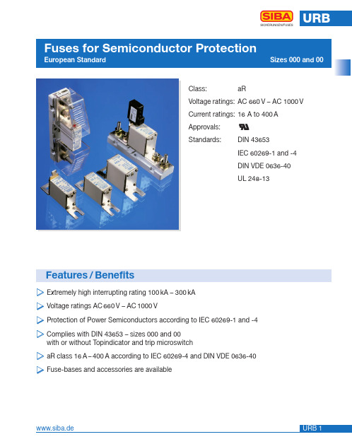
Class:aRVoltage ratings:AC 660V – AC 1000VCurrent ratings:16A to 400A Array Approvals:Standards:DIN 43653IEC 60269-1 and -4DIN VDE 0636-40UL 248-13Features/Benefits̈Extremely high interrupting rating 100kA – 300kÄVoltage ratings AC660V – AC1000V̈Protection of Power Semiconductors according to IEC 60269-1 and -4̈Complies with DIN 43653 – sizes 000 and 00with or without Topindicator and trip microswitcḧaR class 16A–400A according to IEC 60269-4 and DIN VDE 0636-40̈Fuse-bases and accessories are availableSelection Guide* Minimum operating voltage for top indicator 6.5VSize Rated Voltage Standard000AC 660 VDIN 43653Available in DC 700 V see URDC section.Size Rated Voltage Standard000AC 690/700 VDIN 43653A 2.17” (55mm)B 0.80” (20mm)C 0.33” (8.5mm)D 0.80” (20.4mm)E 3.07” (78mm)F 0.08” (2mm)I 1.54” (39mm)L (max)3.94” (100mm)Size Rated Voltage Standard000AC 660 VDIN 43653Size Rated Voltage Standard000AC 690/700 VDIN 43653A 2.17” (55mm)B 0.80” (20mm)C 0.33” (8,5mm)D 0.80” (20,4mm)E 3.07” (78mm)F 0.08” (2mm)G 2.10” (53mm)H 2.76” (70mm)I 1.54” (39mm)L (max)3.94” (100mm)Size Rated Voltage Standard00AC 660 VDIN 43653Size Rated Voltage Standard00AC 690/700 VDIN 43653A 2.17” (55mm)B 1.13” (28,8mm)C 0.40” (10,3mm)D 1.16” (29,5mm)E 3.07” (78mm)F 0.10” (2,5mm)I 1.85” (47mm)L (max) 4.13” (105mm)Size Rated Voltage Standard00AC 660 VDIN 43653A 2.17” (55mm)B 1.13” (28.8mm)C 0.40” (10.3mm)D 1.16” (29.5mm)E 3.07” (78mm)F 0.10” (2.5mm)G 2.48” (63mm)H 3.15” (80mm)I 1.54” (39mm)L (max)4.13” (105mm)Size Rated Voltage Standard00AC 690/700 VDIN 43653A 2.17” (55mm)B 1.13” (28.8mm)C 0.40” (10.3mm)D 1.16” (29.5mm)E 3.07” (78mm)F 0.10” (2.5mm)G 2.48” (63mm)H 3.15” (80mm)I 1.85” (47mm)L (max)4.13” (105mm)* 900 VacSize Rated Voltage Standard00AC 1000 VDIN 43653A 2.17” (55mm)B 1.13” (28,8mm)C 0.40” (10,3mm)D 1.16” (29,5mm)E 3.07” (78mm)F 0.10” (2,5mm)I 1.85” (47mm)L (max) 4.13” (105mm)* 900 VacSize Rated Voltage Standard00AC 1000 VDIN 43653A 2.17” (55mm)B 1.13” (28.8mm)C 0.40” (10.3mm)D 1.16” (29.5mm)E 3.07” (78mm)F 0.10” (2.5mm)G 2.48” (63mm)H 3.15” (80mm)I 1.85” (47mm)L (max)4.13” (105mm)Rated Voltage Operating Class 000AC 660 V aR100 kACut-Off characteristics Time-Current CharacteristicsV i r t u a l P r e -a r c i n g T i m eRMS Prospective Current Prospective Short Circuit Current t(s)I(A)I(kA)Arc voltage-Diagram Reduction factor for total I t-value Reduction factor for power lossURBSICHERUNGEN/FUSES000600V /200 kACut-Off characteristics Time-Current CharacteristicsV i r t u a l P r e -a r c i n g T i m eC u t -o f f C u r r e n t P e a kRMS Prospective Current Prospective Short Circuit Current t(s)Ic (kA)I(A)I(kA)Arc voltage-Diagram Reduction factor for total I t-value Reduction factor for power lossSICHERUNGEN/FUSESRated Voltage Operating Class00AC 660 V aR100 kACut-Off characteristics Time-Current CharacteristicsVirtualPre-arcingTimeCut-offCurrentPeakRMS Prospective CurrentProspective Short Circuit Currentt(s)Ic(kA)I(A)I(kA)Arc voltage-Diagram Reduction factor for total I t-value Reduction factor for power lossURBSICHERUNGEN/FUSES00600V /200 kACut-Off characteristics Time-Current CharacteristicsV i r t u a l P r e -a r c i n g T i m eC u t -o f f C u r r e n t P e a kProspective Short Circuit Current t(s)Ic (kA)I(kA)Arc voltage-Diagram Reduction factor for total I t-value Reduction factor for power lossRMS Prospective Current I(A)Cut-Off characteristics Time-Current CharacteristicsVi r t u a l P r e -a r c i n g T i m eC u t -o f f C u r r e n t P e a kProspective Short Circuit Current t(s)Ic (kA)I(kA)Arc voltage-Diagram Reduction factor for total I t-valueReduction factor for power lossSICHERUNGEN/FUSESRated Voltage Operating Class 00AC 1000 V aR100 kARMS Prospective Current I(A)URBSICHERUNGEN/FUSESElectrical characteristicsElectrical Characteristics A 4.96” (126mm)B 1.57” (40mm)C 0.50” (13mm)D 0.75” (19mm)E 3.15” (80mm)F 0.12” (3mm)G 1.73” (44mm)H 4.40” (112mm)I 0.26 ”(6,5 mm)J 0.60 ”(15,5 mm)K 0.63 ”(16 mm)L (max) 5.75 ”(146 mm)M M 8N 0.98 ”(25 mm)Rated Current: 400 ARated Power Acceptance: 34 W Nut Torque: 12 NmSize Rated VoltageStandardFuse-Base 400 A 000 and 00AC 1000 V DIN 436531000 V1000 VPart No. 21 189 08Rated Current: 400 ARated Power Acceptance: 34 W Nut Torque: 12 Nm with coversSize Rated Voltage StandardFuse-Base 400 A 000 and 00AC 1000 V DIN 43653URBSICHERUNGEN/FUSESA 4.96” (126mm)B 1.57” (40mm)C 0.50” (13mm)D 0.75” (19mm)E 3.15” (80mm)F 0.12” (3mm)G1 2.00” (51mm)G2 1.73” (44mm)H 4.40” (112mm)I 0.26 ”(6,5 mm)J 0.60 ”(15,5 mm)K 0.63 ”(16 mm)L (max) 5.75 ”(146 mm)M M 8N 0.98 ”(25 mm)Part No. 21 189 11Rated Current: 400 ARated Power Acceptance: 34 W Nut Torque: 12 Nm600 VSize Rated Voltage StandardFuse-Base 400 A 000 and 00AC 1000 V DIN 43653URBSICHERUNGEN/FUSESDimensionsPart No.28 002 01 (Black Hammer)Part No.28 002 02 (Red Hammer) Article usefor Weight Pack Number[kg]28 002 01NH00 DIN 800.021028 002 02NH000 DIN 800.0210Interrupting ratingAC 250 V AC 250 V DC 33 V DC 26 Vohmsch ind.ohmsch L/R 10 ms5 A 3 A3A3ATerminalsAMP 2,8 x 0,5 (IEC 760)Rated VoltageGL-Switch AC 250 V For Fuse-Links with Gripping LugsNotes SICHERUNGEN/FUSES。
rc0402fr-0710kl规格参数
rc0402fr-0710kl规格参数下载提示:该文档是本店铺精心编制而成的,希望大家下载后,能够帮助大家解决实际问题。
文档下载后可定制修改,请根据实际需要进行调整和使用,谢谢!本店铺为大家提供各种类型的实用资料,如教育随笔、日记赏析、句子摘抄、古诗大全、经典美文、话题作文、工作总结、词语解析、文案摘录、其他资料等等,想了解不同资料格式和写法,敬请关注!Download tips: This document is carefully compiled by this editor. I hope that after you download it, it can help you solve practical problems. The document can be customized and modified after downloading, please adjust and use it according to actual needs, thank you! In addition, this shop provides you with various types of practical materials, such as educational essays, diary appreciation, sentence excerpts, ancient poems, classic articles, topic composition, work summary, word parsing, copy excerpts, other materials and so on, want to know different data formats and writing methods, please pay attention!RC0402FR0710KL规格参数详解1. 概述RC0402FR0710KL是一种常用的电阻器,具有多种应用场景。
SEMIKRON ESD9L系列电路保护扇形电阻说明书

ESD9L, SESD9L Series Transient Voltage SuppressorsESD Protection Diodes with Ultra−Low CapacitanceThe ESD9L Series is designed to protect voltage sensitive components that require ultra−low capacitance from ESD and transient voltage events. Excellent clamping capability, low capacitance, low leakage, and fast response time, make these parts ideal for ESD protection on designs where board space is at a premium. Because of its low capacitance, it is suited for use in high frequency designs such as USB 2.0 high speed and antenna line applications.Specification Features:•Ultra Low Capacitance 0.5 pF •Low Clamping V oltage•Small Body Outline Dimensions:0.039″ x 0.024″(1.00 mm x 0.60 mm)•Low Body Height: 0.016″ (0.4 mm)•Stand−off V oltage: 3.3 V , 5 V •Low Leakage•Response Time is Typically < 1.0 ns •IEC61000−4−2 Level 4 ESD Protection•S and SZ Prefixes for Automotive and Other Applications Requiring Unique Site and Control Change Requirements; AEC−Q101Qualified and PPAP Capable•These Devices are Pb−Free and are RoHS CompliantMechanical Characteristics:CASE: V oid-free, transfer-molded, thermosetting plasticEpoxy Meets UL 94 V−0LEAD FINISH: 100% Matte Sn (Tin)MOUNTING POSITION: AnyQUALIFIED MAX REFLOW TEMPERATURE: 260°CDevice Meets MSL 1 RequirementsMAXIMUM RATINGSRatingSymbolValue Unit IEC 61000−4−2 (ESD)ContactAir±10±15kVTotal Power Dissipation on FR−5 Board (Note 1) @ T A = 25°C P D 150mW Storage Temperature Range T stg −55 to +150°CJunction Temperature Range T J −55 to +150°C Lead Solder Temperature − Maximum(10 Second Duration)TL 260°CStresses exceeding those listed in the Maximum Ratings table may damage the device. If any of these limits are exceeded, device functionality should not be assumed, damage may occur and reliability may be affected.1.FR−5 = 1.0 x 0.75 x 0.62 in.See Application Note AND8308/D for further description of survivability specs.Device PackageShipping †ORDERING INFORMATIONSOD−923CASE 514ABESD9LxxxST5G SOD−923(Pb−Free)8000/T ape & Reel MARKING DIAGRAMSee specific marking information in the device marking column of the Electrical Characteristics tables starting on page 2 of this data sheet.DEVICE MARKING INFORMATION†For information on tape and reel specifications,including part orientation and tape sizes, please refer to our T ape and Reel Packaging Specifications Brochure, BRD8011/D.X = Specific Device Code M = Date Code*Date Code orientation and/or position may vary depending upon manufacturing location.PIN 1.CATHODE2.ANODE12122SESD9LxxxST5G SOD−923(Pb−Free)8000/T ape & Reel SZESD9LxxxST5GSOD−923(Pb−Free)8000/T ape & ReelELECTRICAL CHARACTERISTICS(T A = 25°C unless otherwise noted)Symbol ParameterI PP Maximum Reverse Peak Pulse Current V C Clamping Voltage @ I PP V RWM Working Peak Reverse VoltageI R Maximum Reverse Leakage Current @ VRWM V BR Breakdown Voltage @ I T I T Test Current I F Forward Current V F Forward Voltage @ I F P pk Peak Power DissipationCMax. Capacitance @ V R = 0 and f = 1.0 MHz*See Application Note AND8308/D for detailed explanations of datasheet parameters.ELECTRICAL CHARACTERISTICS (T A = 25°C unless otherwise noted, V F = 1.0 V Max. @ I F = 10 mA for all types)Device*Device Marking V RWM (V)I R (m A)@ VRWM V BR (V) @ I T (Note 2)I T C (pF)V C (V)@ I PP = 1 AV CMax Max Min mA Typ Max Max Per IEC61000−4−2(Note 4)ESD9L3.3ST5G 6** 3.3 1.0 4.8 1.00.50.99.0Figures 1 and 2See Below ESD9L5.0ST5GD5.01.05.41.00.50.99.8Figures 1 and 2See Below*Includes S and SZ-prefix devices where applicable.**Rotated 180°.2.V BR is measured with a pulse test current I T at an ambient temperature of 25°C.3.Surge current waveform per Figure 5.4.For test procedure see Figures 3 and 4 and Application Note AND8307/D.Figure 1. ESD Clamping Voltage Screenshot Positive 8 kV Contact per IEC61000−4−2Figure 2. ESD Clamping Voltage Screenshot Negative 8 kV Contact per IEC61000−4−2IEC 61000−4−2 Spec.Level Test Volt-age (kV)First Peak Current (A)Current at 30 ns (A)Current at 60 ns (A)127.5422415843622.51264830168IEC61000−4−2 WaveformFigure 3. IEC61000−4−2 SpecOscilloscopeThe following is taken from Application NoteAND8308/D − Interpretation of Datasheet Parameters for ESD Devices.ESD Voltage ClampingFor sensitive circuit elements it is important to limit the voltage that an IC will be exposed to during an ESD event to as low a voltage as possible. The ESD clamping voltage is the voltage drop across the ESD protection diode during an ESD event per the IEC61000−4−2 waveform. Since the IEC61000−4−2 was written as a pass/fail spec for largersystems such as cell phones or laptop computers it is not clearly defined in the spec how to specify a clamping voltage at the device level. ON Semiconductor has developed a way to examine the entire voltage waveform across the ESD protection diode over the time domain of an ESD pulse in the form of an oscilloscope screenshot, which can be found on the datasheets for all ESD protection diodes. For more information on how ON Semiconductor creates these screenshots and how to interpret them please refer to AND8307/D.Figure 5. 8 X 20 ms Pulse Waveform1009080706050403020100t, TIME (m s)% O F P E A K P U L S E C U R R E N TPACKAGE DIMENSIONSSOD−923CASE 514AB ISSUE CNOTES:1.DIMENSIONING AND TOLERANCING PER ASME Y14.5M, 1994.2.CONTROLLING DIMENSION: MILLIMETERS.3.MAXIMUM LEAD THICKNESS INCLUDES LEAD FINISH. MINIMUM LEAD THICKNESS IS THE MINIMUM THICKNESS OF BASE MATERIAL.4.DIMENSIONS D AND E DO NOT INCLUDE MOLD FLASH, PROTRUSIONS, OR GATE BURRS.DIM MIN NOM MAX MILLIMETERS A 0.340.370.40b 0.150.200.25c 0.070.120.17D 0.750.800.85E 0.550.600.650.95 1.00 1.05L 0.19 REF H E 0.0130.0150.0160.0060.0080.0100.0030.0050.0070.0300.0310.0330.0220.0240.0260.0370.0390.0410.007 REFMIN NOM MAX INCHEScADIMENSIONS: MILLIMETERS*For additional information on our Pb−Free strategy and soldering details, please download the ON Semiconductor Soldering and Mounting Techniques Reference Manual, SOLDERRM/D.SOLDERING FOOTPRINT*See Application Note AND8455/D for more mounting details 2X0.252XOUTLINE2X0.08X YTOP VIEW2XBOTTOM VIEWL2XL20.050.100.150.0020.0040.006ON Semiconductor and are trademarks of Semiconductor Components Industries, LLC dba ON Semiconductor or its subsidiaries in the United States and/or other countries.ON Semiconductor owns the rights to a number of patents, trademarks, copyrights, trade secrets, and other intellectual property. A listing of ON Semiconductor’s product/patent PUBLICATION ORDERING INFORMATION。
九芯 8002B 音频功放芯片 数据手册

GUANGZHOU NINE CHIP ELECTRON TECHNOLOGY CO,. LTD.
8002B 音频功放芯片
8002B 功放芯片
数 据 手 册
Version Number 1.0
Reverse Date
2016.8.18
第一版本
1
Remark
广州市九芯电子科技有限公司
8002B 音频功放芯片
6
广州市九芯电子科技有限公司
GUANGZHOU NINE CHIP ELECTRON TECHNOLOGY CO,. LTD.
8002B 音频功放芯片
7
广州市九芯电子科技有限公司
GUANGZHOU NINE CHIP ELECTRON TECHNOLOGY CO,. LTD.
8002B 音频功放芯片
8.2 电源电压抑制比(PSRR)
8
广州市九芯电子科技有限公司
GUANGZHOU NINE CHIP ELECTRON TECHNOLOGY CO,. LTD.
PSRR vs FrequencyVDD=5V,RL=8Ω,输入接10Ω电阻
8002B 音频功放芯片
PSRR vs Frequency VDD=5V,RL=8Ω,输入悬空
GUANGZHOU NINE CHIP ELECTRON TECHNOLOGY CO,. LTD.
8002B 音频功放芯片
目录
1 功能说明 .........................................................................................................................................3 2 主要特性 .........................................................................................................................................3 3 应用领域 .........................................................................................................................................3 4 典型应用电路 .................................................................................................................................3 5 极限参数 .........................................................................................................................................4 6 电气特性 .........................................................................................................................................4 7 芯片管脚描述 .................................................................................................................................5
wepr22010c电源模块说明书

wepr22010c电源模块说明书
wepr22010c电源模块是一款高效、可靠、稳定的直流电源模块。
该模块采用进口元器件,结构紧凑,体积小,可广泛应用于电子设备、通讯设备、工业自动化控制等领域。
主要参数:
1. 输入电压:AC 85-265V
2. 输出电压:DC 2-24V (可调节)
3. 输出电流:0-10A (可调节)
4. 输出功率:200W
5. 效率:≥ 90%
6. 工作温度:-40℃~+85℃
安全保护:
1. 过流保护
2. 过压保护
3. 短路保护
4. 过热保护
使用注意事项:
1. 输入电压必须在规定的范围内。
2. 请勿超过模块的电压或电流输出范围。
3. 请勿在潮湿、高温、高压等恶劣环境下使用。
4. 请勿自行打开模块进行维修,如需维修请联系厂家或专业人士。
希望以上信息能够帮到您,如还有其他问题请随时咨询。
74LVC2GU04双非缓冲非门数据手册说明书
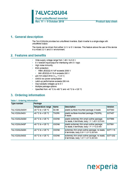
74LVC2GU04Dual unbuffered inverterRev. 11 — 9 October 2018Product data sheet1. General descriptionThe 74LVC2GU04 provides two unbuffered inverters. Each inverter is a single stage withunbuffered output.The inputs can be driven from either 3.3 V or 5 V devices. This feature allows the use of this devicein a mixed 3.3 V and 5 V environment.2. Features and benefits•Wide supply voltage range from 1.65 V to 5.5 V• 5 V tolerant input/output for interfacing with 5 V logic•High noise immunity•ESD protection:•HBM JESD22-A114F exceeds 2000 V•MM JESD22-A115-A exceeds 200 V•±24 mA output drive (V CC = 3.0 V)•CMOS low power consumption•Latch-up performance exceeds 250 mA•Input accepts voltages up to 5 V•Multiple package options•Specified from -40 °C to +85 °C and -40 °C to +125 °C3. Ordering information4. Marking[1]The pin 1 indicator is located on the lower left corner of the device, below the marking code.5. Functional diagram6. Pinning information6.1. Pinning74LVC2GU041A 1Y GND 2A2Y001aab6801236V CC 54Fig. 4.Pin configuration SOT363 (SC-88)and SOT457 (TSOP6)74LVC2GU04GND001aab6811A2A V CC1Y2YT ransparent top view231546Fig. 5.Pin configuration SOT886 (XSON6)74LVC2GU04GND 001aag4211A2AV CC 1Y 2YT ransparent top view231546Fig. 6.Pin configuration SOT891, SOT1115and SOT1202 (XSON6)6.2. Pin description7. Functional descriptionTable 4. Function tableH = HIGH voltage level; L = LOW voltage level.8. Limiting valuesTable 5. Limiting valuesIn accordance with the Absolute Maximum Rating System (IEC 60134). Voltages are referenced to GND (ground = 0 V).[1]The minimum input and output voltage ratings may be exceeded if the input and output current ratings are observed.[2]When V CC = 0 V (Power-down mode), the output voltage can be 5.5 V in normal operation.[3]For SC-88 and TSOP6 packages: above 87.5 °C the value of P tot derates linearly with 4.0 mW/K.For XSON6 packages: above 118 °C the value of P tot derates linearly with 7.8 mW/K.9. Recommended operating conditionsTable 6. Recommended operating conditionsVoltages are referenced to GND (ground = 0 V).10. Static characteristicsTable 7. Static characteristicsAt recommended operating conditions; voltages are referenced to GND (ground = 0 V).[1]All typical values are measured at V CC = 3.3 V and at T amb = 25 °C.11. Dynamic characteristicsTable 8. Dynamic characteristicsVoltages are referenced to GND (ground = 0 V). For test circuit see Fig. 8.[1]Typical values are measured at T amb = 25 °C and V CC = 1.8 V, 2.5 V, 2.7 V, 3.3 V and 5.0 V respectively.[2]t pd is the same as t PLH and t PHL.[3]C PD is used to determine the dynamic power dissipation (P D in μW).P D = C PD × V CC2 × f i × N + ∑(C L × V CC2 × f o) where:f i = input frequency in MHz;f o = output frequency in MHz;C L = output load capacitance in pF;V CC = supply voltage in V;N = number of inputs switching;∑(C L × V CC2 × f o) = sum of outputs.11.1. Waveforms and test circuit12. Application informationSome applications are:•Linear amplifier (see Fig. 11)•In crystal oscillator design (see Fig. 12)Remark: All values given are typical unless otherwise specified.13. Package outlinePlastic surface-mounted package; 6 leads SOT363Fig. 13.Package outline SOT363 (SC-88)Plastic surface-mounted package (TSOP6); 6 leads SOT457Fig. 14.Package outline SOT457 (TSOP6)Fig. 15.Package outline SOT886 (XSON6)Fig. 16.Package outline SOT891 (XSON6)XSON6: extremely thin small outline package; no leads;Fig. 17.Package outline SOT1115 (XSON6)XSON6: extremely thin small outline package; no leads;Fig. 18.Package outline SOT1202 (XSON6)14. Abbreviations15. Revision history16. Legal informationData sheet status[1]Please consult the most recently issued document before initiating orcompleting a design.[2]The term 'short data sheet' is explained in section "Definitions".[3]The product status of device(s) described in this document may havechanged since this document was published and may differ in case ofmultiple devices. The latest product status information is available onthe internet at https://.DefinitionsDraft — The document is a draft version only. The content is still under internal review and subject to formal approval, which may result in modifications or additions. Nexperia does not give any representations or warranties as to the accuracy or completeness of information included herein and shall have no liability for the consequences of use of such information. Short data sheet — A short data sheet is an extract from a full data sheet with the same product type number(s) and title. A short data sheet is intended for quick reference only and should not be relied upon to contain detailed and full information. For detailed and full information see the relevant full data sheet, which is available on request via the local Nexperia sales office. In case of any inconsistency or conflict with the short data sheet, the full data sheet shall prevail.Product specification — The information and data provided in a Product data sheet shall define the specification of the product as agreed between Nexperia and its customer, unless Nexperia and customer have explicitly agreed otherwise in writing. In no event however, shall an agreement be valid in which the Nexperia product is deemed to offer functions and qualities beyond those described in the Product data sheet.DisclaimersLimited warranty and liability — Information in this document is believedto be accurate and reliable. However, Nexperia does not give any representations or warranties, expressed or implied, as to the accuracyor completeness of such information and shall have no liability for the consequences of use of such information. Nexperia takes no responsibility for the content in this document if provided by an information source outside of Nexperia.In no event shall Nexperia be liable for any indirect, incidental, punitive, special or consequential damages (including - without limitation - lost profits, lost savings, business interruption, costs related to the removalor replacement of any products or rework charges) whether or not such damages are based on tort (including negligence), warranty, breach of contract or any other legal theory.Notwithstanding any damages that customer might incur for any reason whatsoever, Nexperia’s aggregate and cumulative liability towards customer for the products described herein shall be limited in accordance with the Terms and conditions of commercial sale of Nexperia.Right to make changes — Nexperia reserves the right to make changesto information published in this document, including without limitation specifications and product descriptions, at any time and without notice. This document supersedes and replaces all information supplied prior to the publication hereof.Suitability for use — Nexperia products are not designed, authorized or warranted to be suitable for use in life support, life-critical or safety-critical systems or equipment, nor in applications where failure or malfunctionof an Nexperia product can reasonably be expected to result in personal injury, death or severe property or environmental damage. Nexperia and its suppliers accept no liability for inclusion and/or use of Nexperia products in such equipment or applications and therefore such inclusion and/or use is at the customer’s own risk.Quick reference data — The Quick reference data is an extract of the product data given in the Limiting values and Characteristics sections of this document, and as such is not complete, exhaustive or legally binding. Applications — Applications that are described herein for any of these products are for illustrative purposes only. Nexperia makes no representation or warranty that such applications will be suitable for the specified use without further testing or modification.Customers are responsible for the design and operation of their applications and products using Nexperia products, and Nexperia accepts no liability for any assistance with applications or customer product design. It is customer’s sole responsibility to determine whether the Nexperia product is suitableand fit for the customer’s applications and products planned, as well asfor the planned application and use of customer’s third party customer(s). Customers should provide appropriate design and operating safeguards to minimize the risks associated with their applications and products. Nexperia does not accept any liability related to any default, damage, costs or problem which is based on any weakness or default in the customer’s applications or products, or the application or use by customer’s third party customer(s). Customer is responsible for doing all necessary testing for the customer’s applications and products using Nexperia products in order to avoid a default of the applications and the products or of the application or use by customer’s third party customer(s). Nexperia does not accept any liability in this respect.Limiting values — Stress above one or more limiting values (as defined in the Absolute Maximum Ratings System of IEC 60134) will cause permanent damage to the device. Limiting values are stress ratings only and (proper) operation of the device at these or any other conditions above thosegiven in the Recommended operating conditions section (if present) or the Characteristics sections of this document is not warranted. Constant or repeated exposure to limiting values will permanently and irreversibly affect the quality and reliability of the device.Terms and conditions of commercial sale — Nexperia products aresold subject to the general terms and conditions of commercial sale, as published at /profile/terms, unless otherwise agreed in a valid written individual agreement. In case an individual agreement is concluded only the terms and conditions of the respective agreement shall apply. Nexperia hereby expressly objects to applying the customer’s general terms and conditions with regard to the purchase of Nexperia products by customer.No offer to sell or license — Nothing in this document may be interpreted or construed as an offer to sell products that is open for acceptance or the grant, conveyance or implication of any license under any copyrights, patents or other industrial or intellectual property rights.Export control — This document as well as the item(s) described herein may be subject to export control regulations. Export might require a prior authorization from competent authorities.Non-automotive qualified products — Unless this data sheet expressly states that this specific Nexperia product is automotive qualified, the product is not suitable for automotive use. It is neither qualified nor tested in accordance with automotive testing or application requirements. Nexperia accepts no liability for inclusion and/or use of non-automotive qualified products in automotive equipment or applications.In the event that customer uses the product for design-in and use in automotive applications to automotive specifications and standards, customer (a) shall use the product without Nexperia’s warranty of the product for such automotive applications, use and specifications, and (b) whenever customer uses the product for automotive applications beyond Nexperia’s specifications such use shall be solely at customer’s own risk, and (c) customer fully indemnifies Nexperia for any liability, damages or failed product claims resulting from customer design and use of the product for automotive applications beyond Nexperia’s standard warranty and Nexperia’s product specifications.Translations — A non-English (translated) version of a document is for reference only. The English version shall prevail in case of any discrepancy between the translated and English versions.TrademarksNotice: All referenced brands, product names, service names and trademarks are the property of their respective owners.Contents1. General description (1)2. Features and benefits (1)3. Ordering information (1)4. Marking (2)5. Functional diagram (2)6. Pinning information (2)6.1. Pinning (2)6.2. Pin description (3)7. Functional description (3)8. Limiting values (3)9. Recommended operating conditions (4)10. Static characteristics (4)11. Dynamic characteristics (5)11.1. Waveforms and test circuit (5)12. Application information (7)13. Package outline (8)14. Abbreviations (14)15. Revision history (14)16. Legal information (15)© Nexperia B.V. 2018. All rights reservedFor more information, please visit: Forsalesofficeaddresses,pleasesendanemailto:*************************** Date of release: 9 October 2018Mouser ElectronicsAuthorized DistributorClick to View Pricing, Inventory, Delivery & Lifecycle Information:N experia:74LVC2GU04GN,13274LVC2GU04GS,13274LVC2GU04GM,11574LVC2GU04GM,13274LVC2GU04GV,125 74LVC2GU04GW,12574LVC2GU04GF,132。
PCB Model 482C05 Four-channel, ICP Sensor Signal C
Model 482C05Four-channel, ICP® Sensor Signal Conditioner Installation and Operating ManualFor assistance with the operation of this product,contact PCB Piezotronics, Inc.Toll-free: 800-828-884024-hour SensorLine: 716-684-0001Fax: 716-684-0987E-mail:************Web: Repair and MaintenancePCB guarantees Total Customer Satisfaction through its “Lifetime Warranty Plus” on all Platinum Stock Products sold by PCB and through its limited warranties on all other PCB Stock, Standard and Special products. Due to the sophisticated nature of our sensors and associated instrumentation, field servicing and repair is not recommended and, if attempted, will void the factory warranty.Beyond routine calibration and battery replacements where applicable, our products require no user maintenance. Clean electrical connectors, housings, and mounting surfaces with solutions and techniques that will not harm the material of construction. Observe caution when using liquids near devices that are not hermetically sealed. Such devices should only be wiped with a dampened cloth—never saturated or submerged.In the event that equipment becomes damaged or ceases to operate, our Application Engineers are here to support your troubleshooting efforts 24 hours a day, 7 days a week. Call or email with model and serial number as well as a brief description of the problem. CalibrationRoutine calibration of sensors and associated instrumentation is necessary to maintain measurement accuracy. We recommend calibrating on an annual basis, after exposure to any extreme environmental influence, or prior to any critical test.PCB Piezotronics is an ISO-9001 certified company whose calibration services are accredited by A2LA to ISO/IEC 17025, with full traceability to SI through N.I.S.T. In addition to our standard calibration services, we also offer specialized tests, including: sensitivity at elevated or cryogenic temperatures, phase response, extended high or low frequency response, extended range, leak testing, hydrostatic pressure testing, and others. For more information, contact your local PCB Piezotronics distributor, sales representative, or factory customer service representative. Returning EquipmentIf factory repair is required, our representatives will provide you with a Return Material Authorization (RMA) number, which we use to reference any information you have already provided and expedite the repair process. This number should be clearly marked on the outside of all returned package(s) and on any packing list(s) accompanying the shipment.Contact InformationPCB Piezotronics, Inc.3425 Walden Ave.Depew, NY14043 USAToll-free: (800) 828-884024-hour SensorLine: (716) 684-0001General inquiries: ************Repair inquiries: ***********For a complete list of distributors, global offices and sales representatives, visit our website, .Safety ConsiderationsThis product is intended for use by qualified personnel who recognize shock hazards and are familiar with the precautions required to avoid injury. While our equipment is designed with user safety in mind, the protection provided by the equipment may be impaired if equipment is used in a manner not specified by this manual.Discontinue use and contact our 24-Hour Sensorline if:∙Assistance is needed to safely operate equipment∙Damage is visible or suspected∙Equipment fails or malfunctionsFor complete equipment ratings, refer to the enclosed specification sheet for your product.Definition of Terms and SymbolsThe following symbols may be used in this manual:DANGERIndicates an immediate hazardoussituation, which, if not avoided, mayresult in death or serious injury.CAUTIONRefers to hazards that could damage the instrument.NOTEIndicates tips, recommendations and important information. The notes simplify processes and containadditional information on particular operating steps.The following symbols may be found on the equipment described in this manual:This symbol on the unit indicates that high voltage may be present. Use standard safety precautions to avoid personal contact with this voltage.This symbol on the unit indicates that the user should refer to the operating instructions located in the manual.This symbol indicates safety, earth ground.PCB工业监视和测量设备 - 中国RoHS2公布表PCB Industrial Monitoring and Measuring Equipment - China RoHS 2 Disclosure Table部件名称有害物质铅 (Pb)汞(Hg)镉(Cd) 六价铬 (Cr(VI)) 多溴联苯 (PBB) 多溴二苯醚 (PBDE)住房O O O O O O PCB板X O O O O O 电气连接器O O O O O O 压电晶体X O O O O O 环氧O O O O O O 铁氟龙O O O O O O 电子O O O O O O 厚膜基板O O X O O O 电线O O O O O O 电缆X O O O O O 塑料O O O O O O 焊接X O O O O O 铜合金/黄铜X O O O O O 本表格依据 SJ/T 11364 的规定编制。
NXP BAP70-02 平面PIN晶体管数据手册说明书
BAP70-02Silicon PIN diodeRev. 8 — 11 December 2018Product data sheet1Product profile1.1General descriptionPlanar PIN diode in a SOD523 ultra small SMD plastic package.1.2Features and benefits•High voltage; current controlled RF resistor for attenuators •Low diode capacitance •Very low series inductance •AEC-Q101 qualified1.3Applications•RF attenuators •(SAT) TV •Car radio2Pinning information3Ordering informationSilicon PIN diode 4Marking[1]The marking bar indicates the cathode (see simplified outline graphic in Table 1)5Limiting valuesTable 4. Limiting valuesIn accordance with the Absolute Maximum Rating System (IEC 60134).6Thermal characteristics7CharacteristicsTable 6. CharacteristicsT= 25 °C unless otherwise specified.Silicon PIN diode8Graphical dataSilicon PIN diode 9Package outline10AbbreviationsSilicon PIN diode 11Revision historySilicon PIN diode 12Legal information12.1 Data sheet status[1]Please consult the most recently issued document before initiating or completing a design.[2]The term 'short data sheet' is explained in section "Definitions".[3]The product status of device(s) described in this document may have changed since this document was published and may differ in case of multipledevices. The latest product status information is available on the Internet at URL .12.2 DefinitionsDraft — The document is a draft version only. The content is still under internal review and subject to formal approval, which may result in modifications or additions. NXP Semiconductors does not give any representations or warranties as to the accuracy or completeness of information included herein and shall have no liability for the consequences of use of such information.Short data sheet — A short data sheet is an extract from a full data sheet with the same product type number(s) and title. A short data sheet is intended for quick reference only and should not be relied upon to contain detailed and full information. For detailed and full information see the relevant full data sheet, which is available on request via the local NXP Semiconductors sales office. In case of any inconsistency or conflict with the short data sheet, the full data sheet shall prevail.Product specification — The information and data provided in a Product data sheet shall define the specification of the product as agreed between NXP Semiconductors and its customer, unless NXP Semiconductors and customer have explicitly agreed otherwise in writing. In no event however, shall an agreement be valid in which the NXP Semiconductors productis deemed to offer functions and qualities beyond those described in the Product data sheet.12.3 DisclaimersLimited warranty and liability — Information in this document is believed to be accurate and reliable. However, NXP Semiconductors does notgive any representations or warranties, expressed or implied, as to the accuracy or completeness of such information and shall have no liabilityfor the consequences of use of such information. NXP Semiconductors takes no responsibility for the content in this document if provided by an information source outside of NXP Semiconductors. In no event shall NXP Semiconductors be liable for any indirect, incidental, punitive, special or consequential damages (including - without limitation - lost profits, lost savings, business interruption, costs related to the removal or replacement of any products or rework charges) whether or not such damages are based on tort (including negligence), warranty, breach of contract or any other legal theory. Notwithstanding any damages that customer might incur for any reason whatsoever, NXP Semiconductors’ aggregate and cumulative liability towards customer for the products described herein shall be limited in accordance with the Terms and conditions of commercial sale of NXP Semiconductors.Right to make changes — NXP Semiconductors reserves the right to make changes to information published in this document, including without limitation specifications and product descriptions, at any time and without notice. This document supersedes and replaces all information supplied prior to the publication hereof.Applications — Applications that are described herein for any of these products are for illustrative purposes only. NXP Semiconductors makesno representation or warranty that such applications will be suitablefor the specified use without further testing or modification. Customersare responsible for the design and operation of their applications and products using NXP Semiconductors products, and NXP Semiconductors accepts no liability for any assistance with applications or customer product design. It is customer’s sole responsibility to determine whether the NXP Semiconductors product is suitable and fit for the customer’s applications and products planned, as well as for the planned application and use of customer’s third party customer(s). Customers should provide appropriate design and operating safeguards to minimize the risks associated withtheir applications and products. NXP Semiconductors does not accept any liability related to any default, damage, costs or problem which is basedon any weakness or default in the customer’s applications or products, or the application or use by customer’s third party customer(s). Customer is responsible for doing all necessary testing for the customer’s applications and products using NXP Semiconductors products in order to avoid a default of the applications and the products or of the application or use by customer’s third party customer(s). NXP does not accept any liability in this respect.Limiting values — Stress above one or more limiting values (as defined in the Absolute Maximum Ratings System of IEC 60134) will cause permanent damage to the device. Limiting values are stress ratings only and (proper) operation of the device at these or any other conditions above thosegiven in the Recommended operating conditions section (if present) or the Characteristics sections of this document is not warranted. Constant or repeated exposure to limiting values will permanently and irreversibly affect the quality and reliability of the device.Terms and conditions of commercial sale — NXP Semiconductors products are sold subject to the general terms and conditions of commercial sale, as published at /profile/terms, unless otherwise agreed in a valid written individual agreement. In case an individual agreement is concluded only the terms and conditions of the respective agreement shall apply. NXP Semiconductors hereby expressly objects to applying the customer’s general terms and conditions with regard to the purchase of NXP Semiconductors products by customer.No offer to sell or license — Nothing in this document may be interpreted or construed as an offer to sell products that is open for acceptance orthe grant, conveyance or implication of any license under any copyrights, patents or other industrial or intellectual property rights.Suitability for use in automotive applications — This NXP Semiconductors product has been qualified for use in automotive applications. Unless otherwise agreed in writing, the product is not designed, authorized or warranted to be suitable for use in life support, life-critical or safety-critical systems or equipment, nor in applications where failure or malfunction of an NXP Semiconductors product can reasonably be expectedSilicon PIN diodeto result in personal injury, death or severe property or environmental damage. NXP Semiconductors and its suppliers accept no liability for inclusion and/or use of NXP Semiconductors products in such equipment or applications and therefore such inclusion and/or use is at the customer's own risk.Export control — This document as well as the item(s) described herein may be subject to export control regulations. Export might require a prior authorization from competent authorities.Translations — A non-English (translated) version of a document is for reference only. The English version shall prevail in case of any discrepancy between the translated and English versions.12.4 TrademarksNotice: All referenced brands, product names, service names and trademarks are the property of their respective owners.Silicon PIN diodePlease be aware that important notices concerning this document and the product(s)described herein, have been included in section 'Legal information'.Contents1Product profile ....................................................11.1General description ............................................11.2Features and benefits ........................................11.3Applications ........................................................12Pinning information ............................................13Ordering information ..........................................14Marking .................................................................25Limiting values ....................................................26Thermal characteristics ......................................27Characteristics ....................................................28Graphical data .....................................................39Package outline ...................................................410Abbreviations ......................................................411Revision history .. (512)Legal information (6)。
brazing solder cp102 标准
CP102 是一种常用的铜磷焊料(brazing solder),主要用于金属材料的焊接和钎焊。
其成分和性能符合AWS(美国焊接协会)的标准。
CP102 的主要成分如下:- 铜(Cu):约63%- 磷(P):约0.1%- 锌(Zn):约36.5%- 铝(Al):约0.1%- 镍(Ni):约0.5%- 锰(Mn):约0.1%- 硅(Si):约0.1%- 铁(Fe):约0.1%CP102 焊料的性能特点如下:1. 良好的润湿性:在适当的焊接条件下,CP102 能迅速润湿焊接表面,形成焊缝。
2. 良好的焊接性能:CP102 焊料在焊接过程中产生较少的气体、夹渣等缺陷,焊缝成型美观。
3. 强度高:CP102 焊料焊接后的焊缝具有较高的强度,能满足大部分焊接应用的要求。
4. 耐腐蚀性好:CP102 焊料焊接的焊缝具有良好的耐腐蚀性能,适用于化工、航空航天等领域的焊接应用。
5. 可靠性高:CP102 焊料在焊接过程中稳定,不易出现焊缝开裂、脱落等现象。
根据AWS 标准,CP102 焊料适用于以下应用场景:1. 焊接铜及铜合金材料,如管道、阀门、散热器等。
2. 钎焊不锈钢、镍基合金等高温合金材料。
3. 焊接电子元器件、汽车零部件等需要高强度、低合金的场合。
4. 焊接具有较高要求的航空航天、化工、核工业等领域的设备。
在使用CP102 焊料时,需注意以下要点:1. 焊接前,需对焊接表面进行清洁,去除油污、氧化物等。
2. 控制焊接温度,避免过高的温度导致焊缝质量下降。
3. 选择适当的焊接方法,如TIG 焊接、MIG 焊接等。
4. 合理设置焊接参数,如焊接电流、电压、焊接速度等,以保证焊缝质量。
5. 焊接后,及时进行冷却,以降低焊缝产生裂纹的风险。
元器件4082用法
元器件4082用法
元器件4082是一个通用的型号,通常用于指代不同类型的电子元器件,比如电容、电阻、集成电路等。
因此,要了解元器件4082的用法,需要具体指明是哪种类型的元器件。
如果你指的是电容器或者电阻器件,那么元器件4082可能是一个特定型号的电容或电阻。
在这种情况下,你需要查找该型号的规格书或者数据手册,以了解它的参数、用法和特性。
通常,这些手册会提供关于元器件的引脚定义、工作电压、额定电流、温度范围等重要信息。
如果你指的是集成电路或其他类型的元器件,同样需要查找相关的规格书或数据手册。
这些手册会详细介绍元器件的功能、引脚定义、工作条件、电气特性等。
另外,如果你是在特定的电路设计或项目中使用元器件4082,建议你咨询电子工程师或者具有相关经验的专业人士,以获取关于元器件用法的具体建议和指导。
总之,了解元器件4082的用法需要具体参考该元器件的规格书
或数据手册,并在实际应用中谨慎使用,以确保符合相关的电气安全标准和设计要求。
CC0402BRNPO9BN2R0中文资料
物料编号:CC0402BRNPO9BN2R0细参数_易容网
MLCC即是多层陶瓷电容片式,是电子信息产品不可或缺的基本组件之一。
我国MLCC的生产起步在80年代初,行业早期主要是在外资企业的带动下发展起来的,近年来国内企业在技术上实现突破,行业国产化成效显著,并推动了MLCC产量迅速增长。
目前,MLCC的应用领域已从手机、电脑、电视机等消费电子领域,逐步拓展到新能源发电、新能源汽车、节能灯具、轨道交通、直流输变电、三网融合、高清电视、机顶盒、手机电视等多个行业。
对于这个悄悄活跃在人们生活中的元件你又知道多少呢.
本次易容网为大家推荐比较常用的MLCC国巨 | Yageo品牌的料号CC0402BRNPO9BN2R0的相关参数
易容网是深圳市易容信息技术有限公司独自研发的全球最大的MLCC搜索采购服务网站,2014年创立于深圳市南山区,全国首家电子元器件行业电容元件的搜索引擎及o2o商务服务平台。
易容网()现已建成全球最大的MLCC电容搜索引擎数据库,包含全球25家电容生产厂商超过28万组MLCC产品数据,用户可根据行业应用、物料编号、规格参数等信息快速的找到所有相关的MLCC电容数据。
易容网在搜索服务的前提下还提供村田、TDK、国巨、太阳诱电、风华高科等常见品牌产品的o2o商务服务,让企业客户实现询价、报价、在线订单、出库、实时物流、签收、账期服务等在线一站式商务服务体验。
FOSAN富信电子 三极管 2SC4115-产品规格书
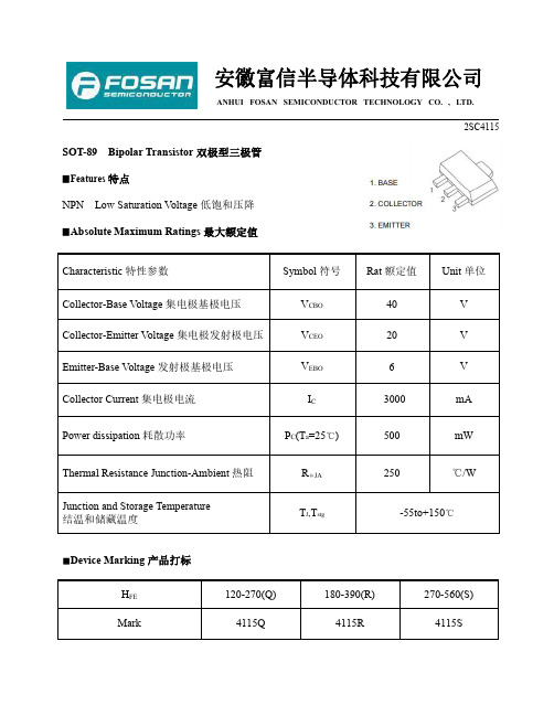
安徽富信半导体科技有限公司ANHUI FOSAN SEMICONDUCTOR TECHNOLOGY CO.,LTD.2SC4115SOT-89Bipolar Transistor双极型三极管▉Features特点NPN Low Saturation Voltage低饱和压降▉Absolute Maximum Ratings最大额定值Characteristic特性参数Symbol符号Rat额定值Unit单位Collector-Base Voltage集电极基极电压V CBO40V Collector-Emitter Voltage集电极发射极电压V CEO20V Emitter-Base Voltage发射极基极电压V EBO6V Collector Current集电极电流I C3000mA Power dissipation耗散功率P C(T a=25℃)500mW Thermal Resistance Junction-Ambient热阻RΘJA250℃/WJunction and Storage TemperatureT J,T stg-55to+150℃结温和储藏温度■Device Marking产品打标H FE120-270(Q)180-390(R)270-560(S)Mark4115Q4115R4115SANHUI FOSAN SEMICONDUCTOR TECHNOLOGY CO.,LTD.2SC4115■ElectricalCharacteristics 电特性(T A =25℃unless otherwise noted 如无特殊说明,温度为25℃)Characteristic 特性参数Symbol 符号Min 最小值Type 典型值Max 最大值Unit 单位Collector-Base Breakdown V oltage集电极基极击穿电压(I C =50µA ,I E =0)BV CBO 40——V Collector-Emitter Breakdown Voltage 集电极发射极击穿电压(I C =1mA ,I B =0)BV CEO 20——V Emitter-Base Breakdown V oltage发射极基极击穿电压(I E =50µA ,I C =0)BV EBO 6——V Collector-Base Leakage Current集电极基极漏电流(V CB =30V ,I E =0)I CBO ——0.1µA Emitter-Base Leakage Current发射极基极漏电流(V EB =5V ,I C =0)I EBO ——0.1µADC Current Gain直流电流增益(V CE =2V ,I C =100mA)H FE120—560Collector-Emitter Saturation Voltage集电极发射极饱和压降(I C =2A ,I B =100mA)V CE(sat)——0.5VBase-Emitter Saturation V oltage基极发射极饱和压降(I C =2A ,I B =100mA)V BE(sat)—— 1.2V Transition Frequency特征频率(V CE =2V ,I C =500mA)f T—290—MH ZOutput Capacitance输出电容(V CB =10V ,I E =0,f=1MH Z )C ob—60—pFANHUI FOSAN SEMICONDUCTOR TECHNOLOGY CO.,LTD.2SC4115■Typical Characteristic Curve典型特性曲线ANHUI FOSAN SEMICONDUCTOR TECHNOLOGY CO.,LTD.2SC4115■Dimension外形封装尺寸。
0.2ω 合金电阻 -回复
0.2ω合金电阻-回复什么是0.2ω合金电阻以及它的作用?0.2ω合金电阻(也称为0.2欧姆合金电阻)是一种电子元件,用于电子电路中的电阻器。
它的阻值为0.2欧姆,可以提供特定的电阻值来限制电路中的电流流动。
合金电阻器是一种基于合金材料制造的电阻,它具有较为稳定的温度系数和精确的阻值。
一般而言,合金电阻器通过将金属合金导线缠绕成螺旋状或扁平形式来实现其电阻值。
它通常被用于需要稳定电阻值和温度系数的电路,例如功率放大器、模拟电路和数字电路。
那么为什么选择0.2ω合金电阻?通常情况下,电路的设计师会根据系统要求和预期的电流范围来选择电阻值。
0.2欧姆合金电阻通常用于需要低电阻值并控制电流的电路中。
它的阻值相对较小,适合一些特定的应用场景,例如功率放大器的输入端、电机驱动电路等。
在电路中,0.2欧姆合金电阻的作用非常重要。
首先,它可以实现电流的限制和控制。
当电流流经电路时,0.2欧姆合金电阻会产生电压降,在电阻两端形成一个电势差,进而限制电流的流动。
这对于一些需要控制电流幅度的电路来说非常关键,例如功率放大器中的负载电流控制。
其次,0.2欧姆合金电阻还起到稳定电路性能的作用。
由于合金电阻器具有较为稳定的温度系数,它可以在不同温度环境下保持相对稳定的电阻值。
这样可以使电路在不同工作条件下仍能有效工作,而不至于因为温度变化而出现性能失效。
此外,0.2欧姆合金电阻还可以用于提供电压分压功能。
在一些电路中,我们需要将电压进行分压来满足特定需求,0.2欧姆合金电阻可以作为分压电阻来实现这个功能。
通过将合适的合金电阻器连接在电路中,可以将整体电压进行分割,使得不同的电路模块可以工作在不同的电压范围中。
一般而言,选择0.2η合金电阻还需要考虑一些其他因素,例如功率容量、耐压能力等。
根据具体应用场景和需求,设计师还需要综合考虑这些因素来选择合适的0.2欧姆合金电阻。
总结起来,0.2欧姆合金电阻是一种常见的电子元件,具有较为稳定的温度系数和精确的阻值。
- 1、下载文档前请自行甄别文档内容的完整性,平台不提供额外的编辑、内容补充、找答案等附加服务。
- 2、"仅部分预览"的文档,不可在线预览部分如存在完整性等问题,可反馈申请退款(可完整预览的文档不适用该条件!)。
- 3、如文档侵犯您的权益,请联系客服反馈,我们会尽快为您处理(人工客服工作时间:9:00-18:30)。
物料编号:CC0402BRNPO9BNR82细参数_易容网
MLCC即是多层陶瓷电容片式,是电子信息产品不可或缺的基本组件之一。
我国MLCC的生产起步在80年代初,行业早期主要是在外资企业的带动下发展起来的,近年来国内企业在技术上实现突破,行业国产化成效显著,并推动了MLCC产量迅速增长。
目前,MLCC的应用领域已从手机、电脑、电视机等消费电子领域,逐步拓展到新能源发电、新能源汽车、节能灯具、轨道交通、直流输变电、三网融合、高清电视、机顶盒、手机电视等多个行业。
对于这个悄悄活跃在人们生活中的元件你又知道多少呢.
本次易容网为大家推荐比较常用的MLCC国巨 | Yageo品牌的料号CC0402BRNPO9BNR8
的相关参数
易容网是深圳市易容信息技术有限公司独自研发的全球最大的MLCC搜索采购服务网站,2014年创立于深圳市南山区,全国首家电子元器件行业电容元件的搜索引擎及o2o商务服务平台。
易容网()现已建成全球最大的MLCC电容搜索引擎数据库,包含全球25家电容生产厂商超过28万组MLCC产品数据,用户可根据行业应用、物料编号、规格参数等信息快速的找到所有相关的MLCC电容数据。
易容网在搜索服务的前提下还提供村田、TDK、国巨、太阳诱电、风华高科等常见品牌产品的o2o商务服务,让企业客户实现询价、报价、在线订单、出库、实时物流、签收、账期服务等在线一站式商务服务体验。
