MAAMSS0005中文资料
美国AEMC公司高端和可移动数字弱电阻抗度计6550和6555产品说明书

Technical Assistance (800) 343-1391 110kV and 15kV DigitalMegohmmetersModels 6550 & 6555► Insulation measurementup to 30T Ω► Test voltages up to 15,000V► Step, ramp & fixed voltagetesting► Multiple test modes: voltageramp and step with “Burn-In”, “Early-Break” and “I-Limit” modes► 3 filter choices to optimize measurement stability► Selectable voltage from40V to 10,000 / 15,000V ► Storage of up to 80,000 measurements► Optically-isolated USBcommunication for data transfer to PC and report generation using DataView ® softwareExpert tools for testing insulation safely & accuratelyIP 54Our products are backed by over 130 years of experience in test and measurement equipment, and encompass the latest international standards for quality and safety.Technical Hotline: (800) 343-13912 Technical Assistance (800) 343-1391Models 6550 & 6555HIGH-END & PORTABLEThe Megohmmeter Models 6550 and 6555 are high-end portable instruments intended for measuring a wide variety of electrical insulation resistance values oncables and devices operating at high voltage. They are packaged in a rugged case that is IP54 rated (cover closed). Test results and configuration information is provided on a graphical LCD screen, as well as exportable throughthe use of the DataView ® software provided. TheMegohmmeters can operate on battery or AC power while testing.These Megohmmeters contribute to the safety ofelectrical installations and equipment. Their operation is managed by microprocessors that acquire, process, display and store the measurements.The Model 6550 makes insulation measurements at voltages up to 10,000 V , the Model 6555 up to 15,000 V .Main Functions:• Detection and measurement of input voltage, frequency, and current prior to running a test.• Quantitative and qualitative insulation measurements.• Measurements at a fixed test voltage of 500, 1000, 2500, 5000, 10,000 or 15,000 V dc .• Measurements at an adjustable test voltagebetween 40 and 15,000 V dc preselected by the user prior to the test. Three preselected test voltages can be stored in the instrument and can be modified as needed prior to starting a test.IP 54• Ramp voltage measurements with a ramp from 40 to 10,000 V or 15,000 V , model dependent. Three ramp profiles can be stored in the instrument. Each ramp profile includes the starting and ending test voltage and the ramp time between the two.• Step voltage measurements with steps from 40 to 10,000 V or 15,000 V , model dependent.Three step voltage profiles can be stored in the instrument. Each contains up to 10 steps that include test voltage and duration.• Three test current choices: Burn-In, Early-Break and I-Limit provide qualitative analysis tools for detection breaks in insulation.• Quality ratio calculations for DAR, PI, and DD are calculated and displayed.• Temperature correction of the measured resistance to a reference temperature.• Capacitance measurement of the device tested.• Residual current measurement.Model 6555 checking insulation resistance on feed cables to a three-phase motor.Technical Assistance (800) 3►► SELECTABLE VOLTAGE FROM 40V TO 10kV / 15kV MODELSINSULATION TESTSTest VoltageAPPLICATIONS► Acceptance testing and preventive maintenance ► Test motors, cables, switchgears and wiring installations4 Technical Assistance (800) 343-1391CONTROL FEATURESFront Panel Features for Models 6550 & 6555Socket for connection to the ACpower and recharging of thebuilt-in batteriesmeasurementbuttonsUSB connector forcommunicationto a PC Seven position access to the fixed voltage, adjustable voltage,ramp and stepLarge, digital, backlit, Models 6550 and 6555 have the same front panel with differences in the display only .5Measurement Results Display AreaDisplay ofResultsTechnical Assistance (800) 5FUNCTIONSModels 6550 & 65556 Technical Assistance (800) 343-1391bargraphterminalsExample of display during measurement.resistanceresistance referred to the reference temperature.cursor Resistance versus time graph.This curve is useful primarily in the case of a measurement in V-RAMP mode.When Timed Run (test with programmed duration) or Timed Run + DD is selected, the duration of the measurement (m:s) can be set.The number of measurements that can be recorded depends on the number of samples stored for each measurement.quality ofof memory white).indicated.T est with programmed durationExample of display before measurement.FUNCTIONAL DISPLAYSSOFTWARE & ANALYSIS SCREENSEasy identification of all stored test results.Real-time display of measurement results.Step voltage set up screen.Technical Assistance (800) 7ORDERING INFORMATION M egohmmeter Model 6550 Ramp, StepV , Variable, Auto DAR/PI/DD, USB w/DataView Megohmmeter Model 6555 Ramp, StepV , Variable, Auto DAR/PI/DD, USB w/DataView AEMC ® Instruments • 15 Faraday Dr. • Dover, NH 03820 USA • (800) 343-1391•Fax(603)742-2346•E-mail:**************Export Department: +1 (603) 749-6434 x520 • Fax +1(603)742-2346•E-mail:***************© Chauvin Arnoux ®, Inc. d.b.a. AEMC ®Instruments Call the AEMC ® Instruments Technical Assistance Hotline for immediate consultation with an applications engineer: (800) 343-1391950.BR-6550-6555_0323 • Printed in the USA M u lt i-p u r p o s e C la m p -O n M e t e r s ca o tl in M E G O H MM E T E R SFo r a ll of y ou r I ns ul at io n Te st in g ne ed s...ch ni ca l H o tl in e: (800) 343-1391.a em c.co mP O W E R Q U A L I T Y Fo rA ll Y ou r Po w er Q ua li ty N ee ds ...Te 43-1391w w w ( Fo r a ll of yo ur G ro un d In te gr ity T es tin g ne ed s...G R O U N D R E S IS TA N C E T E S TE R S Te ch ni ca l H ot lin e: (800) 343-1391w w w .a em c.co mTEST & MEA SUREM ENT INSTR UMEN TSVOLUM E 23WWW.AEM TECHNICA L HOTLINE : (800) 343-1391Family of ProductsTo learn more, visit 。
MAAMSS0050中文资料
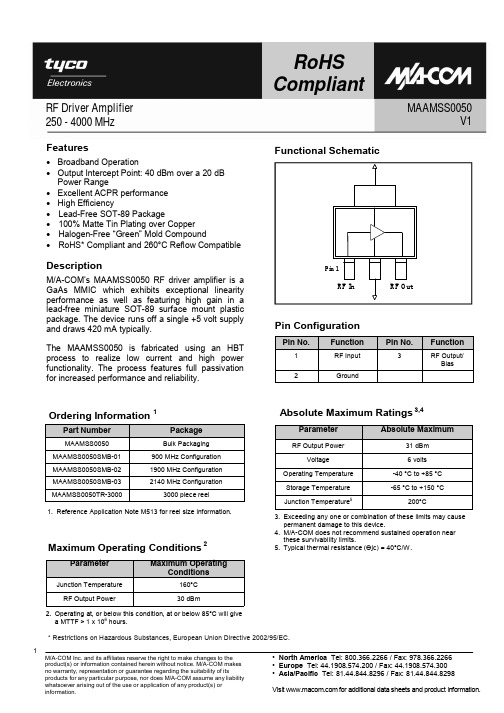
M/A-COM’s MAAMSS0050 RF driver amplifier is a GaAs MMIC which exhibits exceptional linearity performance as well as featuring high gain in a lead-free miniature SOT-89 surface mount plastic package. The device runs off a single +5 volt supply and draws 420 mA typically.
Visit for additional data sheets and product information.
元器件交易网
RF Driver Amplifier 250 - 4000 MHz
900 MHz PCB Layout
RoHS366.2266 / Fax: 978.366.2266 • Europe Tel: 44.1908.574.200 / Fax: 44.1908.574.300 • Asia/Pacific Tel: 81.44.844.8296 / Fax: 81.44.844.8298
RoHS Compliant
Functional Schematic
MAAMSS0050 V1
Pin 1 RF In
RF Out
Pin Configuration
Pin No.
1
Function
RF Input
2
Ground
Pin No.
3
Function
RF Output/ Bias
Ordering Information 1
余热发电505说明

WOODWARD 505 说明一、概述WOODWARD 505 是美国WOODWARD 公司日本分公司生产的以微处理器为基础的数字式调节器。
根据每一台汽轮机的特性和参数对505进行组态。
505能接受转速传感器发送的频率信号, 经内部频率/电压转换器转换后与转速设定值比较, 产生相应的4-20mA电流信号, 输出给电液转换器(I/H or CPC), 电液转换器把电流信号转换成控制相应的二次油油压(0.15-0.45MPa),二次油油压控制错油门滑阀,进而控制调节汽阀开度;以达到控制蒸汽流量,调整汽轮机出力,使汽轮机运行在设定的转速。
汽轮机的复位、启动、低速暖机、高速暖机、升/降转速及汽轮机的超速试验均可以在505面板上完成。
也可以在就地柜上或者DCS系统上设置必要的按钮来完成上述功能。
但505面板操作有优先权。
505出现报警状况时,面板上的F1键会闪烁发出报警信号,但不会造成停机。
505出现跳闸状况时, 执行机构(ACT)的电流输出跃变为0mA, 调节汽阀关闭, 同时把跳闸信号传给保护系统(ETS), 通过停机电磁阀切断油路, 关闭速关阀, 断开蒸汽以保证汽轮机安全。
二、505技术参数以下的叙述以版本(Manual 85012)为例外形尺寸图为505的外形。
505的所有部件包容在一个NEMA4型钢制机壳中。
正面是LED显示屏和弹性按键;后面下方是端子排。
面板介绍图是505的面板, 由LED显示屏和30个按键组成。
LED可同时显示二行, 每行24个字符,可在组态和运行时显示和监视参数。
30个上按键的功能介绍如下:翻页键:键盘中央的大菱形键,菱形的四个角上各标有一个箭头。
,:在编程或运行模式下使功能块显示左、右移动。
▲,▼:在编程或运行模式下使功能块显示上、下移动。
选择键:SELECT 键用于505显示器上行或下行变量的控制选择。
符号@用于指示哪一行(变量)能通过ADJ 键来进行调整。
只有当上、下均有可调整变量(动态、阀门标定模式)时,才会使用SELECT 键和@符号来决定哪一行的变量可被调整。
蓝外设备MAA-S500的安装指南说明书

Malware Analysis Appliance: MAA-S500 Series
1 3 Unpack the Appliance
Unpack the shipment package and verify the contents of the box.
The Blue Coat MAA-S500 series appliance ships with the following components:
2. Assemble the slide-rails (Figure 6): a. Loosely attach Rail_C to Rail_A. The precise attachment location depends on how far Rail_C must be extended (or retracted) to fit your specific equipment rack model. It might be necessary to remove Rail_C from Rail_A to determine the proper installation length for your network rack. Temporarily mount Rail_C to Rail_A by doing the following: 1. Approximate the slide-rail installation length by lining up the front and rear mounting faces against the equipment rail. Be sure that the slide-rail mounting faces are on the outside of the equipment rack vertical rails. 2. Temporarily install (3) M3 screws through the slotted hole located on Rail_C after the installation length has been determined. Be sure to install the screws equidistantly to distribute the loads placed on the rail. b. Repeat step 2a for the opposite slide-rail.
OM-5000系列产品说明书

Molded Transition Joint Thermocouple Probes sold separately, $20 ea.,Models KTIN-14U-12,JTIN-14U-12 and TTIN-14U-12 shown.See page A-83.ߜAutomatically Measures,Monitors and Records Temperatures and Voltages ߜWallmount and BenchtopStyles AvailableߜEasy 10 or 40 ChannelsProgramming from KeyboardߜBuilt-in 24 Character Printer ߜRS-232 Communication ߜGlobal High and LowAlarm RelaysߜExternal Print TriggerߜData Cache with 14.5 KByteBuffer Memory Standard ߜComprehensiveWindows-Based Software for Analyzing, Documenting,Graphing and EasyReporting of the ResultsOM-5200A Series Wall Mount Units$3395Basic UnitOM-5100A Series Benchtop Units$3395Basic UnitThe OM-5000 Series are compact dataloggers that measure, display, record and print data from a varietyof inputs including thermocouples and voltage sources. For applications in various operating environments, models are available for either wall mounting or benchtop use. An exceptionally bright display and high resolution printer assure easy operation of the units. Using a complete alphanumeric character set, the16-digit vacuum fluorescent display prompts the user while programming the unit. When logging a process, the display shows time, channel number and the value of the reading with units. The display is also used to view the contents of the 14.5 kilobyte buffer data cache which is capable of holding up to 7250 data points. The data cache, buffer memory provides temporary storage to allow reviewing data before printing or downloading. The integral thermal printer provides excellent sharpness and readability and an expanded24 character line.Completely programmable from the keyboard, input parameters include: current data, time and print interval, the contents and format of the printout, the configuration of each channel by sensor type, the number of channels scanned and skipped, scaling of the display, high and low alarms, engineering units, default unit of temperature, and nonvolatile storage of the system in an electrically programmed RAM.The OM-5000’s will accept a wide variety of inputs:7 different types of thermocouples as well as voltage inputs (0 to 2 V) in any channel. Temperature resolution is 0.1 degree, and voltage resolution is 100 microvolts at 2 volts. To output data, two-way RS-232 communication is standard. An optional alarm board, OM-5000-ARB, will control up to 10 channels with1 high and 1 low relay per channel with indicator lights. The relay board, which includes power supply, can be daisy-chained to 40 channels. All accessory alarm inputs and outputs are optically isolated or employ relay contact closures.SpecificationsTHERMOCOUPLE INPUTSTypes:J, K, T, E, R, S, BInput Impedance:10 mΩLead Resistance Effect:Less than 20 µV per 400 ΩCold Junction Compensation:0 to 50°C (32 to 122°F) Thermocouple Short to AC Protection:120 Vac Common Mode Voltage:1500 VacCommon Mode Rejection Ratio: dc to 50/60 Hz: 160 db Normal Mode Rejection Ratio: 50/60 Hz: 50 dbCold Junction Error:0.5°C (0.9°F) max, 10 to 40°C (50 to 104°F) VOLTAGE INPUTSRange:±2 VCMRR:>120 dB, dc to 60 HzNMRR:>75 dB CMV: 1500 VacInput Impedance:1 mΩBias Input Current:7 nAOvervoltage Protection:240 Vac, RMS Resolution:100 µV ChannelsLog Interval PrintoutConfiguration Printoutscanning (7)40 channels)channels (C)Userassignableunits (up to 3charactersLog intervalprintout(23 hrs 00min 00 sec)Dwell time (2sec/channel) ThermocoupleTime{{{{No alarmHigh valuealarmSoftwareRejectionfrequencyCacheinstalled(yes)Alarm Points PrintoutOM-5000 Series AccessoriesOMEGACARE SM extended warranty program is available for models shown on this page. Ask your salesrepresentative for full details when placing an order.OMEGACARE SM covers parts, labor and equivalent loanersThe OM-5000 series has beendiscontinued. Please see the DR130 as a possible alternative or contact ourCANADA www.omega.ca Laval(Quebec) 1-800-TC-OMEGA UNITED KINGDOM www. Manchester, England0800-488-488GERMANY www.omega.deDeckenpfronn, Germany************FRANCE www.omega.fr Guyancourt, France088-466-342BENELUX www.omega.nl Amstelveen, NL 0800-099-33-44UNITED STATES 1-800-TC-OMEGA Stamford, CT.CZECH REPUBLIC www.omegaeng.cz Karviná, Czech Republic596-311-899TemperatureCalibrators, Connectors, General Test and MeasurementInstruments, Glass Bulb Thermometers, Handheld Instruments for Temperature Measurement, Ice Point References,Indicating Labels, Crayons, Cements and Lacquers, Infrared Temperature Measurement Instruments, Recorders Relative Humidity Measurement Instruments, RTD Probes, Elements and Assemblies, Temperature & Process Meters, Timers and Counters, Temperature and Process Controllers and Power Switching Devices, Thermistor Elements, Probes andAssemblies,Thermocouples Thermowells and Head and Well Assemblies, Transmitters, WirePressure, Strain and ForceDisplacement Transducers, Dynamic Measurement Force Sensors, Instrumentation for Pressure and Strain Measurements, Load Cells, Pressure Gauges, PressureReference Section, Pressure Switches, Pressure Transducers, Proximity Transducers, Regulators,Strain Gages, Torque Transducers, ValvespH and ConductivityConductivity Instrumentation, Dissolved OxygenInstrumentation, Environmental Instrumentation, pH Electrodes and Instruments, Water and Soil Analysis InstrumentationHeatersBand Heaters, Cartridge Heaters, Circulation Heaters, Comfort Heaters, Controllers, Meters and SwitchingDevices, Flexible Heaters, General Test and Measurement Instruments, Heater Hook-up Wire, Heating Cable Systems, Immersion Heaters, Process Air and Duct, Heaters, Radiant Heaters, Strip Heaters, Tubular HeatersFlow and LevelAir Velocity Indicators, Doppler Flowmeters, LevelMeasurement, Magnetic Flowmeters, Mass Flowmeters,Pitot Tubes, Pumps, Rotameters, Turbine and Paddle Wheel Flowmeters, Ultrasonic Flowmeters, Valves, Variable Area Flowmeters, Vortex Shedding FlowmetersData AcquisitionAuto-Dialers and Alarm Monitoring Systems, Communication Products and Converters, Data Acquisition and Analysis Software, Data LoggersPlug-in Cards, Signal Conditioners, USB, RS232, RS485 and Parallel Port Data Acquisition Systems, Wireless Transmitters and Receivers。
梅兰日兰Galaxy5000技术说明书

以及更高操作安全性(再充电<11小时) 输入电压从250V到470V,可处理受干扰的配电系统。 超强的过载能力及辨别能力 发电机组启动过程中的输入电流限制 多种语言、图形显示、高分辨率四分之一VGA Digibat实现电池数字监控(计算实际后备时间及电池剩余使用寿
4. 功能.......................................................................................................21
4.1 主要标准功能..............................................................................................................21 4.2 可用选件.....................................................................................................................21
3.2 通过并机连接三台或四台UPS机组实现有源冗余...................................................19
3.3 用于更大功率的并机连接(无冗余)............................................................................20 3.4 外部旁路....................................................................................................................20
02-SAMSS-005

Previous Issue: 5 April 2006 Next Planned Update: 1 December 2009Page 1 of 13 Primary contact: Anezi, Mohammed Ali on 966-3-8746122Materials System Specification02-SAMSS-0053 July 2007 Butt Welding Pipe FittingsMaterials and Corrosion Control Standards Committee MembersAnezi, Mohammed Ali, ChairmanRumaih, Abdullah Mohammad, Vice ChairmanAbdul Hadi, Abdul Latif IbrahimBannai, Nabeel SaadBuraiki, Iyad AbdulrazzakBurgess, Brian WayneCruz, Czar Ivan TecsonKermad, AbdelhakLobley, Graham RusselMehdi, Mauyed SahibMoore, Mark AndrewMugbel, Wajdi MohammadNasri, Nadhir IbrahimNiemeyer, Dennis CharlesNuaim, Tareq AbdulazizOmari, Ahmad SalehRao, SanyasiTems, Robin DouglasSaudi Aramco DeskTop StandardsTable of Contents1 Scope (2)2 Conflicts and Deviations (2)3 References (2)4 Purchase Order Information (4)5 Design (4)6 Materials (6)7 Welding (8)8 Heat Treatment (9)9 Inspection and Testing................................. 10 10 Product Marking, Coating,Packing and Documentation (12)Next Planned Update: 1 December 2009 Butt Welding Pipe Fittings1 Scope1.1 This Specification supplements the requirements of ASME B16.9, ASTM A234for Grade WPB wrought carbon steel pipe fittings, and MSS SP-75 for highstrength fittings. Normally, it only applies to fittings that are purchased "loose."This Specification does not apply to fittings installed on equipment that isengineered, manufactured, and tested prior to delivery to Saudi Aramco unlessspecifically invoked in the Purchase Order.1.2 Cast fittings, stainless steel and corrosion-resistant alloy pipe fittings, and pipebends with a radius three times the diameter (3D) or greater are excluded fromthe scope of this specification.1.3 Fittings purchased in accordance with the requirements of this Specification aredeemed to be suitable for wet, sour services without additional testing orcertification.2 Conflicts and Deviations2.1 Any conflicts between this specification and other applicable Saudi AramcoMaterials System Specifications (SAMSSs), Engineering Standards (SAESs),Standard Drawings (SASDs), or industry standards, codes, and forms shall beresolved in writing by the Company or Buyer Representative through theManager, Consulting Services Department of Saudi Aramco, Dhahran.2.2 Direct all requests to deviate from this specification in writing to the Company orBuyer Representative, who shall follow internal company procedure SAEP-302and forward such requests to the Manager, Consulting Services Department ofSaudi Aramco, Dhahran.3 ReferencesThe selection of material and equipment, and the design, construction, maintenance, and repair of equipment and facilities covered by this specification shall comply with thelatest edition of the references listed below, unless otherwise noted.3.1 Saudi Aramco ReferencesSaudi Aramco Engineering ProcedureObtaining a Waiver of aSAEP-302 InstructionsforMandatory Saudi Aramco EngineeringRequirementNext Planned Update: 1 December 2009 Butt Welding Pipe FittingsSaudi Aramco Materials System SpecificationWeld Neck Flanges for Low andSteel02-SAMSS-011 ForgedIntermediate Temperature ServiceSaudi Aramco Inspection RequirementsForm 175-026100 Butt Welding Pipe Fittings3.2 Industry Codes and StandardsAmerican Society of Mechanical EngineersASME B16.9 Factory-made Wrought Steel Butt WeldingFittingsASME B16.25 Butt Welding EndsASME B16.28 Wrought Steel Butt Welding Short Radius Elbowsand ReturnsASME B16.49 Factory-made Wrought Steel ButtweldingInduction Bends for Transportation andDistribution SystemsASME B31.3 Process PipingASME SEC II Specification for Welding Rods, Electrodes, andFiller MetalsASME SEC VIII Rules for Construction of Pressure VesselsASME SEC IX Qualification Standard for Welding and BrazingProcedures, Welders, Brazers, and Weldingand Brazing OperatorsAmerican Society for Testing and MaterialsASTM A234/A234M Standard Specification for Piping Fittings ofWrought Carbon Steel and Alloy Steel forModerate and Eleveated TemperaturesASTM A370 Standard Test Methods and Definitions forMechanical Testing of Steel ProductsASTM A860/A860M Standard Specification for High-Strength Butt-Welding Fittings of Wrought High-Strength,Low-Alloy SteelASTM A956 Standard Test Method for Leeb Hardness Testingof Steel ProductsNext Planned Update: 1 December 2009 Butt Welding Pipe Fittings ASTM A960 Standard Specification for Common Requirementsfor Wrought Steel Piping FittingsASTM E165 Standard Test Method for Liquid PenetrantExaminationASTM E92 Test Method for Vickers Hardness of MetallicMaterialsAmerican Welding SocietyAWS A5.01 Filler Metal Procurement GuidelinesAWS A5.XX Specifications for Welding Filler Metals (Series ofSpecifications)Compressed Gas AssociationCGA G6.2 Specification for Carbon DioxideCGA G11.1 Specification for ArgonManufacturers Standardization SocietyMSS SP-75 Specification for High Test Wrought Butt-WeldingFittingsInformationOrder4 PurchaseThe following information shall be included in the Purchase Order:a) Type of fittingb) Nominal size of fittingc) Grade or specified minimum yield strength of fitting materiald) Nominal size, wall thickness or schedule and end details of pipe to be matchede) Material specification of matching pipef) Wall thickness of lap-joint stubs; if applicableg) Additional material and testing requirements; if applicableh) Charpy impact testing requirements, if applicablei) Export packing, marking, and shipping details5 DesignRating5.1 PressureNext Planned Update: 1 December 2009 Butt Welding Pipe Fittings5.1.1 Design and pressure rating of ASTM A234 Grade WPB fittings shall beestablished by proof testing per ASME B16.9 Section 9 or bymathematical stress analysis per ASME B31.3 Para. 304.7.2(d).5.1.2 Design and pressure rating of MSS SP-75 fittings shall be in accordancewith that specification. In addition, for elbows larger than NPS 16, thewall thickness shall comply with ASME B31.3 Para. 304.2.1 or ASMEB16.49 Para. 2.2. The thickness of the remainder of the fitting may beincreased to equal the required thickness of the intrados (inner radius or"crotch").Dimensions5.2 MainThe pipe fittings covered by this specification shall have dimensions as specifiedin ASME B16.9, ASME B16.28 or MSS SP-75 as applicable.Any exceptions shall be indicated in the Purchase Order.Welds5.3 CircumferentialCircumferential welds are not allowed except to attach extensions such as thosementioned in Para. 5.4 and straight tangent ends that are specified in thepurchase order. Circumferential welds are never allowed in the crotch area offittings.5.4 Tees and Reducing TeesThe branch outlet of tees shall be extruded or forged to the run and shall have asmoothly curved transition between run and branch. Welded-on branchconnections (set-on or stub-in) are prohibited. However, lengthening of anextruded outlet by means of a circumferential weld in the cylindrical part of thebranch will be permitted.When tees are fabricated from plate, the weld seams shall be parallel to the axesof the run and the branch.5.5 ReducersConcentric and eccentric reducers shall have smoothly curved wroughttransitions and parallel ends (ASME shape) unless a conical shape has beenspecified in the Purchase Order.Reducers shall have a nominal wall thickness which is at least equal to thespecified nominal wall thickness of the matching pipe (of equal specifiedminimum yield strength) at the large end.Next Planned Update: 1 December 2009 Butt Welding Pipe Fittings ASME shape reducers not listed in ASME B16.9 or MSS SP-75 shall bedesigned in accordance with ASME B31.3, paragraph 304.6 for a designpressure permitted by the matching pipe.Conical reducers are only permitted when so specified in the Purchase Order.The included angle shall not exceed 12 degrees.Exception:An included angle of maximum 15 degrees is allowed when the reducer isconcentric, has two cylindrical ends with a minimum length of 50 mm, andsmoothly finished circumferential welds.5.6 Lap-Joint Flange Stub EndsThe wall thickness of stub ends for lap-joint flanges shall be as specified in thePurchase Order and the welding end prepared by internal taper boring to matchthe specified pipe. Lap-joint flange stub ends (weld ends) for sizes larger thanNPS 24 are covered by 02-SAMSS-011 and related standard drawings.Designs5.7 SpecialSpecial designs, such as nonstandard shapes and dimensions, will be consideredwhen the Vendor can prove that similar fittings have been successfully tested bymeans of an actual bursting test in accordance with ASME B16.9 or MSS SP-75. The design shall be approved in writing by the Saudi Aramco ConsultingServices Department.5.8 Butt Welding EndsUnless otherwise specified in the Purchase Order, the butt welding ends shall bein accordance with the requirements of ASME B16.25 and match the beveledend of the pipe specified in the Purchase Order.6 Materials6.1 GeneralBoron content shall be shown in the heat analysis or product analysis and shallnot exceed 0.0005%.FittingsWPB6.2 Grade6.2.1 Material shall conform to the requirements of ASTM A234/A234MGrade WPB, including ASTM A960 Supplementary Requirements S50"Product Analysis", S51 "Tension Test" and S57 "Hardness Test".Next Planned Update: 1 December 2009Butt Welding Pipe Fittings Note:For Supplementary Requirement S50, a heat analysis may be substitutedfor the product analysis except for welding material.6.2.2 High strength starting stock shall not be used for Grade WPB fittingswithout prior, written permission from the CSD. In no case shall theactual yield strength of the finished fittings exceed 440 MPa (63,817psi). All other requirements for WPB fittings shall be met.6.2.3 The carbon equivalent shall not exceed 0.42% when calculated according to the formula:()()CE (IIW) = C Mn 6Cr Mo V 5Ni Cu 15++++++ (1) 6.3 High Strength Fittings (≥ 42,000 psi specified minimum yield strength)6.3.1 With the exception of the chemical composition requirements inparagraph 6.3.2 below, the high strength material shall conform to therequirements of MSS SP-75, including Supplementary RequirementsSR-4 (hardness and nickel content limitations, except parent metal nickelshall be limited per paragraph 6.3.2 below), SR-5 (actual yield strengthlimitation), and SR-10 (more restrictive chemical requirements andcarbon equivalent).6.3.2 Chemical composition shall be in accordance with the requirements ofASTM A860/A860M, Paragraph 7.6.4 The vendor shall provide a certified material test report listing the actual resultsof the chemical analysis, mechanical properties, notch toughness properties, heat treatment, nondestructive examination, and any special tests required by thePurchase Order.6.5For Sour service, the following additional requirements are applicable forwelded fittings fabricated from plate or strip:6.5.1 The steel shall be vacuum degassed.6.5.2 The maximum sulfur shall be 0.002%. Sulfur content up to andincluding 0.005% is acceptable if the steel is calcium treated forinclusion shape control. Typical calcium content is between one andthree times the sulfur content.Next Planned Update: 1 December 2009 Butt Welding Pipe Fittings 7 Welding7.1 General7.1.1 Complete Welding Procedure Specifications (WPS's) and ProcedureQualification Records (PQR's) shall be made available for review by theSaudi Aramco inspector.7.1.2 All Welding Procedure Specifications (WPS's) and ProcedureQualification Records (PQR's) shall be written in English and conform tothe applicable Code.7.2 Processes7.2.1 The following processes are approved for use:•Shielded Metal Arc Welding (SMAW)•Gas Tungsten Arc Welding (GTAW)•Submerged Arc Welding (SAW)•Gas Metal Arc Welding (GMAW) - Short Circuiting transfer shallnot be used.•Flux Core Arc Welding (FCAW) - Shall not be used for the root passon one sided groove welds.7.2.2 Automatic welding without the addition of filler material is notpermitted.7.3 WeldingConsumables7.3.1 Electrodes, filler wires, and fluxes shall conform to the requirements ofthe BPV, ASME SEC II, Part C, identical to the AWS A5.XXspecification series. Other consumables may be used only with thespecific approval of Saudi Aramco.7.3.2 Properly conditioned low-hydrogen electrodes shall be used for allfittings when the wall thickness exceeds 13 mm.7.3.3 A change in filler metal deposit chemistry from A-No. 1 of BPV, ASMESEC IX to A-No. 2 and vice-versa is not permitted withoutrequalification.7.3.4 Active Submerged Arc Welding fluxes shall not be used.Next Planned Update: 1 December 2009 Butt Welding Pipe Fittings7.3.5 Shielding gases shall conform to the appropriate Compressed GasAssociation (CGA) specification(s).7.4 Welding Procedure Qualifications7.4.1 GeneralFor any SAW flux, GMAW electrode, or FCAW electrode used forprocedures which require Charpy Impact testing and all FCAWelectrodes for fittings shall be restricted to the specific brand, type andmaximum size as used for the PQR. The brand name and type of flux orelectrode shall be specified on both the WPS and PQR.7.4.2 Hardness TestingHardness traverses conducted in accordance with ASTM E92 shall bemade on a full-thickness, transverse cross-section of the weld that hasbeen mounted, polished to metallographic quality, and etched. Twotraverses shall be made. One shall be within 1.0 mm from the O.D.surface and one within 1.0 mm from the I.D. surface. Each traverse shallconsist of at least two hardness indentations in each of the followinglocations:a) weldmetalb) heat affected zone on each side of the weld andc) parent metal on each side of the weld.Only Vickers 5 kg or 10 kg hardness testers shall be used. Hardness ofbase metal, HAZ, and weld metal shall not exceed 207 HV for Grade Bfittings and 250 HV for high strength fittings.7.5 Repairs7.5.1 Cracks shall be repaired only if approved by the Saudi Aramco inspector.7.5.2 Unsuccessful weld repairs after the second attempt shall be completelycut out and replaced.Treatment8 HeatHeat treatment after all forming and welding processes are completed is required for all fittings.8.1 All Grade WPB fittings supplied in accordance with this specification shall benormalized as defined in ASTM A234. All high strength fittings shall beNext Planned Update: 1 December 2009 Butt Welding Pipe Fittings normalized, normalized and tempered, or quenched and tempered as defined inMSS SP-75. Stress relief heat treatments are not acceptable, even if permitted inASTM A234/A234M or in MSS SP-75.8.2 Seamless Grade WPB fittings for which the final forming operation iscompleted at a temperature above 620°C and below 980°C need not besubsequently heat treated provided they are cooled in still air.8.3 Hot formed high strength fittings shall be cooled below the lower criticaltemperature prior to heat treatment.9 Inspection and Testing9.1 GeneralThe fittings are subject to inspection by the Saudi Aramco InspectionRepresentative per Saudi Aramco Inspection Requirement Form 175-026100attached to the Purchase Order.9.2 Visual Examination and Dimensional CheckGeneral appearance, workmanship and fit-up shall be acceptable in accordancewith ASME B31.3 Para. 344.2. Weld surfaces shall show a smooth contour.Dimensions of the fitting shall be checked against ASME B16.9, MSS SP-75 orapproved Vendor's Drawings.9.3 Dye Penetrant or Magnetic Particle TestingAll butt weld ends shall be tested using one of the following methods:•dye penetrant (color contrast penetrant) in accordance with ASTM E165.Acceptance criteria shall be per "Boiler & Pressure Vessel Code," ASMESEC VIII D1, Appendix 8.•magnetic particle tested in accordance with ASME SEC VIII D1, Appendix 6.9.4 RadiographyAll welds in fabricated fittings shall be 100 percent radiographed in accordancewith "Boiler and Pressure Vessel Code," ASME SEC VIII D1, paragraph UW-51.TestsHardness9.5 Production9.5.1 Hardness tests shall be conducted on a minimum of 20% of seamlessfittings forged at temperatures above 620°C and 100% of seamlessfittings forged at 620°C or lower. Hardness tests shall be conducted onNext Planned Update: 1 December 2009 Butt Welding Pipe Fittings 100% of all welded construction fittings regardless of forgingtemperature.9.5.2 Hardness testing shall be conducted using either a bench-top hardnesstester calibrated to ASTM (or equivalent) standard hardness test blocksor a portable hardness tester that has been approved in writing by SaudiAramco. To be approved, the portable hardness tester must bedemonstrated to give repeatable results within 10% of those obtainedwith the calibrated bench-top hardness tester on fittings similar to theproduction fittings. If the difference in readings between the portableand bench-top testers exceeds 5%, the hardness acceptance criterion shallbe adjusted (lowered) by the maximum amount of the difference (forexample, lowered by 6%, 8%, or 10%). The calibrations must becertified by an independent, third-party agency or by the Saudi AramcoInspection representative.9.5.3 A minimum of three hardness indentations shall be made on the parentmetal of each fitting, with the test locations spaced evenly across thepiece being tested. (For fittings 2-inch and smaller, only twoindentations are required.) For welded fittings, an additional threehardness indentations shall be made, evenly spaced, along the weld.Where accessible, the weld metal hardnesses should be measured on theI.D. surface of the fittings.9.5.3.1 If any single indentation exceeds the allowable hardness limit,two additional hardness indentations shall be taken within 25mm of it, and the three hardness values shall be averaged. Ifthe average exceeds the allowable limit, the fitting shall berejected, and all the other fittings from the same heat shall be100% hardness tested, even if not otherwise required inparagraph 9.5.1.9.5.3.2 The difference between the highest and lowest hardnessreadings in the parent metal shall not exceed 20 HB. Inaddition, for welded fittings, the difference between the highestand lowest hardness readings in the weld metal shall notexceed 20 HB. If the difference exceeds 20 HB for either theparent metal or the weld metal hardness values, the fittingsshall be rejected, and all other fittings from the same heat shallbe 100% hardness tested, even if not otherwise required inparagraph 9.5.1. For the purpose of determining the spread ofHB readings, a set of three indentations at the same locationmay be substituted for any single reading and the average ofthe three used instead of the single reading.Next Planned Update: 1 December 2009 Butt Welding Pipe Fittings9.5.3.3 At the manufacturer's option, all fittings that have failed thehardness test requirements in paragraphs 9.5.3.1 and/or 9.5.3.2can be re-normalized and hardness tested again. Fittings thatpass the hardness test requirements and the strengthrequirements after re-normalizing may be accepted. Fittingsthat fail a second time shall be permanently rejected.9.5.4 If a portable hardness tester of the Leeb (rebound) type is used, itsapplication shall be in accordance with ASTM A956.9.6 Charpy Impact Testing9.6.1 Charpy impact testing requirements for fittings in Grades WPHY-42 andhigher strength are given in MSS SP-75. Grade WPB fittings do notrequire impact testing unless specified in the Purchase Order.9.6.2 For welded fittings, testing shall be performed on the base metal, heat-affected zone, and the weld metal. The weld metal and heat-affectedzone impact test specimens shall be transverse to the weld axis.9.6.3 Impact test procedures and apparatus shall conform to the applicableparagraphs of ASTM A370.9.6.4 The test temperature and the minimum Charpy energy requirements shallbe specified in the Purchase Order if different from the requirements inPara. 9.6.1.10 Product Marking, Coating, Packing and Documentation10.1 Fittings per ASTM A234/A234M WPB shall be marked in accordance withASME B16.9, paragraph 4.10.2 Fittings per MSS SP-75 shall be marked per MSS SP-75, paragraph 17. Inaddition, the carbon equivalent shall also be marked on the O.D. of the fitting.10.3 After inspection by Saudi Aramco's Inspection Representative, unless otherwisespecified in the Purchase Order, fittings shall be supplied with a protectivecoating that does not hide markings or surface defects. This temporary coating,combined with appropriate packing, must protect against corrosion during oceanshipment. The coating shall be hard and dry. It can be either a clear coating or athin opaque coating. Except for clear coatings, the maximum dry film thicknessshall be 0.076 mm. The fitting's normal stamped markings must be readable.10.4 The welding ends shall be coated with an aluminum-flake weldable primer("Deoxaluminite" or "Bloxide" or other brand approved by Saudi AramcoNext Planned Update: 1 December 2009 Butt Welding Pipe Fittings Consulting Services Department) or a coating that is easily strippable and doesnot leave a residue that interferes with welding. The maximum dry filmthickness of a weldable coating shall not exceed 0.050 mm. A welding endstrippable coating is allowed to be any thickness. Examples of strippablecoatings include high-build vinyl, urethane, PVC, or strippable tape appliedbefore a coating.10.5 All fittings must be protected from mechanical damage. Welding ends must beprotected with suitable wood, plastic, or metal covers. Fittings must bepackaged in steel-banded wooden crates or secured to skids.Note:If fittings up through 6-inch size are securely packaged in the wooden crates sothat they cannot shift during shipment and damage the welding bevels, theseparate covers are not required.10.6The results of all tests required in this Specification shall be reported. Thereporting documentation shall be in the English language and three copies shallbe provided.SummaryRevision28 February 2005 Editorial revision to affirm the contents, update the referenced paragraphs and committeelist, and changed the "Next Planned Update."5 April 2006 Minor revision.3 July 2007 Editorial revision to delete Section 11.。
面向支持系统的飞机维护工作手册 AMTOSS
48安装测试/支持设备
在飞机、系统、单元上使用的用来确定系统、部件的状态和位置的状态测试设备产品的安装。测试设备诸如,空速管静压测试仪、飞行控制系统调整(水平测量)象限仪等。
49没有使用
50器材、飞机移交
51发运
任何零件、子组件、部件或组件从包装到运送到目的地的活动。
52接收
任何引入的零件、子组件、部件或组件的接收活动。
53打包装
安装零件、子组件、部件或组件到装运容器。还包括管路的封盖和堵塞的安装等。
54解包装
从装运容器卸下零件、子组件、部件或组件。包括所有保护材料的拆除。
55存储//返回到可用
存储是指在不使用期间,零件、子组件、部件或子组件的安全保存。可能要求单元服务和特殊的手工。
32机加工、铰、打磨
获得期望的形状的过程,通过磨削、车床车削、镗孔、铰孔、拉削、铣磨、钻孔、精磨、珩磨,、填料、磨光、抛光、切割、成形、模锻冲压、冲裁、电化学机械加工ECM、电火花加工(EDM)等来完成的工作。
33复合材料修理
通过手工的0级切削、手工钻孔、手工抛光、手工磨削、手工精磨、手工铆接、手工倒圆角或手工弯成型材料、切削和修补补丁、焙烧、精轧、手工砂纸打磨、刮削、盲孔加工、手工攻螺纹、安装螺旋状的线圈衬垫、加热或冷却零件等修理复合材料。
27超声波检查
通过使用接触脉冲回波的超声波技术检查表面的裂纹、孔隙、夹杂物或其他不均匀的材料结构。
28特殊的,专门检查
是指不包含在21~27、29中涉及的检查方法。
29孔探检查
指需要使用孔探设备的任何检查。
30纠正,修理
31焊接,硬焊
通过氧炔焊、电阻焊、点焊、炉铜焊、吹管铜焊、感应(高频)钎焊、电子束焊、等离子体电弧焊、硬钎焊。这些分类包括表面硬化处理(渗碳、淬火、镀层)。
SMD 510 magazine 说明书

ORIGINAL OPERATING INSTRUCTIONSSMD510magazineIt is essential that the operating instructionsare read before the tool is operated for thefirst time.Always keep these operating instructionstogether with the tool.Ensure that the operating instructions arewith the tool when it is given to otherpersons.1These numbers refer to the corresponding illustra-tions.The illustrations can be found on the fold-outcover pages.Keep these pages open while studyingthe operating instructions.Operating controls and parts of the magazine1@Depth gauge;Screw length adjustment button=Screw length marks%Screwdriving depth adjustment thumbwheel&Release buttons(Strip guide)Transport latch+Lockbutton for sustained operation§Strip releaseDANGERDraws attention to imminent danger that could leadto serious bodily injury or fatality.WARNINGDraws attention to a potentially dangerous situationthat could lead to serious personal injury or fatality.CAUTIONDraws attention to a potentially dangerous situationthat could lead to slight personal injury or damage tothe equipment or other property.NOTEDraws attention to an instruction or other usefulinformation.Warning signsGeneralwarningWarning:electricity1Obligation signs Wear eye protection Wear a hard hat Wear ear protection Wear protective glovesSymbols Return waste material for recycling.Read theoperatinginstructionsbefore use.Location of identification data on the toolThe type designation and the serial number arestamped on the rear of the magazine.Make a noteof this data in your operating instructions and al-ways refer to it when making an enquiry to your Hiltirepresentative or service department.Type:Serial no.:The SMD 50 m agazine is an accessory used for driving collated screws.The magazine is suitable for use with the Hilti SF 4000/SF 4000‑A /SD 2500/SD 4500/SD 5000/SD 5000‑A22/SD 4500‑A18and SD 45screwdrivers.The magazine and Hilti screwdrivers are optimally matched to each other.In the safety rules in these operating instructions,the designation “power tool”refers to the magazine.Modification of the power tool is not permissible.Observe the information printed in the operating in-structions concerning operation,care and mainten-ance.To avoid the risk of injury,use only genuine Hilti accessories and insert tools.The power tool and its ancillary equipment maypresent hazards when used incorrectly by untrained personnel or when used not as directed.The power tool is designed for professional use and may be operated,serviced and maintained only by trained,authorized personnel.This personnel must be informed of any special hazards that may be encountered.The power tool and its ancillary equip-ment may present hazards when used incorrectly by untrained personnel or when used not as directed.The working environment may be as follows:con-struction site,workshop,renovation,conversion or new construction.Working on materials hazardous to the health (e.g.asbestos)is not permissible.1Magazine1S ‑MBL 116PH2bit1Operating instructions1Cardboard boxS ‑MBL 116PH2bitSME extension2SMD 50 m agazine 22Magazine unit,complete 3829053Depth gauge 5.Technical dataRight of technical changes reserved.Magazine SMD 50Weight Without screwdriver,Without screw strip:0.77 l b /0.35kg Length Contact pressure to 40N (4.0kp)Screw capacity (screws per strip)50Suitable drywall screw types SMD 50Length Thread inside diameter Head diameter Drive type Philips no.2(S ‑MBL 116PH2)Philips no.2can be driven with the following Hilti screwdrivers SF 4000/SF 4000‑A /SD 5000/SD 2500/SD 4500/SD 5000‑A22/SD 4500‑A18/SD 45a)Stay alert,watch what you are doing and use common sense when operating a power tool.Do not use a power tool while you are tired or under the influence of drugs,alcohol or medication.A moment of inattention while operating power tools may result in serious personal injury.b)Dress properly.Do not wear loose clothing or jewellery.Keep your hair,clothing and gloves away from moving parts.Loose clothes,jewellery or long hair can be caught in moving parts.c)Use safety equipment.Always wear eye pro-tection.Safety equipment such as dust mask,non-skid safety shoes,hard hat,or hearing pro-tection used for appropriate conditions will reduce personal injuries.a)Use the power tool,accessories and tool bits etc.,in accordance with these instructions and in the manner intended for the particular type of power tool,taking into account the working conditions and the work to be e of the power tool for operations different from those intended could result in a hazardous situation.b)Maintain power tools.Check for misalignment or binding of moving parts,breakage of parts and any other condition that may affect the power tool’s operation.If damaged,have the power tool repaired before use.Many accidents are caused by poorly maintained power tools.c)Store idle power tools out of the reach of children and do not allow persons unfamiliar with the power tool or these instructions to operate the37.3 i nches /186 m m1"–2"4232424Magazine spring 3876741/8...3/16 i nch /3…4.5mm5/16 i nch /7.5…8.6mmpower tool.Power tools are dangerous in the hands of untrained users.a)Observe the operating instructions and the safety rules contained for the magazine and the screw-driver used.b)Always work with the screwdriver running at maximum speed.Accordingly,use the switch lockbutton on the screwdriver.c)Do not hold the SMD 50magazine in the area of the depth gauge.d)Each screwdriving stroke must be completed infull.Interruption of the magazine stroke or releaseof pressure half way through the screwdrivingoperation may lead to malfunctions.e)Change the screw strip only when the screwdriveris switched off.f)Wear eye protection,especially when working overhead.g)Use only genuine Hilti S ‑MBL 116PH2bits.Check that the bits are in good condition.h)Use only genuine Hilti screw strips and screws.i)Always work at right angles to the surface of theworkpiece to be fastened.j)Store the screw strips in a straight position,asthey are in the original package.CAUTION Disconnect the screwdriver’s supply cord from the electric supply before fitting the magazine.1.Remove the depth gauge and bit holder from the screwdriver. 2.Fit the bit into the screwdriver.NOTE The bit clicks into position.3.Push the magazine onto the screwdriver in the desired working position until it is heard to en-gage.NOTE The magazine can be engaged on the toolin various positions (every 15°).NOTE Check to ensure that the screwdriver is setto “forward”rotation.1.Adjust the depth gauge to suit the length of the screws to be driven.2.Press the button and slide the depth gauge back or forward.3.Set the depth gauge to one of the 5length marks corresponding to the length of the screws.NOTE The correct screw length setting is very important for trouble-free magazine operation.1.Slide the screw strip through the guide and the channel until the first screw is in position at the mark or until the end of the strip is flush with the upper surface of the magazine at the exit opening.2.Check that the screw strip has engaged by tryingto pull it back gently.1.Set the optimum screwdriving depth by turningthe thumbwheel.2.Turning the thumbwheel counterclockwise causes the screw to be driven deeper.3.Drive a screw to test the screwdriving depthsetting.4.Readjust the setting if necessary.NOTE Each audible click of the thumbwheelcorresponds to an adjustment of 0.2mm (0.008inch).45.Turning the thumbwheel clockwise causes the screw to be driven less deeply.CAUTIONDisconnect the screwdriver’s supply cord from the electric supply.1.Release the strip retainer by pressing the transport latch. 2.Pull the screw strip back.NOTE Alternatively,the screw strip can be pulledupwards,out of the magazine,without pressingthe transport latch.CAUTIONDisconnect the screwdriver’s supply cord from theelectric supply before removing the magazine.The magazine can be removed by pressing the releasebuttons and,at the same time,pulling it away fromthe screwdriver.NOTE Dirt and dust (especially from plaster)may have an adverse effect on operation of the magazine.CAUTION Do not,under any circumstances,lubricate the magazine with mineral oil /grease or graphite sprays.This would increase the risk of malfunc-tions.Clean the magazine simply by blowing out the dirt and dust with compressed air.NOTE It is recommended that the magazine is cleaned by washing it out with warm water after a long period ofheavy use. 1.Remove the screw strip as described in the section “Moving the screw strip back”.2.Remove the magazine as described in the section “Removing the magazine from the screwdriver”.3.Press the release spring together with the aid ofpliers or a similar tool.The transport mechanism,including the depth gauge,can then be removed from the casing.You now have three assem-blies in your hand:the transport mechanism,the pressure spring and the casing.4.If necessary,the depth gauge can also be separ-ated from the other parts by pulling it out while pressing the screw length adjustment button.NOTE Take care to avoid pinching your fingers.5.The parts can then be cleaned thoroughly withwarm water.NOTE We recommend use of a nylon brush (an old toothbrush)to remove stubborn deposits.Assembly is carried out in the reverse order.Operate the transport movement once or twice tocheck that the magazine is functioning correctly aftercleaning and reassembly.5Most of the materials from which Hilti tools or appliances are manufactured can be recycled.The materials must be correctly separated before they can be recycled.In many countries,Hilti has already made arrangements for taking back old tools and appliances for recycling.Ask Hilti customer service or your Hilti representative for further information.Hilti warrants that the tool supplied is free of defectsin material and workmanship.This warranty is valid so long as the tool is operated and handled correctly,cleaned and serviced properly and in accordance with the Hilti Operating Instructions,and the technical system is maintained.This means that only original Hilti consumables,components and spare parts may be used in the tool.This warranty provides the free-of-charge repair orreplacement of defective parts only over the entire lifespan of the tool.Parts requiring repair or replace-ment as a result of normal wear and tear are not covered by this warranty.Additional claims are excluded,unless stringent na-tional rules prohibit such exclusion.In particular,Hilti is not obligated for direct,indirect,incidental or consequential damages,losses or expenses in connection with,or by reason of,the use of,or inability to use the tool for any purpose.Implied warranties of merchantability or fitness for a par-ticular purpose are specifically excluded.For repair or replacement,send the tool or related parts immediately upon discovery of the defect to the address of the local Hilti marketing organization provided.This constitutes Hilti’s entire obligation with regardto warranty and supersedes all prior or contempor-aneous comments and oral or written agreementsconcerning warranties.6*424721*424721Hilti CorporationLI-9494SchaanTel.:+423/2342111Fax:+423/2342965Hilti =registered trademark of Hilti Corp.,Schaan W 3739051000-Pos.31Printed in Liechtenstein ©2010Right of technical and programme changes reserved S.E.&O.424721/A。
美国(Magna)万能焊条
美国(Magna)万能焊条系列万能异种钢焊接焊条万能铸铁和钢焊接焊条万能异种金属间焊接焊条万能铜金属焊接焊条气焊万能 33F 高韧度, 适用于各钢类之气焊条焊金流动性与银焊条相似。
万能 51 适用于铝及铸锌件之修理, 对铝与铜之焊接尤佳, 可做铝之此型T接及搭接, 铝及异指类金属之焊接。
万能 55 本焊条是专门对铝, 铝合金, 铸铝而特吶设计的, 具备有此一种焊材可解决任何铝之焊接问题。
万能 66F 是一种附带药皮的高银含量全功能焊条,适用于维修应用,对几乎所有黑色及有色金属的焊接都有带腐蚀性的出众效果。
万能 67F 最幼细的, 涂以银质焊料之多用途焊枝为特殊之维修工作而配方。
万能 75F 一种多用途的青铜质合金, 用于铸铁和其它金属的焊接。
万能 77F 为焊接因磨损及破坏了的零件而设的超级敏感焊金。
万能 88C 自生熔剂超强力软焊焊合金, 并具超强抗腐蚀之万能合金。
电弧焊万能 8N12 多效的焊条用于焊接抗高温合金钢, 英高镍, 纯镍, 和所有镍合金. 可焊接50种以上的不同合金。
万能 100 是最经济且速度最快之开槽焊条。
万能 150 用来切割和穿洞。
万能 210 具有广泛用途之电焊枝。
万能 303 一种具有高效二相杆敷金属的焊条, 具有优越的抗裂作用。
万能 305 高强度可在任何位置施杆之电杆条,对T-型钢, 管道及圆形管与钢板之焊接最适用。
万能 307 钢合金焊枝。
万能 393 特佳流火烧焊, 防止腐蚀。
万能 395 特制的Duplex不锈钢焊条。
万能 400 完全是针对轧碎而设计, 有优越之填补率而节省许多焊条。
万能 401 用于一般耐冲击及耐磨耗。
万能 402 可耐非常强劲的冲击及锰钢的接合。
万能 403 含钦及铬合金乏耐磨炉条最耐高低重压之磨擦。
万能 404 密度高硬度均匀之碳化钨电焊条, 可作最耐磨损之硬化补面。
( 亦可用于气杆)万能 405 可堆填的焊条。
(强韧可机械加工火焰硬化)万能 440 高速工具钢焊条, 专为耐长期磨损刀刃而设的独有合金。
松下A5电机样本

ĿӬᄰ7ಪҮ٧ʿၸnj ŀឯҫॸࠃᬄᜈᎵᆷᝢࠪ̅'ᅮᫍϢႂಪᄉ
ͤnj
ቿՋ SNJO .4.& ۋႂ 8 ̾ʽ
ᄉణᰳᣀᤳ SNJOnj
NJǏ8 ளேඊǐ
ᣀᅽ </eN>
" ጆѴNJ.4.%ὉὉὉ
ͮᎵૈ̽ᤳऎ<SNJO> Ժԟஜ
Ԫఝథௐᫍ
ႂ
ᤁᣀ
Ϣൢ
ᤳ
ऎ
ኃܘᄝ
ኃܘᄝ ኃܘᄝ
థ
థ
థ
ܰᦉ࣯ҩᑞ
ѽၸܰᦉ࣯٧࠱ਆᄉܰᦉ࣯ᣀᅽਆϘҪڙ ˀᣀᅽૈ̽ᄰક๖ᄉழՓʼὋђ࠵࣯ᦉܰځᣀᅽᏪ࠭ ᒰᄉॕֽὋ̯ᏪᬋͯᤳऎNjђ࠵Үᄉҩᑞnj
ʿၸܰᦉ࣯
nj
4
MSMA 2kW MSME 2kW
〈例:MSM、MDM 时〉 系列 A4 A5 轻量化
MSM 1kW 4.5kg 3.5kg ▲1kg MSM 2kW 6.5kg 5.3kg ▲1.2kg MDM 1kW 6.8kg 5.2kg ▲1.6kg MDM 2kW 10.6kg 8.0kg ▲2.6kg
ႂຸуѣႂึં҃ҩᑞ Dž˝ൢଋႂຸௐځуѣႂึᤴᄉႂຸறᡸ٧Ѭ
றὋЮᎵ˿уѣႂึં҃ႂ٧nj
表1 适用线性标尺
并用
Sony Manufacturing Systems 株式会社制造
串行式(绝对值)
株式会社三丰制造
Sony Manufacturing Systems 株式会社制造
ൣݝὀ
$PNQBDU
ǗᣏΦ ǘ
ளࢹͺழก ளधԦᔆ ளधԦᎃᆉ٧
MORNSUN A05_XT-1WR3 电源说明书

1W,Fixed input voltage,isolated &unregulated dual outputPatent Protection RoHSFEATURES●Continuous short-circuit protection ●No-load input current as low as 5mA●Operating temperature range:-40℃to +105℃●High efficiency up to 83%●Compact SMD package ●Isolation voltage:1.5K VDC ●International standard pin-out●Meets UL62368,EN62368standards (Pending )A05_XT-1WR3series are specially designed for applications where an isolated voltage is required in a distributed power supply system.They are suitable for:pure digital circuits,low frequency analog circuits,relay-driven circuits and data switching circuits.Selection GuideCertificationPart No.Input Voltage (VDC)OutputEfficiency (%,Min./Typ.)@Full Load Max.CapacitiveLoad(µF)*Nominal (Range)Output Voltage(VDC)Output Current (mA)(Max./Min.)UL/CE (Pending)A0505XT-1WR35(4.5-5.5)±5±100/±1078/821200A0509XT-1WR3±9±56/±679/83470A0512XT-1WR3±12±42/±579/83220A0515XT-1WR3±15±34/±479/83220Note:*The capacitive loads of positive and negative outputs are identical.Input SpecificationsItemOperating ConditionsMin.Typ.Max.Unit Input Current(full load /no-load)5VDC input5VDC output--244/5257/10mA 9VDC/12VDC output --241/12254/2015VDC output--241/18254/30Reflected Ripple Current*--15--mA Surge Voltage (1sec.max.)5VDC input-0.7--9VDCInput Filter Filter capacitor Hot PlugUnavailableNote:*Reflected ripple current testing method please see DC-DC Converter Application Notes for specific operation.Output SpecificationsItemOperating ConditionsMin.Typ.Max.Unit Output Voltage Accuracy See tolerance envelope curve(Fig.1)Line RegulationInput voltage change:±1%---- 1.2%/%Load Regulation10%-100%load5VDC output--1015%9VDC output --81012VDC output --71015VDC output--610Ripple &Noise *20MHz bandwidth --3075mVp-p Temperature Coefficient Full load--±0.02--%/℃Short Circuit ProtectionContinuous,self-recoveryNote:*Ripple and noise are measured by “parallel cable”method,please see DC-DC Converter Application Notes for specific operation;General SpecificationsItemOperating ConditionsMin.Typ.Max.Unit Isolation Voltage Input-output,with the test time of 1minute and the leak current lower than 1mA1500----VDC Isolation Resistance Input-output,isolation voltage 500VDC 1000----M ΩIsolation Capacitance Input-output,100KHz/0.1V--20--pFOperating Temperature Derating when operating temperature up to 100℃,(see Fig.2)-40--105℃Storage Temperature -55--125Casing Temperature Rise Ta=25℃--15--Pin Welding Resistance Temperature Welding spot is 1.5mm away from the casing,10seconds ----300Storage HumidityNon-condensing ----95%RH Reflow Soldering Temperature*Peak temp.≤245℃,maximum duration time ≤60s at 217℃.Switching Frequency Full load,nominal input voltage --270--KHz MTBFMIL-HDBK-217F@25℃3500----K hoursMoisture Sensitivity Level (MSL)IPC/JEDEC J-STD-020D.1Level 2Note:*For actual application,please refer to IPC/JEDEC J-STD-020D.1.Physical SpecificationsCasing Material Black flame-retardant and heat-resistant plastic(UL94V-0)Dimensions 15.24*11.40*7.25mm Weight1.4g (Typ.)Cooling MethodFree air convectionEMC SpecificationsEMI CE CISPR32/EN55032CLASS B (see Fig.5for recommended circuit)RE CISPR32/EN55032CLASS B (see Fig.5for recommended circuit)EMSESDIEC/EN61000-4-2Air ±8kV ,Contact ±4kVperf.Criteria BProduct Characteristic Curve-10%-5%0+5%+10%+15%T y p .M i n .M a x .Output Current Percent (Nominal Input Voltage)O u t p u t V o l t a g e A c c u r a c yTolerance Envelope CurveFig.112080O u t p u t P o w e r P e r c e n t (%)Ambient Temp.()℃Safe Ope rating AreaFig.2Design ReferenceIf it is required to further reduce input and output ripple,a filter capacitor may be connected to the input and output terminals,see Fig.3.Moreover,choosing a suitable filter capacitor is very important,start-up problems may be caused if the capacitance is too large.Under the condition of safe and reliable operation,the recommended capacitive load values are shown in Table 1.The simplest device for output voltage regulation,over-voltage and over-current protection is a linear voltage regulator with overheat protection that is connected to the input or output end in series (see Fig.4).Vin +Vo 0V DCCinDC CoutCout -VoVin 0V +Vo DC DC-VoREGREGREGFig.4Recommended capacitive load value table (Table 1)Vin(VDC)Cin(µF)Vo (VDC)Cout(µF)54.7±54.7±9 2.2±121±1512.EMC solution-recommended circuitFig.5EMC recommended circuit value table (Table 2)Input voltage 5VDCOutput voltage(VDC)5/912/15EMIC1/C24.7µF /25V4.7µF /25VCY --1nF/2KVDCHEC C1206X102K202T JOHANSON 202R18W102KV4E C3Refer to the Cout in table 1LDM6.8µH 6.8µHNote:In the case of actual use,the requirements for EMI are high,it is subject to CY.3.For more information please find DC-DC converter application notes on Dimensions and Recommended LayoutNotes:1.Packing information please refer to Product Packing Information which can be downloaded from .TubePacking bag number:58210023,Roll Packing bag number:58210034;2.If the product is not operated within the required load range,the product performance cannot be guaranteed to comply with allparameters in the datasheet;3.The maximum capacitive load offered were tested at input voltage range and full load;4.Unless otherwise specified,parameters in this datasheet were measured under the conditions of Ta=25℃,humidity<75%RH with nominalinput voltage and rated output load;5.All index testing methods in this datasheet are based on our Company’s corporate standards;6.We can provide product customization service,please contact our technicians directly for specific information;7.Products are related to laws and regulations:see"Features"and"EMC";8.Our products shall be classified according to ISO14001and related environmental laws and regulations,and shall be handled byqualified units.MORNSUN Guangzhou Science&Technology Co.,Ltd.Address:No.5,Kehui St.1,Kehui Development Center,Science Ave.,Guangzhou Science City,Luogang District,Guangzhou,P.R.China Tel:86-20-38601850-8801Fax:86-20-38601272E-mail:***************。
IOS-MAT-0054_CNv5

参考
本技术规范中化学品要求和测试所引用的标准,如欧盟指令,都适用标准、指令的最新版本,除非 另有说明。
本资料仅供参考,英文版本 IOS-MAT-0054 具有最终法律效力。
1 of 23 2009-10-26 Elsa Hou 译稿
表2. 实木、木基材料和天然材料的要求
物质
要求
测试方法
文件
硼及其化合物
不允许使用硼及其化合物。
在实木(包括实木拼板)、 污染限值:硼及其化合物的迁移 天然纤维、胶合板、层压 值:30 mg 硼/kg 板/弯曲木中
如果木材有涂层,在 SD 测试前应去除涂层。
DIN 53160(用人工 合成汗液进行萃取, 16小时,23 °C), 然后依照EN ISO 11885(ICP/AES分 析)
IOS-MAT-0054 第五版译文
原版本代号:
审稿人:Jason Liu, Teresa Xu, Sebrina Chen
AA-92520-5 2009-10-09
化合物和化学物质:对儿童产品与玩具的附加要求
内容
本规范阐述了宜家对所有儿童产品(包括玩具)的化合物和化学物质的附加要求。
关于此规范
本规范的目的是确保儿童产品和玩具在儿童使用时是安全的,因为儿童更为敏感,并且接触产品的 方式与成人不同(如吮吸和咀嚼)。
染料
不允许使用。
在印刷或上色的纸/纸板中 污染限值:每种染料10 mg/kg
甲醛(50-00-0)
甲醛含量不可高于30mg/kg。 EN 71-11
文件 SD
SD
2.3 纺织品
表4.对纺织品的要求
BA00JC5WT中文资料
TEL : +33(0)1 56 97 30 60 FAX : +33(0) 1 56 97 30 80 TEL : +852(2)740-6262 TEL : +86(21)6279-2727 TEL : +86(411)8230-8549 TEL : +86(10)8525-2483 TEL : +866(2)2500-6956 TEL : +82(2)8182-700 TEL : +65-6332-2322 TEL : +60(3)7958-8355 TEL : +63(2)807-6872 TEL : +66(2)254-4890 FAX : +852(2)375-8971 FAX : +86(21)6247-2066 FAX : +86(411)8230-8537 FAX : +86(10)8525-2489 FAX : +866(2)2503-2869 FAX : +82(2)8182-715 FAX : +65-6332-5662 FAX : +60(3)7958-8377 FAX : +63(2)809-1422 FAX : +66(2)256-6334
Appendix
Notes
No technical content pages of this document may be reproduced in any form or transmitted by any means without prior permission of ROHM CO.,LTD. The contents described herein are subject to change without notice. The specifications for the product described in this document are for reference only. Upon actual use, therefore, please request that specifications to be separately delivered. Application circuit diagrams and circuit constants contained herein are shown as examples of standard use and operation. Please pay careful attention to the peripheral conditions when designing circuits and deciding upon circuit constants in the set. Any data, including, but not limited to application circuit diagrams information, described herein are intended only as illustrations of such devices and not as the specifications for such devices. ROHM CO.,LTD. disclaims any warranty that any use of such devices shall be free from infringement of any third party's intellectual property rights or other proprietary rights, and further, assumes no liability of whatsoever nature in the event of any such infringement, or arising from or connected with or related to the use of such devices. Upon the sale of any such devices, other than for buyer's right to use such devices itself, resell or otherwise dispose of the same, no express or implied right or license to practice or commercially exploit any intellectual property rights or other proprietary rights owned or controlled by ROHM CO., LTD. is granted to any such buyer. Products listed in this document are no antiradiation design.
MAA50-2K050512SBN资料

Single-output modelsModule МАА50- 1S03S ХХ МАА50- 1S05S ХХ МАА50- 1S12S ХХ МАА50- 1S15S ХХ МАА50- 1S24S ХХ МАА50- 1S27S ХХМАА50- 1S48S ХХ МАА50- 1S68S ХХ Output power 26,4 W 40 W 50 W Output voltage 3,3 VDC 5 VDC12 VDC15 VDC24 VDC27 VDC48 VDC68 VDCOutput current8 A8 А 4,17 А 3,33 А 2,27 А 1,85 А 1,04 А 0,73 АDual-output modelsModule МАА50-2S0505S ХХ МАА50-2S1212S ХХМАА50-2S1515S ХХOutput power 50 WChannel number 1 2 1 2 1 2 Output voltage 5 VDC 5 VDC 12 VDC 12 VDC15 VDC 15 VDC Output current5 А 5 А 2,1 А 2,1 А 1,67 А 1,67 АTriple-output modelsModule МАА50-3S051212S ХХМАА50-3S051515S ХХOutput power 50 WChannel number 1 2 3 1 2 3Output voltage 5 VDC12 VDC12 VDC5 VDC15 VDC15 VDCOutput current5 А 1,04А 1,04А 5 А 0,83 А 0,83 Аby request can be delivered modules with non-standard output voltage from 3 to 70 VDC and maximal output current to 8А.Ordering informationМАА 50 – 3 S 05 15 15 S U Nc d e f g h i j k lc - MAA Seriesd - Nominal output power, Watte - Channel quantity (1, 2, 3)f - - Input voltageS – 220VAC K – 115VACg - Output voltage channel 1, VDC h - Output voltage channel 2, VDC i - Output voltage channel 3, VDC j - Execution with sealing k - EmbodimentB – uniform case with primingl - Operating temperature range of caseN - - 40°С…+85°С P - - 50°С…+85°С• Rugged environment in operation intechnical equipment of industrial and special purpose. • Low-profile construction • Metal case• Cooling by heat sink or free air convection• Electromagnetic compatibility index to GOST V 25803-91 for group 1.2.1 (curve 2) • Stability to external factors of group 1U GOST RV 20.39.414.1-97 (additional) • Short circuit protection, overload, overvoltage and thermal protection • Galvanic isolated outputs •Acceptance «5»Температура окружающей среды Токр, С9080706050403020100-10-20-30-40-50Выходная мощность, Вт6050403020100Input specificationsParameter Conditions of dimensions MIN NOM MAX UnitS 187 220 242 VACSteady-state deviationК 80 115 140 VAC S 176 264 VACInput voltageTransient deflection, 1 secК 80 150 VAC SInput frequencyК47 400 440 HzOutput specificationsParameterConditions of dimensions MIN NOM MAX Unit Single-output execution (Inom 10 – 100%) ±3 % Output 1 multi-output execution(Inom 10 – 100%) ±3 %Uout2&3 differs from Uout1 less than 20% Output 2 and 3 multi-output execution(Inom 10 – 100%)±13 %Output 1 multi-output execution (Inom 30 – 100%) ±3 %Total output voltage instabilityUout2&3differs fromUout1 more than 20% Output 2 and 3 multi-output execution(Inom 50-100%) ±15 %Output voltage pulsations ripple(peak-to-peak)Dimension by device for pulsation control2% Uout.nom.Current overload protection actuation level110 % Iout.nom. Short circuit protection Autorepair 150 % Iout.nom. Overvoltage protection 120 % Uout.nom.Thermal protection90-95°CGeneral specificationsParameterConditions of dimensions MIN NOM MAX Unit- operating of case N P – 40 – 50 +85+85°C– power loss See diagram Temperature– storage – 50 +85 °CEfficiency 78 % Conversion frequency 50 kHz~ in/out 1500 VAC ~ in/case 1500 VAC~ out/case 500 VDC Isolation~ out/out 500 VDCInsulation resistance Voltage 500VDC 20 Ohm High humidity Temperature 35°С 98 % Cyclic overpatching of temperature – 60 +85 °C Multiple mechanical shocks Speeding-up 15g 2 15 ms Sinusoidal vibration Speeding-up 5g 50 500 Hz Atmosphere pressure 6х104 1,2х105 Pa Time to failure Temperature 35°C 105 hour Mass 0,4 kg all specifications redused for normal climatic conditions, Uin.nom., Iout.nom., if it is not specified differently.Power loss diagramFree airconvectionWith heat sinkAmbient temperature Tamb, °CO u t p u t p o w e r , WOutput settings№ pin1 2 3 4 5 6 7 8 9 Single-channel case ~IN (N) ~IN (L) +out1 +out1 +out1 -out1 -out1 -out1 Dual-channel case ~IN (N) ~IN (L) +out1 +out1 -out1 -out1 -out2 +out2 Triple-channelcase~IN (N)~IN (L)-out3+out3+out1-out1-out2+out2Switching on standart diagramFU in – current safety device 1A for input voltage 220VAC, 2A for input voltage 115VAC.S out – ceramic condenser capacity 0,47-15 mcF with corresponding operating voltage to decrease high-frequency noise level.S out2 – electronic condenser capacity 22-100 mcF in consideration with operating voltage and polarity. It makes for purpose to decrease dynamic instability when module work at dynamic load.+Out -Out ~In (L) ~In (N) Power module R heat CaseСout1 Сout2~In (L)~In (N)ground FU inSingle, Dual, and Triple-output execution SBNSingle, Dual, and Triple-output execution SVN (with flexible erection joints)The Flexible erection fjoints by length (100±5)mm is executed by wire section (0,5...1,5)mm2.。
Moxa MGate 5000系列安全硬化指南说明书
1IntroductionThis document provides guidelines on how to configure and secure the MGate 5000Series. The recommended steps in this document should be considered as best practices for security in most applications. It is highly recommended that you review and test theconfigurations thoroughly before implementing them in your production system in orderto ensure that your application is not negatively impacted.2General System Information2.1Basic Information About the DeviceModel Function OperatingSystemFirmwareVersionMGate 5101 Series PROFIBUS-to-Modbus TCPGatewayLinux v2.2MGate 5102 Series PROFIBUS-to-PROFINETGatewayLinux v2.3MGate 5103 Series Modbus RTU/ASCII/EtherNet/IP-to-PROFINET GatewayLinux v2.2MGate 5105 Series Modbus RTU/ASCII/TCP-to-EtherNet/IP GatewayLinux v4.3MGate 5109 Series Modbus RTU/ASCII/TCP-to-DNP3 serial/TCP GatewayLinux v2.3MGate 5111 Series Modbus/PROFINET/EtherNet/IP-to-PROFIBUS GatewayLinux v1.3MGate 5114 Series Modbus RTU/ASCII/TCP/IEC101-to-IEC104 GatewayLinux v1.3MGate 5118 Series CAN-J1939-to-Modbus/PROFINET/EtherNet/IP GatewayLinux v2.2MGate W5108/W5208 Series IEEE 802.11 a/b/g/n wirelessModbus/DNP3 GatewayLinux v2.4MGate 5217 Series Modbus-to-BACnet/IP gateway Moxa Operating Systemv1.2The MGate 5000 Series is a protocol gateway specifically designed to allow industrial devices to be directly accessed from a network. Thus, legacy fieldbus devices can be transformed into different protocols, which can be monitored and controlled from any network location or even the Internet.Service Name OptionDefaultSettingsTypePortNumberDescriptionNTP client Enable/Disable Disable UDP 123 Network time protocol to synchronize system time from the serverModbus TCP client/server Enable/Disable Enable TCP502,7502502 for Modbuscommunication;7502 for priorityModbuscommunicationEtherNet/IP Enable/Disable Enable TCP,UDP2222,448182222 for EtherNet/IPimplicit messaging44818 for EtherNet/IPexplicit messagingPROFINET Enable/Disable Enable UDP 34963 34963 for PROFINET protocol communicationDNP3 Enable/Disable Enable TCP,UDP2000020000 for DNP3protocolcommunicationIEC-104 Enable/Disable Enable TCP 2404 2404 for IEC-104 protocol communicationFor security reasons, you should consider disabling unused services. After initial setup, use services with stronger security for data communication. Refer to the table below for the suggested settings.Service Name SuggestedSettingTypePortNumberSecurity RemarkDSCI(Moxa Command) DisableTCP 4900 Disable this service as it is notcommonly usedUDP 4800DNS client Disable UDP 53 Disable this service as it is not commonly usedSNMP agent Disable UDP 161 Managing the MGate via HTTPS console will be more secureHTTP server Disable TCP 80 Disable HTTP to prevent plain text transmissionHTTPS server Enable TCP 443 Encrypted data channel with trusted certificate for MGate configurationTelnet server Disable TCP 23 Disable this service as it is not commonly usedDHCP client Disable UDP 68 Assign an IP address manually for the deviceService Name SuggestedSettingTypePortNumberSecurity RemarkSyslog client Enable UDP 514 A service for sending important system events for a diagnosis of the MGate’s statusEmail client Enable TCP 25 A service for sending important system events for a diagnosis of the MGate’s statusSNMP trap client Enable UDP 162A service for sending importantsystem events for a diagnosis of theMGate’s statusNTP client Disable UDP 123 Disable this service as it is not commonly usedModbus TCP client/server Enable TCP502,7502Make sure you add your Modbusdevices’ IP addresses to the“Accessible IP list”EtherNet/IP Enable TCP,UDP2222,448182222 for EtherNet/IP implicitmessaging;44818 for EtherNet/IP explicitmessagingPROFINET Enable UDP 34963 34963 for PROFINET protocol communicationDNP3 Enable TCP,UDP2000020000 for DNP3 protocolcommunicationIEC-104 Enable TCP 2404 2404 for IEC-104 protocol communicationBACnet/IP Enable UDP 47808 47808 for BACnet/IP protocol communicationFor console services, we recommend the following:HTTP Disable HTTPS Enable Telnet Disable Moxa Command DisableTo disable the SNMP agent service, log in to the HTTP/HTTPS console and select Management → SNMP Agent, then select Disable for SNMP.4.2Firmware UpgradesThe process for upgrading firmware is as follows:1.Download the latest firmware for your MGate device from the Moxa website:MGate 5101 Series:https:///en/products/industrial-edge-connectivity/protocol-gateways/modbus-tcp-gateways/mgate-5101-pbm-mn-series#resources MGate 5102 Series:https:///en/products/industrial-edge-connectivity/protocol-gateways/profinet-gateways/mgate-5102-pbm-pn-seriesMGate 5103 Series:https:///en/products/industrial-edge-connectivity/protocol-gateways/modbus-tcp-gateways/mgate-5103-series#resourcesMGate 5105 Series:https:///en/products/industrial-edge-connectivity/protocol-gateways/modbus-tcp-gateways/mgate-5105-mb-eip-series#resources MGate 5109 Series:https:///en/products/industrial-edge-connectivity/protocol-gateways/modbus-tcp-gateways/mgate-5109-series#resourcesMGate 5111 Series:https:///en/products/industrial-edge-connectivity/protocol-gateways/modbus-tcp-gateways/mgate-5111-series#resourcesMGate 5114 Series:https:///en/products/industrial-edge-connectivity/protocol-gateways/modbus-tcp-gateways/mgate-5114-series#resourcesMGate 5118 Series:https:///en/products/industrial-edge-connectivity/protocol-gateways/modbus-tcp-gateways/mgate-5118-series#resourcesMGate W5108/W5208 Series:https:///en/products/industrial-edge-connectivity/protocol-gateways/modbus-tcp-gateways/mgate-w5108-w5208-series#resources MGate 5217I Series:https:///en/products/industrial-edge-connectivity/protocol-gateways/modbus-tcp-gateways/mgate-5217-series#resourcesSecurity Information and Vulnerability Feedback。
- 1、下载文档前请自行甄别文档内容的完整性,平台不提供额外的编辑、内容补充、找答案等附加服务。
- 2、"仅部分预览"的文档,不可在线预览部分如存在完整性等问题,可反馈申请退款(可完整预览的文档不适用该条件!)。
- 3、如文档侵犯您的权益,请联系客服反馈,我们会尽快为您处理(人工客服工作时间:9:00-18:30)。
LO Buffer Amplifier 900 - 2000 MHzMAAMSS0005V2Features• High Gain 2-Stage Amplifier • Single Supply, 3V Operation • High Reverse Isolation • Low Current• Broadband Operation• Miniature Plastic Package, SOT-143DescriptionM/A-COM’s MAAMSS0005 is a low current, high reverse isolation LO buffer amplifier in a low cost SOT-143 plastic package. The MAAMSS0005 is ideally suited for LO buffer handset applications in the Cellular, GPS and PCS frequency bands.The MAAMSS0005 is fabricated using M/A-COM’s 0.5 micron low noise E/D GaAs MESFET process. The process features full passivation for increased performance and reliability.Pin ConfigurationPin No.FunctionPin No.Function1GND 3 GND 2RF IN4RF OUT /V DDBlock DiagramAbsolute Maximum Ratings 2ParameterAbsolute MaximumV DD 6.0 V Max Input Level 0 dBm Operating Temperature -30°C to +85°C Storage Temperature-65°C to +150°C2. Exceeding any one or combination of these limits may cause permanent damage to this device .Ordering Information 1Part Number Package MAAMSS0005Bulk PackagingMAAMSS0005TR 1000 piece reelMAAMSS0005SMB-01 Sample Test Board PCSMAAMSS0005SMB-02 Sample Test Board CELMAAMSS0005TR-30003000 piece reel 1.Reference Application Note M513 for reel size information.LO Buffer Amplifier 900 - 2000 MHz MAAMSS0005V2Electrical Specifications - Cellular Band (965 - 975 MHz): T A = 25°C, V DD = 3.0 V, Z0 = 50 ΩParameter Test Conditions Units Min Typ Max Gain — dB 13.0 15.5 17.0 Noise Figure — dB — 2.8 —VSWR In/Out — Ratio — 1.4:1 —Output P1dB — dBm — 6 —Reverse Isolation — dB 30 35 — Output IP3 — dBm — +17 — Idd — mA — 5 7 Electrical Specifications - PCS Band (1580 - 1780 MHz): T A = 25°C, V DD = 3.0 V, Z0 = 50 ΩParameter Test Conditions Units Min Typ Max Gain — dB — 10.0 — Noise Figure — dB — 3.6 —VSWR In/Out — Ratio — 1.6:1 —Output P1dB — dBm — 4 —Reverse Isolation — dB — 36 — Output IP3 — dBm — +16 — Idd — mA — 5 7Sample Board Schematic Recommended PCB ConfigurationExternal Circuitry Parts ListPart Value (Cellular/PCS) PurposeC1 1000 pF DC BlockC2 3.3 pF / 2.2 pF RF MatchingC3 0.1 µF BypassC4 1.2 pF / 1.0 pF RF MatchingL1 30 nH / 10 nH RF MatchingL2 12 nH / 5.1 nH RF MatchingLO Buffer Amplifier 900 - 2000 MHz MAAMSS0005V2Typical Performance Curves vs. Temperature - Cellular Frequency Band V DD = 3 VGainReverse IsolationNoise FigureP1dB @ 965 MHzInput Return LossOutput Return Loss-50-40-30-20-100.800.850.900.95 1.00 1.05 1.10+25°C-30°C +85°CFrequency (GHz)-30-25-20-15-10-500.800.850.900.95 1.00 1.05 1.10+25°C-30°C +85°CFrequency (GHz)-30-25-20-15-10-50.800.850.900.95 1.00 1.05 1.10+25°C-30°C +85°CFrequency (GHz)6810121416180.800.850.900.95 1.00 1.05 1.10+25°C-30°C +85°CFrequency (GHz)1.52.02.53.03.54.04.50.9500.9550.9600.9650.9700.9750.980+25°C-30°C +85°CFrequency (GHz)1012141618-10-6-22610+25°C-30°C +85°COutput Power (dBm)LO Buffer Amplifier 900 - 2000 MHz MAAMSS0005V2Typical Performance Curves vs. Temperature - PCS Frequency Band V DD = 3 VOutput Return LossInput Return LossGainReverse IsolationNoise FigureP1dB @ 1635 MHz-30-25-20-15-10-51.21.31.41.51.61.71.81.92.0+25°C-30°C +85°CFrequency (GHz)-30-25-20-15-10-501.21.31.41.51.61.71.81.92.0+25°C-30°C +85°CFrequency (GHz)-50-40-30-20-101.21.31.41.51.61.71.81.92.0+25°C-30°C +85°CFrequency (GHz)0246810121.21.31.41.51.61.71.81.92.0+25°C-30°C +85°CFrequency (GHz)68101214-14-10-6-226+25°C-30°C +85°COutput Power (dBm)234561.5751.627 1.680 1.732 1.785+25°C-30°C +85°CLO Buffer Amplifier 900 - 2000 MHzMAAMSS0005V2Handling ProceduresPlease observe the following precautions to avoid damage:Static SensitivityGallium Arsenide Integrated Circuits are sensitive to electrostatic discharge (ESD) and can be damaged by static electricity. Proper ESD control techniques should be used when handling these devices.。