东远芯睿PD240换热器
阿尔法锂 Core Hurrican 240mm 水滴冷却套件说明书

With the Core Hurrican HardTube water cooling kit, Alphacool providesall the components needed to get started in the world of water cooling.The set is aimed not only at beginners, but also at enthusiasts. Theselected components are optimally matched and come from Alphacool's DIY program. The choice of materials is stilluncompromisingly based on copper or brass for all metals in order toguarantee performance-oriented CPU cooling.•Water cooling set for starters & enthusiasts •Performance-oriented water cooling with digital aRGB illumination •Optimally matched components from Alphacools DIY rangeIntel: 775 / 1056 / 1155 / 1150 / 1151 / 1200 / 1700 / 2011 / 2011-3 / 2066AMD: AM2 / AM2+ / AM3 / AM3+ / FM1 / FM2 / FM2+ / AM4 / AM5V. 1.002 // 11.2022Alphacool Core Hurrican 240mm XT45 HardTube water cooling SetAlphacool article number: 119921x Eisblock XPX Aurora Edge CPU Cooler6x Fitting Eiszapfen Pro 16mm G1/4"2x Fitting Eiszapfen L - Connector G1/4"1x Eisbecher Aurora D5 Acetal/Glas - 250mm 1x VPP Apex pump1x aRGB Controller Aurora Eiscontrol2x Digital RGB LED Y-splitter 3-times cable 1x PWM to 2x PWM connector cable1x ATX 24-pin jumper plug 1x NexXxoS XT45 Full Copper 240mm Radiator V.2 2x Rise Aurora 120mm Fan (120x120x25mm)1x HardTube Eisrohr 16/13mm PETG 60cm - 4pcs 1x Pit saw1x Tubing Pipe Reamer1x Double Bending Tool1x Silicon Bending Insert 100cm1x Liquid Clear 1000ml1x Filling bottleWith the Core Hurrican HardTube water cooling kit, Alphacool provides all the components needed to get started in the world of water cooling. The set is aimed not only at beginners, but also at enthusiasts. The selected components are optimally matched and come from Alphacool's DIY program. The choice of materials is still uncompromisingly based on copper or brass for all metals in order to guarantee performance-oriented CPU cooling.Eisblock XPX Aurora Edge CPU CoolerAlphacool's Eisblock XPX Aurora Edge CPU water cooler offers the highest performance and impresses with its outstanding quality. The patented ramp system ensures optimal water flow within the cooler as water is forced evenly through the jet plate. 81 cooling fins are distributed on the CPU cooler base, occupying an area of 34 x 32mm and thus accommodating the ever-growing CPU DIEs. The Aurora design in combination with the 15 addressable digital aRG B LEDs provides many options for outstanding CPU water cooler illumination. The included mounting hardware makes the CPU cooler compatible with popular mainstream sockets from AMD and Intel.Eisbecher Aurora D5 250mm & VPP Apex PumpThe Alphacool Eisbecher Aurora glass reservoir uses a real glass tube rather than the usual plastic tube that Alphacool usually relies on. The embedded 5V digital RGB LED ring and the new design makes the reservoir look magnificent. Of course, the Lighttower water effect is used again. The mounting can be done via feet but also mounted on 120 or 140mm fan mounts or even directly to a radiator. The Apex VPP is a powerful pump that is compatible with the most popular D5/VPP tops and reservoirs. Via the 4-pin fan connector, the speed of the pump can be read and controlled via PWM signal. The Apex VPP is supplied with power via the SATA connector.NexXxoS XT45 Full Copper 240mm Radiator V.2All water-bearing parts and the cooling fins are made of pure copper. Thus, the NexXxoS XT45 achieves the highest thermal conductivity value of all radiators on the market and can easily dissipate extremely high waste heat. The radiator has two IN or OUT connections with G1/4" threads in the pre-chamber area. On the opposite side is a fill or vent port, which can be used to fill and drain the water loop.Rise Aurora 120mm fansThe fans can be controlled from 0 to 2500 rpm via the 4-pin PWM connector. At 800 rpm, the fan is nearly silent, but still offers good airflow (118.9 m3/h) coupled with high static pressure (3.17mm/H2O). In addition to a wide control range, the Rise fan also offers superior digital aRGB lighting. The frame and hub feature 20 digitally addressable 5V RGB LEDs that illuminate the entire fan.Eisrohr 16/13mm PETG HardTubeThe Alphacool Eisrohr PETG HardTube givse the user the possibility to create a very special look. With a wall thickness of 3 mm, the tubes are very strong, but can still be bent without great effort and they are easy to fit. The HardTubes are clear and will look great in almost every water cooling loop. When cutting the tubes, make sure to chamfer the edges with fine file or a hose deburrer, as sharp edges can damage the O-rings of fittings.Eiszapfen 16/13mm G1/4" ConnectionsAll the requirements for a connection are met here: Highflow, shape, machining and coloring. Special manufacturing processes firmly bond the coating to the substrate. This increases the longevity of the color and prevents the coating from flaking off.Thermal Paste & CoolantThe included thermal paste is Alphacool's Subzero with a thermal conductivity of 16 W/mk. The electrically non-conductive Thermal G rease is particularly well suited for high contact pressures, but can still be processed perfectly due to its viscosity of 850,000 TF. Tec Protect 2 Clear in the 1 liter bottle is used as the coolant. Tec Protect 2 Clear is a ready-to-use mixture that already contains all the necessary additives and can be used straight from the bottle.aRGB Controller, Cables, Tools & AccessoriesAll cables (aRGB, PWM) and controllers needed to use & control the pump, fan and aRGB lighting are included. The accessory package also includes important tools like filling bottle, deburrer and pit saw. Thus, the construction of the custom loop can be started "out-of-the-box" immediately.。
Xantrex Technology PV5208-PV30208三相208VAC脉宽调节电源转换系

PV – 5208, 10208, 15208, 20208 & 30208POWER CONVERSION SYSTEM FORGRID – TIED PHOTOVOLTAIC APPLICATIONS TECHNICAL DESCRIPTIONXantrex Technology Inc.Distributed Industrial and Utility Markets161-G South Vasco RoadLivermore, CA 94550Phone: 925/245.5400Fax: 925/245.1022Revised May 20011.0 General System OverviewThis document describes Xantrex Technology’ PV5208 through PV30208 power conversion systems for grid-connected photovoltaic applications. These inverters incorporate the advanced, insulated gate bipolar transistor (IGBT) based power electronics technology developed by Xantrex Technology. The power conversion system consists of a three-phase, 208 VAC pulse-width-modulated inverter, switchgear (optionally supplied by Xantrex) for isolation and protection of the connected AC and DC power systems, and an isolation transformer (also, optionally supplied by Xantrex). The following technical specifications and diagram detail the components, operation, and interconnection of the system. A more detailed description of operation may be found in the operation and maintenance manual for each individual inverter design.2.0 InverterXantrex Technology manufactures a patented insulated gate bipolar transistor (IGBT) based power electronic inverter. There is presently over 2200 MW of installed capacity of Xantrex Technology inverters throughout the world in wind, solar photovoltaic, battery energy storage, industrial drive and stand-alone hybrid power system applications. The production and reliability history that has been established in this application is unique in the power conversion industry.HardwareInverter2.1The inverter is detailed on the attached block diagram at the end of thisdocument. Descriptions of operation of the major components are asfollow.2.1.1 Inverter Circuit and Capacitor BankThe inverter matrix utilizes IGBT technology as the main powersemiconductor-switching device. This technology exhibits both thehigh power levels and low conduction losses associated with bipolardevices, as well as the low switching losses and high switchingfrequencies associated with MOSFET devices. In addition, XantrexTechnology employs IPM (Intelligent Power Module) switchingTechnology. Together the IGBT and IPM offer protection logic forshort circuit, over temperature, DC overvoltage and ACover/undervoltage conditions.2.1.2 Integrated Bus Board (PV5208 through PV20208)The integrated bus board receives logic level timing signals from thedigital signal processor (DSP) board and converts these signals toIGBT switching states. Additionally, the integrated bus boardmonitors the condition of the IGBTs and reports fault conditions tothe DSP controller. The DSP is plugged directly into the integratedbus board and is designed to the industry standard specification PC–104.2.1.3 Digital Signal Processor (DSP) BoardThe DSP controller board utilizes a digital signal processor integratedchip to implement control and system monitoring functions. The DSPsoftware implements the peak power tracker function for optimizingthe power delivery from the PV array.The DSP commands the integrated bus board to issue the appropriate gating signal to the IGBTs, as determined from the digitized current and voltage waveforms at the inverter input and output, and by the control commands received through the operatorinterface. The DSP based control board communicates with the operator interface board via PC–104 bus.2.1.4 AC Line FilterThe AC line filter removes harmonic currents at the utility power system interconnection. Due the high switching frequency and the pulse-width-modulation (PWM) technique used with the inverter, thefilter is modest in size, and need only remove high frequency harmonic current components.2.1.5 Operator InterfaceThere are three means of operator interface with the PV series inverter family. An optional configuration (standard configuration onthe PV5208) consists of three LED lights and an on/off toggle switchlocated on the front door of the inverter. The LED lights indicate system status and detail any fault conditions. The two optional operator interfaces consist of a liquid crystal display and a graphicaluser interface (GUI) for use with an external computer. The on/off toggle switch is used to enable or disable inverter operation and clear fault conditions. It is included in all operator interface configurations.The standard PV series configuration (PV10208 through PV30208)consists of an LCD display and an on/off toggle switch located on thefront door of the inverter. It consists of a four-line text display, whichcontinuously reports system status, AC power, DC voltage, DC current, as well as any fault conditions.The optional GUI interface program may be used in conjunction witheither the LED or LCD display configurations. The GUI interface allows access via an RS-232 cable to the inverter system status, inverter controls, expanded details of operation (line currents, linevoltages, frequency, etc.), and user adjustable system operationparameters. Contact Xantrex Technology for further information.QualityPower2.2The state-of-the-art technology used in the Xantrex Technology inverterresults in exceptional power quality. The use of IGBT devices allows forhigh switching frequencies. The combination of the high switchingfrequencies and AC line filter produces high fidelity waveforms which arewell below the IEEE-519 recommended limits for total harmonic currentdistortion.Unlike line-commutated inverters, the Xantrex Technology inverter allowspower factor to be regulated precisely at unity, eliminating the need forexternal reactive power compensation.FeaturesSelf-Protective2.3The inverter has many built-in protective features to prevent or limit damageto the photovoltaic system, the inverter, and the utility distribution system inthe event of a component or system-level malfunction. These featuresprovide for orderly system shut-down without the need for many externalprotective devices. Among the features are:DeviceProtectionIGBT2.3.1IGBTs are protected by DC overvoltage, overcurrent andovertemperature functions. Setpoints for these functions are fixed atthe time of factory test, and can only be changed through thediagnostic port on the microprocessor controller inside the enclosure.2.3.2 Utility Voltage and Frequency Monitoring and ProtectionThe DSP controller constantly monitors the stability of the utilityvoltage waveform. If the waveform degrades beyond allowable limitsthe inverter will stop processing power and disconnect from theutility. Once stable utility voltage is restored for five minutes, the DSPwill automatically clear the fault and resume normal operation. Tripmagnitudes and time delays are user settable through the operatorinterface.Protection2.3.3IslandingUtilityDetection of islanding from the utility grid is achieved via ACover/undervoltage and over/underfrequency detection functions aswell as load destabilization algorithms in compliance with UL1741.Setpoints and time delays for some of these functions are fieldsettable through the graphical operator interface program. Settingsare password protected, requiring a certified technician to make anychanges to factory defaults.Protection2.3.4Additional• AC current unbalance detection to prevent single-phasing due toblown fuses• DC ground fault detection and annunciation resulting in anorderly inverter shutdown.Standards2.3.5The Trace family of photovoltaic inverters; PV5208 through PV20208is in compliance with IEEE519 and IEEE929 utility standards,Underwriters Laboratories (UL1741) and the National Electric Code(NEC). The PV30208 is pending UL1741 certification, due July 2001.Our facility is registered by Underwriters Laboratories Inc. under theInternational Organization for Standardization ISO9000.Considerations2.4EnvironmentalThe PV Series control hardware is housed in an outdoor rated NEMA4/3Rpolyester powder coated steel enclosure. The inverter may bemanufactured to tolerate an outdoor, exposed environment. However, werecommend protected, indoor installation to maximize the lifetime of theinverter.The PV Series should also be protected from harsh and corrosiveenvironments. The allowable temperature range of operation is -20 to 50°C.The PV Series should be allowed a 15 minute warm up period prior tooperations when powered up below 0°C.2.5 Summary of PV Series Inverter Specifications:PV5208 PV10208 PV15208 PV20208 PV30208AC Line InterfaceContinuous AC Output Power 5kW 10kW 15kW 20kW 30kWFull Load Efficiency Greater than 95% (see efficiency curve in section 8.0)Nominal Line Frequency 50/60 Hz +/- 0.5HzNominal Line Voltage 208Vac –12%, +10% (per UL1741 & IEEE929)Continuous AC Output15.2Aac 30.5Aac 45.8Aac 61.0Aac 91.6Aac CurrentPower Factor Unity +/-0.02AC Current Distortion Less than 5% Ithd, 3% IhdPV Array Configuration Monopole-Negative Grounded, Bipolar-Neutral Grounded, or FloatedMaximum PV Array Voltage 600VdcPV Peak Power Point Window 300* - 600Vdc*Minimum PV Peak PowerVoltage280 – 330Vdc dependant upon actual AC line voltage at inverterPV Array Maximum InputCurrent17.8Adc 35.7Adc 53.6Adc 71.4Adc 107.1Adc PV Ripple Current Less than 5%Operator InterfaceStandard Interface LED LCD LCD LCD LCDLED Display Three LED Display: Green, Yellow, and RedLCD Display 4 Line Liquid Crystal DisplayLDC Display Parameters Target StateOperating StateAC Output Power (kW)DC VoltageFault DescriptionsGraphical User Interface (optional)Operating Display ParametersOperating StateAC Power (kW)AC Line Voltages (Line–to-Line) AC Output Phase CurrentsPV DC VoltagePV DC Reference VoltageGround Fault Current Fault Codes and Descriptions Protective Function TargetsInverter StatusSerial Interface RS-232 DB9 Female Serial Cable to Computer COM1 PortUser Settable ParametersPV Start VoltagePeak Power Point Reference VoltagePV Shutdown PowerPeak Power Tracker Perturbation StepGround Current Fault ThresholdUtility Voltage & Frequency Trip Points*Utility Voltage & Frequency Time Delays* Protective FunctionsActive Protection FeaturesAC Line Over/Under VoltageDC Over VoltageAC Line AC Over CurrentInverter Over TemperatureIsland Detection/PreventionAC Line Over/Under Frequency EnvironmentalTemperature -20°C to +50°CRelative Humidity 90% Non-CondensingElevation Derated above 3300 feetEnclosure Rating NEMA4 Outdoor NEMA3R/4 Cooling Natural Forced Air ConvectionDimensions 20Hx16Wx13D 26Hx16Wx12D29Hx24Wx16D 52Hx26Wx19DWeight (Approximate) 75lbs 90lbs 175lbs 375lbs UL1741 Certification Yes PendingRegulatory Compliance NEC, IEEE519, IEEE929 *May only be adjusted by qualified personnel, with agreement from the local utility3.0 Control and InstrumentationMode3.1OperatingThe converter utilizes Xantrex Technology unique power tracking algorithmto operate in a power maximization mode to ensure there is sufficientirradiance at all times to overcome inverter losses. Inverter start-up occurswhen the PV open circuit DC input voltage rises above the user settablewake-up voltage. The inverter transitions back to the idle state for nightlyshutdown when losses exceed input power for user settable time period.The power-tracking algorithm includes the intelligence and rapid responsetime necessary to limit the DC input power to its design value. Cloudenhancement effects are handled within the algorithm by moving off of themaximum power point and remaining at the design rated power level. Thiseliminates the need for the source circuit dumping contactors, crowbarcircuits, and similar unreliable schemes used to protect other types ofinverters.3.2 LocalControlLocal control is implemented through an on/off toggle switch located on thefront door of the inverter. The switch enables or disables inverter operationand is used to clear fault conditions.3.3 Local Instrumentation (Optional)The following real-time system status parameters are available though theLCD operator interface:• AC Voltage• AC Output Current• PV Voltage• Converter Status and Alarm Descriptions3.4 Remote Control and Instrumentation (Optional)The DSP control board has provisions for installation of an RS-232communication link for interface to an external computer and graphical userinterface program. All local interface parameters, as well as additionaloperating parameters, status indicators, protective function targets, anduser-adjustable parameters are accessible through from the GUI interface.3.5 User Settable ParametersThe PV series operating parameters are factory set to be in compliancewith UL1741 and IEEE929, as well as to provide stable efficient operationwith most PV installations. Parameters may be adjusted via the optionalgraphical user interface. Some parameters related to utility protectionfunctions may only be adjusted by qualified personnel, with agreement fromthe local utility.4.0 Isolation Transformer (Required: Available from Xantrex Technology)An isolation transformer is required if local regulations require grounding of the PV system, or if the utility voltage is not 208 VAC. Due to the low level of harmonic distortion produced by the converter, a general purpose dry type transformer is suitable for this application. The transformer must have a 208 volt delta secondary winding, a primary winding rated to match the interconnect voltage, and any local utility interconnection requirements. An optional enclosed, molded-case, thermal-magnetic circuit breaker may be provided for transformer over-current protection.This breaker may serve as the utility disconnect, eliminating the requirement for the AC disconnect switch described above.Isolation transformers are available from Xantrex Technology. We commonly provide transformers with 208V delta (inverter side) to WYE rated at the utility interconnection voltage, 97-98% efficient, housed in a NEMA3R enclosure.Contact Xantrex Technology for other available transformer configurations.PV SeriesInverterWt. (lbs.)Isolation Transformer(Inches, typical) MountingTransformerWt. (lbs.)PV5208 75 19Hx16Wx9D Wall 130 PV10208 90 24H x 22.5W x 22D Floor 220PV15208 115 24H x 22.5W x 22D Floor 300PV20208 180 24H x 22.5W x 22D Floor 350PV30208 375 30H x 20W x 24D Floor 3505.0 AC and DC Disconnect Switches (Optional)Disconnect switches for isolating the inverter from AC and DC power sources are available from Xantrex Technology. These switches are rated for use with the inverter and PV applications. Fusible and non-fusible models are available. All Xantrex Technology supplied switches are NEMA3R outdoor rated, pad-lockable, and equipped with external operator handles. Contact Xantrex Technology for further information.6.0 Photovoltaic Combiner Boxes (Optional)Interface enclosures for paralleling multiple PV string circuits are available from Xantrex Technology. These devices have been listed under UL1741 and areNEMA3R outdoor rated. They are capable of paralleling up to 10 or 12 individual PV source circuits. Circuits may be protected with up to a 20 ampere, 600Vdc fuse. Diode equipped reverse-current protection models are also available. The 12 circuit model is equipped with ‘touch safe’ break apart fuse holders for additional personnel safety and protection. Contact Xantrex Technology for further information.Requirements7.0 MaintenanceRoutine maintenance requirements are minimal, consisting only of periodic inspection of the cooling fans, enclosure seals, and electrical connections.Graph8.0 EfficiencyInverter Schematic Block Diagram。
dr12024开关电源说明书
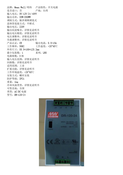
品牌:Mean Well/明纬产品特性:开关电源是否进口:否产地:台湾
输入电压:5V/12V/24/48VV
输出功率:35W-350WW
调制方式:脉冲调频调宽式
晶体管连接方式:半桥式
输出电压:220V
输出纹波噪音:详情见说明书
输出电压精度:详情见说明书
电压调整率:详情见说明书
负载调整率:详情见说明书
产品认证:CE 输出电流:0.5-15A 工作频率:50HZ 工作温度:-20~65℃外形尺寸:55.5*100*125.2mm
最小包装数:1 系列:LRS
电源相数:3相
输入电压范围:详情见说明书
回路数:详情见说明书
适用范围:工业
扩展功能:详情见说明书
工作环境温度:-20~65℃
安装方式:螺丝安装
防护等级:IP21
重量:1kg
冷却风扇类型:详情见说明书
可售卖地:全国
类型:AC/DC电源
型号:DR-120-24。
DFE系列微型电感型号DFE252012C说明书
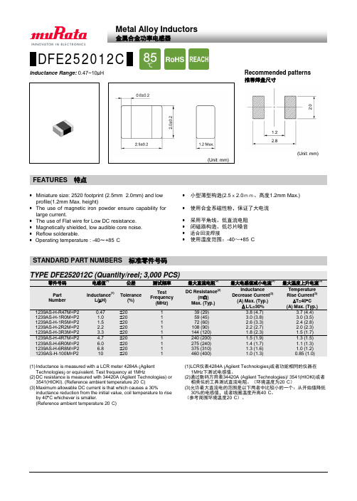
DFE252012C Inductance Range: 0.47~10µH(Unit: mm)(Unit: mm)•Miniature size: 2520 footprint (2.5mm×2.0mm) and lowprofile(1.2mm Max. height)•The use of magnetic iron powder ensure capability forlarge current.•The use of Flat wire for Low DC resistance.•Magnetically shielded, low audible core noise.•Reflow solderable.•Operating temperature : -40~+85°C•小型薄型构造(2.5x2.0mm、高度1.2mm Max.)•使用合金系磁性粉,保证了大电流•采用平角线、低直流电阻•闭磁路构造、低芯片噪音•适合回流焊接•使用温度范围:-40~+85°CTYPE DFE252012C (Quantity/reel; 3,000 PCS)零件号码电感值(1)公差测试频率最大直流电阻(2)最大电感值减小电流(3)最大温度上升电流(3)PartNumberInductance(1)L(µH)Tolerance(%)TestFrequency(MHz)DC Resistance(2)(mΩ)Max. (Typ.)InductanceDecrease Current(3)(A) Max. (Typ.)ΔL/L=30%TemperatureRise Current(3)∆T=40°C(A) Max. (Typ.)1239AS-H-R47M=P2 0.47 ±20 1 39 (29) 3.8 (4.7) 3.7 (4.4) 1239AS-H-1R0M=P2 1.0 ±20 1 59 (45) 3.0 (3.8) 3.0 (3.5) 1239AS-H-1R5M=P2 1.5 ±20 1 72 (60) 2.6 (3.3) 2.4 (2.8) 1239AS-H-2R2M=P2 2.2 ±20 1 108 (90) 2.2 (2.7) 2.0 (2.3) 1239AS-H-3R3M=P2 3.3 ±20 1 144 (120) 1.8 (2.3) 1.5 (1.7) 1239AS-H-4R7M=P2 4.7 ±20 1 240 (200) 1.5 (1.9) 1.3 (1.5) 1239AS-H-6R0M=P2 6.0 ±20 1 275 (240) 1.4 (1.7) 1.1 (1.3) 1239AS-H-6R8M=P2 6.8 ±20 1 375 (310) 1.3 (1.6) 1.0 (1.2) 1239AS-H-100M=P2 10 ±20 1 460 (400) 1.0 (1.3) 0.85 (1.0)(1) Inductance is measured with a LCR meter 4284A (AgilentTechnologies) or equivalent. Test frequency at 1MHz(2) DC resistance is measured with 34420A (Agilent Technologies) or3541(HIOKI). (Reference ambient temperature 20°C)(3) Maximum allowable DC current is that which causes a 30%inductance reduction from the initial value, coil temperature to riseby 40°C whichever is smaller.(Reference ambient temperature 20°C)(1)LCR仪表4284A (Agilent Technologies)或者功能相同的仪器在1MHz下测试电感值。
酷冷来袭 芯睿天王星I液冷套装
酷冷来袭芯睿天王星I液冷套装
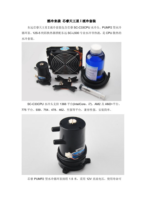
东远芯睿天王星I液冷套装包含芯睿SC-C33CPU水冷头、PUMP2型水冷循环泵、12S-5纯铝换热器搭配东远SC-L500专业水冷导热液,是CPU散热的水冷套装。
SC-C33CPU水冷头支持1366平台(IntelCore、i7)、AM2及AM2+平台、775平台、939、754、478、462、至强等平台,兼容性强,安装简单。
芯睿PUMP2型水冷循环泵扬程1.5米,采用12V直流电压,使用寿命可
达30000小时,能够提供更大的循环动力,专用测速线,更可靠泵体加装胶托,有效减震降噪。
东远12S-5换热器采用先进的纯铝制换热器,更强散热性能,符合欧洲环保要求,12L-T超大散热面积换热器,可轻松应对CPU的散热需求。
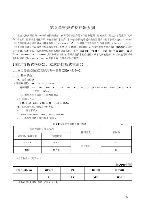
管壳式换热器的常用规格
159
1
1.60
—
—
—
219
1
2.50
—
—
—
273
L2
4.00
—
325
1
6.40
—
400
2
—
450
4
—
500
—
—
600
0.60
—
—
700
1.00
—
—
—
800
2.50
—
—
—
900
1
4.00
—
1000
2
—
—
(IWO)
—
—
—
1200
4
∙-
—
—
(1300)
0.25
0.60
Loo
1.60
2.50
—
—
—
150.8
202.1
—
4
542
27
0.0239
—
—
93.8
1423
190.9
—
6
518
24
0.0153
—
89.7
136.0
182.4
—
800
0-60
L 60
2.50
4.00
1
797
31
0.1408
一
138.0
209.3
280.7
—
2
776
31
0.0686
—
—
134.3
203.8
273.3
—
4
722
31
51
0.1838
DP2525B原边反馈电源芯片充电器应用方案

DP2525B原边反馈电源芯片充电器应用方案
DP2525是一款高精准的恒流/恒压原边反馈控制器集成800V功率三极管(BJT)。
待机功耗小于100mW(AC230V),适合应用在低成本高能效、高动态响应的小功率充电器和适配器以及LED领域。
集成了独有恒压(CV)和恒流(CC)控制技术,可实现小于±4%的恒压恒流精度。
在恒流(CC)控制电流和输出功率可以通过CS脚的电流采样电阻RS来调整,在恒压(CV)控制多模式控制操作可实现高可靠性高效率.负载全程无音频噪音。
独有的频率抖动技术,可以轻松提高EMI余量,降低EMI器件的成本。
优化动态响应,降低输出纹波。
DP2525B产品特点:
原边反馈,内置800V BJT无需光耦和TL431
全电压输入可达±4%的CC/CV高精度输出
全电压输入可达±4%的CC/CV高精度输出
内置软启动
可编程输出线压降补偿
内置变压器感量误差补偿
内置初级反馈的二次侧恒流控制
内置自适应电流峰值调整
多模式控制增强可靠性、提高效率
严格的CC调节可编程线路补偿
内置混合频率抖动改善EMI
内置平滑降频折返专利技术消除音频噪音
内置音频噪音抑制技术
内置同步斜率补偿
逐周期电流限制
内置高低压过功率OCP补偿
内置前沿消隐(Leading edge blanking)
VDD 欠压保护(UVLO)
VDD 过压保护及钳位
内置输出短路保护
典型应用图:
DP2525B原边反馈电源芯片充电器应用方案DP2525B广泛应用于:
电池充电器
适配器
机顶盒电源。
东远AT360换热器
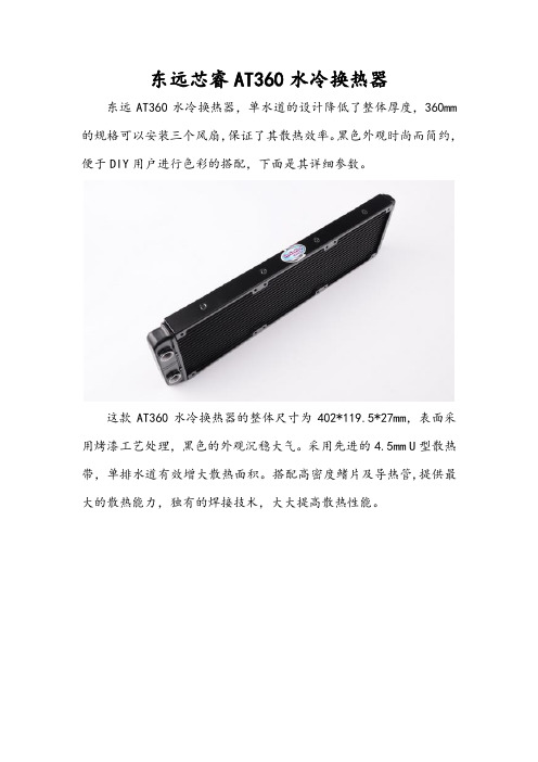
东远芯睿AT360水冷换热器东远AT360水冷换热器,单水道的设计降低了整体厚度,360mm 的规格可以安装三个风扇,保证了其散热效率。
黑色外观时尚而简约,便于DIY用户进行色彩的搭配,下面是其详细参数。
这款AT360水冷换热器的整体尺寸为402*119.5*27mm,表面采用烤漆工艺处理,黑色的外观沉稳大气。
采用先进的4.5mm U型散热带,单排水道有效增大散热面积。
搭配高密度鳍片及导热管,提供最大的散热能力,独有的焊接技术,大大提高散热性能。
东远芯睿AT360换热器最大的设计亮点要属它自带的内径8mm 的水嘴了。
不要小看这个小小的改进,因为它大大减少了安装的步骤,并且降低了由于安装不当可能带来的漏液的风险,保证使用水冷的安全。
与此同时,AT360换热器支持同时最多安装6个120风扇,适合于大功率的散热,可以根据具体工作的需要任意选择。
FX2N-4AD-PT在热熔胶机系统中的应用
在温度控制系统 中,I P D控 制 的应 用 很 普 遍 。 熔 胶 机 是 典 热 型 的 负 动 作 PD 控 制 对 象 , 理 地选 择 PD 参 数 可 以 取 得 很 好 I 合 I 的控 制 效 果 及 控 制 精 度 。
1 系 统 组 成
BM F 14 . 58 . 9 2 l 1.1 3{ 6 f 1-2 7 0 # 2 -2 l 7 #
c tol moo h on r , s t he t d a e ho mel dhe ie, u t p a ur i a u a en t e s o c r o iain Hih s se sa i yg e t t t a sv gl' em ert e s cc r t o a y t a b n t . g y t m t b l . r a l e z o i t y
数 字 范 围错 误 锁 存
热熔 胶 机 系 统 主要 包 括 熔 缸 上 部 加 热 器 、 部 加 热 器 、 频 下 变
器 与 齿 轮 泵 、 管 、 枪 及 控 制 器 。 其 中 有 四个 独 立 加 热 系 统 : 喉 胶
上 、 熔 缸 , 管 , 枪 。 制 部 分 采 用 了三 菱 F 3 3 M L 下 喉 胶 控 X U一 2 T P C 做 为 主 控 制 器 , 成 相 应 控 制 逻 辑 及 P D 运 算 等 操 作 , 了 精 准 完 I 为 控制 各个 环 节 的胶 温 , 用 了 P D 闭 环 控 制 , X N 4 D— T作 采 I F2 一 A P
3 MT P C d l a d e e a u e c mbn t n o a he e y t m i f u p r f t e PI ls d— o p t mp r t r 2 L mo ue n t mp rt r o iai t c i a s s e o v n o r a t o h D co e lo e e au e s
东殊半导体DS202线缆电子标签(PD E-Marked)芯片数据手册说明书
东殊半导体DS202线缆电子标签(PD E-Marked)芯片数据手册第4.0版Copy right © 2020 by DongShu Semiconductor(Shen Zhen) Co., Ltd., All rights reserved2022-10-10深圳龙华电话:136****2295网址:邮箱:**********************目录1.适用范围 (2)2.PD Emark功能简述 (2)3.典型电路 (3)4.电气特征 (4)5.工作范围 (4)6.PD Emarked数据 (5)7.关于认证 (5)1.适用范围根据USB IF,凡是USB3.0及以上线缆(USB3.1,USB3.2,USB4.0),或者是电源电流超过3A的USB2.0的线缆,均需要PD emark功能,那么具有PD Emark 功能的芯片DS202将能满足这方面的要求,当然你也可以使用东殊半导体的另一款DS201芯片,它的功能更为强大。
2.PD Emark功能简述根据USBIF的标准,PD Emark原理如下框图所示:其中Source指的是电源(比如手机充电器或笔记本电脑的电源),而Sink为需要电源的设备(比如手机或笔记本电脑),当Source给Sink供电时,需要通过PD线缆,而这根线缆两端都是TYPE-C结构,因为只有TYPE-C才有CC1和CC2两根连线,具体Source和Sink将利用CC1和CC2中的一根相互进行通讯(图中CC线),另一根线会对线缆中PD Emark功能模块进行供电(图中Vconn 线);Source会根据Sink的请求提供不同的电压,以及对电流进行限流控制,根据最新的PD协议,最高电压可以达到48V,最大电流可以达到5A。
但是不是所有的线缆能够承受最高48V的电压或最大5A的电流,这就是嵌在线缆中PD Emark芯片存在的意义,PD Emark芯片会告诉Source或Sink线缆的基本情况:可承受的最高电压和最大电流,以及线缆长度,制造商等其它信息。
一种LED灯散热器、该散热器的制作方法及LED灯[发明专利]
![一种LED灯散热器、该散热器的制作方法及LED灯[发明专利]](https://img.taocdn.com/s3/m/3d8bf9dbaff8941ea76e58fafab069dc502247fe.png)
专利名称:一种LED灯散热器、该散热器的制作方法及LED灯专利类型:发明专利
发明人:郁新新,陈成,沈达,牛绪儒,杨永胜,杨念,王浩,李兰馨,胡洪义,陈砚欣,王永
申请号:CN202210179510.4
申请日:20220225
公开号:CN114551702A
公开日:
20220527
专利内容由知识产权出版社提供
摘要:一种LED灯散热器,包括顶层的周期性微结构、中间的薄膜层和底部的基底层,在周期性微结构之间设置有若干用于空气热对流进行散热的沟槽。
本申请具有体积小、重量小、散热性能高、可高达集成、通用性好的优点,不仅可以集成在大部分通用的LED芯片驱动电路基板上,而且利用压印模板可以实现产品的快速批量化生产,并且在8‑14微米的大气窗口具有高热辐射率。
申请人:连云港杰瑞电子有限公司
地址:222000 江苏省连云港市海州区圣湖路18号
国籍:CN
代理机构:连云港润知专利代理事务所
代理人:马强
更多信息请下载全文后查看。
90Sr同位素电池放射源的设计模拟与辐射优化
收 稿 日 期 $%$!G%:G%&修 回 日 期 $%$!G%;G$# 基 金 项 目 甘 肃 省 科 技 重 大 专 项 计 划 资 助 项 目 6(5$$Mc9NK%$%
:%
同 位 素!!第!"卷
!!;%I*同位素温差热电 池 是 利 用;%I*衰 变 热" 将辐射能转化为电能的同位素电池 & *#+ 电 池 的 放 射 性 热 源 来 自 于 高 放 废 液 的 提 取"这 种 清 洁 能 源 技 术 有 效 利 用 了 核 废 料 的 能 源 潜 力"将 放 射 性 废 液 中 衰 变 能 转 化 为 电 能 "并 在 极 地 %深 海 等 无 法 传 输 传 统 能 源 的 场 合"提 供 可 靠 的 电 力 保障&
第!"卷 第#期
! $%$&年$月
同!位!素
'()*+,-(./0(1(230
4(-5!"!6(5# 7385$%$&
ANC)同位素电池放射源的设计模拟与辐射优化
杨立群贾楠楠周!剑李叶凡唐!军
中 核 四 + 四 有 限 公 司 兰 州 !"!$C:%
摘要;%I*具有较强的轫致辐射在制备 同 位 素 放 射 源 前需 要 先 模 拟;%I*DLU! 陶 瓷 芯 块 的 组 分设 计 热 源盒的结构并根据制造工艺对芯 块热 源 包 壳 进 行 轫 致 辐 射 评 估 为 了 减 少 热 电 转 换 器 件 的 受 照 剂 量本研究根据$射线的屏蔽原理提出使用铝箔 包 裹 芯 块优 化 芯 块 配 料 和 增 加 氮 化 硼 垫 片 的 三 种 降 低放射源轫致辐射的方法ZQ6X 模拟结果显示三 种 方 法 都 能 有 效 降 低 轫 致 辐 射 三 种 方 法 均 会 改 变热源盒设计尺寸且包裹铝箔的方法工程可行性较差以上结果可为;%I*温差热电池热源部分的设 计 与 制 造 提 供 参 考 并 为 电 池 的 辐 射 优 化 提 供 理 论 方 法 关 键 词 同 位 素 放 射 源 ZQ6X轫 致 辐 射 ;%I*DLU! 热 源 包 壳 中图分类号DE"DE;$;!! 文献标志码F!!文章编号#%%%G":#$$%$&%#G%%&;G%9 !"##%5":!C1H05$%$!5^()YL,+5%$"
XW Power System安装指南附录(XW序列混合逆变充电器120V 240V分相模型转换为1
This addendum is for the XW Power System Installation Guide (Document Part Number 975-0239-01-01, Revision C). It provides additions to the manual related to converting an XW Series Hybrid Inverter/Charger 120V/240V split-phase model to a 120V single-phase, setting up an XW 120V single-phase system, and setting up an XW 120V three-phase system. This addendum only applies to the XW6048-120/240-60 120-60 inverter/charger model – Product Part Number 865-1000-01.The additions are:•A new subsection under System Components and Accessories.•A new table Grid-tie Specifications under Electrial Specifications in Appendix A.• A new Appendix, XW Series Hybrid Inverter/Charger 120V/240V Split-Phase to 120V Single-Phase Conversion Instructions .Additional information on the XW Series Hybrid Inverter/Charger can be found in the XW Hybrid Inverter/Charger Operation Guide (Document Part Number 975-0240-01-01).System Components and AccessoriesOn page 1-3 of the XW Power System Installation Guide, add the following subsection to System Components and Accessories :XW Jumpers (XW6048-120/240-60 120-60 Model Only)The jumpers are used to reconfigure a standard XW 120/240V , 3-wire model to accept 120V , 2-wire connection. Use the jumpers to reconfigure the transformer wires. For instructions, see Appendix D, XW Series Hybrid Inverter/Charger 120V/240V Split-Phase to 120V Single-Phase Conversion Instructions .Addendum to the XW PowerSystem Installation Guide Addendum XW6048-120/240-60120-60976-0222-01-01 Rev. BXW6048-120/240-60 120-602976-0222-01-01Electrical SpecificationsOn page A-2 of the XW Power System Installation Guide, add the followingtable:Table 1Grid-tie Specifications 120/240 Va a.Models XW6048-120/240-60, XW4548-120/240-60, and XW4024-120/240-60.120 V b b.Model XW6048-120/240-60 120-60 only.Response Time Anti-islanding reconnect254.4 V 127.2 V 300 s Over frequency disconnect60.5 Hz 60.5 Hz 100 ms Under frequency disconnect59.3 Hz 59.3 V 100 ms Over voltage LN fast disconnect135 V 135 V 60 ms Over voltage LN slow disconnect132 V 132 V 500 ms Over voltage L1/L2 fast disconnect270 V –100 ms Over voltage L1/L2 slow disconnect264 V –500 ms Under voltage LN fast disconnect75 V 75 V 100 ms Under voltage LN slow disconnect105.6 V 105.6 V 1000 ms Under voltage L1/L2 slow disconnect211.2 V –100 ms Under voltage L1/L2 fast disconnect 150 V –100 msAddendum New AppendixAdd the following appendix after Appendix C in the XW Power SystemInstallation Guide:Appendix D XW Series Hybrid Inverter/Charger 120V/240V Split-Phase to 120V Single-Phase Conversion InstructionsConverting from 120/240V split-phase to 120V single-phase is required insystems with single-phase (2-wire 120V) or three-phase (208/120V) sources (suchas generators or grid). For a three-phase system, the loads may consist of single-phase loads or three-phase loads. Please refer to the wiring diagrams starting onpage13. If you have questions, contact Xantrex customer service at*******************************************.Important:To complete the conversion, you must refer to instructions in the XWConfig User’s Guide (Document Part Number 975-0365-01-01). If you want to set up asingle-phase system, you must refer to instructions in the XW Series Hybrid Inverter/Charger Operation Guide (Document Part Number 975-0240-01-01). If you do not havethese guides, download them from .This Appendix is divided into the following sections:•“Converting 120V/240V Split-Phase to 120V Single-Phase” on page 4•“Parts and Tools Required” on page 4•“Disconnecting Power Sources” on page 4•“Removing the Wiring Compartment Cover” on page 5•“Reconfiguring the Secondary Transformer Wires on X1 and X2Connectors” on page 6•“Reconfiguring the AC Ports on the Load, AC1, and AC2 Connectors” onpage 8•“Upgrading the Firmware” on page 8•“Setting Up a Single-Phase System” on page 10•“Setting Up a Three-Phase System” on page 10•“XW 120V Balanced Three-phase System with Renewable Energy (Solar) –Customer-supplied AC Breakers” on page 13•“XW 120V Balanced Three-phase System with Renewable Energy (Solar) –Xantrex-supplied AC Breakers” on page 14•“XW 120V Single-phase System with Renewable Energy (Solar) – Xantrex-supplied AC Breakers” on page 15976-0222-01-013XW6048-120/240-60 120-604976-0222-01-01Converting 120V/240V Split-Phase to 120V Single-PhaseThe following sections provide instructions on how to reconfigure a standard XW120/240V , 3-wire model to accept 120V , 2-wire connection. To set up a three-phase system using three XW 120V configured XW units, perform these steps forall three inverter/chargers.Parts and Tools RequiredTo complete the conversion, you will need one small jumper and three largejumpers as shown in Figure 1. These jumpers are included in the packaging bagshipped with each XW inverter/charger.You will need a Phillips #2 screwdriver and may require other tools, as necessary.Disconnecting Power SourcesTo disconnect power sources:1.Put the XW system in Standby mode using the System Settings menu on theXW System Control Panel, but do not disconnect DC sources (for example,batteries). Do not turn off the DC breaker.2.Disconnect AC sources (such as the utility grid and generators) by turning offthe AC input breakers.3.Turn off and disconnect all AC loads by turning off the AC output breaker.Figure 1JumpersNote:It is not necessary to remove the unit from its mounting position to perform the following tasks.Addendum976-0222-01-015Removing the Wiring Compartment CoverTo remove the wiring compartment cover:1.Remove Screw A and B shown in Figure2.2.Remove the wiring compartment cover (see Figure 3 on page 6).Figure 2XW Inverter/Charger Front View Screw AWiringCompartmentCoverScrew BXW6048-120/240-60 120-60Reconfiguring the Secondary Transformer Wires on X1 and X2 ConnectorsTo reconfigure the secondary transformer wires on the X1 and X2connectors:1.Locate the X1 and X2 connectors (see Figure 3).X1 and X2 ConnectorsTorque InformationLoad, AC1 (Grid), andAC2 (Gen) ConnectorsFigure 3Connector Locations.2.Remove the secondary transformer wire X2 (black) from slot X2-A, and theninsert it into slot X2-B (see Figure 4 and Figure 5).3.Remove the secondary transformer wire X3 (white) from slot X3-A, and theninsert it into slot X3-B (see Figure 4 and Figure 5).4.Insert one small jumper between slot X2-A and X2-B (see Figure 4 andFigure 5). The jumper must be on top of the wire.5.Tighten all terminals to 35 in-lb per the torque information printed on the ACboard. See Figure 3 for the torque information location.6.Make sure the new connections are correct by comparing them to the afterphotograph displayed on the right in Figure 5.6976-0222-01-01Addendum976-0222-01-017Figure 4Slot Locations on X1 and X2 ConnectorsFigure 5X1 and X2 Connectors Before and After ReconfigurationSlot X2-ASlot X2-BSlot X3-BSlot X3-ASecondary transformer wire X1, X2, X3, andX4 locations BEFORE reconfiguration X1X2X3X4Slot X2-A, X2-B, X3-A, and X3-B locations on X1 and X2 connectors AFTER reconfiguration X1X2X3X4JumperXW6048-120/240-60 120-608976-0222-01-01Reconfiguring the AC Ports on the Load, AC1, and AC2 ConnectorsTo reconfigure the AC ports on the Load, AC1 (Grid), and AC2 (Gen)connectors:1.Locate the Load, AC1 (Grid), and AC2 (Gen) connectors (see Figure 3 onpage 6).2.Insert one large jumper in each connector to short out N and L2, as shown inFigure 6.3.Connect the AC cables as shown in Figure 6.4.Tighten all terminals per the torque information printed on the AC board. SeeFigure 3 on page 6 for the torque information location.Upgrading the FirmwareTo upgrade the firmware, you must refer to instructions in the XW Config User’s Guide (Document Part Number 975-0365-01-01). If you do not have this guide,download it from .To upgrade the firmware:1.Acquire the USB-to-Xanbus™ adapter to connect the XW System to a PC(Product Part Number 865-1155).2.Download the USB-to-Xanbus adapter driver (available on).3.Connect the USB-to-Xanbus adapter to a USB port on your computer, andthen install the downloaded driver. See the XW Config User’s Guide fordetailed instructions.4.Download and save the latest XW6048-120V firmware onto your computer(available on the XW product page at ).Figure 6Jumper Locations and AC Cable Configuration on AC PortsLoad AC1 (Grid)AC2 (Gen)Addendum976-0222-01-0195.Make sure nominal DC voltage is present at the unit’s DC terminals.6.Download and install the latest XWConfigPro to your computer (available onthe XW product page at ).7.Run XWConfigPro.8.Select Convert from the XWConfigPro menu (see Figure 7), and then followthe on-screen instruction to complete the conversion.9.For future reference, record the new firmware version.The conversion of one XW 120V/240V split-phase model to a 120V single-phase model is now complete.•To set up a single-phase system, repeat the steps in “Converting 120V/240V Split-Phase to 120V Single-Phase” starting on page 4 for up tothree more inverter/chargers, and then continue to “Setting Up a Single-Phase System” on page 10.•To set up a three-phase system using three XW 120V single-phasemodels, repeat the steps in “Converting 120V/240V Split-Phase to 120V Single-Phase” starting on page 4 for two more inverter/chargers, and then continue to “Setting Up a Three-Phase System” on page 10.Figure 7XWConfigProXW6048-120/240-60 120-60Setting Up a Single-Phase SystemBefore setting up a single-phase system, perform the steps in “Converting 120V/240V Split-Phase to 120V Single-Phase” starting on page 4 to convert up to fourXW 120V/240V split-phase models to 120V single-phase models.A maximum of four inverters can be installed in parallel for a single-phasesystem.Important:In a four-inverter system, a second XW PDP is required.The XW Series Hybrid Inverter/Charger Operation Guide (Document PartNumber 975-0240-01-01) contains instructions for setting up a single-phasesystem. After converting split-phase models to single-phase models, follow theconfiguration instructions in the guide to set up a single-phase system.Setting Up a Three-Phase SystemBefore setting up a three-phase system, perform the steps in “Converting 120V/240V Split-Phase to 120V Single-Phase” starting on page 4 to convert three XW120V/240V split-phase models to 120V single-phase models.To set up a three-phase system:1.Daisy chain XW-phA, XW-phB, and XW-phC at each unit’s AC sync port. Todo this, connect an AC sync cable between unit 1 and unit 2. Next, connect anAC sync cable between the second AC sync port in unit 2 and an AC syncport in unit 3. Network terminators are not required for AC Sync connections.2.On the System Control Panel (SCP), select XW6048 00 > Advanced Settings> Multiunit Config.3.Change the device name or device number in the proper sequence.4.Under Invtr Mode, select:•3Ph L1Master for unit 1 or Phase A•3Ph L2Master for unit 2 or Phase B•3Ph L3Master for unit 3 or Phase C5.Optionally, up to one additional unit may be installed in parallel on eachphase. This allows for a maximum of 6 XW units in a three-phase system. Thesecond unit on each phase (parallel) must be configured as 3PhL1Slave,3PhL2Slave, and 3PhL3Slave respectively. A maximum of two units perphase is allowed.Important:In a six-inverter system, a second XW Power Distribution Panel isrequired.10976-0222-01-01Addendum976-0222-01-01116.Make sure the Grid or Gen wiring has the correct A, B, C phase sequence withthe three XW inverter/chargers. If the phase sequence is incorrect, the XWsystem will not qualify the input AC voltage.7.Put the wiring compartment cover back in place, and then power up theconverted units. Perform an AC voltage measurement in invert mode. Makesure the output voltage is within 115 – 120 Vac.When installed in a three-phase system, the XW inverter/charger checks for theexistence of a master on each phase. If there is not a master unit on each phase, asystem-wide fault (F66) is asserted. Each XW inverter/charger has to beassociated with a phase or line. To associate an XW inverter/charger with a phaseor line, select one of six available three-phase inverter modes shown in Table 2.it does not exceed 30kW. The power adjustment on each phase must be made at time of commissioning and under supervision of a utility representative.Table 2Three-phase Inverter Modes Line or Phase Inverter Mode Role Assignment a a.Each phase can support one master unit and one slave unit.Suggested Device Number Line-1 or Phase-A3Ph L1 Master b b.The L1 Master is also the master inverter/charger for the entire system. The sys-tem master broadcasts phase synchronizing pulses through its sync port, and eachphase master controls the other units on its respective phase.Phase-A or Line-1 Master 103Ph L1 Slave c c.The second unit in each phase is optional.Phase-A or Line-1 Slave 11Line-2 or Phase-B3Ph L2 Master Phase-B or Line-2 Master 203Ph L2 Slave Phase-B or Line-2 Slave 21Line-3 or Phase-C 3Ph L3 MasterPhase-C or Line-3 Master 303Ph L3 Slave Phase-C or Line-3 Slave 31Note:Device numbers are only suggested to facilitate identifying devices on the systemas well as phase association from a device’s name and number. Customize the naming asdesired. Conflicting device names are allowed and will not cause faults in the system.XW6048-120/240-60 120-6012976-0222-01-01Trademarks Xantrex , Xanbus , and Smart choice for power are trademarks of Schneider Electric, registered in the U.S. and other countries. Other trademarks, registered trademarks, and product names are the property of their respective owners and are used herein for identification purposes only.Notice of Copyright Copyright © 2009 Xantrex Technology Inc. No part of this document may be reproduced in any form or disclosed to third parties without the express written consent of:Xantrex Technology Inc.161-G South Vasco Road Livermore, California USA 94551Xantrex Technology Inc. reserves the right to revise this document and to periodically make changes to the content hereof without obligation or organization of such revisions or changes unless required to do so by prior arrangement. All warranty, disclaimer and safety information is contained within the primary documentation received with your unit. Please ensure you are familiar with that information before proceeding.Date and RevisionJuly 2009 Rev. B Part Number 976-0222-01-01Contact InformationTelephone:650 351 8237 (direct)186****1470(tollfreeNorthAmerica)Fax:1 604 422 2756 (direct)Email:***************************Web: Addendum XW 120V Balanced Three-phase System with Renewable Energy (Solar) – Customer-supplied AC BreakersFigure 8XW 120V Balanced Three-phase System with Renewable Energy (Solar) – Customer-supplied BreakersAddendumXW 120V Balanced Three-phase System with Renewable Energy (Solar) – Xantrex-supplied AC BreakersFigure 9XW 120V Balanced Three-phase System with Renewable Energy (Solar) – Xantrex-supplied BreakersAddendum XW 120V Single-phase System with Renewable Energy (Solar) – Xantrex-supplied AC BreakersFigure 10XW 120V Single-phase System with Renewable Energy (Solar) – Xantrex-supplied AC BreakersAddendum。
- 1、下载文档前请自行甄别文档内容的完整性,平台不提供额外的编辑、内容补充、找答案等附加服务。
- 2、"仅部分预览"的文档,不可在线预览部分如存在完整性等问题,可反馈申请退款(可完整预览的文档不适用该条件!)。
- 3、如文档侵犯您的权益,请联系客服反馈,我们会尽快为您处理(人工客服工作时间:9:00-18:30)。
东远芯睿PD240水冷换热器
换热器刚开始采用的铜材质,而由于造价重量等因素现在大部分都换成了铝。
但是东远PD240水冷换热器仍然采用了铜材质。
下面是它的详细参数。
这款东远芯睿PD240换热器的尺寸为269*120*45mm,这样的厚度配上铜本身的导热效果,保证其既有足够的热量容纳能力,又可以将热量及时散去,吸热与散热完美结合。
表面采用质感喷漆处理,黑色的外观高贵沉稳。
先进的6mm U型散热带,有效增大了单排水道的散热面积,再加上独有的焊接技术,大大提高了散热性能。
双排水道设计,容热能力更强,纯铜材质也同样为导热能力加分。
至于接头方式,这款换热器采用了G1/4螺纹,可以根据自身需要选择内径为6、8或者10mm的水嘴。
正反两面最多可以安装四个120mm规格的风扇,散热效果更强劲,可满足大功率散热。