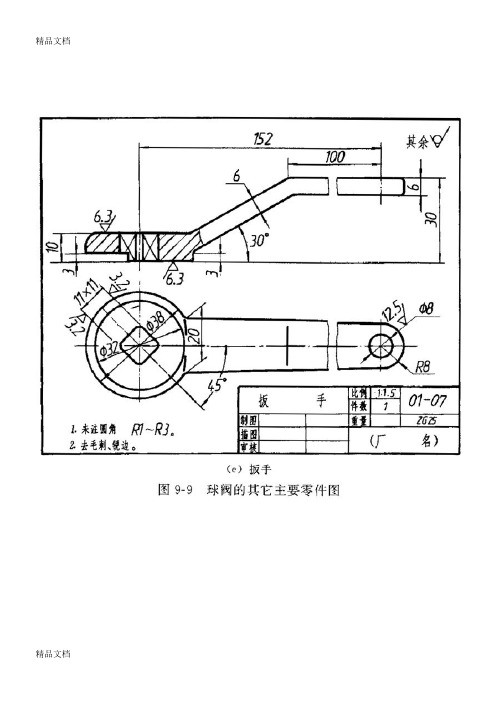
mogas 球阀样本
(整理)球阀装配图
(3)介绍评价对象的选址、总图布置、水文情况、地质条件、工业园区规划、生产规模、工艺流程、功能分布、主要设施、设备、装置、主要原材料、产品(中间产品)、经济技术指标、公用工程及辅助设施、人流、物流等概况。
(2)评价范围。根据评价机构专业特长和工作能力,确定其相应的评价范围。
3.不同等级的环境影响评价要求[例题-2005年真题]《中华人民共和国环境影响评价法》规定,建设项目可能造成轻度环境影响的,应当编制( )。
3)应用污染物排放标准时,依据项目所属行业、环境功能区、放的污染物种类和环境影响评价文件的批准时间确定采用何种标准。综合性排放标准与行业性排放标准不交叉执行,即:有行业排放标准的执行行业排放标准,没有行业排放标准的执行综合排放标准。
球阀样本(最新)

代号连接方式 内螺纹 外螺纹 法兰 承插焊 对焊 对夹 卡箍卡套NWFH SH BCKT6.连接型式代号注:密封副中两密封面材料不同时,用低硬度材料代号代号铬及铬锰系合金钢硬质合金 铜合金 渗氮钢蒙乃尔合金锡基轴承(巴氏)合金聚四氟乙烯密封面或衬里材料H Y T D M B F橡胶尼龙塑料衬胶衬铅衬搪瓷衬聚全氟乙丙烯衬聚三氟乙烯X N J Q C F46 F3代号密封面或衬里材料8. 密封副材料代号1.01.62.54.06.410.016.032.0101625406410016032015030040060080090015002500A1A3A4A6A8A9A15A251020456511014018010K 20K 45K 65K 110K 140K 180K15030040060080090015002500150Lb 300Lb 400Lb 600Lb 800Lb 900Lb 1500Lb 2500Lb16254064100162540641001625406410016025040016254064100160250400国家标准 美国标准 日本标准 英国标准 法国标准 德国标准MPa 代号 CLASS 代号 K 代号 CLASS 代号 Bar 代号 Bar 代号9.压力等级代号例如:国标阀门 - DN100; 美标阀门 4”;缩径阀门 DN100×80(公称×缩径);4” ×3”。
(公称×缩径)11.口径:为阀门的公称通径5.角行程气动执行机构代号气动方式代号双作用6H单作用(带复位弹簧)6T两段开两段关6P一段开两段关6V双作用6单作用(带复位弹簧)6K 带手轮传动装置6※W气开 气关6B注:执行机构按用户要求配置手动装置时,在后面加“W”代号结构形式1245768930PY形L形 T形三通式直通式浮动球四通式直通式三通式固定球摆动球直通直通(偏心)T L 半球(V型)7.结构形式代号轨道式M Co C 3C 4Z KQHTi代号C(PN16以上省略)I C 6C 9V P P 8P 1P 3R R 8R 1R 3代号碳钢ZG1Cr5Mo、C5WC6WC9铬钼钒钢铬镍钛钢超低碳铬镍钛钢铬镍钼钛钢超低碳铬镍钼钛钢钛钢蒙耐尔合金LCB LC3LC4灰铸铁可锻铸铁球墨铸铁Cr13系不锈钢铬钼钢低温钢主体材料主体材料10.阀门主体材料代号25、WCB、WCC ZG12Cr1MoV ZG15Cr2Mo1V ZG1G18Ni9Ti CF8、304ZG0G18Ni9TiCF3、304L ZG1G18Ni12Mo2TiCF8M 、316ZG0G18Ni12Mo2FiCF3M 、316LTi HT KTQT Cr13 0506球阀阀门型号及图号的编制方法球阀阀门型号及图号的编制方法1-阀体2-螺柱7-阀杆8-键13-螺钉14-O型圈18-O型圈19-阀座24-阀盖25-下轴对于用户有防火要求的球阀,均设有防火结构。
MOGAS工厂介绍

在全世界,MOGAS是最典型、最专业的全金属密封球阀制造商之一,唯一的生产基地在美国德克萨斯的休斯顿。
自1973年起,MOGAS就持续提供高性能的球阀(适用于高温高压、高固体含量的介质,耐磨损、耐腐蚀)给众多的用户,包括电厂、石化、炼油及采矿行业。
是美国电厂阀门的首选,在电力行业市场占有率达80%以上。
2007年MOGAS工业公司并购美国RCC控制阀门公司(全称:美国理查德控制阀门有限公司,英文全称: RICHARD CONTROLS VALVES,INC.)后,综合RCC多年来在高压截止阀领域的成功经验和设计优势,融合MOGAS 的部分先进理念和工艺,在严格的质量管理、高效优质的服务的基础上推出MOGAS-RCC系列截止阀产品,并已在美国多家电力、石化行业用户得以成功应用。
原RCC品牌截止阀有着35年的设计、生产、服务经验,在欧美等地相关行业有着大量业绩和市场份额,在进入MOGAS 工业公司后,截止阀产品的质量、性能有了进一步提升,并已取得多家用户的首肯和赞赏。
MOGAS-RCC系列截止阀,适用于电力、石化行业各类绝对苛刻的工况。
MOGAS提供阀门问题的解决方案,让您选择最适合各类严酷工况的设计、阀内组件、材质和涂层。
MOGAS阀门分为RSVP系列、C系列、PORV系列球阀,质量保证期分别为4年、2年、2年,适用范围广泛,规格型号齐全。
RSVP系列在电厂的适用范围:锅炉疏水、汽机疏水、锅炉定排,连排、给水系统疏水、过热器排放及疏水、吹灰器隔离、旁路管线隔离。
C系列在电厂的适用范围:控制阀前后隔离、主蒸汽隔离、给水加热器隔离、锅炉给水泵隔离、通径3"以上管道隔离PORV系列在电厂的适用范围:PCV、锅炉压力释放、过热器压力释放MOGAS-RSVP系列疏水球阀特点:1、锻造阀体保证了可靠耐压能力。
2、球体和阀座都通过“渗透工艺硬化表层”的专利技术处理,并匹配研磨,100%密合确保绝对密封。
3、改良的ASVR系列阀门采用一体化支架法兰设计,提供执行机构的稳定安装,确保在支架和阀体之间无松动或偏移。
美国穆格型号
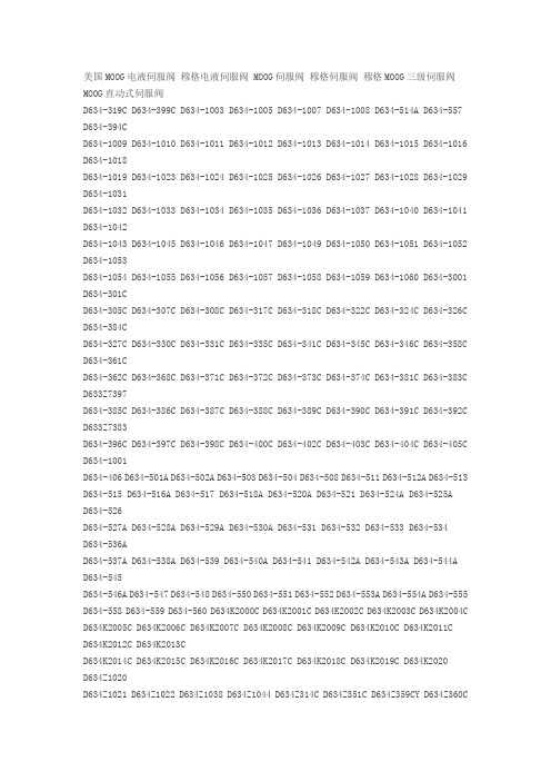
美国MOOG电液伺服阀穆格电液伺服阀 MOOG伺服阀穆格伺服阀穆格MOOG三级伺服阀MOOG直动式伺服阀D634-319C D634-399C D634-1003 D634-1005 D634-1007 D634-1008 D634-514A D634-557 D634-394CD634-1009 D634-1010 D634-1011 D634-1012 D634-1013 D634-1014 D634-1015 D634-1016 D634-1018D634-1019 D634-1023 D634-1024 D634-1025 D634-1026 D634-1027 D634-1028 D634-1029 D634-1031D634-1032 D634-1033 D634-1034 D634-1035 D634-1036 D634-1037 D634-1040 D634-1041 D634-1042D634-1043 D634-1045 D634-1046 D634-1047 D634-1049 D634-1050 D634-1051 D634-1052 D634-1053D634-1054 D634-1055 D634-1056 D634-1057 D634-1058 D634-1059 D634-1060 D634-3001 D634-301CD634-305C D634-307C D634-308C D634-317C D634-318C D634-322C D634-324C D634-326C D634-384CD634-327C D634-330C D634-331C D634-335C D634-341C D634-345C D634-346C D634-358C D634-361CD634-362C D634-368C D634-371C D634-372C D634-373C D634-374C D634-381C D634-383C D633Z7397D634-385C D634-386C D634-387C D634-388C D634-389C D634-390C D634-391C D634-392C D633Z7383D634-396C D634-397C D634-398C D634-400C D634-402C D634-403C D634-404C D634-405C D634-1001D634-406 D634-501A D634-502A D634-503 D634-504 D634-508 D634-511 D634-512A D634-513 D634-515 D634-516A D634-517 D634-518A D634-520A D634-521 D634-524A D634-525AD634-526D634-527A D634-528A D634-529A D634-530A D634-531 D634-532 D634-533 D634-534D634-536AD634-537A D634-538A D634-539 D634-540A D634-541 D634-542A D634-543A D634-544AD634-545D634-546A D634-547 D634-548 D634-550 D634-551 D634-552 D634-553A D634-554A D634-555 D634-558 D634-559 D634-560 D634K2000C D634K2001C D634K2002C D634K2003C D634K2004C D634K2005C D634K2006C D634K2007C D634K2008C D634K2009C D634K2010C D634K2011CD634K2012C D634K2013CD634K2014C D634K2015C D634K2016C D634K2017C D634K2018C D634K2019C D634K2020D634Z1020D634Z1021 D634Z1022 D634Z1038 D634Z1044 D634Z314C D634Z351C D634Z359CY D634Z360CD634Z360CYD634Z380C D634Z395C D634Z505A D634Z509 D634Z510 D634Z549A D633E703 D633E704D633E713AD633E714A D633E7365 D633E7366 D633E7411 D633K2000B D633K2001B D633K2002BD633K2003BD633K2005B D633K2006B D633K2007B D633K2008B D633K2009B D633K2010B D633K2011BD633K2012BD633K2013B D633K2014B D633K2015B D633K2017B D633K2018B D633K2019B D633K2020BD633K2021BD633K2022B D633K2023B D633K2024B D633K2025B D633K2026B D633K2027B D633K2028BD633K2029BD633K2030B D633K2031B D633K2032B D633K2033B D633K2034B D633K2035B D633K2036BD633K2037BD633K2038B D633K2039B D633K2040B D633K2041B D633K2042B D633K2043B D633K2044BD633K2045BD633K2046B D633K2047B D633K2048B D633K2049 D633K2050 D633K2051 D633Z303B D633Z305B D633Z313BD633Z317B D633Z338B D633Z348B D633Z371B D633Z379B D633Z480B D633Z506B D633Z528B D633Z529BD633Z532B D633Z539B D633Z557B D633Z570B D633Z585B D633Z586B D633Z587B D633Z588B D633Z589BD633Z590B D633Z7309 D633Z7324 D633Z7337 D633Z7352 D633Z7353 D633Z7361 B67728-001 B67728-002B67728-003 A03665-060美国Moog伺服阀说明:美国Moog伺服阀MOOG穆格伺服阀D633,D634系列,G761-3005,G761-3004,G761-3003,G761-3002,G761-3001,J761,J072,J869,G631 G761系列伺服阀 D791三级伺服阀 D661电反馈式伺服 72系列机械反馈伺服 D633/D634直动式伺服阀功率级阀型号/先导级 MOOG机能代号 D661-4651/ C41156-421 G35JOAA6VSX2HA D661-4652/ C4 1156-421 G15JOAA6VSX2HA D661-4636/C41156-421 G60KOAA5VSX2HA D661-4469C/C41156-421 G75KOAA6VS X2HA D661-4697C/C41156-421 G15JOAA5VSX2HA D661-4033/ C41156-421 P80HAAF6VSX2-A D661-4059/C41 156-411 P80HAAF6VSX2-B D661-4444C/C41156-421 G60JOAA6VSX2HA D661-4443C/C41156-421 G45J0AA6VS X2HA D661-4506C/C41156-421 G23J0AA6VSX2HA D661-4539C/C41156-421 G35JOAA5VSX2HA MOOG型号/先导级 MOOG机能代号 D662Z4311K/D630-072A P01JXMF6VSX2-A D662-4010/D061-8411 D02HABF6VSX2-A D662Z 4336K/D630-272D P01JXMF6VSX2-A MOOG型号/先导级 MOOG机能代号 D663Z4307K/D630Z067A P02JONF6VS X2-A D663-4007/D061-8412 L03HABD6VSX2-A MOOG型号/先导级 MOOG机能代号 D663Z4307K/D630Z067A P 02JONF6VSX2-A D663-4007/D061-8412 L03HABD6VSX2-A D634-341C R40K02M0NSS2 D634-319C R40KO2M0NS P2 D633-333B R16KO1F0NSS MOOG型号/先导级 MOOG机能代号 D791-5009/D761-2612 S16J0QA6VSB0-P D7 91-4025/ S25J0PA6VSX2-A D791-4001/待查 S25J0QB6VSX2-B D791-4002/D761-2617 S25J0QB5VSX2-B D791-4028/D761-2619 S25J0QB6VSX2-B D791-4046/D761-2619 S25J0QA6VSX2-B MOOG型号 MOOG机能代号 07 2-559A S15F0FA4VBL, 072-558A S22FOFA4VBL《新型号:072-1203-10》。
佛尼斯锻钢阀样本

典型材料表 Main parts materials list
序号 No
1
零件名称 Part name
阀体Body
A105
材料Materials A350-LF2 A182-F5 A182-F11 A182-F22 A182-304 A182-304L A182-316 A182-316L
2
阀座Seat ring
5 润滑垫圈Washer
A276-410
6 手轮Handwheel
A197,A47
7 名牌Nameplate
8
锁紧螺母 H.W.Lock nut
9
螺纹Thread
铝Aluminum A108-1020 A276-410
10
阀杆Stem
A276-410
A276-304 A276-304L A276-316 A276-316L F51
特征和应用规范
1. 设计制造:API602,ANSI B16.34,BS5352,GB/T12224,GB/T12228,GB/T12234 2. 承插焊端:ANSI B16.11,JB/T175-95 3. 螺纹端:ANSI B1.20.1(NPT),GB/T7306-87(RC) 4. 对焊端:ANSI B16.25,GB/T12224 5. 法兰端:ANSI B16.5,JB/T82.1~82.4-94 6. 法兰阀门结构长度:ANSI B16.10,JB/T97-95 7. 结构特征:螺栓连接或焊接阀盖,明杆支架 8. 阀门的检验和试验:API598,GB/T13927,JB/T9092 9. 主体材质:A105,LF2,F5,F11,F22,F304,F316,F304L,F316L,F347,F321,F91,Monel,Alloy20
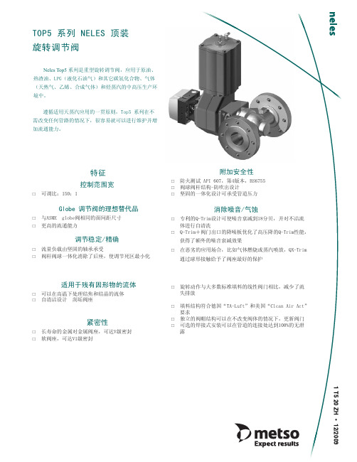
美卓顶装式球阀
⢋䓝⤥䐫
㾕义㸼
䔏⫔㋋䁚㑇ᷛ 㾕˂义㸼 䔏⫔⮘ㅻ䁚㑇ᷛ 㾕义㸼
嘽〚䇓㘇Ⳉ䔚䊻㋹䐧䇇䇤 ⭥䔏⫔䊫㿎Ი3
䇱㒘㑠㲹㾵
NiBO/⍖ሖ Cr/⍖ሖ Ⳍᇍ㸠
䕃䕈༫
䋌䅕㼜㘑㤛㼀
ᐌ㾘⧗䯔ా䷇
⊼ᛣ˖ҹϞؐഛЎ㒃⌕ԧˈᇍѢ⇨㱔ˈᴖ䋼ా䷇ⱘᑨ⫼എড়ˈ 䇋Ꮉॖ䆶᳔Ƹ3
Q-T5⇨ԧ⌕ԧЁⱘా䷇㹄ޣ ৃ䖒ࠄⱘ᳔ా䷇⍜ޣ
䴆
1 T5 20 ZH • 12/2009
METSO
1 T5 20ZH
ᡔᴃ䇈ᯢ
⥛㠘㏁㾮ᷛ 㾮子7ᷛ 乊㺙ᅮᓣǂऩᑻᮟ䕀䇗㡖䯔 ⊩݄ᓣᅝ㺙ǃ㓽ᕘǃ䴶䯈䎱ձ✻ ANSI/ISA-S75.03-1985=IEC 534-3 part3, (globe䯔䭓ᑺ ᷛޚ ⭩ᷛ ⨀⫈ᷛ 㾮子7ᷛ ⭩ᷛ ⨀⫈ᷛ 㸣Ⱙⳗ㸈ᷛ 㾕ϟ㸼 㾕ϟ㸼 ⛞ǃ㓽ᕘǃ䴶䯈䎱ձ✻API 6D class 600 ᷛޚ 㾕ϟ㸼 㾕ϟ㸼 㒘㳆Ⳟ㼓ᷛ 㒘㵉㚽㑇ᷛ ㋪⮘⡩ᷛ Ⳉ㤓䓋㼓ᷛ ⳡ】⭩ᷛ ㋋⭩ ⢋䓝㗽⡶㾵ᷛ Ң䯔ᑻ⌕䖛ᴹ 㾕义㸼 乎ᯊ䩜݇ BS 6755, part 2:1987 API 607, 4 ⠜, 1993ᑈ5᳜ 䞥ሲ䯔ᑻ˖ASME/FCIǂ70.2ǂClass V 䕃䯔ᑻ˖ASME/FCIǂ70.2ǂClass VI 㒘㑠㲹㾵ᷛ Top5ᬍ㡃ㄝⱒߚ↨᳆㒓 Q-Top5ᬍ㡃㒓ᗻ᳆㒓 㾕义᳆㒓
⧗䯔ᑻ˖ 䯔ᑻᆚᇕ˖ ৢ˖ ᔍㇻ˖ ⏽ᑺ㣗ೈ˖ ሎᇌ㣗ೈ˖ ᑨ⫼˖
320 'HOULQ 9LOWRQ*)2ǂᔶ ǂ66 ,QFRQHO; ćḉ 77 1/2””'140 䇗㡖ᓔ݇ᑨ⫼
䯔ԧ ঠ༈㶎ᷧ
7ULPⱘ䗝ᢽ Ԣా䷇7ULP Ԣా䷇7ULPˇ䰡ాᵓ 䗮䘧Ԣా䷇7ULP 䗮䘧Ԣా䷇7ULPˇ䰡ాᵓ 㓽ᕘ䗮䘧Ԣా䷇7ULP 㓽ᕘ䗮䘧Ԣా䷇7ULPˇ䰡ాᵓ Vᔶষ˄ҙ⫼ѢǰǑ0ǰǐ 1”,1 1/2”, 2”/DN25,40,50˅ 㾕Ǐ义㸼Ḑ ㋏߫ 㓽ᕘˈ⊩݄ 㓽ᕘˈ⛞ 䯔ᑻᆚᇕ 䯔ᐑൿ⠛ᆚᇕ฿᭭ 䯔ᑻ 䞥ሲ 䞥ሲ 㒧ᵘ 䕈ᡓ 䯔ᑻ 䞥ሲ䯔ᑻ ᐌ⫼䰆☿Ꮉ ⫼Ѣࠊⱘ䞥ሲ䯔ᑻ 乊ᓣ䯔ᑻˈ䇗ࠊࠊԢᡁ䎱 ⊶㒍䯔ᑻ Ԣ⏽催⏽ϟⱘᓔ݇ᑨ⫼ 䕃䯔ᑻ 催य़⇨ԧⱘࠊᓔ݇ᑨ⫼ 44 80
MOGAS 产品样本

电力系统用阀苛刻工况用球阀目录阀门选型指南型号 球孔端部尺寸压力等级 阀门信息 阀体端部连接 页码(英寸)(英寸)材质.承插焊接 对焊连接 法兰连接卡箍连接现货RSVP-UK 0.38 1/2 – 3/4 ASME600 / 900 /1500限制级 • 轻型• 带安装支架的一体化设计• 单向密封F22A105F91标准 标准 可选 — 有 10RSVP-UC RSVP-UF RSVP-UL 0.631.001.303/4 – 2-1/2 ASME600 / 900 /1500限制级• 排气,疏水• 锻造一体化设计• 单向密封F22A105F91标准 标准 可选 — 有 12RSVP-UM 1.50 1-1/2, 2,2-1/2 ASME600 / 900 /1500限制级• 设计达到 TDP-1 1998标准 (热再热)• 锻造一体化设计• 单向密封F22A105F91标准 可选 可选 — — 12RSVP-UC RSVP-UF RSVP-UL 0.631.001.303/4 – 2-1/2 ASME 3100限制级• 排气,疏水• 锻造一体化设计• 单向密封F22A105F91标准 标准 可选 — 有 14RSVP-UC RSVP-UF 0.631.003/4 – 2-1/2 ASME 4500限制级• 排气,疏水• 锻造一体化设计• 单向密封F22 标准 可选 可选 — 有 16GEN-X 全通径2.001.87 2 ASME600 / 900 /1500限制级• 设计达到 TDP-1 1998标准 (冷再热)• 2件式铸体•WC9WCCC12A标准 标准 可选 — 有 18SC-3件式 2.00 2 – 6 ASME 2500 • 锅炉给水加热器, 再循环隔离, 减温器喷水隔离• 可在线维修, 3件式锻造结构• 标准2英寸管径F22 可选 标准 可选 可选 有 20ISOLATOR 全通径 2 – 8 ASME150 / 300 •灰浆• 煤浆• 底灰CF8M(316SS)— 可选 标准 — 有 22C-系列 全通径,缩径、定制 1/2 – 30 ASME 150 – 4500 • 严密隔离关断• 2件式或3件式锻造阀体构造• 单向 / 双向密封所有材质 可选 可选 可选 可选 — 24PORV 1.301.601.812.002.125 不定 ASME1500 / 2500 /4500• 压力释放阀• ASME 的“V”标志• 完全自动化控制• 专用涂层F22 — 可选 可选 — — 26SD 定制管径 依据规范 ASME 4500特殊级别 • 主蒸汽疏水,汽机旁路• 定制, 3件式设计• 单向密封F22 — 可选 — 可选 — 28执行机构所有MOGAS球阀均可根据客户的执行器规范轻松实现自动化操作。
球阀说明书

球阀说明书1 基本要素分析1.1 球阀结构及参数球阀是由旋塞演变而来的,它的启闭件作为一个球体,利用球体绕阀杆的轴线旋转90o实现开启和关闭的目的。
球阀在管道上主要用于切断、分配和改变介质流动方向,设计成V形开口的球阀还具有良好的流量调节功能。
球阀不仅结构简单、密封性能好,而且在一定的公称通经范围内体积较小、重量轻、材料耗用少、安装尺寸小,并且驱动力矩小,操作简便、易实现快速启闭。
球阀装配图如下图所示:图1 球阀装配图球阀零件明细表如下:表1 球阀零件明细表1.2 作业单位划分情况表2 作业单位建筑物汇总表1.3 工艺过程分析球阀生产工艺流程:(1) 零、组件制作与外购(续表为自制件工艺过程卡)(2) 组装所有零、组件在总装车间集中组装为成品。
(3) 上漆组装完成后,至油漆车间,每件成品需用油漆0.13kg(4) 产品储存所有上漆产品转运至成品库待出厂。
阀体产品名称件号材料单位重量/kg年计划产量总重量/kg阀体qf101 ZG25 5 60000 300000序号作业单位名称工序内容工序材料利用率/﹪1 原材料库原材料出库1002 热处理车间铸造阀体毛坯903 机加工车间粗铣、粗车80 热处上填料产品名称件号材料单位重量/kg 年计划产量总重量/kg上填料qf11聚四氯乙烯0.12 60000 7200序号作业单位名称工序内容工序材料利用率1 原材料库原材料出库1002 化工车间热挤压成型982 物流分析2.1 产品工艺过程分析2.1.1 分析给定的工艺过程表由于各个部件的年需求量是固定的,也就是说球阀的生产呈理想状态(零库存存),所以全年的物流量就没有必要给出。
工艺过程表计算出各个工序加工前后单件重量及废料重量如下表14所示:表14 各个零件原料重量与成品重量对比2.1.2 各个自制零部件工艺过程图2.1.3 产品总的工艺过程图2.2 物流强度分析2.2.1 作业单位之间的物流强度根据表15即可得到表16最后一列表15 物流强度等级分划表表16 作业单位之间的物流强度2.2.2 各单位之间物流强度统计图2.2.3 作业单位物流相关原始分析由上面的原始物流作定量的分析后,得到原始物流相关表。
MASCOT产品选型样本

201 支架 202 气缸 210 调节螺钉 211 执行机构推杆 213 行程刻度牌 225 活塞 227 弹簧扣 228 执行机构推杆垫片 229 弹簧 248 调节螺钉垫片 249 阀杆夹 253 支架衬套 256 固定环 271 活塞O形环 272 活塞推杆O形环 274 支架O形环 275 执行机构推杆O形环 348 执行机构推杆锁紧螺母
锻造
锻造车间的能力包括落锤锻造和自由锻造直径最大至1000mm的各种标准材料 和特殊材料,制造成阀盖、法兰、阀塞和阀座环。
配合
诸如大型加工中心和数控机床(CNC)等扩展 设备能够生产各种不同尺寸的阀组件。
涂装
可以满足各种不同的涂装要求,比如标准涂装、用于海上服务的厚涂层涂装,以及用 于高温场合的涂装要求。
MASCOT Industrial 15A Randor Street Campbellfield, Victoria 3061 Australia
Tel: +61 3 9357 6555 | Fax: +61 3 9357 6566 Email: sales@ | Web: 本手册仅供信息参考,我们会努力确保资料的准确性和所提供技术规格的精确度, 但手册内容不作为对 于产品本身的解释或担保。MASCOT Industrial保留对产品设计的更改或改进的权力,本手册中产品信息 和技术规格如有变更,恕不另行通知。MASCOT Industrial对产品的选型,使用和维护不予负责。产品的
高端技术 紧密关断
澳大利亚的制造能力
高可靠性 值得信赖
Page 2
源自澳大利亚的制造能力
MASCOT公司所具有的源自澳大利亚的制造能力包括针对困难工况,应用多种 材料和特殊设计,制造压力等级为ASME CL150至CL4500,尺寸范围由0.5” 至36”的球阀以及2.0”至48”的旋转阀(蝶阀、V形球阀、偏心旋塞阀)。 澳大利亚企业利用供应商合作关系来完成铸件的生产和阀组件的加工 这使加工车间的工作量更具弹性并且大大减少了生产交付周期。 与合作伙伴迄今二十年的合作使MASCOT公司在高品质和及时交付表现上取得 了有证明的良好记录。
moog伺服阀中文样本
moog伺服阀中文样本Moog伺服阀是一种高精度、高性能的液压控制阀门,广泛应用于工业自动化系统中。
该阀门具备优异的响应速度和精确性,能够在复杂的流体控制系统中提供精确的流量控制和压力调节。
本文为您提供Moog伺服阀的中文样本,详细介绍了其特点、技术参数以及适用范围。
厂家:Moog型号:xxxxx产品名称:伺服阀适用介质:液压油、液压液工作压力范围:0-xxx Mpa工作温度范围:-20℃至+80℃工作介质粘度:xx-xx mm²/s一、产品特点Moog伺服阀具有以下几个显著特点:1. 高精度控制:Moog伺服阀采用精密的开启和关闭控制机制,能够在短时间内实现快速响应和精确的控制,确保流量和压力的准确调节。
2. 高效能:Moog伺服阀的设计和制造经验使得其具备低压降和高流量特性,能够在高压和高流量的情况下提供稳定可靠的性能。
3. 压力可调范围广:Moog伺服阀能够满足不同工况下的需求,具备广泛的工作压力范围,用户可以根据实际需求进行调节和适配。
4. 耐腐蚀性强:Moog伺服阀采用耐腐蚀材料制造,能够在恶劣的工作环境下长时间稳定运行,并且能够有效抵抗介质的侵蚀。
二、技术参数Moog伺服阀的技术参数如下:1. 最大流量:xxx L/min2. 响应时间:xx ms3. 死区范围:xx%4. 控制精度:xx%5. 重复性:xx%6. 阀芯材料:不锈钢7. 阀体材料:铝合金三、适用范围Moog伺服阀适用于以下领域和应用:1. 工业自动化:Moog伺服阀能够广泛应用于自动化生产线、机械加工和装配设备中,实现流体控制和压力调节。
2. 液压系统:Moog伺服阀在液压系统中具有独特的优势,可应用于液压机床、压力机、注塑机等设备,提供精确的压力和流量控制。
3. 能源领域:Moog伺服阀广泛应用于电力、煤炭、石油等能源行业,用于控制和调节流体介质的流量和压力。
4. 交通运输:Moog伺服阀可用于汽车、船舶、飞机等交通工具的液压系统,提供稳定的流量和压力控制,确保系统的安全和可靠性。
moog穆格g631伺服阀样本

!"#$
!"#$%&'()
!"#$%&
!"#$% &'(
!"
!"#$%&'()*+,-./0 !"#$%&'()*+,!"#$ !"#$ ISO4401 !"#$% ISO4401
!"# !"#$%&'()*+,!"#$%&'()*+,-./ !"#$%&'()*+,
!"#$% &'()
!"#$%&'"()*+,
!
!" G761
!"#$
! ! ! @50Hz
P B, A T !"
[Ω] [mA] [H] [W]
!"#$%&'()*+,-.
A
BC
D
14 100 0.2 0.14 A C(+)
B D(-)
A
BC
D
56 50 0.8 0.14 A(+),D(-)
BC
A
BC
D
28 100
0.2 0.28 A(+),B(-)
!"#$%&'()*+,
!"
!"#$%&'
Q[l/min] = QN [l/min] =
p[Mpa] = pN[Mpa] =
!"#$% !"#$% !"#$% !"#$%
MOGAS

MOGAS阀、MOGAS球阀、MOGAS疏水阀、MOGAS隔离阀、MOGAS排放阀、MOGAS 释放阀、MOGAS疏水球阀、MOGAS高温阀、MOGAS高压阀、MOGAS高腐蚀阀门
上海轶舜国际贸易有限公司特价供应美国MOGAS阀、MOGAS球阀、MOGAS疏水阀、MOGAS隔离阀、MOGAS排放阀、MOGAS释放阀、MOGAS疏水球阀、MOGAS高温阀、MOGAS高压阀、MOGAS高腐蚀阀门等等。
1973年,为了设计和制造出世界上性能最好的苛刻工况用球阀,LOUIS MOGAS先生创立了MOGAS公司,到今天,MOGAS已经成为最典型最专业的全金属密封球阀制造工厂,为全球客户提供高性能的球阀(适用于高温高压、高固体含量的介质,耐磨损、耐腐蚀)。
唯一的生产基地在美国德克萨斯州的休斯顿,客户包括电厂、石化、炼油及采矿行业。
在美国电力行业市场占有率达80%以上。
Get格雅火电厂疏水阀选型

火电厂疏水阀选型电厂------锅炉、汽机疏水阀纯原装进口MOGAS 疏水球阀,高温、高压、高腐蚀专用阀门。
所有产品给予4年质保,配合您的需求来完成最终的使命、在全世界,MOGAS是最典型、最专业的全金属密封球阀制造工厂、唯一的生产基地在美国德克萨斯州的休斯顿。
自1973年起,MOGAS就持续提供高性能的球阀〔适用于高温高压、高固体含量的介质,耐磨损、耐腐蚀〕给众多的客户,包括电厂、石油化工及采矿行业。
在美国的市场占有率高达80﹪以上。
MOGAS在电力领域应用的三大系列产品:C系列主管道关断阀;主蒸汽隔离、给水加热器隔离、锅炉给水泵及其他辅助设备管道隔离RSVP 系列疏水阀、隔离阀、排放阀PORV 系列锅炉、过热器超压保护释放阀〔PCV阀〕通过在电厂多年的经验及对各锅炉厂、汽轮机、辅机厂配套阀门故障分析及深入研究,MOGAS公司提供应电厂的阀门解决了四类主要问题:〔1〕外部泄漏〔2〕内部泄漏〔3〕自动化〔4〕额外的维护量解决发电厂普遍关心的阀门问题相比同类产品更优的性能和更长的寿命闸阀和截止阀为多迥转外力矩关闭阀门,密封力必须抵抗管线压力。
MOGAS RSVP为1/4迥转压力自密封球阀。
利用管线压力,加紧密封,压力越大,密封力越大。
由于疏水阀在启机、停机时保持开的状态,闸阀和截止阀主要的密封件暴露在流道里,在高压蒸汽的流通时被快速冲刷和磨损。
MOGAS RSVP提供畅流式流道阀门,翻开时,密封件在高压蒸汽的流通时受到保护。
防止外泄漏MOGAS 球阀的快速1/4迥转操作大大地减少了填料区域的磨损和摩擦。
与之相反,截止阀的多迥转升降阀杆经常把破坏性的高压蒸汽和管垢在填料内径中拉起而磨损填料。
另外,MOGASRSVP提供标准的“活载〞碟簧,五环式填料件包括二个防挤压环和三个膨胀石墨环以及一个可调整的两片式填料压盖。
解决阀座的冲刷问题MOGAS球阀在阀处于开启和关闭位置时,通过把阀座和流体路径分割开来保护主密封外表。
MSA球阀样本
MSA球阀样本The ball valves are intended to close or open completely the flow of a working medium. They are used for: - water - petroleum - gas etc.technical description:construction: body, cover - are made of forged semi-products. The construction is made of two components up to NPS 4 (DN 100), the larger diameters are made of three components. balls - is trunnion-seated and made of one component from wrought semi-product. The ball surface is covered with a Cr layer with thickness of 25 to 30 m and hardness larger than 900 HV or a Ni layer with thickness 25,4 to 80 m with the same hardness depending on the working medium. seats - seat construction: seat combined with a primary gasket metal-metal and a secondary sealing ensured by a special gum ring (FKM, HNBR, etc.). The necessary seat thrust to ball is produced by the springs and piston effect of seat. Seats are with primary soft sealing. Gasket ring is made of material PTFE, NYLON, DEVLON, PEEK. Seats are of the SPE design (Single Piston Effect) with the ability to release automatically the higher pressure from the space between ball, body and seat. The DPE seats (Double Piston Effect) ensure two-way tightness. Both types of seats could be sealed tertiary with the injection of sealing paste and supplied in fire-resistant design. pins - pins are of the Anti Blow Out design that prevents the pin from pushing out by the medium′s pressure. The pin is sealed by three independent rings. If the tightness is lost it can be sealed by the injection of sealing paste. The last gasket ring could be exchanged at full pressure load while operating without the risk the pin will be pushed out. lubrication- forces arising from the effect of pressure on the ball are caught by the self-lubricating PTFE bearings with a small friction coefficient. In that way the ball valves have small needed torque and do not require maintanance. pressure reduction in body - ball valve with the seats of double sealing for media expanding under the influence of temperature must be equipped with a transfer valve for the decrease of pressure in the space between ball, body and cover. antistatic desing - antistatic design of ball valves ensures conductive connection of ball valves. It excludes electrostatic charging of ball. operation - the operation of ball valve could be manual, electric, hydropneumatic, electrohydraulic, hydraulic, pneumatic e.g. AUMA, ROTORK, BIFI, PC INTERTECHNIK. The actuators are situated directly on the ball or on the extension. A customer defines the height. designed dimensions: The dimensions of standard design are stated in the table below. material design: The standard design is specified in the tables. The ball valves are also supplied in other material designs according to customer′s requirements. testing: Pressure testing is executed on the ball valves in accordance with the standards API SPEC 6D or API Std 598 or DIN 3230 or the requirements of customer. order specification: Data neccesary for the order: nominal diameter and pressure, number of pieces, reference to the basic standard, face-to-face lenght, dimension of connecting pipeline or flange, working pressure, medium, temperature, type of operation, requirements on testing, lenght of extension.materials:body and cover ball seat operating pin A 350 LF2, A 694 F52, A 694 F60, A 182 F304, A 182 F316, A 182 F6A A 350 LF2, A 182 F304, A 182 F316, A 182 F51 A 350 LF2, A 182 F316, A 182 F51AISI 4140, A 350 LF2, A 182 F6A, A 182 F304, A 182 F316, 17.04 PHstandard material specificationname of item 1 2 3 4 5 6 7 8 9 10 11 12 13 14 body cover ball seat operating pin bolt nut flange ball gasket gasket ring KU casing axial bearing gasket ring - fire safe seat springs standard design from –29oC to 120oC ASTM A 350 LF2 ASTM A 350 LF2, A 694 F52, A 694 F60 ASTM A 350 LF2 + Cr or Ni ASTM A 350 LF2 + Ni ASTM A 350 LF2, AISI 4140 + Ni (Cr) ASTM A 193 B7 ASTM A 194 2H ASTM A 350 LF2, S 355 J2 THERBAN, VITON, PTFE, NYLON, DEVLON, PEEK THERBAN, VITON OCEL + PTFE OCEL + PTFE GRAFIT AISI 302 acid surrounding acc. to NACE MR-01-75 from –46oC to 120oC ASTM A 350 LF2 A 350 LF2, A 694 F52, A 694 F60 ASTM A 350 LF2 + Ni ASTM A 350 LF2 + Ni or F316 ASTM A 350 LF2 + Ni, A 182 F316 ASTM A 320 L7M ASTM A 194 7M ASTM A 350 LF2, S 355 J2 VITON, DEVLON, PTFE, NYLON, PEEK VITON NEREZ OCEL + PTFE NEREZ OCEL + PTFE GRAFIT INCONEL 750 low temperatures from -60oC to 120oC ASTM A 350 LF2 ASTM A 350 LF2, A 694 F52, A 694 F60 ASTM A 350 LF2 + Cr or Ni ASTM A 350 LF2 + Ni ASTM A 350 LF2, AISI 4140 + Ni (Cr) ASTM A 320 L7 (M) ASTM A 194 Gr.7 (M) ASTM A 350 LF2, S 355 J2 THERBAN (LOW), PTFE, NYLON, DEVLON, PEEK THERBAN (LOW) OCEL + PTFE OCEL + PTFE GRAFIT AISI 302 high temperatures from -10oC to 200oC ASTM A 350 LF2 ASTM A 350 LF2, A 694 F60 ASTM A 350 LF2 + Cr or Ni ASTM A350 LF2 + Ni ASTM A 350 LF2, AISI 4140 + Ni (Cr) ASTM A 193 B7 ASTM A 194 2H ASTM A 350 LF2, S 355 J2 VITON, PTFE, PEEK VITON OCEL + PTFE OCEL + PTFE GRAFIT AISI 302name of item 1 2 3 4 5 6 7 8 9 10 11 12 13 14 body cover ball seat operating pin bolt nut flange ball gasket gasket ring KUcasing axial bearing gasket ring - fire safe seat springs applied standards:The standards that are applied for construction, production and testing of valves regarding to the customer′s req uirements: ASME / ANSI B 16.5, B 16.10, B 16.25, B 16.34, B 16.37, ASME section V, VIII and IX. API SPEC Q1, SPEC 6A, SPEC 6D, SPEC 5L, SPEC 6FA, std. 607, std 598 MSS SP 6, SP 25, SP 53, SP 54, SP 72 BS 1560, 2080, 5146, 5351, 6755 part 2 ASTM specification according to the applied material ISO EN ISO 9001:2000, 5211m EN 10 204, NACE - MR-01-75 DIN 1690, 2505, 2544-48, 2526, 3203, 3230, 3840, specification according to the applied material ?SN 13 3060, 38 6410, specification according to the applied material STN 13 3060, 38 6410, specification according to the applied materialdesigned dimensionsPN 16 (20) - Class 150NPS 2" 3" 4" 6“ 8“ 10“ 12“ 14“ 16“ 18“ 20“ 22" 24“ 26" 28“ 30“ 32“ 34" 36“ 40“ 42“ 44" 48“ 56“ DN 50 80 100 150 200 250 300 350 400 450 500 550 600 650 700 750 800 850 900 1 000 1 050 1 100 1 200 1 400 D 49 74 100 152 203 254 305 337 387 438 489 540 591 635 686 737 781 822 876 978 1 022 1 075 1 168 1 362 L BW 216 283 305 457 521 559 635 762 838 914 991 1067 1 143 1 245 1 346 1 397 1 524 1 626 1 727 1 780 1 840 1 900 2 100 2 250 L RF 178 203 229 394 457 533 610 686 762 864 914 991 1 067 1 143 1 245 1 295 1 372 1 473 1 524 1 850 1 900 1 950 2 180 2 300 L RTJ mm 191 216 241 406 470 546 622 699 775 876 927 1003 1 080 Dv 175 200 240 330 405 479 549 598 688 760 842 930 995 1 045 1 150 1 226 1 325 1 415 1 468 1 616 1 690 1 782 1 922 2 250 E 93 108 128 231 277 310 344 370 415 453 491 545 598 622 675 713 763 808 834 928 9651 010 1 061 1 232 F 118 133 210 245 288 331 368 393 437 470 515 560 605 632 683 721 775 840 849 943 1 012 1 026 1 097 1 268 Weight (kg) BW RF, RTJ 21 27 40 45 58 69 145 170 245 270 320 354 560 610 860 925 1 036 1 206 1 320 1 540 1 758 1 832 2 150 2 350 2 860 2 970 3 420 3 650 4 250 4 533 5 000 5 307 5 640 6 090 6 420 6 8708 040 8 565 10 260 10 872 13 600 14 500 14 800 15 850 16 800 17 800 25 720 27 205PN 40 (50) - Class 300NPS 2" 3" 4" 6“ 8“ 10“ 12“ 14“ 16“ 18“ 20“ 22" 24“ 26" 28“ 30“ 32“ 34" 36“ 40“ 42“ 44" 48“ 56“ DN 50 80 100 150 200 250 300 350 400 450 500 550 600 650 700 750 800 850 900 1 000 1 050 1 100 1 200 1 400 D 49 74 100 152 203 254 305 337 387 438 489 540 591 635 686 737 781 822 876 978 1 022 1 075 1 168 1 362 L BW 216 283 305 457 521 559 635 762 838 914 991 1 092 1 143 1 245 1 346 1 397 1 524 1 626 1 727 1 780 1 840 1 900 2 100 2 250 L RF 216 283 305 419 502 568 648 762 838 914 991 1 092 1 143 1 245 1 346 1 397 1 524 1 626 1 727 1 850 1 900 1 950 2 180 2 300 L RTJ mm 232 298 321 403 518 584 664 778 854 930 1010 1 114 1 165 1 270 1 372 1 422 1 553 1 654 1 756 Dv 175 210 245 330 405 479 549 598 688 760 842 930 995 1045 1 150 1 226 1 325 1 415 1 468 1 616 1 690 1 782 1 922 2 250 E 93 113 130 231 277 310 344 370 415 453 491 545 598 622 675 713 763 808 834 928 965 1 010 1 061 1 232 F 118 133 225 245 288 331 368 393 437 470 515 560 605 632 683 721 775 840 849 943 1 012 1 026 1 097 1 268 Weight (kg) BW RF, RTJ 22 28 41 55 59 78 145 178 245 293 320 392 560 660 860 990 1 036 1 286 1 320 1 640 1 758 1 928 2 190 2 450 2 860 3 060 3 500 3 820 4 250 4 815 5 000 5 595 5 640 6 430 6 420 7 050 8 040 8 966 10 260 10 890 13 600 14 500 14 800 16 050 16 800 17 800 25 720 27 205PN 63 - Class 400NPS 2" 3" 4" 6“ 8“ 10“ 12“ 14“ 16“ 18“ 20“ 22" 24“ 26" 28“ 30“ 32“ 34" 36“ 40“ 42“ 44" 48“ 56“ DN 50 80 100 150 200 250 300 350 400 450 500 550 600 650 700 750 800 850 900 1 000 1 050 1 100 1 200 1 400 D 49 74 100 152 203 254 305 337 387 438 489 540 591 635 686 737 781 832 876 978 1 022 1 075 1 168 1 362 L BW 292 356 406 495 597 673 762 826 902 978 1 054 1 143 1 232 1 308 1 397 1 524 1 651 1 778 1 880 1 900 1 950 2 050 2 180 2 380 L RF 292 356 406 495 597 673 762 826 902 978 1 054 1 143 1 232 1 308 1 397 1 524 1 651 1 778 1 880 2 000 2 100 2 200 2 400 L RTJ mm 295 359 410 498 600 676 765 829 905 981 1 060 1 153 1 241 1 321 1 410 1 537 1 667 1 794 1 895 Dv 175 220 245 330 413 488 569 621 713 775 868 956 1 030 1 080 1 180 1 265 1 365 1 460 1 510 1 650 1 725 1 820 1 970 2 275 E 93 113 130 237 277 314 355 381 427 460 500 558 615 640 675 733 783 830 905 943 982 1 030 1 105 1 254 F 125 148 200 249 297 337 378 400 448 492 538 583 615 650 690 749 815 863 892 955 1 013 1 060 1 135 1 290 Weight (kg) BW RF, RTJ 24 30 50 68 64 88 148 198 289 362 404 522 648 785 908 1 072 1 401 1 619 1 650 1 810 2 181 2 487 2 510 2 830 3 436 3 856 3 860 4 320 5 276 5 836 6 340 7 126 8 227 9 197 9 420 10 260 10 458 11 621 13 210 14 233 15 200 16 450 17 100 18 150 20 800 22 685 31 800 -PN 100 - Class 600NPS 2" 3" 4" 6“ 8“ 10“ 12“ 14“ 16“ 18“ 20“ 22" 24“ 26" 28“ 30“ 32“ 34" 36“ 40“ 42“ 44" 48“ 56“ DN 50 80 100 150 200 250 300 350 400 450 500 550 600 650 700 750 800 850 900 1 000 1 050 1 100 1 200 1 400 D 49 74 100 152 203 254 305 337 387 438 489 540 591 635 686 737 781 832 876 978 1 022 1 075 1 168 1 362 L BW 292 356 432 559 660 787 838 889991 1 092 1 194 1 295 1 397 1 448 1 549 1 651 1 778 1 930 2 083 1 900 1 950 2 050 2 180 2 380 L RF 292 356 432 559 660 787 838 889 991 1 092 1 194 1 295 1 397 1 448 1 549 1 651 1 778 1 930 2 083 2 000 2 100 2 200 2 400 L RTJ mm 295 359 435 562 664 791 841 892 994 1 092 1 200 1 305 1 407 1 461 1 562 1 664 1 794 1 946 2 099 Dv 175 210 245 330 413 488 569 621 713 775 868 956 1 030 1 080 1 180 1 265 1 365 1 460 1 510 1 650 1 725 1 820 1 970 2 275 E 93 113 130 237 277 314 355 381 427 460 500 558 615 640 675 733 783 830 905 943 982 1 030 1 105 1 254 F 125 148 200 249 297 337 378 400 448 492 538 583 615 650 690 749 815 863 892 955 1 013 1 060 1 135 1 290 Weight (kg) BW RF, RTJ 25 31 53 78 71 100 152 208 295 378 420 560 663 824 923 1 080 1 429 1 714 1 830 2 120 2 250 2 664 2 760 3 250 3 550 4 092 4 460 5 150 5 420 5 800 6 450 7 083 8 330 9 137 9 850 11 150 10 690 11 549 13 210 14 355 15 230 16 975 17 100 18 550 20 800 22 990 31 800 -PN 160 - Class 900NPS 2" 3" 4" 6“ 8“ 10“ 12“ 14“ 16“ 18“ 20“ 22" 24“ 26" 28“ 30“ 32“ 34" 36“ 40" 42" 44" 48" D N 50 80 100 150 200 250 300 350 400 450 500 550 600 650 700 750 800 850 900 1 000 1 050 1 100 1 200 D 49 74 100 152 203 254 305 324 375 425 473 524 572 619 667 714 762 810 857 954 1 000 1 048 1 143 L BW 368 381 457 610 737 838 965 1 029 1 130 1 219 1 321 1 422 1 549 1 570 1 600 1 660 1 760 1 850 1 900 2 100 2 180 2 250 2 380 L RF 368 381 457 610 737 838 965 1 029 1 130 1 219 1 321 1 422 1 549 1 600 1 660 1 760 1 850 1 950 2 050 2 180 2 250 2 380 2 450 L RTJ mm 371 384 460 613 740 841 968 1 038 1 140 1 232 1 334 1 441 1 568 1 622 1 682 1 782 1 872 1 980 2 080 Dv 190 220 245 335 425 512 598 665 734 808 889 980 1 069 1 148 1 222 1 302 1 388 1 475 1 548 1 725 1 750 1 995 2 120 E 102112 130 288 333 376 419 453 487 524 565 625 670 709 746 786 829 873 924 1 013 1 025 1 048 1 210 F 135 148 225 255 295 357 386 420 471 509 547 594 644 685 757 798 836 880 918 1 007 1 018 1 150 1 212 Weight (kg) BW RF, RTJ 40 63 69 83 140 157 230 286 345 440 560 720 770 990 950 1 220 1 150 1 610 2 140 2 600 2 860 3 480 3 580 4 350 4 310 5 230 5 180 6 350 6 030 7 370 7 240 8 850 8 470 10 300 10 530 12 770 12 440 15 050 15 240 18 580 20 065 23 995 21 820 26 170 25 730 31 200PN 260 - Class 1500NPS 2" 3" 4" 6“ 8“ 10“ 12“ 14“ 16“ 18“ 20“ 22" 24“ 26" 28“ 30" 32" 34" 36" DN 50 80 100 150 200 250 300 350 400 450 500 550 600 650 700 750 800 850 900 D 49 74 100 146 194 241 289 318 362 407 454 500 544 590 635 680 725 771 816 L BW 368 470 546 705 832 991 1 130 1 257 1 384 1 537 1 664 1 692 1 943 2 070 2 198 2 300 2 400 2 550 2 700 L RF 368 470 546 705 832 991 1 130 1 257 1 384 1 537 1 664 1 692 1 943 2 070 2 198 2 300 2 400 2 550 2 700 L RTJ mm 371 473 549 711 841 1 000 1 146 1 276 1 407 1 559 1 686 1 721 1 972 2 124 2 251 Dv 190 230 285 425 536 652 766 868 988 1 090 1 180 1 320 1 415 1 535 1 645 1 735 1 865 1 980 2 090 E 102 125 152 333 388 446 503 569 629 680 725 785 858 918 973 1 018 1 083 1 140 1 195 F 135 158 203 300 350 427 470 522 598 650 692 764 817 878 969 1 015 1 075 1 133 1 190 Weight (kg) BW RF, RTJ 52 99 88 115 160 180 330 400 615 735 925 1 120 1 300 1 550 1 600 1 915 1 950 2 350 2 750 3 300 3 715 4 455 4 625 5 545 5 540 6 660 7 000 8 460 8 020 9 650 9 690 11 620 11 000 13 220 13 500 16 200 15 900 18 880quality system:The whole manufacturing process is completely monitored and includes the following tests and inspections: acceptanceinspections of all input materials and sub-deliveries, inspections of particular components in the course of manufacture, assembly testing, pressure testing, operating testing, non-destructive testing and final inspections of finished product.testing:MSA, a.s. executes the whole range of special tests which verify the properties of valves. They are as follow: pressure testing All pressure tests are executed according to API 598, API 6D and DIN 3230. MSA, a.s. also performs standardly the special tests according to API 6D, e.g. testing with air low pressure, DBB and DPE testing. A criterium for acceptance is zero permeability. At the same time, MSA, a.s. executes tests at full operating pressure as standard by which a possible leakage could be detected in the body-cover joint, spindle, fittings or grease equipments etc. fire testing Fire test is executed at MSA, a.s. according to the standard API 6FD, API 607 and BS 6755, part 2, for pressure class 150, 300, 400, 600, 900 and 1500. testing on tightness and operability Test is executed at the temperature from -60°C to 200°C. cycle testing Cycle test means 5000 cykles (open - close) at the full diferential pressure with gas containing large mechanical impurities. hydrodynamic and aerodynamic testing Verification of hydropneumatic and aerodynamic properties that is performed by simulative measuring of torque value in dependence with the angle of ball opening. operating testing All ball valves are tested operationally together with the actuator. A value of torque is verified in the course of testing. non-destructive testing MSA, a.s. executes the non-destructive tests in the own facilities and testing room. The non-destructive tests includes RT, MT, UT or DP testing. The testing operators are higly qualified and certified according to EN 473 or STN-TC-1A. special testing MSA, a.s.executes the special tests by which the properties of ball valves are verified. All testing is monitored by an independent inspection organization. visual inspection Visual inspection is performed on all castings that are used for the valves of MSA, a.s. according to the quality regulation MSS SP-55 for steel castings and according to the order specifications.certification:Quality system of MSA, a.s. is based on the strict observation of EN ISO 9001:2000 and API Spec Q1 (Specification D - number 0239).research and development:Specialists of MSA, a.s. work on the development and research of new products and verify their properties as well such as: - suitability of applied material - strenght and rigidity of construction (FEM method) - operability with the emphasis on strenght and controlability - hydraulic and aerodynamic properties etc. New products are tested in the testing room of MSA, a.s. as well as in real operating conditions. The properties of product are observed during the whole service life and findings are applied in the development and production of new products.。
贝利摩钢球阀数据表说明书
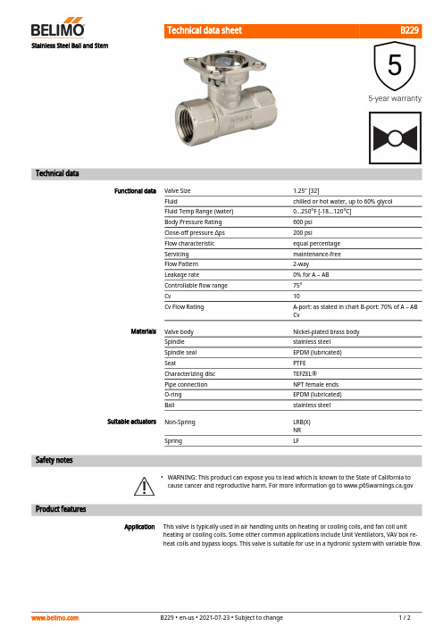
B229•ApplicationStainless Steel Ball and StemTechnical dataFunctional dataValve Size 1.25" [32]Fluidchilled or hot water, up to 60% glycol Fluid Temp Range (water)0...250°F [-18...120°C]Body Pressure Rating 600 psi Close-off pressure ∆ps 200 psiFlow characteristic equal percentage Servicing maintenance-free Flow Pattern 2-way Leakage rate0% for A – AB Controllable flow range 75°Cv10Cv Flow RatingA-port: as stated in chart B-port: 70% of A – AB CvMaterialsValve body Nickel-plated brass body Spindle stainless steel Spindle seal EPDM (lubricated)SeatPTFE Characterizing disc TEFZEL®Pipe connection NPT female ends O-ring EPDM (lubricated)Ballstainless steel Suitable actuators Non-Spring LRB(X)NR SpringLFSafety notesWARNING: This product can expose you to lead which is known to the State of California to cause cancer and reproductive harm. For more information go to Product featuresThis valve is typically used in air handling units on heating or cooling coils, and fan coil unit heating or cooling coils. Some other common applications include Unit Ventilators, VAV box re-heat coils and bypass loops. This valve is suitable for use in a hydronic system with variable flow.B229 Flow/Mounting detailsTwo-way valves should be installed with thedisc upstream.DimensionsDimensional drawingsLRB, LRXType DN Weight [kg][kg]B229320.60A B C D E F H1H29.4" [239] 3.7" [95]7.2" [184] 6.3" [161] 1.3" [33] 1.3" [33] 1.2" [30]0.6" [15]LFA B C D E F8.3" [211] 3.7" [95] 6.6" [167] 5.6" [142] 1.8" [46] 1.8" [46]ARB N4, ARX N4, NRB N4, NRX N4A B C D E F11.4" [289] 3.7" [95]7.8" [199]7.1" [181] 3.1" [80] 3.1" [80]LRB24-SR-T Modulating, Non-Spring Return, 24 V, for DC2...10 V or 4...20 mATechnical dataElectrical data Nominal voltage AC/DC 24 VNominal voltage frequency50/60 HzPower consumption in operation 1.5 WPower consumption in rest position0.2 WPower consumption for wire sizing 3 VATransformer sizing 3 VA (class 2 power source)Electrical Connection Screw terminal (for 26 to 14 GA wire)Overload Protection electronic thoughout 0...90° rotationFunctional data Operating range Y 2...10 VOperating range Y note 4...20 mA w/ ZG-R01 (500 Ω, 1/4 W resistor)Input Impedance100 kΩ for 2...10 V (0.1 mA), 500 Ω for 4...20 mAPosition feedback U 2...10 VPosition feedback U note Max. 0.5 mADirection of motion motor selectable with switch 0/1Manual override external push buttonAngle of rotation90°Angle of rotation note adjustable with mechanical stopRunning Time (Motor)default 90 s, variableNoise level, motor35 dB(A)Position indication Mechanically, pluggableSafety data Degree of protection IEC/EN IP54Degree of protection NEMA/UL NEMA 2Enclosure UL Enclosure Type 2Agency Listing cULus acc. to UL60730-1A/-2-14, CAN/CSAE60730-1:02, CE acc. to 2014/30/EUListed to UL 2043 - suitable for use in airplenums per Section 300.22(C) of the NEC andSection 602 of the IMCQuality Standard ISO 9001Ambient temperature-22...122°F [-30...50°C]Storage temperature-40...176°F [-40...80°C]Ambient humidity Max. 95% RH, non-condensingServicing maintenance-freeWeight Weight 1.1 lb [0.50 kg]LRB24-SR-TServicingAccessoriesElectrical accessoriesDescriptionType Battery backup system, for non-spring return models NSV24 US Battery, 12 V, 1.2 Ah (two required)NSV-BAT Auxiliary switch 1 x SPDT add-on S1A Auxiliary switch 2 x SPDT add-onS2AFeedback potentiometer 140 Ω add-on, grey P140A GR Feedback potentiometer 1 kΩ add-on, grey P1000A GR Feedback potentiometer 10 kΩ add-on, grey P10000A GR Feedback potentiometer 2.8 kΩ add-on, grey P2800A GR Feedback potentiometer 500 Ω add-on, grey P500A GR Feedback potentiometer 5 kΩ add-on, greyP5000A GRElectrical installationINSTALLATION NOTESProvide overload protection and disconnect as required.Actuators may be connected in parallel. Power consumption and input impedance must beobserved.Actuators may also be powered by DC 24 V.Only connect common to negative (-) leg of control circuits.A 500 Ω resistor (ZG-R01) converts the 4...20 mA control signal to 2...10 V.Actuators are provided with a numbered screw terminal strip instead of a cable.Meets cULus requirements without the need of an electrical ground connection.Warning! Live electrical components!During installation, testing, servicing and troubleshooting of this product, it may be necessary to work with live electrical components. Have a qualified licensed electrician or other individual who has been properly trained in handling live electrical components perform these tasks. Failure to follow all electrical safety precautions when exposed to live electrical components could result in death or serious injury.Wiring diagrams2...10 V / 4...20 mA ControlInstallation notesDimensions。
Mogas阀门产品介绍

- 1 -MOGAS 解决方案最佳性能,最好的服务,最高的价值 自1973年起,MOGAS 工业公司就开始制作应用于苛刻工况条件下使用的全金属密封球阀,并且广泛应用于炼油、石油、化工、电站、采矿等行业的重要部位。
MOGAS 以最先进的技术,针对炼油和石化工业 研发了C 系列阀门,用以确保过程控制中严酷工况条件下的可靠操控。
MOGAS 将继续不断地进行研究和革新,通过改进球体及阀座的表面加硬工艺等来实现MOGAS 过程控制领域的解决方案。
MOGAS在过程控制领域中解决问题 如今,炼油行业中复杂的工况对阀门的要求:可靠性高, 能长周期连续地使用。
• 紧急关断、隔离 • 极端条件下应用:如高温并伴随多固体颗粒介质、焦化介质、强磨损和腐蚀及侵蚀性介质 • 减少意外停车和降低维护成本 • 提高人员及环境的安全 MOGAS 阀门在过程领域应用 从最初安装至今已经超过10年,这台阀门仍然在这个高温高压的工况下保持着良好的性能。
Mogas 阀门独特的球体与阀座配对研磨工艺,确保球体与阀座金属密封面的100%密合。
这台8” 2500# MOGAS 阀门在安装12年后的首次打开检查。
尽管聚合物介质的粘稠性很强,这台阀门依然能够正常操作而未受损害,随后它继续投入正常运行。
炼油工艺及装置 FCCU 催化裂化 Visbreaking & Coking 减粘裂化及焦化 Heavy Oils 重油 Gasification / Liquefaction 气化/液化 Catalyst Slurry, Injection 催化剂浆液,注射济 Debutanized Bottoms 脱丁二烯 Waste Heat Recovery 废热回收 Emergency Shutdowns 紧急关断 UOP UOP 工艺 S-Zorb 汽油脱硫 Continuous Platforming Process 连续重整工艺 Hydrocracking 加氢裂化 石化 / 化工工艺及装置 Acetic Acid, Acetic Anhydride 醋酸,无水醋酸 Aluminum Catalyst 含铝催化剂 Caustic Sodamite 腐蚀性碳酸液 Ethylene Di-Chloride 二氯化乙烯 K-Resins, Molten Lead 树脂,熔铅 Phosgene Gas 光气(碳酰氯) Polyethylene, Polypropylene 聚乙烯、聚丙烯 VCM, TPA, PTA 氯乙烯, 精对笨二甲酸特殊应用 Supercritical CO 2 Extraction 超临界CO 2抽取 Hot Gases 热气 Rapid Open/Close Operation 快开、快关 Aerospace, Food Processing 航空宇宙,食品工艺- 2 -MOGAS 的质量控制质量保证 MOGAS 工业公司乐于提供优于其它球阀生产商的产品和产品保证。
煤化工球阀标准件尺寸
煤化工球阀标准件尺寸
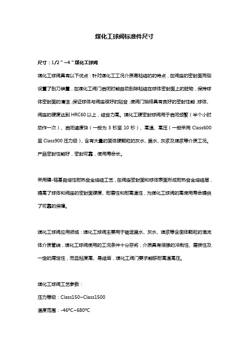
尺寸:1/2"~4"煤化工球阀
煤化工球阀具有以下优点:针对煤化工工况介质易粘结的的特点,在阀座的密封面两侧设置了刮刀装置,在煤化工阀门启闭时能自动刮除粘结在球体密封面上的脏物,保持球体密封面的清洁,保证球体与阀座很好的贴合,使阀门始终具有良好的密封性能;球体、阀座的硬度达到HRC60以上,结合力高。
煤化工硬密封球阀用于启闭频繁(半个小时动作一次)、启闭速度快(一般为3秒至10秒)、高温、高压(一般采用Class600至Class900压力级)、含有大量的固体硬颗粒的灰水、黑水、灰浆及煤浆等介质工况。
产品密封性能好,密封可靠,使用寿命长。
采用镍-铬基自熔性耐热合金熔结工艺,在阀座密封面和球体表面形成耐热合金熔结层,提高了球体和阀座的密封面硬度、耐磨性和耐高温性,为煤化工球阀的高使用寿命提供了可靠的保障。
煤化工球阀应用领域:煤化工球阀主要用于输送黑水、灰水、煤浆等含固体颗粒的混流体介质管线,煤化工球阀使用的工况条件十分恶劣,介质具有很强的冲刷性、磨损性及一定的腐蚀性,而且粘度高、易结垢,煤化工阀门要求能够耐高温高压。
煤化工球阀工艺参数:
压力等级:Class150~Class1500
温度范围:-46ºC~680ºC
阀门结构:铸件、锻件、二片式、三片式。
阀体材料:碳钢、不锈钢、双相钢
内件材料:F304、F316、F51、F52、17-4PH、Inconel 连接方式:RF、RJ、MF、BW
驱动方式:手动、气动、电动、蜗轮传动等。
球阀配件(注脂阀、单向阀、排污阀、螺堵)样本
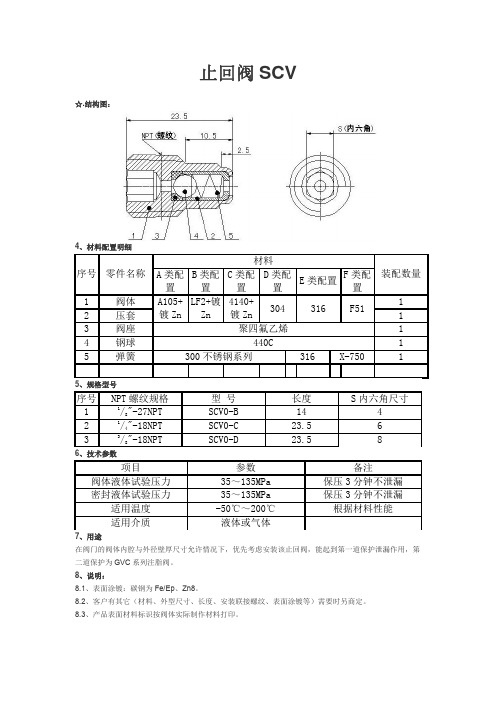
适用介质
液体或气体
1.7、用途: 阀门的阀座及阀杆的密封部位,可以加装该注脂阀。当密封部位因磨损或其他原因产生泄漏时,通过注脂 阀注入密封脂,起到暂时的密封作用,以便及时采取补救措施。
1.8、说明: 1.8.1、表面涂镀:碳钢为 Fe/Ep、Zn8。 1.8.2、客户有其它(材料、材料规格、外型尺寸、长度、安装联接螺纹、表面涂镀等)需要时另商定。 1.8.3、产品表面材料标识按阀体与阀帽实际制作材料打印。 1.8.4、又名称为带帽注脂(油)阀。
304
A105+镀 LF2+镀 4140+镀
Zn
Zn
Zn
304
410/420410/420410/420 304
440C 440C 440C 440C
E 类配 置 316 316 316
316
316 316 440C
F 类配置 装配数量
F51
1
Monel
1
F51
1
F51
1
F51
1
X-750
1
Monel
密封液体试验压力
35~135MPa
保压 3 分钟不泄漏
气体试验压力
0.6MPa
保压 3 分钟不泄漏
适用温度
-50℃~200℃
根据材料性能
适用介质
液体或气体
1.7、用途 适用安装阀门的阀体下部,阀门内腔排放气体及小量污物。 1.8、说明: 1.8.1、表面涂镀:碳钢为 Fe/Ep、Zn8。 1.8.2、客户有其它(材料、材料规格、外型尺寸、长度、安装联接螺纹、表面涂镀等)需要时另商定。 1.8.3、产品表面材料标识按阀体实际制作材料打印。
2.8、说明: 2.8.1、表面涂镀:碳钢为 Fe/Ep、Zn8。 2.8.2、客户有其它(材料、材料规格、外型尺寸、长度、安装联接螺纹、表面涂镀等)需要时另商定。 2.8.3、产品表面材料标识按阀体与阀帽实际制作材料打印。 2.8.4、0 型圈密封槽密封配合的尺寸也可根据客户要求制作。 2.8.5、又名称为带帽注脂(油)阀。
- 1、下载文档前请自行甄别文档内容的完整性,平台不提供额外的编辑、内容补充、找答案等附加服务。
- 2、"仅部分预览"的文档,不可在线预览部分如存在完整性等问题,可反馈申请退款(可完整预览的文档不适用该条件!)。
- 3、如文档侵犯您的权益,请联系客服反馈,我们会尽快为您处理(人工客服工作时间:9:00-18:30)。
Engineered Solutions for Isolation and ControlValves for Oil & Gas IndustriesSevere Operating Conditions.Critical Safety Operations.Dependability in Remote Locations.All these factors are key concerns for oil & gas equipment used in upstream, midstream and downstream processes. MOGAS metal-seated isolation and rotary control valves are built for punishing conditions. We understand the crucial need for absolute shutoff and reliable pressure and flow control. Our ongoing application-specific research and development—coupled with in-the-field customer assistance, valve analysis and maintenance / repair service—provides a high level of confidence and support.Advanced production techniques and pipeline processesare creating a demand for not only a new way ofoperating, but new types of equipment and valves.Production and pipeline components are expected tolast longer in order to maximize return on investments—and recognize the true total cost of ownership. This is where MOGAS products excel by outlasting traditional “throw-away” valves, performing reliably in extreme conditions,and being supported with field services you cancount on.FlexStream Innovation Bi-directional Flow Control Gas Flow Control Control Systems Designed In-House Reduced Footprint Oil & Gas Industry OverviewSolutions for Challenging EnvironmentsMOGAS metal-seated ball valves have proven successful in these applications and more:Cavern Fill and WithdrawalCompressor Anti-Surge Dryer Sequence (Mol-Sieve)Emergency Shut Down (ESD)First Stage SeparationGas Metering / Gathering ControlHigh Integrity Pressure Protection Systems (HIPPS)High Pressure Gas InjectionLNG Feed GasMain Gas Storage Flow ControlPlant DepressurizationPositive Isolation TandemSevere Pressure Reduction Control …while handling these conditions and more:High pressure drops Erosion Fugitive emissionsHigh velocity Liquefied gasMulti-phase crudeSour gasHydrate formations Noise limitations Vibr a tionCommon Features for the MOGAS C-Series Valve Line1 Accepts floating ball or trunnion ball design• Rotating ball does not displace volume or solids• Straight-through bore path protects sealing surfaces 2 Pressure-energized sealing• Seat springs maintain constant sealing contactbetween ball and seats• Allows for thermal expansion of trim• Metal seats wipe sealing surface of ball clean duringoperation 3 Wide seat sealing surface • Matched ball and seat sets provide total sealing contact for reliable isolation • Greater sealing contact area withstands minor scratches or abrasions4 Independent replaceable seats• Minimizes maintenance and repair costs5 Blowout-proof stem design• One piece design meets industry safety standards• Withstands severe service torques and maximumworking pressures6 Dual-guided stem design• Pressure-energized inner stem seals serve asthrust bearing and lower stem guide• Valve stem bushing serves as upper stem guide• Eliminates lateral movement of valve stem• Prevents media migration• Prevents stem packing leaks and risk offugitive emissions 7 Forged body & end connections • Greater wall thickness in critical areas provides longer valve life • 2 or 3-piece designs 8 Heavy-duty mounting flange • Machined after attaching to ensure precise stem alignment • Provides structural support for operator mounting • Provides visual inspection for confirmation ofball positionDesign Flexibility C-Series Valve Adapts to ApplicationsApplication Specific Features Seat designs Engineered for maximum performance in application-specific conditions Live-loaded packing Ensures constant packing energization Prevents stem packing leaks and risk of fugitive emissions Body GasketsPressure energized body gasket available to meet industry codes Materials Application-specific materials available, including exoticsExtends valve lifeCoatingsApplication-specific coatings provide enhanced erosion and corrosion resistance Liners and inlaysLiners and inlays can be applied to the through-bore or wetted surfaces Purge portsPurge ports are available for recommended periodic maintenance End connections Available end connections include flanged, welded, hub/clamp or RTJ 7668514324Application Specific DesignProvides Tailored Trim SolutionsControl for Extreme TemperaturesMetal-seated floating ball designed for temperatures >400 °FControl for Precision ModulationMetal-seated trunnion ball designed for temperatures <400 °FDesigned for Reliable IsolationMetal-seated floating ball designed for on/off applications•Pressure energized sealing, plus o-ring sealing •Variable control trim •Unlimited rangeability •Pressure Drop Ratio: >0.3•Size Range: 3 to 42 inch (80 to 1050 dn)•Temperature Range: -58 to 400 °F (-50 to 205 °C)• Pressure Classes: ASME 300 – 2500•Pressure energized sealing •Application-specific seat designs •Replaceable metal seats •Wide seat-sealing surface •Uni-directional or bi-directional sealing •Size Range: 1/2 to 36 inch (12 to 900 dn)•Temperature Range: -58 to 1652 °F (-50 to 900 °C)•Pressure Classes: ASME 300 – 4500 & API 6A•Pressure energized sealing •Variable control trim •Unlimited rangeability •Pressure Drop Ratio: >0.3•Size Range: 1/2 to 36 inch (12 to 900 dn)•Temperature Range: 400 to 1652 °F (205 to 900 °C)• Pressure Classes: ASME 300 – 4500 & API 6Aenergized sealingenergized sealing upstream seat ball design downstream seat sealingseatsball design control trim energized sealing upstream seat control trim ball designdownstream seatRotary Control TechnologiesFlexibility for Demanding EnvironmentsFlexStream technology uses a varying number of passageways engineered within the bore, custom designed to suit high pressure differential applications—providing better control of velocity / noise / vibration / erosion / cavitation.Variable trim technology tailors the percentage of filled bore to application-specific requirements. These examples show a range from 10 percent filled to 100 percent filled.Variable Trim TechnologyFlexible design comes from the variable construction ofthe internal trim. The trim is custom engineered to suit highpressure differential (∆P) applications by changing:• the number of openings• the style of letdown passages (straight-through ortortuous path)• the percentage of the bore that is filled.Application-Specific DesignThe complete valve assembly can be manufactured asa floating or trunnion ball design in a 2-piece or 3-pieceforged body construction, using a variety of corrosionresistant materials and coatings to meet the demands ofsevere process flow components.Controlling VelocityPressure can be reduced by turning the fluid flow through aright angle, which absorbs energy and controls velocity. Bycascading the pressure over a number of right angle turns,the pressure drop at each stage is evenly distributed. Thetortuous path expands at each right angle turn to ensurethat any increases in volume (due to pressure reduction)are accounted for, and velocity does not increase throughthe passageway—even though the fluid may be expanding,eliminating any potential erosion. The larger the pressuredrop, the more turns are required to control velocity.The MOGAS family of control valve technologies gives you complete flexibility for your specific application. The patented FlexStream ® technology expands upon the MOGAS ball valve’s proven strengths by adding the capabilities of precision modulation , exceptionally high rangeability and characterization .Sample of Computational Fluid Dynamics Accurate SizingAs with most control valves, the initial sizing and selectionprocess are carried out on customized computer software.Often incomplete requirements can result in impropersizing—providing opportunities for control valve failures.MOGAS has developed a customer-friendly sizing programwhich has been verified by an authorized third party foraccuracy, taking into account the guidelines provided bythe relevant ISA and IEC standards developed for controlvalve selection.The final selection process takes into account a combinationof information provided by the computer and applicationengineering knowledge provided by MOGAS. In-houseComputational Fluid Dynamics (CFD) are used to preciselydetermine the amount of letdown stages needed per application.Unprecedented Flexibility In addition to the features and benefits that come with all MOGAS isolation valves, FlexStream rotary control technology provides:• Pressure control of gases, multi-phase fluids and liquids • Custom trim engineered for high ΔP applications • Precision modulation • High rangeability and characterization • Multi-stage letdown • Limitation of velocity and vibration • Elimination of cavitation • Reduction of noise • Reduction of flashing erosion • Often smaller dimensional envelope than a traditional control valve • Greater Cv per inch compared to competition • Dependable emissions control • Proprietary sizing programIn addition to the features and benefits of a MOGAS isolationvalve, FlexStream rotarycontrol technology addsprecision modulation,high rangeability and characterization.Proven CoatingsNot All Coatings are EqualHarsh sands. Abrasive pipe scale. Dangerous entrapped gases.Each of these conditions can greatly affect the operations of mechanical equipment. The coatings used in the oil & gas industries (O&G) are often critical to not only the performance of the valve, but also the safety of personnel in that particular environment.Often the success of a coating depends upon proper selection of the basematerial and the coating, along with the method in which the coating isapplied—all as a complete system. MOGAS offers a range of mechanically andmetallurgically bonded coatings, applied with absolute accuracy for optimumthickness while maintaining precise design tolerances and dimensions.Through MOGAS, a wide selection of coatings are available to best serve eachparticular application. Coatings must handle a variety of challenges such aserosion, corrosion, pitting, wear, material build-up, etc. The abrasive nature ofcertain media and gaseous agents create serious operating challenges in theoil & gas market—challenges that MOGAS meets head-on with experience,world class engineering and the very latest in material science.MOGAS Coating RecommendationsEnvironment Concern Materials SolutionNote: Coating application methodology (spray & fused, HVOF, plasma,laser, etc.) is determined by application-specific conditions.© Copyright 07/2014 MOGAS Industries, Inc. Valves for Oil & Gas IndustriesResearch and DevelopmentTo ensure the best coatings solutions are available for our customers, MOGAS has an ongoing research & development program that includes: • continual field investigations• coupon testing (with traceability to each coating batch)• laboratory analysis• collaborative alliances with selected authorized coaters As part of ongoing research and development for coatings, MOGAS continually analyzes samples for strength and durability. Some examples of our testing and evaluation includes:• Abrasion tests• Slurry erosion tests • Micro hardness tests • Adhesion tests • Corrosion tests • Porosity analysis • Impact testing• Residual stress analysisMOGAS is known worldwide for its dedicated researchin coatings and material science.Continual lab testing and evaluation confirms adhesion, compatibility and wear for maximumperformance.Hardness and sensitivity to cracking are verified using Vickers indent microhardness testing.Using proprietary software programs, coating porosity is analyzed and validated.Fugitive Emissions ControlMost pipeline and process plants must adhere to strict legislative and safety requirements (such as ISO 15848-2) regarding fugitive emissions. Under these conditions, leaks to atmosphere—no matter how small—can grow into large Designed for SafetyEnsuring Confidence and Reducing RisksFire Tested for Dependable PerformanceFire in process plants can cause disastrous consequences—thus the necessity for various industry standards and specific end user requirements. The operation of valves, while in the midst of flames and extreme heat, is asignificant part of any plant’s safety program. MOGAS ball valves are designed to withstand the punishing effects of emergency fire situations.Several sizes and ASME classes of MOGAS valves have been fire tested and qualified to meet these stringentrequirements. Whether API standard or particular customer fire test specifications, MOGAS works with end users to ensure all testing procedures are adamantly followed. After the burn is completed, both the operability and the performance of the valve are evaluated. When fire testing is complete, all documentation and certifications are available for review.Recently a 4-inch ASME 1500 Class MOGAS valve, alongwith a 10-inch ASME 600 Class valve, were sent overseas for a customer-specificfire test.This 4-inch ASME 1500 Classball valve was surrounded by fire for a pre-determinedamount of time.After timerequirements were met, the fire was extinguished according to safetyprocedures.The final step in the fire test was verifying the ability to operate the valve and documenting the performance of the valve. The MOGAS valve not only passed on the first attempt, but exceeded the customer’s criticalrequirements.Quality Assurance / Quality ControlMOGAS maintains a fully implemented and certified Quality Assurance / Quality Control program. While MOGAS is certified to ISO 9001:2008 standards, we also reference many industry organizations for standards, codes and approvals, such as:• AP I• ASME• ATEX• CRN• D I N• FC I• GOST • IEC (SIL)• I SA • I SO • NBB I • PED MOGAS is dedicated to maintaining and continually improving their Quality Management System to satisfy the requirements of their customers and applicable industry standards.Emergency ShutdownAn Emergency Shut Down valve (also referred to as ESV , ESD, or ESDV) is an actuated valve designed to stop the flow of hazardous fluids or gases upon the detection of a dangerous event. This provides protection to people, equipment or the environment. ESD valves are required by law on any equipment placed on an offshore drilling rig to prevent catastrophic events.Key features include:• Metal-seated sealing• Designed to handle thermal shock • Proven fire-safe design • Tight shut-off• Anti-blowout proof stem• Compact Design• Suitable for fast acting response actuation• Certified design for use in SIL 3 applicationsFlare systemThe objective of a flare system is to burn waste gases that are eitheruneconomical to recover / retain—or released during planned or unplannedover-pressuring of plant equipment. Waste gases are released to the flare via flare headers and burned as they exit the flare stack.One of the major safety issues addressed with utilizing a dependable isolation valve is flashback protection. In this situation, absolute tight shut-off is required. However if de-pressurization is needed, a reliable severe service rotary control valve may be necessary. MOGAS offers both isolation and / or control valves for important process safety associated with flare systems.Positive Isolation Design (Double Block & Bleed)This valve arrangement usually involves an isolation valve in combination with a bleed / vent valve that will then interface with other components farther down the pipe. This sequence is used to first isolate / block the upstream flow from reaching downstream components and then bleed off / vent any remaining trapped inline flow. Positive isolation valves that are used in severe service must withstand extreme conditions with dependable, repeatable metal-to-metal sealing designs.A MOGAS positive isolation design can either consist of two isolation valves with a spool piece in-between (with a bleed port), or can be constructed as one of our customized, uniquely engineered Max-Series using two balls contained within one body. Piping configurations, process conditions and material requirements will usually drive the design choice.This 3-inch tandem valve was customized for positive isolation (double block & bleed) service. (The bleed port is not visible here.)Designed for SafetyEnsuring Confidence and Reducing RisksRequired ResultsValves that can isolate high pressures, entrained particulates, and the harshest of environments, such as sour gas, in a variety of wellhead, well fracture, distribution and manifold applications.ProcessThese valves are expected to handle some of toughest operating conditions in the Oil & Gas industry. Therefore they must be designed and manufactured to meet the stringent API 6A requirements in terms of materials, quality, inspection, cycle duty and safety levels—and must be certified to receive an API licensed monogram.Performance Features• A high degree of safety is required to ensure that environment and operators are protected.• Recessed metal seats are shielded from continual exposure to the process flow and particulate erosion• Ball is wiped clean with each operation of the valve by sharp leading edges of seat ring dismissing particulate build-up• Robust forged bodies and end connections have greater wall thickness in critical areas• Heavy duty mounting bracket minimizes stresses and maintains precise stem alignment• Blow-out proof stem is fully supported• Dual delta gasket sealing between the body and end connect as well as the body and bonnet protect against any body leakage• Packing area is protected from potential particulate erosion• Live loaded packing ensures constant packing energization • Application-specific materials and proprietary coatings guard against corrosive and abrasive conditions• Quick-quarter turn operation of non-rising stem does not pull destructive particles through the interior diameter of packing area• Sealing surfaces (ball and seat face) are in permanent contact throughout its 90-degree operationDesigned for API Spec 6AFloating Ball ValveThis 10,000 psi floatingball valve has been designed in accordance with API Spec 6A.MOGAS has been granted authorization from the American Petroleum Institute to use the API Spec 6A monogram for product specification levels 1 through 3; License number 6A-1466.Gas InjectionMOGAS Valve ApplicationsRequired ResultsValves that can handle high pressures, entrained particulates, and harsh environments, such as sour gas, during a variety of methods used to increase production of gas and oil reservoirs and extend the life of conventional wells. ProcessThese valves are used during EOR (Enhanced Oil Recovery) and EGR (Enhanced Gas Recovery) methods which are used to substantially improve extraction efficiencies and maximize well output. After primary and secondary recovery methods are applied, this tertiary recovery introduces fluids or gases (miscible carbon dioxide, oxygen, air or steam) that reduces viscosity and improves flow. Like valves designed for API Spec 6A, they are expected to handle some of toughest operating conditions in the Oil & Gas industry. Therefore they are designed and manufactured to meet the stringent API 6A requirements in terms of materials, quality, inspection, cycle duty and safety levels and are certified to receive an API licensed monogram.Performance Features• Recessed metal seats are shielded from continual exposure to the process flow and particulate erosion• Robust forged bodies and end connections have greater wall thickness in critical areas• Heavy duty mounting bracket minimizes stresses and maintains precise stem alignment• Blow-out proof stem is fully supported• Dual delta gasket sealing between the body and end connect as well as the body and bonnet protect against any body leakage• Packing area is protected from potential particulate erosion• Live loaded packing ensures constant packing energization• Quick-quarter turn operation of non-rising stem does not pull destructive particles through the interior diameter of packing area• Sealing surfaces (ball and seat face) are in permanent contact throughout its 90-degree operationPRESSUREGAS INJECTIONT O / F R O MTOCOMPRESSOR T O / F R O M P I P E L I N EGas Transport & StorageMOGAS Valve ApplicationsRequired ResultsEquipment needed for this application are both control valves that can handle different pressures, pressure drops and media with entrained particulates, as well as full bore isolation valves with repeatable dependable tight shut-off.ProcessValves used in distribution pipelines and underground storage must able to operate dependably when called upon. Often located in remote locations or subject to environmental elements, maintenance is also a concern. MOGAS pipeline and storage valves are available as either floating or trunnion designs, depending upon size and operating conditions. In the rotary control technology, the let-down stages are manufactured in either the ball or seat components. These control valves must handle bi-directional differential pressures forapplications that require filling and withdrawing through the same control valve. In addition, they must be able to provide exceptional rangeability across a wide range of pressure or flow cases.Performance Features• Recessed metal seats are shielded from continual exposure to the process flow and particulate erosion• Packing area is protected from potential particulate erosion• Two hard coated and lapped metal thrust bearings serve as a pressureenergized inner stem seal and prevent galling between body, stem and the inner stem seals.• Quick quarter-turn operation of non-rising stem does not pull destructive particles through the interior diameter of packing area• Live loaded packing ensures constant packing energization• Sealing surfaces (ball and seat face) are in permanent contact throughout its 90-degree operation• Secondary stem bearing guide eliminates movement and packing deformation caused by side-loading of stem by the actuator• Non-rising stem design allows for greater number of cycles and mitigates fugitive emissions• Repairability can be handled quickly with trim sets comprised of minimal componentsThese large-bore MOGAS valves have been operating successfully for years in this major underground storage cavern.Dryer Sequence (Molecular Sieve) MOGAS Valve ApplicationsRequired ResultsValves that can handle high and low temperatures, entrained particulates, thermal shock and high cycling with dependable shut-off over many years of service. ProcessMolecular sieve dehydration (MSD) is used to remove water from natural gas. There are multiple columns filled with desiccant and the gas feed is cycled through adsorption, regeneration and cooling vessels.Performance Features• Recessed metal seats are shielded from continual exposure to the process flow and particulate erosion• Ball is wiped clean with each operation of the valve by sharp leading edges of seat ring dismissing particulate build-up• Packing area is protected from potential particulate erosion• Materials and coatings on ball and seats have compatible thermal growth rates (rapid temperature changes) to prevent bond failure and valve seizure • Quick quarter-turn operation of non-rising stem does not pull destructive particles through the interior diameter of packing area• Live loaded packing ensures constant packing energization, even after several thermal cycles• Sealing surfaces (ball and seat face) are in permanent contact throughout its 90-degree operation• Withstands thermal shock with sufficient clearance between seat back and seat pocket• Non-rising stem design allows for greater number of cycles and meets EPA VOC emissions standardsFEED GAS 1FEED GAS 2FEED GAS 2nd STAGEOPTIONAL PROCESSING FLOWREGENERATIONCompressor Anti-SurgeMOGAS Valve ApplicationsRequired ResultsRotary control valves that can handle high ΔP in liquids, gases and multi-phase flow to combat energy absorption, velocity, cavitation and noise. In certain installations they must also withstand high temperatures as well as high pressures, corrosive applications, abrasive entrained particulates and other critical conditions. These control valves must provide accurate positioning during compressor commissioning and throughout the normal operation of demand changes on the compressor.ProcessCompressors are a crucial part of many processes where the media requires compression in order to move along the system. These compressors are set for particular conditions where any instability in the control valve will create a system trip. In the event of a trip, the control valve must open extremely fast to ensure that the gas is recycled around the compressor to avoid internal damage tothe compressor. Anti-Surge / recycle control valves should always be designed to minimize the valve’s internal forces that may work against precise control, stability and fast operation. If the anti-surge control valves are inadequate, costly investments in the compressor will be jeopardized or even destroyed. Performance Features• FlexStream’s rangeability is rated at greater than 500.1• MOGAS control valves can stroke to a fully open position in less than a second• When not in full-stroke mode, MOGAS control valves can still meet stroking time and stability requirements.• Recessed metal seats are shielded from continual exposure to the process flow and particulate erosion• Noise abatement up to 85dBA during recycle, 105 dBA at trip instance• Packing area is protected from potential particulate erosion• Materials and coatings on ball and seats have compatible thermal growth rates (rapid temperature changes) to prevent bond failure and valve seizure • Quick quarter-turn operation of non-rising stem does not pull destructive particles through the interior diameter of packing area• Live loaded packing ensures constant packing energization, even after several thermal cycles• Sealing surfaces (ball and seat face) are in permanent contact throughout its 90-degree operation• Non-rising stem design allows for greater number of cycles• Stem integrity is maintained with anti-blowout stem design while fugitive emissions are mitigatedValve Type ComparisonFeature MOGAS FlexStream®Linear Globe ValveStroke Quarter-turn gives excellent stability Over-travel results in poor control Quarter-turn gives excellent control Plug mass results in poor stability Design Designed for overcapacity Limited overcapacity capability Compact construction Infrastructure issues due to sizeand weightRangeability Virtually unlimited Inefficient use of spaceRotary construction efficiently uses space Design not suited to compressor curve (linear)HIPPSMOGAS Valve ApplicationsRequired ResultsRelief valve configurations that can provide protection involving large flow rates and high pressures. These arrangements usually include full port emergency shutdown valves, sensors, fail-safe actuation, flow control technology, and other coordinated components.ProcessHigh Integrity Pressure Protection Systems (HIPPS) are designed to reduce the risk that can arise if the pressure of a system exceeds its design pressure. With today’s requirements for higher flow rates and pressures, the ability to lock-in pressure using a performance-based, non-descriptive framework and life-cycle data is required. These systems include emergency shutdown valves, pressure sensors, fail safe actuation, partial-stroke testing and a logic solver—all with built-in redundancy in a skid mounted package.These HIPPS systems are used in the Oil and Gas Industry as well as LNG facilities and Transport & Storage systems to ensure the safety of pipelines, piping, vessels and process packages. Regardless of what application, any containment loss due to overpressurization is a critical issue.Critical Pressures Require Serious SolutionsHIPPS ensure that a continuous measure of safety is deployed to reduce the operational risk associated with the probability of a hazardous event. This is handled by examining the probability of failure on demand (PFD), using Safety Instrumented System (SIS) to calculate the Safety Integrity Level (SIL). The SIL corresponds to a certain tolerable PFD.Dependable Isolation is a MustThese systems provide protection against overpressurization in situations when the actual pressure could exceed the design pressure.There are three main components of a HIPPS safety system:1. The sensors, which are used to detect high pressure (a hazardous situation)2. The logic solver, which determines the proper steps to take to alter the finalelement3. The final element, which performs the necessary steps to bring the processback to a safe state of being. The final element involves the valve, actuator and solenoids.A typical MOGAS HIPPS package includes the following:• Emergency shutdown valves• Pressure sensor voting system• Solid state PLC or hard-wired relay logic system• SIL 3 FM certified IEC 61508• Class 1 Zone 2 IIC T4• Fail-safe actuator• Skid-mounted system can be provided, if desired。