SY58025UMG中文资料
YS8152B RS485 硫化氢传感器说明书

YS8152BRS485 硫化氢传感器说明书使用前请详细阅读说明书YS8152B硫化氢气体传感器为RS485总线式传感器,采用RS485接口,标准MODBUS-RTU协议,可实现多点同时监测,组网并远距离传送数据。
适用于各种场所,尤其适用于公共场合、工厂、仓库等需要硫化氢气体监控的场所。
为便于工程组网及工业应用,本模块采用工业广泛使用的MODBUS-RTU通讯协议,支持二次开发。
用户只需根据通讯协议即可使用任何串口通讯软件实现模块数据的查询和设置。
YS8152B 硫化氢传感器采用专业测试硫化氢气体浓度传感器探头作为核心检测器件;具有测量范围宽、精度高、线性度好、通用性好、使用方便、便于安装、传输距离远、价格适中等特点。
硫化氢是一种易燃的酸性气体,无色,低浓度时有臭鸡蛋气味。
硫化氢是一种重要的化学原料。
用于合成荧光粉,电放光、光导体、光电曝光计等的制造。
有机合成还原剂。
用于金属精制、农药、医药、催化剂再生、通用试剂、制取各种硫化物。
硫化氢气是强烈的神经毒素,并能引起人们的嗅觉麻痹。
吸入少量高浓度硫化氢可于短时间内致命。
低浓度的硫化氢对眼、呼吸系统及中枢神经都有影响。
在空气中含量超过50PPM就会影响人们的身健康,当超过200PPM时就会直接危害人类的生命安全。
为保护自然环境和工业生产安全,针对性开发出这一款硫化氢气传感器。
硫化氢气浓度实时显示,提醒及时检查并打开通风或采取安全措施。
并可订做带自动控制输出功能,自动打开风机换气或报警。
并对多种有害气体(一氧化碳、氨气)也有很好的敏感性,有利于及时避免火灾等各种隐患。
也可以使用在工厂、仓库等需要硫化氢气体浓度监测控制的场合。
注意事项:1、避免暴露在有机硅蒸气中。
如果传感器的表面吸附了有机硅蒸气,传感器的敏感材料会被包裹住,抑制传感器的敏感性,并且不可恢复。
传感器要避免暴露其在硅粘接剂、发胶、硅橡胶、腻子或其它含硅塑料添加剂可能存在的地方。
2、避免暴露在高腐蚀性的环境。
uct530+技术参数

uct530+技术参数一、概述uct530是我司最新研发的一款高性能工业级USB转串口转换器,适用于数据传输、设备通讯等领域。
本技术文档详细介绍了uct530的技术参数、使用说明、注意事项及常见问题,以便用户更好地了解和掌握该产品。
二、技术参数1.接口类型:USB(兼容USB2.0/1.1)2.串口号:COMx(x为1-99)3.数据传输速率:最高可达115200bps4.串口协议:RS-232/RS-485(可切换)5.工作电压:DC5V(典型值)6.功耗:小于2W7.工作环境:温度-20℃~70℃;湿度5%~95%RH8.尺寸:68mmx24mmx12mm9.封装形式:LX16P+(SOT23)三、使用说明1.连接设备:将uct530通过USB线与电脑连接。
2.配置串口参数:在电脑上安装uct530驱动程序,根据设备实际情况设置串口号和波特率等参数。
3.数据传输:通过uct530实现串口数据的高效传输,可实现文本、图像、音频等数据的串口传输。
4.断电保护:uct530具有完善的断电保护机制,当电源断开时,内部数据不会丢失,保证了数据的完整性。
5.固件升级:用户可通过在线升级的方式,对uct530进行固件升级,以获取新功能和修复已知问题。
四、注意事项1.使用USB线连接电脑和uct530时,请确保线缆完好无损,以免影响数据传输。
2.在设置串口参数时,请根据实际设备情况设置,避免出现通讯问题。
3.在高温、高湿等恶劣环境下使用时,请注意设备散热和通风,以免影响设备性能。
4.请定期更新uct530驱动程序和固件,以获取更好的使用体验和性能。
五、常见问题及解决方案1.问题:驱动安装失败怎么办?解决方案:请确保USB线缆完好无损,并重新安装驱动程序。
如果问题仍然存在,请联系客服寻求帮助。
2.问题:通讯速率不达标怎么办?解决方案:请检查串口号是否正确,并确认设备波特率设置是否正确。
如果问题仍然存在,请联系客服寻求帮助。
AMD微雾分离器系列商品介绍说明书
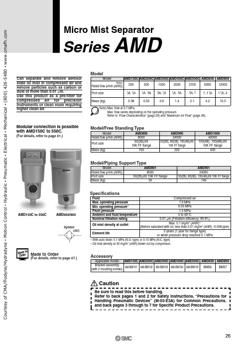
SymbolAMDMicro Mist SeparatorSeries AMDCan separate and remove aerosol state oil mist in compressed air and remove particles such as carbon or dust of more than 0.01 μm.Use this product as a pre-filter for compressed air for precision instruments or clean room requiring higher clean air.Specifications0.05 MPa 1.5 MPa FluidMax. operating pressure Min. operating pressure ∗Proof pressureAmbient and fluid temperature Nominal filtration rating Element lifeCompressed air1.0 MPa 5 to 60°C0.01 μm (Filtration efficiency: 99.9%)Oil mist density at outlet Max. 0.1 mg/m 3 (ANR)∗(Before saturated with oil, less than 0.01 mg/m 3 (ANR) ≈0.008 ppm)2 years (1 year for flange type)or when pressure drop reached 0.1 MPa∗ With auto drain: 0.1 MPa (N.O. type) or 0.15 MPa (N.C. type)∗ Oil mist density at 30 mg/m 3 (ANR) blown out by compressor.Modular connection is possible with AMD150C to 550C.(For details, refer to page 61.)AMD150C to 550C AMD650/850Made to Order(For details, refer to page 67.)CautionBe sure to read this before handling.Refer to back pages 1 and 2 for Safety Instructions, “Precautions for Handling Pneumatic Devices” (M-03-E3A) for Common Precautions, and back pages 3 through to 7 for Specific Product Precautions.o u r t e s y o f C M A /F l o d y n e /H y d r a d y n e ▪ M o t i o n C o n t r o l ▪ H y d r a u l i c ▪ P n e u m a t i c ▪ E l e c t r i c a l ▪ M e c h a n i c a l ▪ (800) 426-5480 ▪ w w w .c m a f h .c o mHow to Order OptionsSeries AMD ourtesyofCMA/Flodyne/Hydradyne▪MotionControl▪Hydraulic▪Pneumatic▪Electrical▪Mechanical▪(8)426-548▪www.cmafh.comHow to OrderA M D 10A M D 90, 91A M D 850A M D 80 , 81A M D 650A M D 550C A M D 450C A M D 350CA M D 250CA M D 150CAMD 65010Free standing type AMD800/810 to 10 0Piping support type 2000AMD 82001AMD 8Maximum Air FlowMax. flow lineModel SelectionSelect a model in accordance with the following procedure taking the inlet pressure and the max. air flow rate into consideration.(Example) Inlet pressure: 0.6 MPaMax. air flow rate: 5 m 3/min (ANR)1.Obtain the intersecting point A of inlet pressure and max. air flow rate in the graph.2. The AMD650 is obtained when the max. flow line is above the in-tersecting point A in the graph.Body size8910Body size89DescriptionWith differential pressure gauge (GD40-2-01)With differential pressure switch(With indicator, 125 VAC, 30 VDC)With IN-OUT flangeWith differential pressure gauge(GD40-2-01) and IN-OUT flangeN.C., N.O. auto drain, drain piping type White vaseline specificationsPage for details —P.68P.68P.69P.69X6X37X15X17P.70P.70X26X12Symbol Made to Order(“How to Order” and the applicable models are different from those shown on this page. Be sure to refer to “Made to Order”.)—Nil60150(6B)JIS 10K FF flange2050(2B)JIS 10K FF flange 3080(3B)JIS 10K FF flange 40100(4B)JIS 10K FF flange Port sizeSizeApplicable body sizeAMD800, 810AMD9 0AMD10 0Symbol00With manual drain cock 10With auto drainTypeDescription SymbolThread typeNilRc F G NNPTType Symbol Type01With manual drain cock 11With auto drainDescriptionSymbolAuto drain specifications/Option Auto drain specifications Option Option Auto drain specificationsD J R DJ T R Applicable modelAMD650AMD850N.O. auto drainDrain guide IN-OUT reversal directionTWith element service indicator14Auto Drain Specifications/Option Combinations: Available: Not availablePort size10142011122SizeApplicable body size650850Symbol Body size650850∗1Bracket is included,(but not assembled).AccessoryDescription —Bracket ∗1Symbol BNil Auto drain ∗2DescriptionDrain cock (Without auto drain) ∗3N.O. auto drainSymbol DNil∗2 Refer to “Auto Drain Specifications/Option Combinations”.∗3Body size 850 is equipped with a ball valve (Rc3/8 femalethreaded). Mount a piping adapter IDF-AP609 (page 62) to the ball valve if NPT3/8 female threaded is required.With element service indicatorOption ∗2Drain guide female threaded ∗4IN-OUT reversal direction 14Description—TJ R Symbol Nil∗4Drain piping and piping for a stopvalve such as ball valve are required.AMD650/850AMD801/811/9 1Port size2050(2B)JIS 10K FF flange 3080(3B)JIS 10K FF flange 40100(4B)JIS 10K FF flangeSizeApplicable body sizeAMD8 1AMD9 1SymbolNote)Make sure to select a model that has the max. flow line abovethe obtained intersecting point. With a model that has the max. flow line below the obtained intersecting point, the flow rate will be exceeded, thus leading to a problem such as being unable to satisfy the specifications.M a x . a i r f l o w r a t e (m 3/m i n (A N R ))Note) Refer to “How to Order BowlAssembly” on page 63.Micro Mist Separator SeriesAMDo u r t e s y o f C M A /F l o d y n e /H y d r a d y n e ▪ M o t i o n C o n t r o l ▪ H y d r a u l i c ▪ P n e u m a t i c ▪ E l e c t r i c a l ▪ M e c h a n i c a l ▪ (800) 426-5480 ▪ w w w .c m a f h .c o mAMD150C AMD250C AMD350C AMD450C AMD850AMD80 /81AMD650AMD10 0AMD550C AMD9 0/9 1Note) Compressed air over max. flow line in the table below may not meet the specifications of the product.It may cause damage to the element.Flow Characteristics /Select the model taking the max. flow capacity into consideration. ( Element oil saturation Initial condition)P r e s s u r e d r o p (M P a )Air flow rate (l /min (ANR))P r e s s u r e d r o p (M P a )Air flow rate (l /min (ANR))P r e s s u r e d r o p (M P a )Air flow rate (m 3/min (ANR))P r e s s u r e d r o p (M P a )Air flow rate (l /min (ANR))P r e s s u r e d r o p (M P a )Air flow rate (l /min (ANR))P r e s s u r e d r o p (M P a )Air flow rate (l /min (ANR))P r e s s u r e d r o p (M P a )Air flow rate (m 3/min (ANR))P r e s s u r e d r o p (M P a )P r e s s u r e d r o p (M P a )P r e s s u r e d r o p (M P a )Air flow rate (m 3/min (ANR))Max. flow lineMax. flow lineMax. flow lineMax. flow lineMax. flow lineMax. flow lineMax. flow lineMax. flow lineMax. flow lineMax. flow lineSeries AMDo u r t e s y o f C M A /F l o d y n e /H y d r a d y n e ▪ M o t i o n C o n t r o l ▪ H y d r a u l i c ▪ P n e u m a t i c ▪ E l e c t r i c a l ▪ M e c h a n i c a l ▪ (800) 426-5480 ▪ w w w .c m a f h .c o mIN OUTElementConstructionAMD150C to 550C, AMD650AMD850AMD80 /81 /9 0/9 1/10 0OUTIN ∗ Element assembly: With gasket (1 pc.) and O-ring (1 pc.)∗ Refer to back page 6 for replacement of auto drain.∗ Element assemblies for Made to Order (X6, X12, X15, X17, X20, X26, X37) are same as those for standard (see the above table).∗ The AMD850 is aluminum casted.Note) Sight glass is indicated in the figure for easy understanding ofcomponent parts. However, it differs from the actualconstruction. Refer to dimensions on pages 31 through to 34 for details.Micro Mist Separator SeriesAMDo u r t e s y o f C M A /F l o d y n e /H y d r a d y n e ▪ M o t i o n C o n t r o l ▪ H y d r a u l i c ▪ P n e u m a t i c ▪ E l e c t r i c a l ▪ M e c h a n i c a l ▪ (800) 426-5480 ▪ w w w .c m a f h .c o mAMD150C to 550CC: With auto drain (N.C.)D: With auto drain (N.O.)OptionJ: Drain guide 1/4 female threadedCombination of D: With auto drain (N.O.) S, U: With differential pressure switch (with indicator)T: With element service indicatorDimensionsSeries AMDo u r t e s y o f C M A /F l o d y n e /H y d r a d y n e ▪ M o t i o n C o n t r o l ▪ H y d r a u l i c ▪ P n e u m a t i c ▪ E l e c t r i c a l ▪ M e c h a n i c a l ▪ (800) 426-5480 ▪ w w w .c m a f h .c o m18076853111601502015114.512136160402533341032205537M a i n t e n a n c e s p a c eAMD150C to 550C, AMD650T: With element service indicatorDrainINOUTINOUT(Accessory)Bracket Auto drainD: With auto drain (N.O.)OptionJ: Drain guide 1/4 female threaded201/4 female threaded34Drain cock: Blackø10 one-touch fittingDimensionsMicro Mist Separator SeriesAMDo u r t e s y o f C M A /F l o d y n e /H y d r a d y n e ▪ M o t i o n C o n t r o l ▪ H y d r a u l i c ▪ P n e u m a t i c ▪ E l e c t r i c a l ▪ M e c h a n i c a l ▪ (800) 426-5480 ▪ w w w .c m a f h .c o m22011061818422022018024131530348464101204246158Rc 3/8 female threadedM a i n t e n a n c e s p a c e DrainBracket (Accessory)2 x port sizeAMD850T: With element service indicatorAuto drainD: With auto drain (N.O.)for AMD850Option233/8 female threadedDimensionsSeries AMDOUTININ OUTo u r t e s y o f C M A /F l o d y n e /H y d r a d y n e ▪ M o t i o n C o n t r o l ▪ H y d r a u l i c ▪ P n e u m a t i c ▪ E l e c t r i c a l ▪ M e c h a n i c a l ▪ (800) 426-5480 ▪ w w w .c m a f h .c o mLabelLabelDrain≈≈ORIENTATIONORIENTATIONAMD801/811/9 1AMD800/810/9 0/10 0Model500A720M16 x l 400Anchor bolt M20 x l 500AMD800/810AMD9 0Connection (Flange)50(2B), 80(3B)JIS 10K FF flange50(2B), 80(3B), 100(4B)JIS 10K FF flange 100(4B), 150(6B)JIS 10K FF flange870M20 x l 500AMD10 0300øB 560745200(8B)øC 400550300D3003001300E 132013801430F 148016101520G 1585174020H2424ModelConnection (Flange)50(2B)JIS 10K FF flange50(2B), 80(3B), 100(4B)JIS 10K FF flange400A620AMD801/811AMD9 1280øB 445150(6B)øC 300(12B)760D795150E300270F5201033G13183H3887J9723 x øH holesDimensionsMicro Mist Separator SeriesAMDIN OUTIN OUTOUT INOUTINOUTo u r t e s y o f C M A /F l o d y n e /H y d r a d y n e ▪ M o t i o n C o n t r o l ▪ H y d r a u l i c ▪ P n e u m a t i c ▪ E l e c t r i c a l ▪ M e c h a n i c a l ▪ (800) 426-5480 ▪ w w w .c m a f h .c o m。
SY58028UMG资料
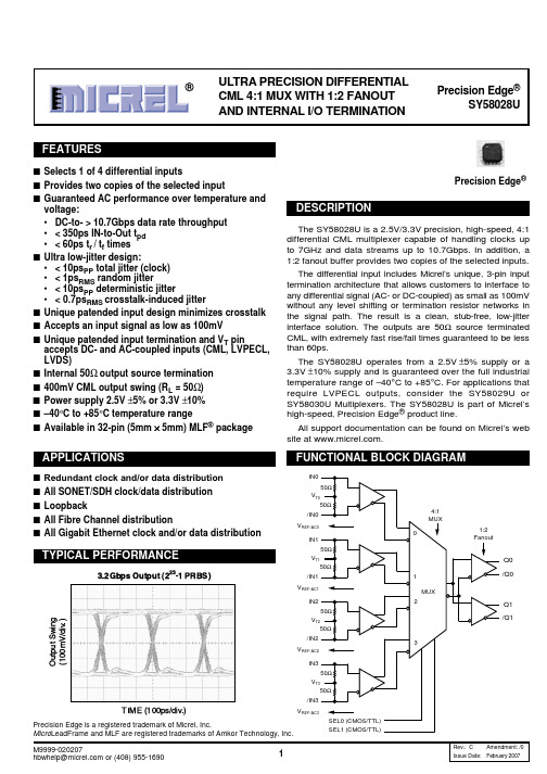
Lead Finish Sn-Pb Sn-Pb Pb-Free NiPdAu Pb-Free NiPdAu
23
Q0 /Q0
Ð1 PRBS)
Q1 /Q1
Output Swing
(100mV/div.)
VT2 50Ω /IN2 VREF-AC2 IN3 50Ω VT3 50Ω /IN3
TIME (100ps/div.)
3
VREF-AC3 SEL0 (CMOS/TTL) SEL1 (CMOS/TTL)
Rev.: C Amendment: /0
32 31 30 29 28 27 26 25
SY58028UMI SY58028UMITR(2) SY58028UMG(3) SY58028UMGTR(2, 3)
IN0 VT0 VREF-AC0 /IN0 IN1 VT1 VREF-AC1 /IN1
1 2 3 4 5 6 7 8 9 10 11 12 13 14 15 16
Ordering Information(1)
Part Number
GND VCC Q1 /Q1 VCC NC SEL1 VCC
Package Type MLF-32 MLF-32 MLF-32 MLF-32
Operating Range Industrial Industrial Industrial Industrial
1
Issue Date: February 2007
元器件交易网
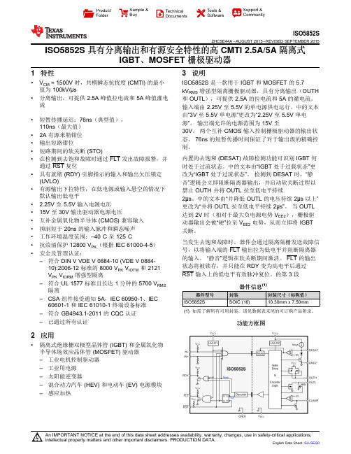
ISO5852S 具有分离输出和有源安全特性的高 CMTI 2.5A5A 隔离式IGBT、 MOSFET 栅极驱动器
4 修订历史记录
NOTE: Page numbers for previous revisions may differ from page numbers in the current version.
Changes from Original (July 2015) to Revision A
Page
• 已将特性“共模瞬态抗扰度 (CMTI) 最小值为 100kV/μs...”移动至列表顶部.............................................................................. 1 • 已从单页产品预览更改为完整数据表。 .................................................................................................................................. 1 • 已将说明 ................................................................................................................................................................................. 1 • 已将说明 ................................................................................................................................................................................. 1 • 已将说明 ................................................................................................................................................................................. 1 • 已更改说明.............................................................................................................................................................................. 1 • 更改了功能框图,在引脚 OUTL 上添加了 STO...................................................................................................................... 1
KR5805S中文资料
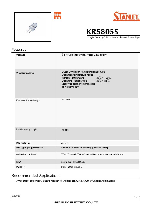
2004.10.27
Page 5
元器件交易网
KR5805S
Single Color φ5 Flush Mount Round Shape Type
Technical Data
Spectral Distribution
Relative Intensity vs. Wavelength Condition : Ta = 25℃, IF = 20mA
1.8 V 2.5 100 660 647 25 40 μA nm nm nm deg.
2004.10.27
Page 4
元器件交易网
KR5805S
Single Color φ5 Flush Mount Round Shape Type
Luminous Intensity Rank
元器件交易网
KR5805S
Features
Package φ5 Round shape type, Water Clear epoxy
Single Color φ5 Flush Mount Round Shape Type
Product features
・Outer Dimension φ5 Round shape type ・Operation temperature range. Storage Temperature :-30℃~100℃ Operating Temperature :-30℃~85℃ ・Lead–free soldering compatible ・RoHS compliant
S ymbol Absolute Ma x imum Ra ting s Pd IF IF R M ⊿ IF VR T opr T s tg 125 50 300 0.67 4 -30~ +85 -30~ +100
方正君逸M580双网隔离(USB)计算机介绍

方正君逸M580双网隔离计算机背景随着互联网时代的到来,网络信息技术的高速发展已彻底颠覆了传统的办公模式,大大提高的工作效率使我们无法再离开网络;与此同时,我们也正受到日益严重的来自网络的安全威胁,诸如网络的数据窃贼、黑客的侵袭、病毒发布者,甚至系统内部的泄密者。
信息安全已经成为各行业信息化建设中的首要问题。
面对这一严峻形势,国家保密局、中保委相继出台信息安全要求,明确规定涉密计算机信息系统必须与国际互联网或其他公共信息网实行物理隔离。
应运而生——方正君逸M580双网隔离计算机“极速安全方正为先”,方正科技倾力打造国内领先通过公安部、保密局、军队三方认证的双网隔离PC整机--方正君逸M580双网隔离计算机。
这款双网隔离计算机是根据政府、金融、企业等对网络与信息安全有特殊要求的机关、单位的需求,采用最新的双网隔离技术研发而成,该产品具有“双网快速切换”、“实时在线”、“安全易用”和“高兼容性”等特色,能够达到“网内网外,安全畅享”的效果。
安全性设计目标方正君逸M580隔离网计算机,融入了完整的终端安全体系结构设计概念,实现了内外网络的绝对的物理隔离,同时做到了网络隔离、硬盘数据隔离、内存隔离。
通过物理隔离的方式,在二个网间实时在线地、自由地切换时,保证计算机的数据在网络之间不被重用。
根据本产品设计方法:当计算机进入其中一个网络时,内部物理隔离部件保证被隔离的计算机硬盘、内存及相应网络相互不连通。
在转换网络时,正在运行的操作系统挂起并释放所拥有的资源,由隔离部件保存重要的信息,并唤醒另一个睡眠中的系统,恢复它的相关信息。
这样,计算机的硬件资源使用了对操作系统而言完全独立的硬件资源,并且这些资源在数据信息相互独立(包括内存,显存, 硬盘等),从而在数据上没有任何的泄漏。
功能特点⏹与隔离卡产品相比,切换时间由原来的120-180秒缩短至5-8秒⏹快速切换的同时,始终保留用户的网络工作现场环境⏹人性化开机界面,鼠标/键盘均可选择进入内外网系统⏹内外网系统切换时,对存储介质(光、软、U)作安全检测,提示用户取出介质⏹网络连接自动检测,如果内、外网线插反,系统自动提示错误并切断连接,防止意外数据泄漏。
ME2805型号高精度电压检测器说明书

ME2805Ultra-small package High-precision Voltage Detector with delaycircuit, ME2805 SeriesGeneral Description FeaturesME2805 Series is a series of high-precision voltage detectors with a built-in delay time generator of fixed time developed using CMOS process. Internal oscillator and counter timer can delay the release signal without external parts. Detect voltage is extremely accurate with minimal temperature drift. CMOS output configurations are available. ● Highly accuracy : ±1%● Low power consumption :TYP 0.9uA (V DD =3V) ● Detect voltage range :1.0V~6.5V in 0.1Vincrements● Operating voltage range :0.7V~7V● Detect voltage temperature characteristics :TYP±100ppm/℃● Output configuration : CMOSTypical Application● Power monitor for portable equipment such as notebook computers, digital still cameras, PDA, and cellular phones● Constant voltage power monitor for cameras, videoequipmentandcommunicationdevices.● Power monitor for microcomputers and resetfor CPUs.● System battery life and charge voltagemonitorsTypical Application CircuitPackage● 3-pin SOT23-3、SOT23Selection GuideME 2805X X GEnvironment markPackage:X Function Product Type Product Series MicroneX X Output Voltage X-SOT23M3-SOT23-3NOTE: If you need other voltage and package, please contact our sales staff.product series product descriptionME2805A263M3G V OUT =2.63V ;Rising edge detection ;Package :SOT23-3 ME2805A263XG V OUT =2.63V ;Rising edge detection ;Package :SOT23 ME2805A293M3G V OUT =2.93V ;Rising edge detection ;Package :SOT23-3 ME2805A293XG V OUT =2.93V ;Rising edge detection ;Package :SOT23 ME2805A308XGV OUT =3.08V ;Rising edge detection ;Package :SOT23 ME2805A463XG V OUT =4.63V ;Rising edge detection ;Package :SOT23Pin Configuration123123SOT-23SOT-23-3Pin AssignmentPIN Number Pin Name Function SOT-23-3/SOT-231 VSS Ground2 VOUT Output Voltage 3VDDInput VoltageBlock DiagramAbsolute Maximum RatingsPARAMETER SYMBAL RATINGSUNITS V IN Input Voltage V IN 8 V Output CurrentI OUT 50mA Output Voltage CMOS V OUT GND-0.3~V IN +0.3V Continuous Total PowerDissipationSOT-23-3 Pd 300 mW SOT-23250 Operating Ambient TemperatureT Opr -40~+85 ℃ Storage Temperature T stg -40~+125 ℃ Soldering temperature and timeT solder 260℃, 10sESDMM 400 V HBM4000VElectrical Characteristics(-V DET(S)=1.0V to 6.5V±2% ,Ta=25O C , unless otherwise noted)Parameter Symbol Conditions Min. Typ Max.UnitsTest circuitDetect Voltage (Output Voltage)-VDET --VDET(S)×0.99-VDET(S)-VDET(S)×1.01V1 HysteresisRangeVHYS - 0.03 0.06 0.1 VSupply Current ISSVDD=3V (below 2.5V) - 0.9 1.5uA2VDD=5V (2.5V-4.5V) - 1.4 2.8VDD=7V (4.5V-6.5V) - 1.8 3.6Output CurrentIoutN-chVDS=0.5V VDD=0.7V 0.01 0.19 --mA3IoutP-ch VDS=0.5V VDD=7V 1.7 3.4 --mA4OperatingvoltageVDD - 0.7 - 7 V 1 Delay timeTd1 VDD=-VDET+1V DS low 130 200 290 ms 1Td2 VDD=-VDET+1V DS high 110 220 330 us 5 Temperaturecharacteristics VDETTaVDET-∙∆-∆Ta∆=-40℃~ 85℃- ±100 ±350 ppm/℃ 1 Note:1、-VDET(S) :Specified Detection Voltage value2、-VDET :Actual Detection Voltage value3、Release Voltage:+VDET=-VDET+VHYSTest Circuits:1. 2.3. 4.5.Functional Description :1. Basic Operation: CMOS Output (Active Low)1-1. When the power supply voltage (VDD) is higher than the release voltage (+VDET), the Nch transistor is OFF andthe Pch transistor is ON to provide VDD (high) at the output. Since the Nch transistor N1 in Figure 1 is OFF, thecomparator input voltage isC B A C B R R R VDD R R ++∙+)(.1-2. When the VDD goes below +VDET, the output provides the VDD level, as long as VDD remains above thedetection voltage (–VDET). When the VDD falls below –VDET (point A in Figure 2), the Nch transistor becomes ON, the Pch transistor becomes OFF, and the VSS level appears at the output. At this time the Nchtransistor N1 in Figure 1 becomes ON, the comparator input voltage is changed to B AB R R VDD R +∙.1-3. When the VDD falls below the minimum operating voltage, the output becomes undefined, or goes to VDD whenthe output is pulled up to VDD.1-4. The VSS level appears when VDD rises above the minimum operating voltage. The VSS level still appearseven when VDD surpasses the –VDET, as long as it does not exceed the release voltage +VDET.1-5. When VDD rises above +VDET (point B in Figure 2), the Nch transistor becomes OFF and the Pch transistorbecomes ON to provide VDD at the output. The VDD at the OUT pin is delayed for Td due to the delay circuit.2. Delay Circuit2-1. Delay TimeThe delay circuit delays the output signal from the time at which the power voltage (VDD) exceeds the release voltage (+VDET) when VDD is turned on. The output signal is not delayed when the VDD goes below the detection voltage (–VDET). (Refer to Figure 2.) The delay time (t D) is a fixed value that is determined by a built-in oscillation circuit and counter.2-2. DS Pin (ON/OFF Switch Pin for Delay Time)The DS pin should be connected to Low or High. When the DS pin is High, the output delay time becomes short since the output signal is taken from the middle of counter circuit (Refer to Figure 3).Directions for use:1、Please use this IC within the stated maximum ratings. Operation beyond these limits may cause degrading orpermanent damage to the device.2、When a resistor is connected between the V DD pin and the input with CMOS output configurations, oscillation mayoccur as a result of voltage drops at R IN if load current(I OUT) exists.(refer to the Oscillation Description(1) below)3、When a resistor is connected between the V DD pin and the input with CMOS output configurations, oscillation mayoccur as a result of through current at the time of voltage release even if load current(I OUT) does not exist. (refer to the Oscillation Description(2) below)4、With a resistor connected between the V DD and the input, detect and release voltage will rise as a result of the IC’ssupply current flowing through the V DD pin.5、In order to stabilize the IC’s operations, please ensure that V DD pin’s input frequency’s rise and fall times are morethan several u Sec/V.Oscillation Description:1、 Output current oscillation with the CMOS output configurationWhen the voltage applied at IN rises, release operations commence and the detector’s output voltage increase.Load current(I OUT) will flow at R L. Because a voltage drop(R IN*I OUT) is produces at the R IN resistor, located between the input(IN) and the V DD pin. The load current will flow via the IC’s pin. The voltage drop will also lead toa fall in the voltage level at the V DD pin. When the V DD pin voltage level falls below the detect voltage level, detectoperations will commence. Fllowing detect operations, load current flow will cease and since voltage drop at R IN will disapper, the voltage level at the V DD pin will rise and release operations will begin over again. Oscillation may occur with this “release-detect-release” repetition. Further, this condition will also appear via means of a similar mechanism during detect operations.2、 Oscillation as a result of through currentSince the ME2805 series are CMOS IC’s, through current will flow when the IC’s internal circuit switching operates(during release and detect operations). Consequently, oscillation is liable to occur as a result of drops in voltage at the through current’s resistor(R IN) during release voltage operations.(refer to diagram 2) since hysteresis exists during detect operations, oscillation is unlikely to occur.Type Characteristics1、SUPPLY CURRENT VS. AMBIENT TEMPERATUREVDD=5V,-VDET=2.63V VDD=2.5V,-VDET=2.63VIss VS.TEMP0.30.60.91.21.51.82.12.42.7-16102030405060708090100110120TEMP(℃)I s s (u A )Iss VS.TEMP0.20.40.60.811.2-16102030405060708090100110120TEMP(℃)I s s (u A )2、SUPPLY CURRENT VS. INPUT VOLTAGE3、DETECT,RELEASE VOLTAGE VS. AMBIENTTEMPERATURE-VDET=2.63V (T=25℃) -VDET=2.63VIss VS VDD0.511.522.500.511.52 2.53 3.54 4.55 5.566.577.5VDD(V)I s s (u A )VDET VS TEMP2.542.562.582.62.622.642.662.682.72.72-16102030405060708090100110120TEMP(℃)V D E T (V )-VDET +VDE T4、 OUTPUT CURRENT VS. INPUT VOLTAGEN-ch VDS=0.5V,-VDET=2.63V P-ch VDS=0.5V,-VDET=2.63VIout(N) VS. VDD0246810120.20.50.71 1.2 1.7 2.2 2.5VDD(V)I o u t (m A )T=85℃T=-15℃T=23℃I o u t (P ) V S. V00.511.522.533.542.73.2 3.544.555.56V D D (V )I o u t (mT =-15℃T =23℃T =85℃Packaging Information● SOT23DIMMillimetersInchesMinMax Min Max A 0.9 1.2 0.0354 0.0472 A1 0 0.14 0.0000 0.0055 A2 0.9 1.05 0.0354 0.0413 b 0.28 0.52 0.0110 0.0205 c 0.07 0.23 0.0028 0.0091 D 2.8 3.0 0.1102 0.1181 e1 1.8 2.0 0.0709 0.0787 E 1.2 1.4 0.0472 0.0551 E1 2.22.60.08660.1024e 0.95(TYP) 0.0374(TYP) L 0.55(TYP)0.0217(TYP)L1 0.25 0.55 0.0098 0.0217θ 08° 0.00008°c10.25(TYP)0.0098(TYP)● SOT23-3DIMMillimetersInchesMinMax Min Max A 0.9 1.2 0.0354 0.0472 A1 0 0.14 0.0000 0.0055 A2 0.9 1.05 0.0354 0.0413 b 0.28 0.52 0.0110 0.0205 c 0.07 0.23 0.0028 0.0091 D 2.8 3.0 0.1102 0.1181 e1 1.8 2.0 0.0709 0.0787 E 1.2 1.4 0.0472 0.0551 E1 2.22.60.08660.1024e 0.95(TYP) 0.0374(TYP) L 0.55(TYP)0.0217(TYP)L1 0.25 0.55 0.0098 0.0217 θ 08° 0.00008°c1 0.25(TYP)0.0098(TYP)V04 Page 11 of 11 ME2805● The information described herein is subject to change without notice.● Nanjing Micro One Electronics Inc is not responsible for any problems caused by circuits or diagrams described herein whose related industrial properties, patents, or other rights belong to third parties. The application circuit examples explain typical applications of the products, and do not guarantee the success of any specific mass-production design.● Use of the information described herein for other purposes and/or reproduction or copying without the express permission of Nanjing Micro One Electronics Inc is strictly prohibited.● The products described herein cannot be used as part of any device or equipment affecting the human body, such as exercise equipment, medical equipment, security systems, gas equipment, or any apparatus installed in airplanes and other vehicles, without prior written permission of Nanjing Micro One Electronics Inc.● Although Nanjing Micro One Electronics Inc exerts the greatest possible effort to ensure high quality and reliability, the failure or malfunction of semiconductor products may occur. The user of these products should therefore give thorough consideration to safety design, including redundancy, fire-prevention measures, and malfunction prevention, to prevent any accidents, fires, or community damage that may ensue.。
赛钛客飞行摇杆产品培训(精)
Saitek
系统支持及售后
接口类型:USB,支持即插即用。 适用操作系统:Windows XP, XP64, Vista 32位及64 位系统 推荐游戏软件:微软模拟飞行2004、微软模拟飞FSX 、 X-Plane、太平洋飞将、战地2、炽天使系列、鹰 击长空 售后服务:三个月包换、两年保修
Saitek
X52飞行摇杆
• • • • • 基本参数相同。 采用中置单弹簧。 提供单色灯光调节。 液晶屏不具备可编程功能。 在游戏里移动曲线表现细腻缓慢 ,略微缓慢与X52PRO。
Saitek
X52飞行摇杆
媒体价:980元 建议售价:850元
摇杆基础参数 左手控制器: • 力度可调的油门/制动调节器 • 2个动作按钮 • 1个八方向视角切换键 • 2个摸拟旋钮 • 2个鼠标仿真控制键 • 1个鼠标滚轮 • 1个滑动调节器 • 1套综合功能液晶显示屏 右手飞行摇杆: • 5个开火键 • 1个小拇指开关键 • 1个导弹发射键 • 2个8方向帽式开关 • 1个模式切换旋钮 • 3D旋转脚舵设计 • X、Y轴采用霍尔磁感应电位器
Saitek
系统支持及售后
接口类型:USB,支持即插即用。 适用操作系统:Windows XP, XP64, Vista 32位及 64位系统 推荐游戏软件:微软模拟飞行2004、微软模拟飞行 FSX、 X-Plane、太平洋飞将、战地2、炽天使系 列、鹰击长空 售后服务:三个月包换、两年保修
Saitek
Saitek
双手杆基本功能示意图
• 基本功能XYZ轴和AV8R一样 • 苦力帽:一共有3个,主苦力帽 用于观察视野。副苦力帽可作 为功能键使用。 • 功能键:可随意定制游戏里的 各种功能。 • 旋钮1轴、旋钮2轴、滑块轴: 可以设置飞机配平、襟翼等游 戏中提供的其他轴功能 • Z轴锁定:当使用专业脚舵的 时候,锁定摇杆上的尾舵功能 • 3档模式切换、小指模式切换是 配合SST使用,可以实现6倍摇 杆功能按键。 • 组合键:是在游戏中,通过此 键+苦力帽的配合来选择SST的 配置文件用的。
3M绝缘粉介绍

电气绝缘应用领域据数十年来的统计,数量超过几亿台的电机在其转子和定子的绝缘防护方面都成功的使用了Scotchcast 产品。
今天Scotchcast产品领域已经拓展到磁线防护,母排保护及磁环保护等。
Scotchcast 产品大都通过了UL实验室对于电气绝缘系统的认证,小功率电机和其他需要认证的生产客户可以从中受益,其中最高温度等级达到Class C(200°C)。
ﻫScotchcast环氧粉末产品采用100%固体单组分系统,其优势包括:快速固化,优异的电气性能,强大的抗热冲击及抗机械冲击性能,坚固的划伤抵御能力,良好的附着力,优秀的抗化学及潮湿腐蚀能力,适应高低温度的流动特性和优异的静电涂敷能力。
这类树脂产品由先进的熔结-共混工艺生产,保证了每个单一粉末颗粒都包含用于固化和提供上述性能的所有有效组分。
5555电气绝缘树脂著名绝缘树脂产品,一种绿色,快速热固化的单组分粉末环氧树脂,能用静电流化床,静电喷涂或流化床浸涂的方法涂敷,应用于各种类型的绝缘电枢、定子、汇流条和和环形铁芯的绝缘保护。
它拥有极其优异的耐温性能,通过了UL认证的耐温等级H级。
5230N电气绝缘树脂3M电气绝缘树脂5230N是一种蓝色,快速热固化的单组分粉末环氧树脂,它是为各种类型的底材提供持续的湿热稳定性、化学稳定性的绝缘涂层。
并且通过了UL认证。
260电气绝缘树脂3M电气绝缘树脂260是通用性的绿色、快速热固化的单组分双酚A型粉末环氧树脂。
是为各种类型的底材提供持续的抗热冲击和抗冲击性能、湿热稳定性、化学稳定性的绝缘涂层。
通过UL认证。
260 8G电气绝缘树脂ﻫ3M电气绝缘树脂260 8G是通用性的绿色、快速热固化的单组分双酚A型粉末环氧树脂。
它拥有更快的固化速度,适用于更快的成产效率,是为各种类型的底材提供持续的抗热冲击和抗冲击性能、湿热稳定性、化学稳定性的绝缘涂层。
260 C-free电气绝缘树脂3M电气绝缘树脂260C-free是通用性的绿色、快速热固化的、不含重金属铬的环保绿色单组分双酚A型粉末环氧树脂。
齿轮油的基本知识

车辆齿轮油发展历程
1944年 美国军队建立2105A标准 1946年 MIL-L-2105A改进了锈蚀及磨损性能 1957年 API GL-1至GL-6等一系列标准被引入 1959年 MIL-L-2105A要求以L-37、L-42代替L-19、L-20 1962年 美军MIL-L-2105B的所有分项测试被接受 1965年 API GL-4、GL-5标准发布 1969年 API GL-6标准发布 1976年 引进MIL-L-2105C的L-33的7天锈蚀测试 1987年 MIL-L-2105D的深度精制油被接纳 1995年 MT-1出台 1996年 MIL-PRF-2105E规格包括了传动系统、油封性能等 2003年? PG-2
弹性液体动力润滑
油膜 的厚度并不足以完全的使表面分开 部分金属表面发生不平滑接触 发生温和的磨损 负荷是由油和表面的接触承受 磨擦起缘于表面的接触和油的作用
界面润滑(Boundary Lubrication)
金属表面有相当大程度的接触 发生较为严重的磨损 负荷主要是由表面接触来承受
齿轮油的简介
齿轮传动机构
齿轮机构是机械中最主要的一种传动机构。 传递功率范围大 传动效率较高 可传递在任意两轴之间的运动和动力。 运动和动力的传递是在齿轮机械中每对啮合面的相互作 用、相对作用中完成的 避免机件直接摩擦在齿轮工作面之间完成,需要润滑剂 将工作面隔开,以保持齿轮机构的工效和延长使用寿命。 齿轮油就是主要的润滑剂。
工业齿轮油粘度分类
GB3141粘度 40℃运动粘度, AGMA 粘度等级 ISO 粘度等级
等级
mm2/s
68
61.2~74.8
2
VG 68
100
90~110
3
TOP222Y中文资料
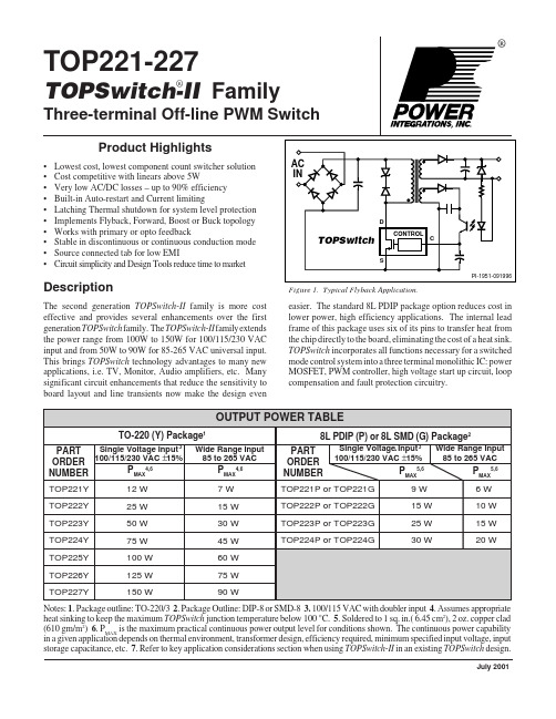
2
D 7/01
PI-1935-091696
Tab Internally Connected to SOURCE Pin
9W
6W
TOP222Y
25 W
15 W
TOP222P or TOP222G
15 W
10 W
TOP223Y
50 W
30 W
TOP223P or TOP223G
25 W
15 W
TOP224Y
75 W
45 W
TOP224P or TOP224G
30 W
20 W
TOP225Y
100 W
60 W
TOP226Y
Three-terminal Off-line PWM Switch
Product Highlights
• Lowest cost, lowest component count switcher solution • Cost competitive with linears above 5W • Very low AC/DC losses – up to 90% efficiency • Built-in Auto-restart and Current limiting • Latching Thermal shutdown for system level protection • Implements Flyback, Forward, Boost or Buck topology • Works with primary or opto feedback • Stable in discontinuous or continuous conduction mode • Source connected tab for low EMI • Circuit simplicity and Design Tools reduce time to market
TAS5352A中文资料
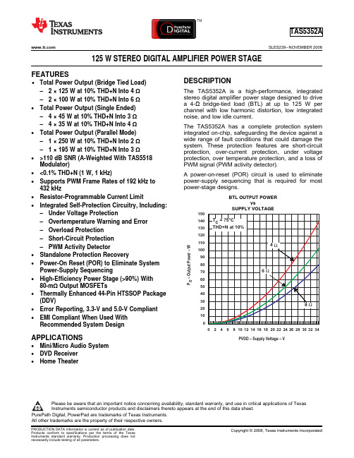
150
140 TC = 75°C 130 THD+N at 10%
120
110
4Ω
100
90
80
70
6Ω
60
50
40
30 8Ω
20
10
0 0 2 4 6 8 10 12 14 16 18 20 22 24 26 28 30 32 34
PVDD – Supply Voltage – V
APPLICATIONS
• Mini/Micro Audio System • DVD Receiver • Home Theater
DESCRIPTION
The TAS5352A is a high-performance, integrated stereo digital amplifier power stage designed to drive a 4-Ω bridge-tied load (BTL) at up to 125 W per channel with low harmonic distortion, low integrated noise, and low idle current.
The TAS5352A has a complete protection system integrated on-chip, safeguarding the device against a wide range of fault conditions that could damage the system. These protection features are short-circuit protection, over-current protection, under voltage protection, over temperature protection, and a loss of PWM signal (PWM activity detector).
美孚佳特 570 化学品安全技术说明书
修订日期: 18 三月 2021SDS 编号:2008554XCN 最初编制日期: 7 Nov 2015版本:5.01______________________________________________________________________________________________________________________化学品安全技术说明书产品产品名称: 美孚佳特 570产品简介:基础油及添加剂产品代码: 201540105510, 606806推荐用途: 船用柴油机气缸油公司资料供应商:埃克森美孚( 中国 )投资有限公司美罗大厦17楼天钥桥路30号上海市 200030 中国二十四小时应急电话供应商联系电话电子邮件传真紧急情况概述:物理状态: 液体颜色: 褐色气味: 特有的根据法规指引(参阅第十五部分),本产品不属于危险品。
高压射向皮肤可能会造成严重的损伤过度接触会造成眼部、皮肤或呼吸刺激。
根据法规指引(参阅第十五部分),本产品不属于危险品。
含有: 磺酸钙可能产生过敏反应。
修订日期: 18 三月 2021SDS 编号:2008554XCN 最初编制日期: 7 Nov 2015版本:5.01______________________________________________________________________________________________________________________其它危险性信息:物理/化学危害无明显危害健康危害高压射向皮肤可能会造成严重的损伤过度接触会造成眼部、皮肤或呼吸刺激。
环境危害无明显危害注释: 在没有咨询专家的情况下,除第1部分规定的特定用途外,该产品不可用于其它任何目的。
健康研究已经表明,化学接触可能对人体健康造成潜在危害,这一点因人而异。
该产品被定义为混合物。
需要披露的有害物质或有害复合物名称CAS登记号#浓度*GHS 有害分类代码长链烷基苯酚硫化钙 68784-26-9 1 - < 5% H413磺酸钙 722503-68-6 0.1 - < 1% H317四丙烯基苯酚(74499-35-7&132752-19-3)保密 0.1 - < 1% H314(1C), H360(1B)(F),H400(M factor 10), H410(Mfactor 10)复合物中所含的需要披露的有害成分名称CAS登记号#浓度*GHS 有害分类代码2, 6-二叔丁基对甲基苯酚 128-37-0 0.1 - < 0.25% H400(M factor 1), H410(Mfactor 1)* 除气体外,所有组分的浓度均为重量百分比。
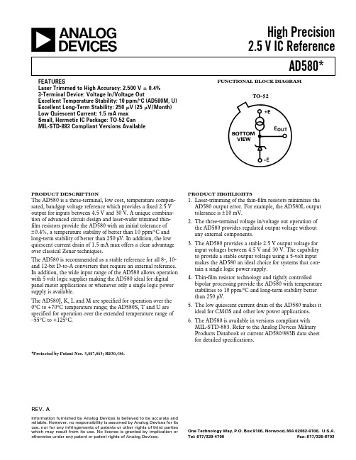
AD580_高精度2.5V基准电源
FUNCTIONAL BLOCK DIAGRAMREV.AInformation furnished by Analog Devices is believed to be accurate and reliable. However, no responsibility is assumed by Analog Devices for its use, nor for any infringements of patents or other rights of third parties which may result from its use. No license is granted by implication or otherwise under any patent or patent rights of Analog Devices.aHigh Precision 2.5 V IC ReferenceAD580*One Technology Way, P.O. Box 9106, Norwood, MA 02062-9106, U.S.A.Tel: 617/329-4700Fax: 617/326-8703FEATURESLaser Trimmed to High Accuracy: 2.500 V ؎ 0.4%3-Terminal Device: Voltage In/Voltage OutExcellent Temperature Stability: 10 ppm/؇C (AD580M, U)Excellent Long-Term Stability: 250 V (25 V/Month)Low Quiescent Current: 1.5 mA max Small, Hermetic IC Package: TO-52 Can MIL-STD-883 Compliant Versions AvailablePRODUCT DESCRIPTION The AD580 is a three-terminal, low cost, temperature compen-sated, bandgap voltage reference which provides a fixed 2.5 V output for inputs between 4.5 V and 30 V. A unique combina-tion of advanced circuit design and laser-wafer trimmed thin-film resistors provide the AD580 with an initial tolerance of ±0.4%, a temperature stability of better than 10 ppm/°C and long-term stability of better than 250 µV. In addition, the low quiescent current drain of 1.5 mA max offers a clear advantage over classical Zener techniques.The AD580 is recommended as a stable reference for all 8-, 10-and 12-bit D-to-A converters that require an external reference.In addition, the wide input range of the AD580 allows operation with 5 volt logic supplies making the AD580 ideal for digital panel meter applications or whenever only a single logic power supply is available.The AD580J, K, L and M are specified for operation over the 0°C to +70°C temperature range; the AD580S, T and U are specified for operation over the extended temperature range of –55°C to +125°C.*Protected by Patent Nos. 3,887,863; RE30,586.PRODUCT HIGHLIGHTSser-trimming of the thin-film resistors minimizes the AD580 output error. For example, the AD580L output tolerance is ±10 mV.2.The three-terminal voltage in/voltage out operation of the AD580 provides regulated output voltage without any external components.3.The AD580 provides a stable 2.5 V output voltage for input voltages between4.5 V and 30 V. The capability to provide a stable output voltage using a 5-volt input makes the AD580 an ideal choice for systems that con-tain a single logic power supply.4.Thin-film resistor technology and tightly controlled bipolar processing provide the AD580 with temperature stabilities to 10 ppm/°C and long-term stability better than 250 µV.5.The low quiescent current drain of the AD580 makes it ideal for CMOS and other low power applications.6.The AD580 is available in versions compliant with MIL-STD-883. Refer to the Analog Devices Military Products Databook or current AD580/883B data sheet for detailed specifications.AD580–SPECIFICATIONS(@ E IN = +15 V and +25؇C )Model AD580J AD580K AD580L AD580MMin Typ Max Min Typ Max Min Typ Max Min Typ Max Units OUTPUT VOLTAGE TOLERANCE(Error from Nominal 2.500 Volt Output)؎75؎25؎10؎10mV OUTPUT VOLTAGE CHANGET MIN to T MAX157 4.3 1.75mV85402510ppm/°C LINE REGULATION7 V ≤ V IN≤ 30 V 1.56 1.5422mV4.5 V ≤ V IN≤ 7 V0.330.3211mV LOAD REGULATION∆I = 10 mA10101010mV QUIESCENT CURRENT 1.0 1.5 1.0 1.5 1.0 1.5 1.0 1.5mA NOISE (0.1 Hz to 10 Hz)8888µV (p-p) STABILITYLong Term250250250250µV Per Month25252525µV TEMPERATURE PERFORMANCESpecified0+700+700+700+70°C Operating–55+125–55+125–55+125–55+125°C Storage–65+175–65+175–65+175–65+175°C PACKAGE OPTION*TO-52 (H-03A) AD580JH AD580KH AD580LH AD580MHModel AD580S AD580T AD580UMin Typ Max Min Typ Max Min Typ Max UnitsOUTPUT VOLTAGE TOLERANCE(Error from Nominal 2.500 Volt Output)؎25؎10؎10mVOUTPUT VOLTAGE CHANGET MIN to T MAX2511 4.5mV552510ppm/°CLINE REGULATION7 V ≤ V IN≤ 30 V 1.5622mV4.5 V ≤ V IN≤ 7 V0.3311mVLOAD REGULATION∆I = 10 mA101010mVQUIESCENT CURRENT 1.0 1.5 1.0 1.5 1.0 1.5mANOISE (0.1 Hz to 10 Hz)888µV (p-p)STABILITYLong Term250250250µVPer Month252525µVTEMPERATURE PERFORMANCESpecified–55+125–55+125–55+125°COperating–55+150–55+150–55+150°CStorage–65+175–65+175–65+175°CPACKAGE OPTION*TO-52 (H-03A) AD580SH AD580TH AD580UHNOTES*H = Metal Can.Specifications subject to change without notice.Specifications shown in boldface are tested on all production units at final electrical test. Results from those tests are used to calculate outgoing quality levels.All min and max specifications are guaranteed, although only those shown in boldface are tested on all production units.–2–REV. AAD580REV. A –3–ABSOLUTE MAXIMUM RATINGSInput Voltage . . . . . . . . . . . . . . . . . . . . . . . . . . . . . . . . . . .40V Power Dissipation @ +25°CAmbient Temperature . . . . . . . . . . . . . . . . . . . . . . .350 mW Derate above +25°C . . . . . . . . . . . . . . . . . . . . . . . 2.8 mW/°C Lead Temperature (Soldering 10sec) . . . . . . . . . . . . .+300°C Thermal ResistanceJunction-to-Case . . . . . . . . . . . . . . . . . . . . . . . . . . . .100°C Junction-to-Ambient . . . . . . . . . . . . . . . . . . . . . . .360°C/WAD580 CHIP DIMENSIONSAND PAD LAYOUTDimensions shown in inches and (mm).The AD580 is also available in chip form. Consult the factory for specifications and applications information.THEORY OF OPERATIONThe AD580 family (AD580, AD581, AD584, AD589) uses the “bandgap” concept to produce a stable, low temperature coefficient voltage reference suitable for high accuracy data ac-quisition components and systems. The device makes use of the underlying physical nature of a silicon transistor base-emitter voltage in the forward-biased operating region. All such transis-tors have approximately a –2 mV/°C temperature coefficient,unsuitable for use directly as a low TC reference; however,extrapolation of the temperature characteristic of any one of these devices to absolute zero (with emitter current proportional to absolute temperature) reveals that it will go to a V BE of 1.205volts at 0K, as shown in Figure 1. Thus, if a voltage could be developed with an opposing temperature coefficient to sum with V BE to total 1.205 volts, a zero-TC reference would result and operation from a single, low voltage supply would be possible.The AD580 circuit provides such a compensating voltage, V 1 in Figure 2, by driving two transistors at different current densities and amplifying the resulting V BE difference (∆V BE —which now has a positive TC); the sum (V Z ) is then buffered and amplified up to 2.5 volts to provide a usable reference-voltage output. Fig-ure 3 is the schematic diagram of the AD580.The AD580 operates as a three-terminal reference, which means that no additional components are required for biasing or cur-rent setting. The connection diagram, Figure 4 is quite simple.Figure 1.Extrapolated Variation of Base-Emitter Voltage with Temperature (I E αT), and Required Compensation,Shown for Two Different DevicesFigure 2. Basic Bandgap-Reference Regulator CircuitAD580REV. A–4–Figure 3.AD580 Schematic DiagramFigure 4.AD580 Connection DiagramVOLTAGE VARIATION VS. TEMPERATURESome confusion exists in the area of defining and specifying reference voltage error over temperature. Historically, references are characterized using a maximum deviation per degree Centi-grade; i.e., 10 ppm/°C. However, because of the inconsistent nonlinearities in Zener references (butterfly or “S” type charac-teristics), most manufacturers use a maximum limit error band approach to characterize their references. This technique mea-sures the output voltage at 3 to 5 different temperatures and guarantees that the output voltage deviation will fall within the guaranteed error band at these discrete temperatures. This ap-proach, of course, makes no mention or guarantee of perfor-mance at any other temperature within the operating tempera-ture range of the device.The consistent Voltage vs. Temperature performance of a typi-cal AD580 is shown in Figure 5. Note that the characteristic is quasi-parabolic, not the possible “S” type characteristics of clas-sical Zener references. This parabolic characteristic permits a maximum output deviation specification over the device’s full operating temperature range, rather than just at 3 to 5 discretetemperatures.Figure 5.Typical AD580K Output Voltage vs. TemperatureThe AD580M guarantees a maximum deviation of 1.75 mV over the 0°C to +70°C temperature range. This can be shown to be equivalent to 10 ppm/°C average maximum; i.e.,1.75mV max 70°C ×12.5V =10ppm /°C max averageThe AD580 typically exhibits a variation of 1.5 mV over thepower supply range of 7 volts to 30 volts. Figure 6 is a plot of AD580 line rejection versus frequency.NOISE PERFORMANCEFigure 7 represents the peak-to-peak noise of the AD580 from 1 Hz (3 dB point) to a 3 dB high end shown on the horizontal axis. Peak-to-peak noise from 1 Hz to 1 MHz is approximately 600 µV.Figure 6.AD580 Line Rejection PlotFigure 7.Peak-to-Peak Output Noise vs. FrequencyAD580REV. A–5–Figure 8.Input Current vs. Input Voltage (Integral Loads)THE AD580 AS A CURRENT LIMITERThe AD580 represents an excellent alternative to current lim-iter diodes which require factory-selection to achieve a desired current. This approach often results in temperature coefficients of 1%/°C. The AD580 approach is not limited to a specially selected factory set current limit; it can be programmed from 1 mA to 10 mA with the insertion of a single external resistor.The approximate temperature coefficient of current limit for the AD580 used in this mode is 0.13%/°C for I LIM = 1 mA and 0.01%/°C for I LIM = 13 mA (see Figure 9). Figure 8 displays the high output impedance of the AD580 used as a current lim-iter for I LIM= 1, 2, 3, 4, 5 mA.Figure 9.A Two-Component Precision Current LimiterTHE AD580 AS A LOW POWER, LOW VOLTAGEPRECISION REFERENCE FOR DATA CONVERTERSThe AD580 has a number of features that make it ideally suited for use with A/D and D/A data converters used in complexmicroprocessor-based systems. The calibrated 2.500 volt output minimizes user trim requirements and allows operation from a single low voltage supply. Low power consumption (1 mAquiescent current) is commensurate with that of CMOS-type de-vices, while the low cost and small package complements the de-creasing cost and size of the latest converters.Figure 10 shows the AD580 used as a reference for the AD754212-bit CMOS DAC with complete microprocessor interface.The AD580 and the AD7542 are specified to operate from a single 5 volt supply; this eliminates the need to provide a +15volt power supply for the sole purpose of operating a reference.The AD7542 includes three 4-bit data registers, a 12-bit DAC register, and address decoding logic; it may thus be interfaced directly to a 4-, 8- or 16-bit data bus. Only 8 mA of quiescent current from the single +5 volt supply is required to operate the AD7542 which is packaged in a small 16-pin DIP. The AD544output amplifier is also low power, requiring only 2.5 mA quies-cent current. Its laser-trimmed offset voltage preserves the±1/2 LSB linearity of the AD7542KN without user trims and it typically settles to ±1/2 LSB in less than 3 µs. It will provide the 0 volt to –2.5 volt output swing from ±5 volt supplies.Figure 10. Low Power, Low Voltage Reference for the AD7542 Microprocessor-Compatible 12-Bit DACAD580REV. A–6–OUTLINE DIMENSIONSDimensions shown in inches and (mm).TO-52 PackageC 549a –4–8/85P R I N T E D I N U .S .A .。
EA2-5NU中文资料
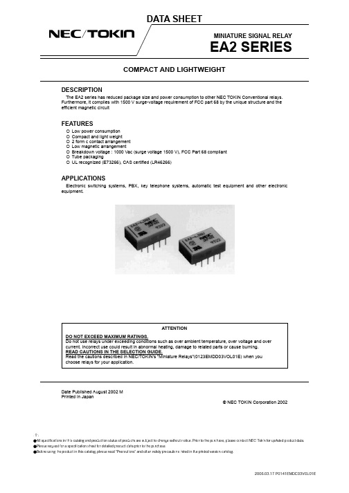
APPLICATIONS
Electronic switching systems, PBX, key telephone systems, automatic test equipment and other electronic equipment.
ATTENTION DO NOT EXCEED MAXIMUM RATINGS. Do not use relays under exceeding conditions such as over ambient temperature, over voltage and over current. Incorrect use could result in abnormal heating, damage to related parts or cause burning. READ CAUTIONS IN THE SELECTION GUIDE. Read the cautions described in NEC/TOKIN's "Miniature Relays"(0123EMDD03VOL01E) when you choose relays for your application.
Standard type
① ② ③ ④ ⑤
Part number Manufacturer Country of origin Date code Index mark of relay direction (pin No.1, 10) ⑥ UL, CSA Marking
UL recognized, CSA certified type
PIN CONFIGURATIONS
2
EA2 SERIES
美孚黑霸王产品介绍

优点和特性:
■ 可有效地防止因烟炱引起的机油变稠、机油堵塞和发动机磨损, 令发动机始终顺畅运作。 ■ 有助于延长发动机换油周期。 ■ 有效节省燃油消耗量。 ■ 是混合车队的理想之选。
© 2010 埃克森美孚公司
4
美孚黑霸王发动机油
美孚黑霸王特级15W-40 Mobil Delvac Super 1400 15W-40
有助于发动机在寒冷情况下容易起动。
分类和认可:
适用于以下要求及标准: ■ 美国石油协会API CG-4/CF-4/SJ。 ■ 欧洲汽车制造商协会ACEA E2,奔驰MB228.1. 曼MAN 271及沃尔沃Volvo VDS质量的要求。
优点和特性:
■ 有效防止机油变稠及防止高温积炭产生。 ■ 与单级机油相比可有效降低耗油量。 ■ 杰出高温/高剪力下的粘度稳定性, 有效防止气缸套抛光及拉缸。
© 2010 埃克森美孚公司
6
美孚传动系统润滑油
极低温及 延长换油期应用
-40oC以上 同步手动变速箱 API GL-4 驱动桥, 非同步手动变速箱 API GL-5 美孚黑霸王合成齿轮油 75W-90
低温~中等温度应用
-26oC ~ +40oC(80W-90) -12oC ~ +40oC(85W-90) -30oC ~ +40oC(80W-140, ATF) 美孚车用齿轮油 GX 80W-90
美孚黑霸王复合式粘度齿轮油 80W-90/85W-140 Mobil Delvac Gear Oil 80W-90/85W-140
是为要求满足极压及冲击负荷条件的重负荷尾 轴和后桥而专门配制的高品质齿轮润滑油。 性能卓越,适用于各种车辆及工程机械,同时 适用于准双曲面齿轮工况,满足高转速/冲击 负荷,高转速/低扭矩或低转速/高扭矩操作条 件的重负荷车辆及工业设备的应用。 分类和认可:
- 1、下载文档前请自行甄别文档内容的完整性,平台不提供额外的编辑、内容补充、找答案等附加服务。
- 2、"仅部分预览"的文档,不可在线预览部分如存在完整性等问题,可反馈申请退款(可完整预览的文档不适用该条件!)。
- 3、如文档侵犯您的权益,请联系客服反馈,我们会尽快为您处理(人工客服工作时间:9:00-18:30)。
32 31 30 29 28 27 26 25
INB0 VTB0 VREF-ACB0 /INB0 INB1 VTB1 VREF-ACB1 /INB1
SY58025UMI SY58025UMITR(2) SY58025UMG(3) SY58025UMGTR(2, 3)
1 2 3 4 5 6 7 8 9 10 11 12 13 14 15 16
QB /QB
AnyGate and Precision Edge are registered trademarks of Micrel, Inc. MicroLeadFrame and MLF are registered trademarks of Amkor Technology, Inc. M9999-020207 hbwhelp@ or (408) 955-1690
Precision Edge®
DESCRIPTION
The SY58025U features two ultra-fast, low jitter 2:1 differential muxes with a guaranteed maximum data or clock throughput of 10.7Gbps or 7GHz, respectively. The SY58025U differential inputs include a unique, internal termination design that allows access to the termination network through a VT pin. The device easily interfaces to different logic standards, both AC- and DCcoupled, without external resistor-bias and termination networks. The result is a clean, stub-free, low jitter interface solution. The differential CML output is optimized for 50Ω environments with internal 50Ω source termination and a 400mV output swing. The SY58025U operates from a 2.5V or 3.3V supply and is guaranteed over the full industrial temperature range (–40°C to +85°C). The SY58025U is part of Micrel’s Precision Edge® product family. All support documentation can be found on Micrel’s web site at .
Package Marking SY58025U SY58025U SY58025Uwith Pb-Free bar-line indicator SY58025U with Pb-Free bar-line indicator
Lead Finish Sn-Pb Sn-Pb Pb-Free NiPdAu Pb-Free NiPdAu
s Two independent differential 2:1 multiplexers s Guaranteed AC performance over temperature and voltage: • DC-to >10.7Gbps data rate throughput • <290ps IN-to-Out tpd • <70ps tr / tf times s Unique, patent-pending input isolation design minimizes crosstalk s Ultra-low jitter design: • <1psRMS random jitter • <10psPP deterministic jitter • <10psPP total jitter (clock) • <0.7psRMS crosstalk-induced jitter s Unique, patent-pending 50Ω input termination and VT pin accepts DC-coupled and AC-coupled inputs (CML, LVDS, PECL) s Typical 400mV CML output swing (RL = 50Ω) s Internal 50Ω input termination s Power supply 2.5V ±5% or 3.3V ±10% s –40°C to +85°C temperature range s Available in 32-pin (5mm × 5mm) MLF® package
24 23 22 21 20 19 18 17
32-Pin MLF® (MLF-32)
Notes: 1. Contact factory for die availability. Dice are guaranteed at TA = 25°C, DC electricals only. 2. Tape and Reel. 3. Pb-Free package recommended for new designs.
INA0 50Ω VTA0 50Ω /INA0 VREF-ACA0 INA1 50Ω VTA1 50Ω /INA1 VREF-ACA1 SELA (TTL/CMOS) 1 S MUX A 0 INB0 50Ω VTB0 50Ω 0
QA /QA
/INB0 VREF-ACB0 INB1 50Ω VTB1 50Ω /INB1 VREF-ACB1 SELB (TTL/CMOS) 1 S MUX B
元器件交易网
Micrel, Inc.
Precision Edge ULTRA PRECISION DUAL 2:1 CML SY58025U MUX WITH INTERNAL I/O TERMINATION
Precision Edge® SY58025U ®
FEATURES
Rev.: C Amendment: /0
1
Issue Date: FebruLeabharlann ry 2007元器件交易网
Micrel, Inc.
Precision Edge® SY58025U
PACKAGE/ORDERING INFORMATION
INA1 VREF-ACA1 VTA1 INA1 /INA0 VREF-ACA0 VTA0 INA0
APPLICATIONS
s s s s Data communication systems All SONET OC3-OC-768 applications All Fibre Channel applications All GigE applications
FUNCTIONAL BLOCK DIAGRAM
Ordering Information(1)
Part Number
GND VCC QA /QA VCC NC SELA VCC
Package Type MLF-32 MLF-32 MLF-32 MLF-32
Operating Range Industrial Industrial Industrial Industrial
PIN DESCRIPTION
Pin Number 25, 28, 29, 32, 1, 4, 5, 8 Pin Name INA0, /INA0, INA1, /INA1, INB0, /INB0, INB1, /INB1 Pin Function Differential Inputs: These input pairs are the differential signal inputs to the device. Inputs accept AC- or DC-coupled differential signals as small as 100mV. Each pin of a pair internally terminates to a VT pin through 50Ω. Note that these inputs will default to an indeterminate state if left open. Unused differential input pairs can be terminated by connecting one input to VCC and the complementary input to GND through a 1kΩ resistor. The VT pin is to be left open in this configuration. Please refer to the “Input Interface Applications” section for more details. Input Termination Center-Tap: Each side of the differential input pair, terminates to a VT pin. Each VT pin provides a center-tap to a termination network for maximum interface flexibility. See “Input Interface Applications” section for more details. Bank A, Bank B Input Channel Select (TTL/CMOS): These TTL/CMOS-compatible inputs select the inputs to the multiplexers. These inputs are internally connected to a 25kΩ pull-up resistor and will default to a logic HIGH state if left open. Input switching threshold is VCC/2. Reference Output Voltage: These outputs bias to VCC –1.2V. Connect to the VT pin when AC-coupling the data inputs. Bypass with 0.01µF low ESR capacitor to VCC. Maximum current source or sink is 0.5mA. See “Input Interface Applications” section. Positive Power Supply: Bypass with 0.1µF0.01µF low ESR capacitors. Differential CML Outputs: MUX A and MUX B selected CML outputs. See “Output Interface Applications” section for termination. Refer to the “Truth Table” for logic operation. Ground: Ground pin and exposed pad must be connected to the same ground plane. Not connected.
