HP EVA安装指南
HP StorageWorks EVA4x00 6x00 8x00 M5314 驱动器套式安装指南说
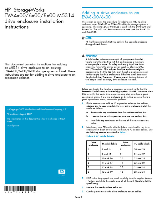
HP StorageWorksEVA4x00/6x00/8x00M5314 drive enclosure installation instructionsThis document contains instructions for addingan M5314drive enclosure to an existingEVA4x00/6x00/8x00storage system cabinet.These instructions are not for adding a drive enclosure to an expansion cabinet.20072007*5697-6937*Adding a drive enclosure to anEVA8x00/6x00This section contains the procedure for adding an M5314drive enclosure to an EVA8x00or EVA6x00while the storage system is operating.The M5314A or M5314B is used with the EVA8000and EVA6000.The M5314C drive enclosure is used with the EVA8100 andEVA6100.HP highly recommends that you perform this upgrade procedureduring off-peakhours.A fully loaded drive enclosure with all components installedweighs more than29.5kg(65lb.)and requires a minimumof two people to move.To safely and easily install the driveenclosure,remove the drives,power supplies,blowers,EMU,and I/O modules.This reduces the drive enclosure weight toapproximately11.0kg(24lb.).Even though a single person canlift this weight,the drive enclosure is difficult to install because ofthe physical size.Therefore,HP recommends that a minimum oftwo people install an empty drive enclosure in a rack.Before you begin this hardware upgrade,you must verify that the Enterprise Virtual Array is functioning e HP Command View EVA to verify that each drive enclosure and disk drive has a good operational status.If a drive enclosure or disk drive does not have a good operational status,correct the problem.1.If it is necessary to add an ID expansion cable to the cabinetaddress bus to accommodate the new drive enclosure,install the cable as follows:a.Remove the top terminator from the cabinet address bus.b.Connect the new ID expansion cable to the address bus.c.Install the top terminator at the end of the new expansioncable.bel each new FC cable with the labels contained in the driveenclosure kit.Each drive enclosure has two FC copper e the labeling scheme described in Table1.Table1FC cable labelsDriveenclosure FC cable labelsDriveenclosure FC cable labels 18and14820and2629and15921and27310and161022and28411and171123and29512and181224and30613and191325and313.If FC cable loop spools are used,carefully turn the captive fastener1/4turn and slide the cable loop off of the rail.Carefully,let the spool hang.4.Remove the nearby velcro cable ties.5.Cut the plastic ties on the drive enclosure power cables.6.Install the drive enclosure snap-in rail kit(part number302465-001).7.Install the drive enclosure into the rack.8.Insert and seat all disk drives and other components into the driveenclosure,but do not connect the cables.9.Connect the AC power to the drive enclosure and do the following:a.Wait for all FC disk drives to spinup.Thefirst drive in the drive enclosure might have the orangeDrive Failure icon lit.This is expected behavior.b.Check the EMU alphanumeric display for errors.See Figure1.Resolve any errors.CXO7373A1.Alphanumeric display2.Function select3.Display group selectFigure1EMU alphanumeric display and controlsc.Verify that the EMU displays00,indicating that the driveenclosure is not connected to the enclosure address bus.d.Verify that the fan LEDs are on and steady.See Figure2.Figure2Enclosure operational status indicationse.On both I/O modules,verify that the Power status indicatoris on and steady.Verify that both port status indicators areoff.See Figure3.f.Resolve any problems before proceeding to the next step.1.Upper port2.Power3.Lower portFigure3I/O module status indicators10.Check the operational status of the FC loops.a.On the controller,verify that the A-side and B-side device portindicators are on and steady.b.Resolve any problems before proceeding to the next step.11.Remove the GBICs from the required ports on the A and B loopswitches.ing a copper FC cable,connect I/O module A to the appropriateA-side loop switch.The A-side of the rack is the right side of the rack,when viewed from the rear.See Figure4and refer to Table2 and Table3to determine which cables and port connections to use.•On an EVA8x00,the location of the drive enclosure in the rack determines the loop switch it connects to.Drive enclosuresmounted in the lower half of the rack(enclosures1through6)connect to loops1A and1B.Drive enclosures mounted in theupper half of the rack(enclosures8through13)connect toloops2A and2B.•An EVA6x00includes a single set of loop switches and all drive enclosures are connected to loops1A and1B.a.Plug the FC cable into the correct port on the A-side loopswitch.b.Route the copper cable through the appropriate cablemanagement arm and radial clip.Do not route the coppercables throughflumes that containfiber optic cables.Instead,route the copper cables through vacantflumes.When you are adding the copper cables to the rack,handlethefiber optic cables with care.If you are not careful,youcan damage thefiber optic cables.c.Coil the excess copper cable and secure the cable behindthe rail with cable ties.d.Plug the cable into I/O module A of the drive enclosure.1.Loop2A 3.Loop1B2.Loop1A 4.Loop2BFigure4Loop locations in the Enterprise rack Table2FC cable connections for I/O module A,loop1ADrive enclosureI/OmoduleFC cable FC loopswitchFC loopswitchport1A81A122A91A103A101A84A111A65A121A46A131A2Table3FC cable connections for I/O module A,loop2ADrive enclosureI/OmoduleFC cable FC loopswitchFC loopswitchport8A202A1 9A212A3 10A222A5 11A232A7 12A242A9 13A252A1113.Verify that the FC connection is operating correctly.a.Verify that the green SFP Status LED on the FC loop switch ison and steady and the Port bypassed LED is off.See Figure5.b.Verify that the corresponding port status indicator on I/Omodule A is on and steady.c.Verify that the corresponding A device port on the controlleris on and steady.The orange Drive Failure icon on thefirst drive in the driveenclosure is turned off.d.Verify thatthe upgraded configuration is working properly, using HP Command View EVA.•Verify that the added drive enclosure has a good status.•Verify that each disk drive in the added drive enclosure has a good status.e.Resolve any problems before proceeding to the next step.FrontBezelCXO7884A1.SFP status 4.Over temp2.Port bypassed 5.Power3.POST fault 6.Loop operationalFigure5FC loop switch status indicatorsing a copper FC cable,connect I/O module B to the appropriateB-side loop switch.The B-side of the rack is the left side of the rack when viewed from the rear.See Table4and Table5to determine which cables and port connections to use.Make sure you are connecting the drive enclosure tocorresponding loop switches.If you used loop switch1A for portA,then you must use loop switch1B.If you used loop switch2A, then you must use loop switch2B.If you fail to connect the driveenclosure to corresponding loop switches,you can make thedata in the other drive enclosures inaccessible.a.Plug the FC cable into the correct port on the B-side loopswitch.b.Route the copper cable through the appropriate cablemanagement arm and radial clip.Do not route the coppercables throughflumes that containfiber optic cables.Instead,route the copper cables through vacantflumes.When you are adding the copper cables to the rack,handlethefiber optic cables with care.If you are not careful,youcan damage thefiber optic cables.c.Coil the excess copper cable and secure the cable behindthe rail with cable ties.d.Plug the cable into I/O module B of the drive enclosure.Table 4FC cable connections for I/O module B,loop 1B Drive enclosure I/O moduleFC cableFC loop switch FC loop switch port 1B 141B 22B 151B 43B 161B 64B 171B 85B 181B 106B 191B12Table 5FC cable connections for I/O module B,loop 2B Drive enclosure I/O moduleFC CcableFC loop switch FC loop switch port 8B 262B 119B 272B 910B 282B 711B 292B 512B 302B 313B 312B115.Verify that the FC connection is operating correctly.a.Verify that the green SFP Status LED on the FC loopswitch ison and steady and the Port bypassed LED is off.b.Verify that the corresponding port status indicator on I/Omodule B is on and steady.c.Verify that the corresponding B device port on the controller is on and steady.d.Resolve any problems before proceeding to the next step.16.Connect the newly added drive enclosure to the enclosure addressbus.See Figure 6for the enclosure numbering.•CAB address ports 8and 14share a common address.When adding a drive enclosure to loop 2on an EVA8x00,make sure drive enclosures are connected to either port 8or port 14.You can use one or the other but not ing both of these ports on the same loop makes it dif ficult to analyze disk problems because the disks in the drive enclosure connected to ports 8and 14appear to have the same addresses.•When adding a drive enclosure to an EVA6x00,do not use address port 7for the enclosure.Address port 7does not receive a hard AL-PA range.a.Verify that the EMU displays a unique enclosure number.b.Verify that the EMUs on the other drive enclosures continue todisplay valid enclosure numbers.c.Wait 15minutes.d.Verify that HP Command View EVA displays the recentlyadded drive enclosure under the Rack element in theNavigation pane.It should no longer be in the Unmappable Hardware folder.e.Verify that the upgraded con figuration is working properly,using HP Command View EVA.•Verify that the added drive enclosure has a good status.•Verify that each disk drive in the added drive enclosurehas good status.0046a-2Figure 6Enclosure numbering17.Repeat the above steps to add each drive e nylon ties to secure the copper FC cables.19.In HP Command View EVA,con figure the additional storagecapacity.See the HP StorageWorks 4x00/6x00/8x00Enterprise Virtual Array user guide and the EVA Best Practices white paper for information on using the new disk capacity.Adding a drive enclosure to an EVA4x00This section contains the procedure for adding an M5314drive enclosure to an EVA4x00while the storage system is operating.The M5314A or M5314B is used with the EVA4000.The M5314C drive enclosure is used with the EVA4100.HP highly recommends that you perform this upgrade procedure during off-peak hours.A fully loaded drive enclosure with all components installedweighs more than29.5kg(65lb.)and requires a minimumof two people to move.To safely and easily install the driveenclosure,remove the drives,power supplies,blowers,EMU,and I/O modules.This reduces the drive enclosure weight toapproximately11.0kg(24lb.).Even though a single person canlift this weight,the drive enclosure is difficult to install because ofthe physical size.Therefore,HP recommends that a minimum oftwo people install an empty drive enclosure in a rack.Before you begin this hardware upgrade,you must verify that the Enterprise Virtual Array is functioning e HP Command View EVA to verify that each drive enclosure and disk drive has a good operational status.If a drive enclosure or disk drive does not have a good operational status,correct the problem.bel each new FC cable with the labels contained in the driveenclosure kit.Each drive enclosure has two FC copper cables. 2.If FC cable loop spools are used,carefully turn the captive fastener1/4turn and slide the cable loop off of the rail.Carefully,let the spool hang.3.Remove the nearby velcro cable ties.4.Cut the plastic ties on the drive enclosure power cables.5.Install the snap-in rail kit(part number302465-001).6.Install the drive enclosure into the rack.7.Insert and seat all drives and other components into the driveenclosure,but do not connect the cables.8.Connect the AC power to the drive enclosure and do the following.a.Wait for all FC disk drives to spinup.Thefirst drive in the drive enclosure might have the orangeDrive Failure icon lit.This is expected behavior.b.Check the EMU alphanumeric display for errors.See Figure1.Resolve any errors.c.Verify that the EMU displays00,indicating that the driveenclosure is not connected to the enclosure address bus.d.Verify that the fan LEDs are on and steady.See Figure2.e.On both I/O modules,verify that the Power status indicatoris on and steady.Verify that both port status indicators areoff.See Figure3.f.Resolve any problems before proceeding to the next step.9.Check the operational status of the FC loops.a.On the controller,verify that the A-side and B-side device portindicators are on and steady.b.Resolve any problems before proceeding to the nextstep.As long as one I/O loop(1A or1B)is operational,storagesystem operation will not be interrupted.Make sure youdisconnect only one loop at a time.Make sure a loop isoperational before disconnecting the other loop.10.Connect the new drive enclosure to I/O loop1A:a.Disconnect the FC cable from device port DP1A on the upperstorage system controller.b.Connect this cable to the lower port on I/O module A of thenew drive enclosure.c.Connect a FC cable from the upper port on I/O module A ofthe new drive enclosure to device port DP1A on the upperstorage system controller.11.Verify that loop1A is operating correctly.a.Verify that the upper and lower port LEDs on I/O module Aare on and steady.b.Verify that device port DP1A on the controller is on andsteady.The orange Drive Failure icon on thefirst drive in the driveenclosure is turned off.c.Verify that the upgraded configuration is working properly,using HP Command View EVA.•Verify that the added drive enclosure has a good status.•Verify that each disk drive in the added drive enclosure has a good status.d.Resolve any problems before proceeding to the next step.12.Connect the new drive enclosure to I/O loop1B:a.Disconnect the FC cable from device port DP1B on the lowerstorage system controller.b.Connect this cable to the lower port on I/O module B of thenew drive enclosure.c.Connect a FC cable from the upper port on I/O module Bof the new drive enclosure to device port DP1B on the lowerstorage system controller.13.Verify that loop1B is operating correctly.a.Verify that the upper and lower port LEDs on I/O module Bare on and steady.b.Verify that device port DP1B on the controller is on and steady.c.Resolve any problems before proceeding to the next step.14.Connect the newly added drive enclosure to the enclosure addressbus.See Figure6for the enclosure numbering.a.Verify that the EMU displays a unique enclosure number.b.Verify that the EMUs on the other drive enclosures continue todisplay valid enclosure numbers.c.Wait15minutes.d.Verify that HP Command View EVA displays the recentlyadded drive enclosure under the Rack element in theNavigation pane.It should no longer be in the UnmappableHardware folder.e.Verify that the upgraded configuration is working properly,using HP Command View EVA.•Verify that the added drive enclosure has a good status.•Verify that each disk drive in the added drive enclosure has good status.15.Repeat the preceding steps to add additional drive enclosures.16.In HP Command View EVA,configure the additional storagecapacity.See the HP StorageWorks4x00/6x00/8x00Enterprise Virtual Array user guide and the EVA Best Practices white paper for information on using the new disk capacity.。
HP StorageWorks Continuous Access EVA实现指南说明书
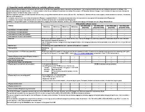
Asynchronous write mode (enhanced)
•
•
•
•
•
•
Asynchronous write mode (standard)
•
•
Auto suspend on full copy (set at creation)
•
•
•
•
•
Auto suspend on links down (set at creation)
DR group log file size (user configurable)3
•
•
•
•
•
•
•
•
•
•
2x the combined size of DR group
members (cannot be changed)
Smaller of: – 2,047.99 GB maximum virtual disk size – Remaining space in disk group in which the DR group log resides – The sum of the sizes of the members within the DR group2
•
•
•
•1
•1
100 GB (Synchronous and Asynchronous)
Maximum log file size within these parameters: – 2,047.99 GB maximum virtual disk size – Greater than 136 MB4, 5 – Less than or equal to the available capacity in the source log disk group. The capacity selected must also be available in the destination log disk group.
HP EVA5000盘阵和MSL6030磁带库部署实施图解

目录1.EV A5000盘阵安装过程 (2)硬件安装步骤 (2)硬件安装的详细要求 (2)安装前准备工作 (2)现场货物清点 (3)设备就位,连线和加电测试 (3)需要安装的软件和配置的详细步骤 (3)软件安装步骤 (4)升级Command View EV A软件 (4)EVA5000磁盘阵列设置 (4)2.FC SWITCH 16B的设置 (26)3.MSL6030磁带库的安装 (27)磁带库安装上架 (27)磁带库默认口令 (30)通过Telnet管理磁带库 (31)通过web界面管理磁带库 (39)使用Web测试磁带库 (45)4.硬件安装后的检验 (53)5.硬件安装注意事项 (54)1.EVA5000盘阵安装过程硬件安装步骤硬件安装的详细要求1、EVA5000磁盘阵列的硬盘安装。
2、升级EVA 5000磁盘阵列firmware或升级管理端管理软件。
3、磁带库磁带的安装,磁带条形码的粘贴,清洗带的安装。
4、SAN switch 2/16的安装。
(注意:JBOD盘箱DS2405暂时不连接在EV A5000控制盘箱上,EVA5000连线图如下:)下图为实景安装前准备工作1) 安装前应和用户联系,了解用户场地状况(参照场地准备通知书)➢用户电源准备情况➢用户的网线,网络设备是否就序➢用户是否备有诊断电话线➢机房是否满足HP EVA5000和HP MSL6030设备对安装空间的要求。
2) 工程师需带齐所有的Installaction Kit➢安装手册➢装箱单(Packing list)➢安装报告➢安装工具➢笔记本电脑➢标签纸(Label)➢串口线现场货物清点开箱进行货物清点根据HP Packing List 对箱数进行清点。
在阵列带库加电以后,HP、太极华青和用户三方对机械手、磁带驱动器、磁盘阵列高速缓存、内置硬盘容量、光纤交换机SFP数量,以及firmware版本行核对。
*请工程师务必仔细检查货物的外包装有无损坏,倾斜标志显示是否正常,有问题请及时与HP项目组联系。
HPE OneView安装教程说明书
HPE course number Course length Delivery modeCourse data sheetAccess periodWhy HPE Education Services?•Comprehensive worldwide HPE technical, IT industry and personal developmenttraining•Training and certification preparationfor ITIL®, Security, VMware®, Linux,Microsoft and more•Innovative training options that matchindividual learning styles •Anytime, anywhere remote learning viaHPE Digital Learner subscriptions •Verifiable digital badges for proof oftraining, skill recognition and careerdevelopment•Simplified purchase options withHPE Training Credits Installing HPE OneView,Rev. 21.41H9TS6AAET his eLearning training course teaches you how to install HPE OneView. The course includes self-paced, hands-on lab exercises, You need to open the eLearning course to download the Lab Guide and the Environment Guide. There are three options for the host—VMware ESXi™, Windows Server Hyper-V, and RHEL KVM. You can choose to install HPE OneView on any, or all, of these options.AudienceSystem, networking, and storage architectsintegrating HPE OneView into theirdatacenters, and the administrators whomanage and monitor an HPE environmentor anticipate the implementation of HPEOneViewPrerequisitesBasic system and network administrationknowledge and skillsCourse objectivesAfter completing this course, you will be ableto:•Deploy the HPE OneView appliance on anyof the three supported hypervisor hosts(VMware ESXi, Microsoft Hyper-V, or KVM)•Configure HPE OneView on first access,either manually or using the Guided Setupfeature•Upload the HPE SPP to the firmwarerepository•Add an HPE OneView Advanced license•Back up the HPE OneView applianceH9TS6AAE4 hours eLearning Unlimited access for one year from the date of purchaseModule 1: Introduction to HPE OneView•Module overview•HPE OneView features•HPE OneView deliverables•Preparing HPE OneView for deployment•Key takeaways•Learning checkModule 2: Deploying HPE OneView on aHypervisor Host•Module overview•Deploying the HPE OneView appliance on a VMware ESXi host•Deploying the HPE OneView appliance on a Microsoft Hyper-Vhost•Deploying the HPE OneView appliance on a KVM host•Key takeaways•Learning check Lab 1: Deploying HPE OneView on a Hypervisor Host •Deploying HPE OneView on a VMware ESXi host •Deploying HPE OneView on a Windows Server Hyper-V host •Deploying HPE OneView on a RHEL KVM hostModule 3: Configuring HPE OneView onFirst Access•Module overview•First time setup•Application support•Initial login•Initial network configuration for the appliance•IPv6 support and configuration•Applying network settings•Appliance is ready to use•Try-it: first-time setup•Key takeaways•Learning check Lab 2: Accessing HPE OneView for the First Time •Set up the HPE OneView appliance for the first timeModule 4: Setting Up HPE OneViewOptions•Module overview•Configuring HPE OneView using Guided Setup•Configuring HPE OneView manually•Firmware management•Adding an HPE OneView Advanced license•Try it: Adding an HPE OneView Advanced license•Backing up an HPE OneView appliance•Key takeaways•Learning check Lab 3: Configuring HPE OneView and Creating a Backup •Access HPE OneView through a supported web browser •Navigate through the HPE OneView GUI•Adjust time and locale•Upload Service Pack for ProLiant bundle•Add the HPE OneView Advanced license•Create an HPE OneView configuration backupModule 5: Course Resources Detailed course outlineLearn more at/ww/learnconvergedsystemsFollow us:© Copyright 2021 Hewlett Packard Enterprise Development LP. The information contained herein is subject to change withoutnotice. The only warranties for Hewlett Packard Enterprise products and services are set forth in the express warranty statementsaccompanying such products and services. Nothing herein should be construed as constituting an additional warranty.Hewlett Packard Enterprise shall not be liable for technical or editorial errors or omissions contained herein.All other third-party marks are property of their respective owners.H9TS6AAE, 21.41, December 2021。
HP StorageWorks EVA6400 8400 安装环境常见情况下的串联图说明书
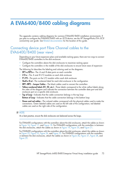
A EVA6400/8400 cabling diagramsThis appendix contains cabling diagrams for common EVA6400/8400 installation environments. Ifyou plan to configure the EVA6400/8400 with an iSCSI device, see the HP StorageWorks EVA iSCSI connectivity user guide. See Related documentation for the location of this guide. Connecting device port Fibre Channel cables to theEVA6400/8400 (rear view)Depending on your future expansion plans and available racking space, there are two ways to connect EVA6400/8400 controllers to the disk enclosure:•Configure the controllers above the disk enclosures to maximize racking space•Configure the controllers in the middle of the disk enclosures to ensure future ease of expansionThe following list describes the labeling and coloring used on the diagrams:•DP1-x/DP2-x—The -A and -B data ports on each controller•I/O-x—The -A and -B I/O modules on each disk enclosure•P1/P2—The ports on the I/O module within each disk enclosure•Shelf-x (S-x)—The numbered label for each disk enclosure in the configuration•MP1–MP2 – Jumper Cables—The black cables used to connect the controllers•Yellow numbered labels (01, 02, etc.)—These labels correspond to the white callout labels along the sides of the diagram and indicate the connection between the controller data port and diskenclosure port on a specific disk enclosure.•Top of Loop—Indicates that the cable connection belongs in the top loopBottom of Loop—Indicates that the cable connection belongs in the bottom loop•Green and red cables—The colored cables correspond with the physical cables used to make the connections. Green labeled cables are used on the left side of the configuration; red labeledcables are used on the right side of the configuration.NOTE:As a best practice, ensure the disk enclosures are balanced across the loops.For EVA6400 configurations with the controllers above the disk enclosures, attach the cables as shown in Figure 16, Figure 17, and Figure 18. For EVA6400 configurations with the controllers in betweenthe disk enclosures, attach the cables as shown in Figure 19, Figure 20, and Figure 21.For EVA8400 configurations with the controllers above the disk enclosures, attach the cables as shown in Figure 22, Figure 23, Figure 24, and Figure 25. For EVA8400 configurations with the controllersin between the disk enclosures, attach the cables as shown in Figure 26, Figure 27, Figure 28, andFigure 29.HP StorageWorks 6400/8400 Enterprise Virtual Array installation guide73Connecting EVA6400 controllers above the disk enclosures (2C6D) Figure 16 shows the connections to loop 1 between the EVA6400 controllers and disk enclosures 1, 2, and 3 (S-1, S-2, and S-3).Figure 16 Fibre Channel cabling for the EVA6400 loop 1 connections (rear view, top-mountedcontrollers)74EVA6400/8400 cabling diagramsFigure 17 shows the connections to loop 2 between the EVA6400 controllers and disk enclosures 4, 5, and 6 (S-4, S-5, S-6).Figure 17 Fibre Channel cabling for the EVA6400 loop 2 connections (rear view, top-mounted controllers)HP StorageWorks 6400/8400 Enterprise Virtual Array installation guide75Figure 18 shows a fully cabled EVA6400 system with two controllers and six disk enclosures (2C6D).Figure 18 Complete Fibre Channel cabling for the EVA6400 2C6D (rear view, top-mounted controller) 76EVA6400/8400 cabling diagramsConnecting EVA6400 controllers between the disk enclosures (2C18D) Figure 19 shows the connections to loop 1 between the EVA6400 controllers and disk enclosures 1through 9.Figure 19 Fibre Channel cabling for the EVA6400 loop 1 connections (rear view, mid-mountedcontrollers)HP StorageWorks 6400/8400 Enterprise Virtual Array installation guide77Figure 20 shows the connections to loop 2 between the EVA6400 controllers and disk enclosures 10 through 18.Figure 20 Fibre Channel cabling for the EVA6400 loop 2 connections (rear view, mid-mounted controllers)78EVA6400/8400 cabling diagramsFigure 21 shows a fully cabled EVA6400 system with 2 controllers and 18 disk enclosures (2C18D).Figure 21 Complete Fibre Channel cabling for EVA6400 2C18D (rear-view, mid-mounted)HP StorageWorks 6400/8400 Enterprise Virtual Array installation guide79。
HPEVA6000详细配置基础教程

HPEVA6000详细配置基础教程EVA连接拓扑⽰意图如下:EVA配置教程如下:1、EVA系统的开机和关机顺序EVA作为企业的核⼼数据存储系统,如何正确的开机和关机对数据安全有着很⼤的影响。
在⽇常维护中,请务必按照正确顺序进⾏开关机。
1.1 EVA系统的开机顺序正确的开机顺序为:1、开机柜总电源;2、开光纤交换机电源,开EVA 机柜电源(此时硬盘柜⾃动加电);3、启动SMA;4、等待10 分钟待光纤交换机和硬盘柜状态正常后开控制卡电源;5、等待3 分钟待控制卡状态稳定后开主机电源,启动进⼊操作系统6、起集群服务及应⽤;1.2、EVA系统的关机顺序正确的关机顺序为:1、停集群服务和节点2、shutdown 服务器;3、通过sma关闭eva的控制卡;4、关闭eva控制卡后的开关;5、关闭SMA;6、关闭SAN SWITCH;7、关闭EVA机柜电源;关闭控制卡如下图:2、配置过程如下2.1配置管理界⾯地址栏输⼊https://192.168.0.1:2373如下图进⼊登陆界⾯,如下图输⼊登陆名admin密码为空进⼊管理界⾯选择configure controlledr host ports 查看连接端⼝状况:在第⼀个控制模块controller1 中点击less details 查看连接属性topology (如果是服务器直连控制器选择Dirext;如果是连接光交换机那么选择fabric)选择相应选项后点save changes保存变更。
同样选择第⼆个控制模块进⾏更改。
(注意:更改完成后需要重启控制器⽣效)更改完成后点击launch HP P6000 command View选项点击launch HP P6000 command View按钮进⼊存储管理界⾯。
2.2、初始化 EVA点击初始化图标,eva 将初始化,初始化过程中要求输⼊存储的名称,该名称将在⾯板上显⽰。
初始化会导致所有的数据都会丢失!进⼊以下界⾯:点击settings进⼊初始化界⾯初始化全过程如下图:点击initialize:设置名称以及硬盘数量最⼤为12,以及系统时间确定并初始化完成。
HP EVA4400实施文档
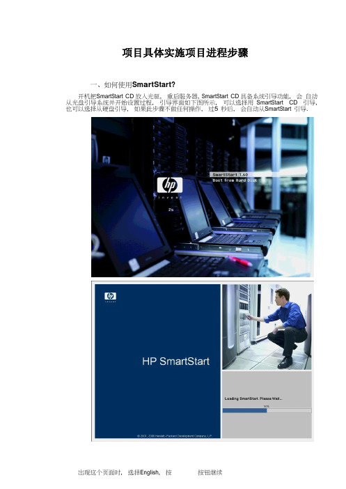
项目具体实施项目进程步骤一、如何使用 S m ar tStart ?开机,把 S mart S t ar t CD 放入光驱, 重启服务器, S m ar t S ta r t CD 具备系统引导功能, 会 自动从光盘引导系统并开始设置过程, 引导界面如下图所示, 可以选择用 Smart S t ar t CD 引导, 也可以选择从硬盘引导, 如果此步骤不做任何操作, 过 5 秒后, 会自动从 S mart S t ar t 引导.出现这个页面时, 按按钮接受使用协议继续:接下来就进行SmartStart的具体操作了.二、安装操作系统本章将介绍S mart S t ar t CD的主要功能:在上一章接受协议后, 将出现下图所示画面, 画面下方有3个按钮, 其中: 点击按钮可以部署服务器,按钮可以对服务器进行配置, 检测等操作1. 在上图中点击,出现如下图画面。
2. 点击右面的按钮,如果出现如下界面,表示内部硬盘的RAID1 出厂,则直接跳到步骤()。
已经做好(默认是这样)3. 如果出现的界面如下所示,则说明本地硬盘RAID没有做,这时候点击Create Arra y按钮创建A rra y4. 点击c re a te arra y后出现如下界面,选择s e l ect All 选项后点击O K 按钮。
5. 点击O K 后出现如下界面:然后点击右上角的c re a te Lo g i c al D r i ve按钮钮。
7. 在下面界面内直接点击S mart S t ar t Home按钮后回到主界面。
8. 在主界面中点击按钮,出现下图所示画面, 其中画面左侧的3个按钮可分别实现:⓿: 重启服务器并进入R B S U(R OM B a se d S etu p Ut i l i ty), 同自检时按[F9];Arra y), 同自检到S martA rra y阵列卡时按[F8];⓿: 启动A CU(Arra y C o nf i g ur atio n Utility)图形化R AID配置工具在这里, 直接按按钮继续,业版, 按按钮继续:化为N TF S文件系统, 按按钮继续:方式(此处根据所购买的微软系统许可协议选择输入), 按按钮继续:按按钮继续:作, 并会自动弹出光盘, 要求放入操作系统光盘, 放入操作系统光盘后, 将自动完成整个安装过程, 此过程需要3~4 次重启.15. 安装重启后,系统最后阶段需要参与如下图:点击下一步.16. 如下图,系统提示输入使用者的用户名和单位,点击下一步17〃输入计算机名和管理员密码,点击下一步18〃如下图,直接点击下一步,系统进行一会后会提示您输入工作组名字,这里输入W G(其它名字也可,因为后续需要升级到域),19、直接点击下一步,系统进行一会后会提示您输入工作组名字,这里输入W G(其它名字也可,因为后续需要升级到域),点击下一步,系统会自动完成后续安装,系统完成重启后会自动安装 H P 一些管理监控软件, 需要一段时间,请耐心等候。
EVA安装调试手册EVA安装调试手册EVA安装调试手册
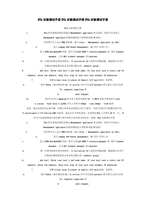
EVA安装调试手册EVA安装调试手册EVA安装调试手册EVA安装调试手册1. EVA的安装调试通常是通过Management Appliance来完成的,我们可以先接上ManagementAppliance的鼠标键盘进入系统来设置IP地址。
2. 在管理平台上运行WEB浏览器,输入http:// Management Appliance ip:2301/3. 进入compaq web-based management,输入用户名和口令。
4. 进入OPEN SAN MANAGER页面,展开左面SAN TREE中resource manager项,展开element manager ,点击HSV element manager,按launcher5. 第一次使用系统会要求初始化,按initialize,输入系统名和磁盘数,磁盘数以后也可以增加但最低要求是8块并做为默认组(default group).6. add host, Enter your host's LAN node name, If your host uses a static LAN IP address,enter the address. Skip this step if your host uses dynamic IP addresses.7. 设置vitual disk,选create vd family,选择raid级别,容量等。
8. 展开VD001(刚才做好的VD)选 active,其中可以选择present(要让那台主机可以看到),snapshot,snapclone等9. save changes10. 此时可以在已mapping的主机上找到分配的VD。
在HPUX系统中使用命令insf –e,ioscan–funC disk,在ALPHA平台上用命令hwmgr –scan,hwmgr –view找到这是一篇比较简单的安装步骤一些图片和术语说明我会写在手册里,当然不同的平台配置还要不同,如secure path以及和Veritas DMP比较等,我也会在手册里说明,总体感觉EVA上手要比XP快一点。
HP惠普EVA4400安装步骤最新
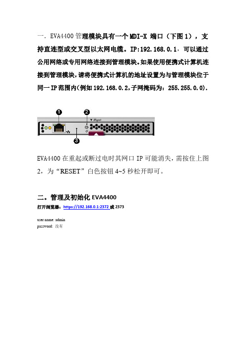
一.EVA4400管理模块具有一个MDI-X 端口(下图1),支持直连型或交叉型以太网电缆。
IP:192.168.0.1,可以通过公用网络或专用网络连接到管理模块。
如果使用便携式计算机连接到管理模块,请将便携式计算机的地址设置为与管理模块位于同一IP范围内(例如192.168.0.2,子网掩码为: 255.255.0.0).EVA4400在重起或断过电时其网口IP可能消失,需按住上图2,为“RESET”白色按钮4~5秒松开即可。
二。
管理及初始化EVA4400打开浏览器:https://192.168.0.1:2372或2373user name: adminpassword: 没有EVA”就到了上面的登录画面选初始化选项,在下图写存储柜的名字(随便起),和第一个磁盘组的盘数(至少8个)设定时间选热备区容量:single 表示留出2disk的空间做spare,double 表示留出4disk 空间做spare;如硬盘空间足够大,建议选择double,但至少选择single点“OK”和“FINISH”完成初始化,这里要等一段时间。
看到的是这样系统自己认出EVA4400的WWN号:5001-4380-025D-DC20记下来准备注册许可证。
磁盘组中盘越多性能越好,新加的盘会在“ungrouped disks”一栏里,鼠标拖进已有的盘组即可。
注册许可证后是这样,必须有容量许可证否则不能划分虚拟盘。
EVA 容量许可证网上注册后的范本:红字的就是许可证A copy of your license/password certificate(s) are displayed below foryour review.在:“HOSTS“下建立各主机的名字(随便起),操作系统类型和其HBA卡的WWPN号。
(这里每台机器只一个卡)这是建立各个虚盘大小和名字(随便起)这是建立虚盘与主机的映射关系在主机端验证映射的盘三.EV A4400支持与主机直连时需要如下更改:四.EV A4400 接线图如下:。
EVA 日常操作1

日常操作注意事项1、存储2、开关机顺序3、日常例行维护4、出现故障时如何寻求帮助一、存储阵列存储阵列HP EVA4400正面视图:最下为控制器盒(内置两个控制器),上为两个硬盘盒。
(后视图及连线)上为控制器盒 下为硬盘盒注意:所有从控制器设备端口A 引出的电缆都必须插入磁盘盒上的A I/O 模块。
所有从控制器设备端口B 引出的电缆都必须插入磁盘盒上的B I/O 模块。
三、开关机顺序开机顺序1、先开存储将电源插入存储的硬盘盒以及控制器盒电源借口处,硬盘盒会自动加电开机。
硬盘盒内的硬盘会自检。
等待只有最左上角硬盘亮黄灯时,再开启控制器电源开关。
存储完全启动完毕后,所有指示灯全部会变成绿色。
2、开主机将电源插入主机后部电源接口后,前面板电源开关按钮会变为橙色,此时可按电源按钮开机。
关机顺序1、先关闭主机2、关闭存储存储的管理地址为192.168.0.1在浏览器地址栏中输入https://192.168.0.1:2372可进入管理登录界面,用户名admin,密码为空。
(若不能正常显示图片,请调整浏览器安全设置)登录后界面如下:点击system optin(上图标红圈处)。
进入以下界面后,点击shutdown system然后选择power off,然后会出现两次确认,即可关闭eva。
点击确定按钮,完成关闭存储。
(硬盘盒和控制器盒会同时关闭)存储完全关闭后,前面板所有指示灯会变为橙色。
此时可断开所有电源。
切记:严禁在关闭控制器之前,先行拔除硬盘盒电源,否则可能引起数据丢失。
一定要通过管理界面来shutdown eva,直接拔电源会造成eva电池过度放电,从而导致eva再次加电之后数据无法读写。
四、日常例行维护4.2 存储部分:4.2.1在浏览器地址栏中输入https://192.168.0.1:2373可进入管理登录界面,用户名admin,密码为空。
点击Launch Command View EVA,进入如下界面:点击EVA4400―》hardware,展开菜单,可以看到eva的组成硬件,如控制器、硬盘架、硬盘等信息。
安装EVA4000简单步骤

HP-EVA4400安装2.安装HP存储的问题连接过程,通过带内管理,并把PC服务器的fc口和磁盘阵列通过光纤交换机连接起来,在pc服务器上安装管理软件,插入光碟StorageWorks EVA SmartStart CD安装过程如下: 可参照安装说明来做( HP_StorageWorks_EVA_4400_Installation_Video_WBT.EXE)( 如下是安装EVA SmartStart的步骤)Insert the StorageWorks EVA SmartStart CD into the host server’s CD-ROM or DVD-ROM drive.The CD should autoplay and show the Welcome screen and End User License Agreement (EULA).Note: If the “Required Software Missing” dialog box appears, follow the prompts to install the necessary supporting software and restart the server.After the server restarts, return to step 1 and re-insert the CD.Accept the EULA to continue.On the Welcome to HP EVA SmartStart screen, select Start NowSelect Configure as management server on the Select a Configuration Option screen. Review the configuration steps on the Configure Management Server Overview screen. Follow the prompts on the next several screens to check server LAN connections, and check and install any necessary drivers for the FC connections and HBAs.On the HP Command View EVA Check screen, click Next to begin installation of the Command View EVA software.Follow the prompts on the next several screens to install Command View EVA and ensure the Results screen displays Installation was successful in the information box. IMPORTANT! On the following screen, make a note of the Windows security group (HP Storage Admins) and Administrator account (hpadmin) to be created.Continue to the HP Command View EVA Security Setup screen, review the text, and enter the password you wish to use with Command View.Ensure the security setup was successful.If prompted, enter your Command View EVA password on the final HP Command View EVA Check screen and continue through the License Information screen.The HP EVA Storage Systems Initialization Check screen allows you to choose from two initialization options:The setup wizard automatically initializes your storage system and creates the disk groups,ORYou want to initialize your system and create disk groups manually using Command View EVA.IMPORTANT! If you need to control how disk groups are created on a storage system, do not use the wizard for initialization. Instead, use HP Command View EVA.To initialize storage using the wizard, click Next and follow the prompts and instructions on the next several screens.Ensure successful initialization on the Storage Systems Initialization Check Results page. Review the Summary and Next Step Options on the Configure Management Server Summary page.安装成功后,可以用这个软件来管理存储了.对存储划分vdisk来指派到机器之前,要激活存储的license.从随机带来的信封上找到HP存储的ordercode,在hp官方网站(https:///)上申请license,申请时要输入存储的HBA卡的WWN号码.要求把license发到制定的邮箱中把license拷贝下来,复制如下图的licensing 里的选项中EVA 4400了.注: 提交了有效license,才可以创建vdisk现在我们需要指定Virtual Disk folder,In the Navigation pane, expand the tree for the selected storage system and select Virtual Disks.In the Virtual Disks Folder Properties screen click Create Folder.In the Create a Folder screen enter a folder name and any comments, and click Finish.建立virtual diskIn the Navigation pane select the virtual disk folder you just created.Select Create Vdisk on the Vdisk Folder Properties screen.Note: The only entry actually required on the Create a Vdisk screen is the virtual disk size. The defaults can be accepted for all other attributes.In the Create a Vdisk screen, do the following:Enter the virtual disk name.Specify the desired virtual disk size in gigabytes (GB).Ensure the Default disk group is selected in the Disk Group dropdown box.Select the desired virtual disk redundancy level.Accept the defaults in the Advanced Settings section.Enter Comments if necessary.Click Create Vdisk to create the virtual disk.Create additional virtual disks as desired in the folder.In the Navigation pane select the virtual disk you just created.Review the Vdisk Properties screen for accuracy.建立host folderIn the Navigation pane, expand the tree for the selected storage system and select Hosts. Click Create Folder in the Host Folder Properties screen.In the Create a Folder screen enter the desired folder name and optional comments, and click Finish添加hostBefore you begin: Gather the following information about the host you wish to add:The host’s LAN nameThe WorldWide Name of at least on of the host’s FCA portsThe host’s operating systemThe host’s IP address (this parameter is optional)In the Navigation pane select the host folder you just created.Click Add Host in the Host Folder Properties screen.In the Add a Host screen, enter the host name and other parameters gathered previously, and click Add Host.Verify that the host has been added.给host添加对应的hba卡号On the Host Properties screen select the Ports tab, then select Add port.Select a WorldWide Name from the dropdown list on the Add a Host Port screen, then click Add port.Verify that your host is added in the Host Properties screen.把virtualdisk指派给hostIn the Navigation pane, select the virtual disk you want to present.Click the Presentation tab on the Vdisk Properties screen, enter the Preferred path/mode from the dropdown box if desired, then click Present.In the tree control displayed, select the host and click Present Vdisk.Verify your presentation by clicking the Presentation tab on the Vdisk Properties screen. 搞定收工。
HP EVA command view eva user guide
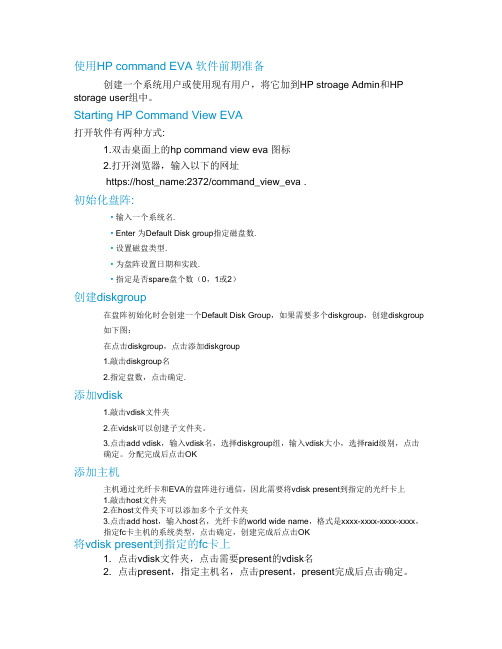
使用HP command EVA 软件前期准备创建一个系统用户或使用现有用户,将它加到HP stroage Admin和HP storage user组中。
Starting HP Command View EVA打开软件有两种方式:1.双击桌面上的hp command view eva 图标2.打开浏览器,输入以下的网址https://host_name:2372/command_view_eva .初始化盘阵:• 输入一个系统名.• Enter 为Default Disk group指定磁盘数.• 设置磁盘类型.• 为盘阵设置日期和实践.• 指定是否spare盘个数(0,1或2)创建diskgroup在盘阵初始化时会创建一个Default Disk Group,如果需要多个diskgroup,创建diskgroup 如下图:在点击diskgroup,点击添加diskgroup1.敲击diskgroup名2.指定盘数,点击确定.添加vdisk1.敲击vdisk文件夹2.在vidsk可以创建子文件夹。
3.点击add vdisk,输入vdisk名,选择diskgroup组,输入vdisk大小,选择raid级别,点击确定。
分配完成后点击OK添加主机主机通过光纤卡和EVA的盘阵进行通信,因此需要将vdisk present到指定的光纤卡上1.敲击host文件夹2.在host文件夹下可以添加多个子文件夹3.点击add host,输入host名,光纤卡的world wide name,格式是xxxx-xxxx-xxxx-xxxx,指定fc卡主机的系统类型,点击确定,创建完成后点击OK将vdisk present到指定的fc卡上1. 点击vdisk文件夹,点击需要present的vdisk名2. 点击present,指定主机名,点击present,present完成后点击确定。
到此为止,存储上划盘的操作就完成了。
EVA安装说明
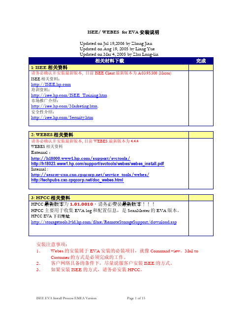
ISEE/ WEBES for EVA安装说明Updated on Jul 19,2006 by Zhang JianUpdated on Aug 19, 2005 by Liang Yue安装注意事项:1.Webes的安装属于EVA安装的必装项目,就像Command view。
Mail to Customer的方式是必须完成的工作。
2.客户网络具备的条件下,尽量说服客户安装ISEE的方式。
3.如果安装ISEE的方式,请务必安装HPCC。
5. 如果文件版本为5.00.3805或更高,请参“HP ProLiant and Integrity Servers附加支持条件”。
如果文件版本低于5.00.3805或在被支持设备中无法找到该文件,必须安装Microsoft jview文件:msjavx86.exeMSJava_WindowsUpdate.exe (文件完全遗失)a.安装Microsoft jview文件,找到保存ISEE客户端软件目录中ISEEPlatform.exe文件(请参考“下载ISEE客户端软件”)。
双击ISEEPlatform.exe文件。
b.在ISEEPlatform子目录执行下列命令:msjavx86.exec.安装完文件,根据提示重启电脑。
d.注意:如果是升级jview.exe文件,请跳过步骤c。
e.在同一目录,运行MSJava_WindowsUpdate.exef.安装完文件,根据提示重启电脑。
注意:ISEEPlatform是ISEEPlatform.exe文件解压缩的默认子目录。
如果修改路径,必须到修改后的目录中运行步骤a和步骤b的命令。
4)、安装并配置ISEE安装ISEE到缺省目录:C:\Program Files\Hewlett-Packard\ISEE;安装后访问http://localhost:5060/start.html(用户名:admin,密码:isee)进行配置。
HP EVA 4400_RedHatlinux_光纤交换机安装调试

HP EVA 4400_RedHatlinux_光纤交换机安装调试2010年4月目录硬件配置列表 (3)项目说明 (5)拓扑图 (6)一、送货验货 (7)二、硬件上架 (7)三、线缆连接 (8)四、安装系统 (9)五、光纤交换机划zone (27)六、EVA划vd并挂载给服务器 (29)七、安装操作系统补丁、psp包 (36)八、分区、格式化、mount vd (37)九、网卡绑定 (40)十、测试 (41)附件1机柜图 (42)附件2操作系统安装要求 (43)硬件配置列表客户的应用是以计算和数据写入为主,一个计算周期比较长,数据在计算完成后再写入存储中,如果在计算或写入的过程中系统出现故障,则整个计算周期的工作就作废,所以对稳定性和容错要求很高。
因此在整个项目中,电源和数据链路都是冗余的,在硬件安装的过程中也要十分仔细,以保证整个系统的可用性。
6台HP DL360G6服务器安装linux操作系统用作运算,每台服务器在系统层面是独立的,双端口光纤卡分别经冗余的光纤交换机连接EVA4400,运算的结果存储在EVA上,下面拖三个磁盘柜,给每个服务器划分4个vd(virtual disk的容错级别是RAID5),可用容量在9T多。
一个计算周期完成后,把所有数据备份在磁带中。
服务器之间的通信能过千兆以太网交换机,EVA管理模块上的RJ-45网口也连接在交换机上以放便管理。
双UPS分别连接两路市电,给整个机柜供电。
整个机柜部署完成后,独立于周围的环境,只有两根市电输入机柜,一根网线连其他机柜的交换机用作管理。
项目的实施人员至少需要三位。
项目经理管全局工作安排与组织、与客户销售以及HP沟通协调、实施监督核查,另两位工程师分工负责对应的实施事项。
这样工作才会顺利有序,少出差错。
项目实施过程中需要携带的工具:活动扳手、斜口钳、多功能螺丝刀、小螺丝刀(加光驱用)、扎线带、标签打印机(或打印好的标签)、手写标签纸、SmartStart8.30x64光盘等。
eva-hp 存储安装
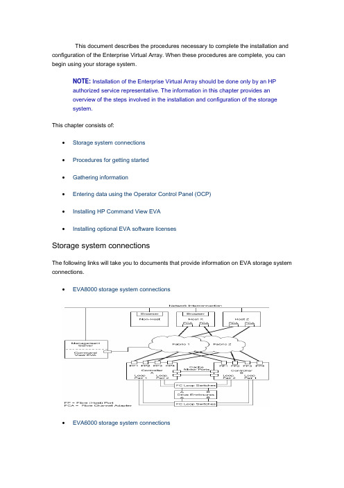
This document describes the procedures necessary to complete the installation and configuration of the Enterprise Virtual Array. When these procedures are complete, you can begin using your storage system.NOTE: Installation of the Enterprise Virtual Array should be done only by an HPauthorized service representative. The information in this chapter provides anoverview of the steps involved in the installation and configuration of the storagesystem.This chapter consists of:∙Storage system connections∙Procedures for getting started∙Gathering information∙Entering data using the Operator Control Panel (OCP)∙Installing HP Command View EVA∙Installing optional EVA software licensesStorage system connectionsThe following links will take you to documents that provide information on EVA storage system connections.∙EVA8000 storage system connections∙EVA6000 storage system connectionsEVA4000 storage system connectionsProcedures for getting startedStepResponsibility 1. Gather information and identify all related storagedocum entation. Custom er2. Contact an authorized service representative for hardware configuration information.HP Service Engineer 3. Enter the World Wide Name (WWN) into the OCP. HP ServiceEngineer4. Configure HP Command View EVA. HP ServiceEngineer5. Prepare the hosts. Custom er6. Configure the system through HP Command View EVA.HP ServiceEngineerStep Responsibility7. Make virtual disks available to their hosts. Refer to the storage system software docum entation for each host’s operating system. HP Service EngineerGathering informationThe following items should be available when installing and configuring an Enterprise Virtual Array. They provide information necessary to set up the storage system successfully.∙HP StorageWorks 4000/6000/8000 Enterprise Virtual Array World Wide Name label , which is shipped with the system.∙HP StorageWorks 4000/6000/8000 Enterprise Virtual Array read me first.∙HP StorageWorks 4000/6000/8000 Enterprise Virtual Array release notes.∙The latest HP OpenView Storage Management Server Update, which consists of the management server update CD and its associated documentation, or the latestWindows Server Updateo You can determine the latest update version available by checking the release notes or contacting your authorized service representative to find out how toreceive the latest information.o Additional documentation is available from the following HP web sites:▪/go/eva4000▪/go/eva6000▪/go/eva8000Locate these items and keep them handy. You will need them for the procedures in this document.Host informationMake a list of information for each host computer that will be accessing the storagesystem. You will need the following information for each host:o The LAN name of the hosto A list of World Wide Names of the FC adapters, also called host bus adapters, through which the host will connect to the fabric or fabrics that provide accessto the storage systemo Operating system typeo Available LUN numbersEntering data using the Operator Control Panel (OCP)NOTE: This procedure should be performed by an HP authorized servicerepresentative.Two pieces of data critical to initial setup must be entered into the OCP:∙WWN—Mandatory to complete setup. This procedure should be performed by an HP authorized service representative.∙Storage system password—Optional. A password is a security interlock that allows only specific instances of HP Command View EVA to access the storage system.Setting up a controller pair using the OCPFibre Channel protocol requires that each controller pair has a unique Node WWN.This 16-character alphanumeric name identifies the controller pair on the storagesystem. The Enterprise Virtual Array World Wide Name label identifies the WWN foreach storage system. The Node WWN labels identify the storage system WWN andchecksum (see Figure 1). During the installation of the storage system, two WWNlabels are attached to the rack on both sides of the controller enclosures.Figure 1: Sample node WWN labelNOTE: The controller pair WWN is unique to a controller pair and cannot beused for any other controller pair or device anywhere on the network. Figure 2shows the location of the WWN label, one either side of a controller pair. Thisis the only WWN applicable to any controller installed in a specific physicallocation, even a replacement controller. Once a WWN is assigned to acontroller, you cannot change the WWN while the controller is part of thesame storage system.Figure 2: Location of the World Wide Name label1 - World Wide Name labelEntering the WWNTable "WWN push button functions" lists the push button functions when entering the WWN or the WWN checksum.NOTE: The following sections describe procedures that require use of theOCP. For more information about the OCP, see HP StorageWorks EVA 4000,6000, 8000 - HSV controllers, Identifying and Using.WWN push button functionsButtonFunctionSelects a WWN or checksum character by scrolling up through thecharacter list one character at a tim e. If you select an incorrectcharacter, you can use either or to select the correct character. Moves forward one character. If you accept an incorrect character, youcan m ove through all 16 characters, one character at a tim e, until youdisplay the incorrect character. You can then change the character.Selects a WWN or checksum character by scrolling down through thecharacter list one character at a tim e. If you select an incorrectcharacter, you can use either or to the select correct character.Moves backward one character.Complete the following procedure to assign the WWN to each pair of controllers.Either controller can be used to input the WWN.1. Turn the power switches on both controllers off.2. Apply power to the rack.3. Turn the power switch on both controllers on.NOTE: Notifications of the startup test steps that have been executedare displayed while the controller is booting. It may take up to twominutes for the steps to display.4. The WWN entry display has a 0 in each of the 16 positions.5. Press or until the first character is displayed. Press to acceptthis character and select the next.6. Repeat Step 5 to enter the remaining characters.7. Press Enter to accept the WWN and select the checksum entry mode.NOTE: For the location of the WWN Checksum, see Figure 2.Entering the WWN checksumThe second part of the WWN entry procedure is to enter the two -character checksum, HS, as follows.1. Verify that the initial WWN checksum displays 0 in both positions.2.Pressoruntil the first checksum character is displayed. Pressto accept this character and select the second character.3.Pressor until the second character is displayed. Press Enter toaccept the checksum and exit.4. Verify that the default display is automatically selected. This indicates that thechecksum is valid.NOTE: If you enter an incorrect WWN or checksum, the system willreject the data and you must repeat the procedure.Setting the storage system passwordThe eight-character storage system password feature enables you to restrict certain functions to selected resource managers. Table "System password push buttonfunctions" describes the push button functions when using the password feature.System password push button functionsButtonFunction Selects a password character by scrolling up through the character list one character at a tim e (A –Z and 0–9).Accepts the current character and selects the next character. If youaccept an incorrect character, you can loop through the display, oneposition at tim e, to select the character to be changed.Selects a password character by scrolling down through the character listone character at a tim e. ESC Returns to the default display.ENTER Accepts all the password characters.Installing HP Command View EVAHP Command View EVA is installed on the HP OpenView Storage Management Server or a Windows host and runs in the OpenView environment. Installation may be skipped if the latest version of HP Command View EVA is running. Verify the latest version at the HP web site: /storage/software.htmlTo install a new version, locate the management server update CD -ROM and the associated documentation that was shipped with your storage system. Follow the instructions in the HP OpenView Storage Management Server update installation card to install the new software. Installing optional EVA software licensesIf you purchased optional EVA software, it will be necessary to install the license. Optional software available for the Enterprise Virtual Array includes HP Business Copy and HP Continuous Access. Installation instructions are included with the license.。
EVA更换电池步骤
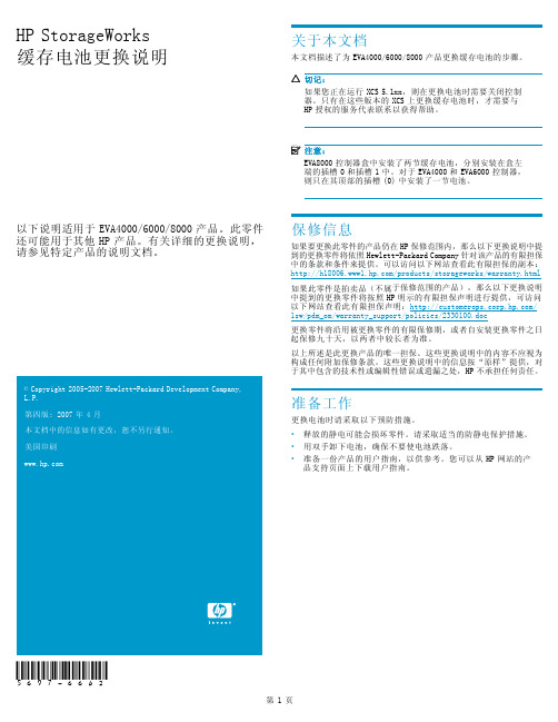
表1 状态指示灯 亮起
故障指示灯 熄灭
如果此零件是拍卖品(不属于保修范围的产品),那么以下更换说明 中提到的更换零件将按照 HP 明示的有限担保声明进行提供,可访问 以下网站查看此有限担保声明:/ 1sw/pdm_om/warranty_support/policies/2330100.doc
2
3
图 1 电池状态指示灯
1. 状态指示灯 2. 故障指示灯 3. 电池 0 4. 电池 1
表 1 中介绍了电池状态指示灯。第一次安装电池时,故障指示灯会 在系统发现新电池时亮起(持续亮起)约 30 秒。然后,电池状态 指示灯将显示电池状态,如表 1 中所述。
图 2 取出电池
1
0180a
第2页
安装电池
将电池放在插槽中尽可能高的位置,然后让电池滑入盒中(图 3 中 的 1)直到完全装入并且安装锁合上 (2)。
2 图 3 安装电池
1
0179a
确认操作正常
更换电池后,通过以下方面的检查验证该组件是否工作正常:
注意: 该组件最长可能需要 10 分钟才能显示正常状态。
• 检查电池状态指示灯。请参见表 1。 • 在第一分钟,两个状态指示灯可能会同时亮起或同时闪烁。 • 然后,状态指示灯 (1) 应该开始闪烁,指示电池正在充电。 新电池可能需要几个小时才能充满电。充电过程中故障指示 灯 (2) 应关闭。 检查状态指示灯后,将前面板安装到盒上,用力将其按入到位。
- 1、下载文档前请自行甄别文档内容的完整性,平台不提供额外的编辑、内容补充、找答案等附加服务。
- 2、"仅部分预览"的文档,不可在线预览部分如存在完整性等问题,可反馈申请退款(可完整预览的文档不适用该条件!)。
- 3、如文档侵犯您的权益,请联系客服反馈,我们会尽快为您处理(人工客服工作时间:9:00-18:30)。
NOTE: IPv6 is supported onቤተ መጻሕፍቲ ባይዱHP Command View EVA 8.0.2 and later.
Contents
1 Preparation ....................................................................................... 9
2 HP Command View EVA software suite .............................................. 17
Installing the software suite on a management server ..................................................................... Typical installation .............................................................................................................. Custom installation ............................................................................................................. Verifying the installation on the management server ...................................................................... Installing the software suite on the management module ................................................................ Verifying the installation on the management module .................................................................... Creating users on Windows ....................................................................................................... Upgrading HP Command View EVA software .............................................................................. Backup file locations ........................................................................................................... Removing the software suite ....................................................................................................... Retaining HP Command View EVAPerf performance data ............................................................... Removing individual components ................................................................................................ Downgrading HP Command View EVA ........................................................................................ 17 17 19 21 21 22 23 23 24 25 25 26 26
HP StorageWorks Command View EVA Installation Guide
Abstract This guide describes how to install HP StorageWorks Command View EVA, HP StorageWorks Command View EVAPerf, HP StorageWorks Storage System Scripting Utility and HP Storage Management Initiative Specification for Enterprise Virtual Array. This guide is intended for customers who are experienced with Enterprise Virtual Arrays, storage area networks, and the tools previously listed.
3 HP Command View EVAPerf .............................................................. 27
Installing HP Command View EVAPerf ......................................................................................... 27
Acknowledgments
Microsoft® and Windows® are U.S. registered trademarks of Microsoft Corporation. Java™ is a U.S. trademark of Sun Microsystems, Inc. Linux® is a U.S. registered trademark of Linus Torvalds in the U.S. and other countries. UNIX® is a registered trademark of The Open Group. Itanium® is a registered trademark of Intel Corporation or its subsidiaries in the United States and other countries.
4 HP Storage System Scripting Utility ..................................................... 29
Part Number: T5494-96384 Eleventh edition: August 2010
Legal and notice information © Copyright 2005-2010 Hewlett-Packard Development Company, L.P. Confidential computer software. Valid license from HP required for possession, use or copying. Consistent with FAR 12.211 and 12.212, Commercial Computer Software, Computer Software Documentation, and Technical Data for Commercial Items are licensed to the U.S. Government under vendor's standard commercial license. The information contained herein is subject to change without notice. The only warranties for HP products and services are set forth in the express warranty statements accompanying such products and services. Nothing herein should be construed as constituting an additional warranty. HP shall not be liable for technical or editorial errors or omissions contained herein.
Server-based management prerequisites ...................................................................................... Software suite .................................................................................................................... HP SMI-S EVA .................................................................................................................... Management server types ................................................................................................... Setting credentials .............................................................................................................. Management server ..................................................................................................... Ensuring successful authorization ................................................................................... Array-based management prerequisites ....................................................................................... HP Insight Remote Support software ............................................................................................ 10 10 12 12 13 13 14 14 15
