HP-EVA存储管理手册
HP StorageWorks EVA4x00 6x00 8x00 M5314 驱动器套式安装指南说
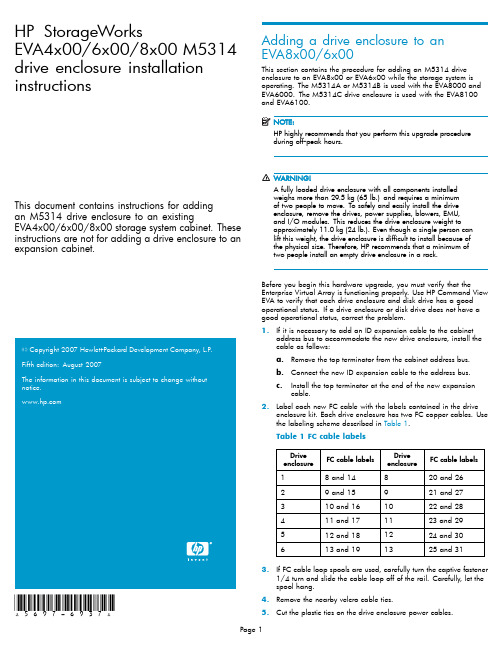
HP StorageWorksEVA4x00/6x00/8x00M5314 drive enclosure installation instructionsThis document contains instructions for addingan M5314drive enclosure to an existingEVA4x00/6x00/8x00storage system cabinet.These instructions are not for adding a drive enclosure to an expansion cabinet.20072007*5697-6937*Adding a drive enclosure to anEVA8x00/6x00This section contains the procedure for adding an M5314drive enclosure to an EVA8x00or EVA6x00while the storage system is operating.The M5314A or M5314B is used with the EVA8000and EVA6000.The M5314C drive enclosure is used with the EVA8100 andEVA6100.HP highly recommends that you perform this upgrade procedureduring off-peakhours.A fully loaded drive enclosure with all components installedweighs more than29.5kg(65lb.)and requires a minimumof two people to move.To safely and easily install the driveenclosure,remove the drives,power supplies,blowers,EMU,and I/O modules.This reduces the drive enclosure weight toapproximately11.0kg(24lb.).Even though a single person canlift this weight,the drive enclosure is difficult to install because ofthe physical size.Therefore,HP recommends that a minimum oftwo people install an empty drive enclosure in a rack.Before you begin this hardware upgrade,you must verify that the Enterprise Virtual Array is functioning e HP Command View EVA to verify that each drive enclosure and disk drive has a good operational status.If a drive enclosure or disk drive does not have a good operational status,correct the problem.1.If it is necessary to add an ID expansion cable to the cabinetaddress bus to accommodate the new drive enclosure,install the cable as follows:a.Remove the top terminator from the cabinet address bus.b.Connect the new ID expansion cable to the address bus.c.Install the top terminator at the end of the new expansioncable.bel each new FC cable with the labels contained in the driveenclosure kit.Each drive enclosure has two FC copper e the labeling scheme described in Table1.Table1FC cable labelsDriveenclosure FC cable labelsDriveenclosure FC cable labels 18and14820and2629and15921and27310and161022and28411and171123and29512and181224and30613and191325and313.If FC cable loop spools are used,carefully turn the captive fastener1/4turn and slide the cable loop off of the rail.Carefully,let the spool hang.4.Remove the nearby velcro cable ties.5.Cut the plastic ties on the drive enclosure power cables.6.Install the drive enclosure snap-in rail kit(part number302465-001).7.Install the drive enclosure into the rack.8.Insert and seat all disk drives and other components into the driveenclosure,but do not connect the cables.9.Connect the AC power to the drive enclosure and do the following:a.Wait for all FC disk drives to spinup.Thefirst drive in the drive enclosure might have the orangeDrive Failure icon lit.This is expected behavior.b.Check the EMU alphanumeric display for errors.See Figure1.Resolve any errors.CXO7373A1.Alphanumeric display2.Function select3.Display group selectFigure1EMU alphanumeric display and controlsc.Verify that the EMU displays00,indicating that the driveenclosure is not connected to the enclosure address bus.d.Verify that the fan LEDs are on and steady.See Figure2.Figure2Enclosure operational status indicationse.On both I/O modules,verify that the Power status indicatoris on and steady.Verify that both port status indicators areoff.See Figure3.f.Resolve any problems before proceeding to the next step.1.Upper port2.Power3.Lower portFigure3I/O module status indicators10.Check the operational status of the FC loops.a.On the controller,verify that the A-side and B-side device portindicators are on and steady.b.Resolve any problems before proceeding to the next step.11.Remove the GBICs from the required ports on the A and B loopswitches.ing a copper FC cable,connect I/O module A to the appropriateA-side loop switch.The A-side of the rack is the right side of the rack,when viewed from the rear.See Figure4and refer to Table2 and Table3to determine which cables and port connections to use.•On an EVA8x00,the location of the drive enclosure in the rack determines the loop switch it connects to.Drive enclosuresmounted in the lower half of the rack(enclosures1through6)connect to loops1A and1B.Drive enclosures mounted in theupper half of the rack(enclosures8through13)connect toloops2A and2B.•An EVA6x00includes a single set of loop switches and all drive enclosures are connected to loops1A and1B.a.Plug the FC cable into the correct port on the A-side loopswitch.b.Route the copper cable through the appropriate cablemanagement arm and radial clip.Do not route the coppercables throughflumes that containfiber optic cables.Instead,route the copper cables through vacantflumes.When you are adding the copper cables to the rack,handlethefiber optic cables with care.If you are not careful,youcan damage thefiber optic cables.c.Coil the excess copper cable and secure the cable behindthe rail with cable ties.d.Plug the cable into I/O module A of the drive enclosure.1.Loop2A 3.Loop1B2.Loop1A 4.Loop2BFigure4Loop locations in the Enterprise rack Table2FC cable connections for I/O module A,loop1ADrive enclosureI/OmoduleFC cable FC loopswitchFC loopswitchport1A81A122A91A103A101A84A111A65A121A46A131A2Table3FC cable connections for I/O module A,loop2ADrive enclosureI/OmoduleFC cable FC loopswitchFC loopswitchport8A202A1 9A212A3 10A222A5 11A232A7 12A242A9 13A252A1113.Verify that the FC connection is operating correctly.a.Verify that the green SFP Status LED on the FC loop switch ison and steady and the Port bypassed LED is off.See Figure5.b.Verify that the corresponding port status indicator on I/Omodule A is on and steady.c.Verify that the corresponding A device port on the controlleris on and steady.The orange Drive Failure icon on thefirst drive in the driveenclosure is turned off.d.Verify thatthe upgraded configuration is working properly, using HP Command View EVA.•Verify that the added drive enclosure has a good status.•Verify that each disk drive in the added drive enclosure has a good status.e.Resolve any problems before proceeding to the next step.FrontBezelCXO7884A1.SFP status 4.Over temp2.Port bypassed 5.Power3.POST fault 6.Loop operationalFigure5FC loop switch status indicatorsing a copper FC cable,connect I/O module B to the appropriateB-side loop switch.The B-side of the rack is the left side of the rack when viewed from the rear.See Table4and Table5to determine which cables and port connections to use.Make sure you are connecting the drive enclosure tocorresponding loop switches.If you used loop switch1A for portA,then you must use loop switch1B.If you used loop switch2A, then you must use loop switch2B.If you fail to connect the driveenclosure to corresponding loop switches,you can make thedata in the other drive enclosures inaccessible.a.Plug the FC cable into the correct port on the B-side loopswitch.b.Route the copper cable through the appropriate cablemanagement arm and radial clip.Do not route the coppercables throughflumes that containfiber optic cables.Instead,route the copper cables through vacantflumes.When you are adding the copper cables to the rack,handlethefiber optic cables with care.If you are not careful,youcan damage thefiber optic cables.c.Coil the excess copper cable and secure the cable behindthe rail with cable ties.d.Plug the cable into I/O module B of the drive enclosure.Table 4FC cable connections for I/O module B,loop 1B Drive enclosure I/O moduleFC cableFC loop switch FC loop switch port 1B 141B 22B 151B 43B 161B 64B 171B 85B 181B 106B 191B12Table 5FC cable connections for I/O module B,loop 2B Drive enclosure I/O moduleFC CcableFC loop switch FC loop switch port 8B 262B 119B 272B 910B 282B 711B 292B 512B 302B 313B 312B115.Verify that the FC connection is operating correctly.a.Verify that the green SFP Status LED on the FC loopswitch ison and steady and the Port bypassed LED is off.b.Verify that the corresponding port status indicator on I/Omodule B is on and steady.c.Verify that the corresponding B device port on the controller is on and steady.d.Resolve any problems before proceeding to the next step.16.Connect the newly added drive enclosure to the enclosure addressbus.See Figure 6for the enclosure numbering.•CAB address ports 8and 14share a common address.When adding a drive enclosure to loop 2on an EVA8x00,make sure drive enclosures are connected to either port 8or port 14.You can use one or the other but not ing both of these ports on the same loop makes it dif ficult to analyze disk problems because the disks in the drive enclosure connected to ports 8and 14appear to have the same addresses.•When adding a drive enclosure to an EVA6x00,do not use address port 7for the enclosure.Address port 7does not receive a hard AL-PA range.a.Verify that the EMU displays a unique enclosure number.b.Verify that the EMUs on the other drive enclosures continue todisplay valid enclosure numbers.c.Wait 15minutes.d.Verify that HP Command View EVA displays the recentlyadded drive enclosure under the Rack element in theNavigation pane.It should no longer be in the Unmappable Hardware folder.e.Verify that the upgraded con figuration is working properly,using HP Command View EVA.•Verify that the added drive enclosure has a good status.•Verify that each disk drive in the added drive enclosurehas good status.0046a-2Figure 6Enclosure numbering17.Repeat the above steps to add each drive e nylon ties to secure the copper FC cables.19.In HP Command View EVA,con figure the additional storagecapacity.See the HP StorageWorks 4x00/6x00/8x00Enterprise Virtual Array user guide and the EVA Best Practices white paper for information on using the new disk capacity.Adding a drive enclosure to an EVA4x00This section contains the procedure for adding an M5314drive enclosure to an EVA4x00while the storage system is operating.The M5314A or M5314B is used with the EVA4000.The M5314C drive enclosure is used with the EVA4100.HP highly recommends that you perform this upgrade procedure during off-peak hours.A fully loaded drive enclosure with all components installedweighs more than29.5kg(65lb.)and requires a minimumof two people to move.To safely and easily install the driveenclosure,remove the drives,power supplies,blowers,EMU,and I/O modules.This reduces the drive enclosure weight toapproximately11.0kg(24lb.).Even though a single person canlift this weight,the drive enclosure is difficult to install because ofthe physical size.Therefore,HP recommends that a minimum oftwo people install an empty drive enclosure in a rack.Before you begin this hardware upgrade,you must verify that the Enterprise Virtual Array is functioning e HP Command View EVA to verify that each drive enclosure and disk drive has a good operational status.If a drive enclosure or disk drive does not have a good operational status,correct the problem.bel each new FC cable with the labels contained in the driveenclosure kit.Each drive enclosure has two FC copper cables. 2.If FC cable loop spools are used,carefully turn the captive fastener1/4turn and slide the cable loop off of the rail.Carefully,let the spool hang.3.Remove the nearby velcro cable ties.4.Cut the plastic ties on the drive enclosure power cables.5.Install the snap-in rail kit(part number302465-001).6.Install the drive enclosure into the rack.7.Insert and seat all drives and other components into the driveenclosure,but do not connect the cables.8.Connect the AC power to the drive enclosure and do the following.a.Wait for all FC disk drives to spinup.Thefirst drive in the drive enclosure might have the orangeDrive Failure icon lit.This is expected behavior.b.Check the EMU alphanumeric display for errors.See Figure1.Resolve any errors.c.Verify that the EMU displays00,indicating that the driveenclosure is not connected to the enclosure address bus.d.Verify that the fan LEDs are on and steady.See Figure2.e.On both I/O modules,verify that the Power status indicatoris on and steady.Verify that both port status indicators areoff.See Figure3.f.Resolve any problems before proceeding to the next step.9.Check the operational status of the FC loops.a.On the controller,verify that the A-side and B-side device portindicators are on and steady.b.Resolve any problems before proceeding to the nextstep.As long as one I/O loop(1A or1B)is operational,storagesystem operation will not be interrupted.Make sure youdisconnect only one loop at a time.Make sure a loop isoperational before disconnecting the other loop.10.Connect the new drive enclosure to I/O loop1A:a.Disconnect the FC cable from device port DP1A on the upperstorage system controller.b.Connect this cable to the lower port on I/O module A of thenew drive enclosure.c.Connect a FC cable from the upper port on I/O module A ofthe new drive enclosure to device port DP1A on the upperstorage system controller.11.Verify that loop1A is operating correctly.a.Verify that the upper and lower port LEDs on I/O module Aare on and steady.b.Verify that device port DP1A on the controller is on andsteady.The orange Drive Failure icon on thefirst drive in the driveenclosure is turned off.c.Verify that the upgraded configuration is working properly,using HP Command View EVA.•Verify that the added drive enclosure has a good status.•Verify that each disk drive in the added drive enclosure has a good status.d.Resolve any problems before proceeding to the next step.12.Connect the new drive enclosure to I/O loop1B:a.Disconnect the FC cable from device port DP1B on the lowerstorage system controller.b.Connect this cable to the lower port on I/O module B of thenew drive enclosure.c.Connect a FC cable from the upper port on I/O module Bof the new drive enclosure to device port DP1B on the lowerstorage system controller.13.Verify that loop1B is operating correctly.a.Verify that the upper and lower port LEDs on I/O module Bare on and steady.b.Verify that device port DP1B on the controller is on and steady.c.Resolve any problems before proceeding to the next step.14.Connect the newly added drive enclosure to the enclosure addressbus.See Figure6for the enclosure numbering.a.Verify that the EMU displays a unique enclosure number.b.Verify that the EMUs on the other drive enclosures continue todisplay valid enclosure numbers.c.Wait15minutes.d.Verify that HP Command View EVA displays the recentlyadded drive enclosure under the Rack element in theNavigation pane.It should no longer be in the UnmappableHardware folder.e.Verify that the upgraded configuration is working properly,using HP Command View EVA.•Verify that the added drive enclosure has a good status.•Verify that each disk drive in the added drive enclosure has good status.15.Repeat the preceding steps to add additional drive enclosures.16.In HP Command View EVA,configure the additional storagecapacity.See the HP StorageWorks4x00/6x00/8x00Enterprise Virtual Array user guide and the EVA Best Practices white paper for information on using the new disk capacity.。
HP StorageWorks EVA的最佳实例
HP StorageWorks EVA的最佳實例HP 諮詢中心技術經理張明福文關於EVA 的規劃,基本上根據三個因素:Cost, Performance, Availability。
客戶常關心的問題包括:「是否要把全部的硬碟都放在同一disk group或二個(以上) group ? 它們之間的Performance,Availability差異如何?使用不同的VRAID level和硬碟故障保護程度 (disk failure protectionlevel),將佔用多少空間,還是多少可用空間 ? 我使用Oracle資料庫,disk group 和data files,redo logs, archive files等檔案,如何規劃才兼具最佳的可用性 (availability) 和性能(performance)」…等等。
一般說來,考慮某一因素可能就無法顧及其他因素,使用者必須分析自己作業環境的需求和什麼是您最重要的因素,HP工程師會瞭解您的環境和需求而為您作最佳規劃,以下以這三個因素分別舉列其最佳實例供您參考,如果您需要更進一步的資料,可參考HP EVA5000和Storage array systems whitepapers 的網址:/storage/arraywhitepapers.htmlCost Considerations.在一disk group使用相同容量的硬碟.只使用一個 disk group (減少保留空間數量 (reserved space) ).儘可能使用更多的硬碟.使用較低性能、較大容量的硬碟不混合不同容量硬碟在同一disk group:在一個disk group裡,EVA保留二倍(Vriad1) 最大硬碟的空間來rebuild data處理一顆或二顆故障硬碟。
例如:一個disk group有16顆36GB 硬碟,它必須保留 (36GB * 2(failure protection level)* 2) 的空間。
HP EVA存储管理手册
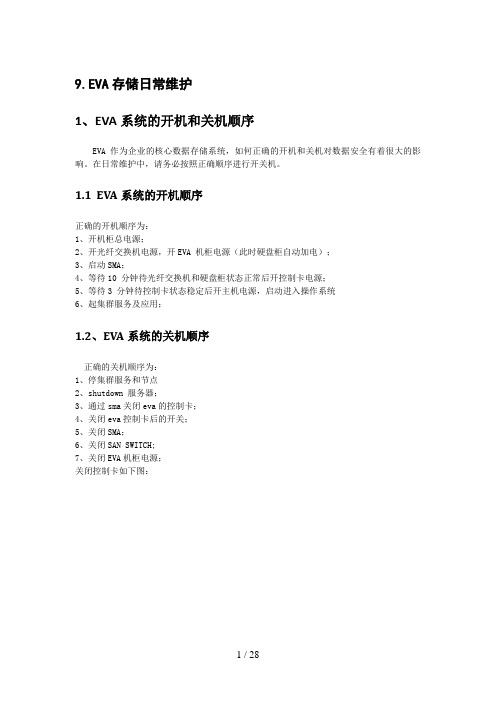
9.EVA存储日常维护1、EVA系统的开机和关机顺序EVA 作为企业的核心数据存储系统,如何正确的开机和关机对数据安全有着很大的影响。
在日常维护中,请务必按照正确顺序进行开关机。
1.1 EVA系统的开机顺序正确的开机顺序为:1、开机柜总电源;2、开光纤交换机电源,开EVA 机柜电源(此时硬盘柜自动加电);3、启动SMA;4、等待10 分钟待光纤交换机和硬盘柜状态正常后开控制卡电源;5、等待3 分钟待控制卡状态稳定后开主机电源,启动进入操作系统6、起集群服务及应用;1.2、EVA系统的关机顺序正确的关机顺序为:1、停集群服务和节点2、shutdown 服务器;3、通过sma关闭eva的控制卡;4、关闭eva控制卡后的开关;5、关闭SMA;6、关闭SAN SWITCH;7、关闭EVA机柜电源;关闭控制卡如下图:2、如何配置EVA存储系统EVA的配置主要有如下步骤:1. 准备相关信息a. 列出需要使用eva存储的主机名、ip等信息.b. 列出所有需连接eva的主机的Fibre Channel adapters (FCAs).c. 查出FCA卡的WWN号.2. 升级相关软件,如command view等(此项为可选项).3. 初始化EVA存储.4. 升级firmware(为可选项)5. 创建disk group.6. 创建主机列表.7. 创建virtual disks.8. 创建 snapshots and snapclones.(需购买相关的license)2.1、初始化 EVA点击初始化图标,eva 将初始化,初始化过程中要求输入存储的名称,如EVA3000/EVA5000 等,该名称将在面板上显示。
初始化会导致所有的数据都会丢失!初始化全过程如下图:点击initialize:点击Advanced options:如图示选择use managerment appliance date/time:对每个Disk Group来说,都有disk failure保护机制,分别为none, single和double,其中, none表示无spare, single表示留出2disk的空间做spare, double 表示留出4disk空间做spare;如硬盘空间足够大,建议选择double,但至少选择single;comment 内容为可选项。
EVA 安装指南

和EVA的第一次亲密接触EVA系列磁盘阵列,在HP的存储架构中,大致处在VA 与XP之间。
EVA 可以使用在HPUX环境下也已经有好一段时间了,苦于华南区一直没有这样的单,所以没有机会亲身体会一下。
这次福州移动终于order了一台EVA5000 (2C2D) 。
八月十八,晴,我和陈英杰(Jacky ) 怀着愉快的心情出发了。
外观 (2)准备工作 (2)EVA硬件安装 (2)EVA配置 (3)起始页面 (4)点击 Storage management appliance 的icon (5)点击 Devices的icon (5)点击HSV element manager (6)Navigation Pane (6)Content Pane (6)点Content Pane的Options,设storage system access和License (7)确认EVA的VCS版本 (8)初始化阵列 (9)初始化阵列续一 (9)添加Host (10)增加Host续一 (11)添加Virtual Disk (12)Present VD to Host (13)在主机上S ECURE P ATH的安装配置 (13)安装 (13)配置 (13)spmgr display (14)打开|关闭Secure Path的Load Balancing (15)更改Secure Path下的设备文件名 (15)Load Balancing (16)配置与优化 (17)Disk Group (17)RAID Level (17)SCSI Queue Depth & IO timeout (18)脚本与自动化操作 (18)外观EVA是单独的一个41U的机柜,颜色的基调是黑色。
’2C’ 是指两个控制器,上有LCD和按钮,’2D’ 是指有两个盘柜(Fiber Channel Drive Enclosure),每个盘柜最多可以安装14块硬盘。
HP_UXEVA8400扩展存储

HP RX7640,RX6600服务器存储扩容第一部分:HP EVA 8400分配LUN1、在HP EVA 8400中添加500G,300G的的Vdisk第二部分:RX7640 RAC(*2) 添加共享卷组1、在RX 7640服务器查找并新添加的500G的存储.ahfpdb1:/#ioscan -m dsfPersistent DSF Legacy DSF(s)========================================/dev/rdisk/disk3 /dev/rdsk/c0t6d0/dev/rdisk/disk3_p1 /dev/rdsk/c0t6d0s1/dev/rdisk/disk3_p2 /dev/rdsk/c0t6d0s2/dev/rdisk/disk3_p3 /dev/rdsk/c0t6d0s3/dev/pt/pt4 /dev/rscsi/c5t0d0/dev/rscsi/c9t0d0/dev/rdisk/disk62 /dev/rdsk/c8t1d3/dev/rdsk/c6t1d3/dev/rdsk/c10t1d3/dev/rdsk/c12t1d3说明:对于HP rx7640服务器,用ioscan -m dsf命令查看磁盘时,一般新添加的磁盘默认排列在最后,本机为disk62.下面的部分说明是多路径映射:/dev/rdsk/c8t1d3/dev/rdsk/c6t1d3/dev/rdsk/c10t1d3/dev/rdsk/c12t1d32、确认存储的正确性,分别确认映射磁盘的大小500Gahfpdb1:/#diskinfo /dev/rdsk/c8t1d3ahfpdb1:/#diskinfo /dev/rdsk/c6t1d3ahfpdb1:/#diskinfo /dev/rdsk/c10t1d3ahfpdb1:/#diskinfo /dev/rdsk/c12t1d33、确认添加的磁盘后,共享的卷组3.1、在节点一创建物理卷ahfpdb1:/# pvcreate -f /dev/rdsk/c8t1d3ahfpdb1:/# pvcreate -f/dev/rdsk/c6t1d3ahfpdb1:/# pvcreate -f /dev/rdsk/c10t1d3ahfpdb1:/# pvcreate -f /dev/rdsk/c12t1d3说明:rdsk 指字符设备ahfpdb1:/#mkdir -p /dev/vgdds --添加卷组名称ahfpdb1:/#ll /dev/*/group --查看现有卷组的分配…… 64 0x000000…… 64 0x010000………… 64 0x050000ahfpdb1:/#mknod /dev/vgdds/group c 64 0x060000 --不能和上面结果重复ahfpdb1:/#vgcreate –s 32 /dev/dsk/c8t1d3 /dev/dsk/c6t1d3 /dev/dsk/c10t1d3 /dev/rdsk/c12t1d3说明:注意此处创建卷组为dsk块设备3.3、在节点一创建逻辑卷LV,并格式化ahfpdb1:/# lvcreate –L 51200 –n lv_ddsdata /dev/vgddsahfpdb1:/# newfs –F hfs /dev/vgdds/rlv_ddsdata3.4、在节点一已经创建的卷组上去激活ahfpdb1:/#vgchange –a n /dev/vgdds说明:激活卷组的命令vgchange –a y /dev/vgdds3.5、在节点一预删除卷组ahfpdb1:/# vgexport -p -s -m /tmp/vgdds.map /dev/vgdds3.6、在节点二创建group节点文件ahfpdb2:/#mkdir –p /dev/vgddsahfpdb2:/#mknod /dev/vgdds/group c 64 0x010000 --(该节点一定要和第一台机器一致)3.7、将节点一的vgdds.map文件拷贝到节点二ahfpdb1:/#rcp scp1:/tmp/vgdds.map scp2:/tmp/vgdds.map说明:scp1:用节点一的IP地址或主机名替换,scp2:用节点一的IP地址或主机名替换。
EVA系列存储讲解

EVA的顺序为: • 开机柜总电源 • 开光纤交换机电源 • 开EVA 机柜电源( 此时硬盘柜自动加电) • 启动SMA • 等待10 分钟待光纤交换机和硬盘柜状态正常后开控制卡电源 • 等待3 分钟待控制卡状态稳定后开主机电源, 启动进入操作系统 • 起集群服务及应用
HP StorageWorks Enterprise Virtual Array
EVA 产品介绍及结构
EVA的优点
EVA是HP StorageWorks Disk Array产品,具有以下优点 : 虚拟化特性: 提供最优架构,提高性能,优化磁盘的使用率,
便于动态的存储扩展 可管理性: 可管理大型SAN配置, 缩短管理时间,降低成本 几乎即时的快速克隆: 可立即使用克隆复制, 大大节省时间几
EVA系统日志有四类: --Management Event Log --Controller Event Log --Controller Termination Event Log --NT Event Log 前三个log我们可以通过EVA的command view来获得,NT event
日志事件的实例
点击more detail查看该事件的详细描述
收集EVA系统日志
选择get log file 或get parse file
问答与实机操作
EVA的配置主要有如下步骤: 1. 准备相关信息 a. 列出需要使用eva 存储的主机名 、 ip 等信息. b. 列出所有需连接eva 的主机的Fibre Channel adapters (FCAs). c. 查出FCA卡的WWN号. 2. 升级相关软件, 如command view等( 此项为可选项) . 3. 初始化EVA存储. 4. 升级firmware( 为可选项 ) 5. 创建disk group. 6. 创建主机列表. 7. 创建virtual disks. 8. 创建 snapshots and snapclones.( 需购买相关的license)
HP StorageWorks EVA软件兼容性参考说明书

Y
Y
HP StorageWorks Replication Solutions Manager 1.0 and later
Y
Y
HP StorageWorks Command View
EVA 3.3 and later2
Y
Y
Y
Y
Y
Y
Y
Y
Y
Y
HP StorageWorks Secure Path (required for multipath configurations)
Storage Management Appliance
G1, G2, G3
HP ProLiant Storage Server
HP ProLiant DL380 G4 Storage Server (base model) HP Proliant DL380 G4 Storage Server (SAN model) HP ProLiant DL585 Storage Server HP Proliant DL585 Dual Core Storage Server Note: In most configurations, the HP ProLiant DL380 SAN model is preferred.
Y
Y
Y
SSSU Build 7 for 3.2
HP Command View EVA 4.0
EVAPerf 1.0 SMI-S EVA 4.0
N
Y
N
SSSU 4.0.18
EVA3000/EVA5000 VCS 3.0141 VCS 3.0202
Y
Y
Y
Y
Y
Y
磁盘存贮器(HP eva4400)详细需求

容量
本次配置容量=18TB,最大容量可扩展至96TB
IPOS
140000
支持主机个数
256
客户端支持
不收费
带宽
>=1550MB/s
最大Raid集
最大RAID集的磁盘数量≥16
是否OEM
需要原厂商设备,非OEM产品。
操作系统
控制器采用专用操作系统(非Windows、linux的改造版)
磁盘混插
在同一硬盘笼内实现FC和ATA硬盘混插
磁盘存贮器(HP eva4400)详细需求
指标
描述
品牌
HP
机型
全光纤架构SAN磁盘阵列
阵列控制器
标配2个RAID控制器实现冗余,采用Risc处理器。
阵列高速缓存
当前配置阵列高速缓存必须满配且数量=4GB
后端接口类型
FC:4(4Gb)
后端通道数量
4
最大硬盘个数
最大硬盘个数>=90
硬盘可靠性
在有冗余硬盘空间的情况下,同一个Raid组中,支持超过2块以上的硬盘渐次损坏
后端交换架构
磁盘阵列使用交换架构连接后端磁盘抽屉
主机连接
在阵列允许的情况下,不限制安装主机数量,未来增加任意平台,任意主机数量不需要额外付费。如需付费,请投标时配齐。
RAID支持类型
支持VRAID0,VRAID1,VRAID10、VRAID5
HP StorageWorks Continuous Access EVA实现指南说明书
Asynchronous write mode (enhanced)
•
•
•
•
•
•
Asynchronous write mode (standard)
•
•
Auto suspend on full copy (set at creation)
•
•
•
•
•
Auto suspend on links down (set at creation)
DR group log file size (user configurable)3
•
•
•
•
•
•
•
•
•
•
2x the combined size of DR group
members (cannot be changed)
Smaller of: – 2,047.99 GB maximum virtual disk size – Remaining space in disk group in which the DR group log resides – The sum of the sizes of the members within the DR group2
•
•
•
•1
•1
100 GB (Synchronous and Asynchronous)
Maximum log file size within these parameters: – 2,047.99 GB maximum virtual disk size – Greater than 136 MB4, 5 – Less than or equal to the available capacity in the source log disk group. The capacity selected must also be available in the destination log disk group.
EVA维护手册

HP虚拟带库vls6000管理手册前言尊敬的客户,首先欢迎您购买HPVirtualLibrarySystem系列存储。
尊敬的系统管理员,您选择了惠普的产品,同时也就选择了惠普的服务。
您在任何时候都不是孤立无援,在您们的身后有一个惠普计算机系统响应中心在时刻准备着为您提供技术服务。
不论是系统故障,还是存储方面的技术问题,您都可以致电惠普响应中心。
该中心配有经验丰富的软件、硬件工程师,可以通过电话或计算机远程访问确定故障点,以最快速度解决用户问题。
所以,在系统运行发生故障时,欢迎拨打惠普计算机系统服务响应中心电话请求援助。
联系方法是:1)800-810-7000(免费服务电话)目录前言.................................................................................................................. 错误!未指定书签。
目录 ................................................................................................... 错误!未指定书签。
第一章、有关机房现场环境............................................................................................ 错误!未指定书签。
一、机房总体要求....................................................................................................... 错误!未指定书签。
二、机房内环境要求 ................................................................................................... 错误!未指定书签。
HP EVA Storage training slides

2022年2月25日星
13 期五
惠普机密。 仅供惠普和渠道合作伙伴内部使用。 可提供给签署了NDA的特定客户。
EVA阵列集成软件
• EVA软件组合更新 • 继续支持之前所有EVA型号
− HP StorageWorks Command View EVA软件(v9.0) − HP StorageWorks Replication Solutions Manager软件
EVA4400 EVA6400 EVA8400
新!
2022年2月25日星
7
期五
惠普机密。 仅供惠普和渠道合作伙伴内部使用。 可提供给签署了NDA的特定客户。
EVA企业虚拟阵列
• 2007年10月,惠普交付了第40,000台EVA • 2008年6月,惠普交付了第50,000台EVA • 2008年12月,惠普交付了第60,000台EVA • EVA的可用性可达99.999%,极大地缩短了意外宕机时间 • 客户的正常运行时间预计达10亿小时 • 过去2年发运的EVA的数量比之前4年的都多 • 预计未来2年发运的EVA的数量将超过过去4年 • 截止到2008年4月,EVA的销量已经连续16个季度实现两
• 降低成本 • EVA不会在容量和性能方面出现瓶颈 且易于重新部署,因此客户可根据自 身的需求配置合适的存储容量。
• 降低风险 • EVA架构的可用性可达到5个9 (99.999%)
• 加速增长 • Dynamic Capacity Manager和LUN 伸缩能力可帮助客户轻松地扩展、收 缩和重新部署其存储环境
EVA4400/6400/8400 功能强大,简单易用
SWD Presales Team
© 2008 Hewlett-Packard Development Company, L.P. 本文所含信息如有更改,恕不另行通知。
HP存储管理解决方案完整篇.doc

HP存储管理解决方案1 HP存储管理解决方案日程1.存储管理面临的挑战2.HP SE存储管理解决方案3.HP EV A管理软件存储架构管理面临的挑战Specialized Pt.ToolsIT Staff Resources•/ 存储容量增长,存储架构复杂•/ 没有有效工具管理存储架构•/ 对容量和性能管理没有直观的工具•/ 多个独立的工具,不能实现统一管理Application InfrastructureHiCommandControlCenter ECM/Solaris Fabric Tools EFCM Linux NetBackup Applications Storage Servers File Systems Operating Systems DB2Navisphere Network Databases存储架构管理的问题面对不断增加的存储设备,我们如何在不增加甚至的情况下进行存储设备的管理? 当需要规划新的SAN 、数据迁移或数据整合时,信息!所有的存储管理人员都可以掌握对异构存储的管我随时都了解我的存储架构中系统使用情况•对SAN 架构的各个部件的关系很清楚•异构复杂的存储环境!减少技术人员•我知道所有的从管理软件入手!•理•提高效率是核心!HP存储管理解决方案1第2页存储架构管理的问题4 期五•Discovery •Event management •Topology •Path management •Reports•CLI / AP I’sE x c h a n g e V i e w e rO r a c l e V i e w e rS y b a s eV i e w e rF i l e S y s t e m V i e w e rG l o b a l r e p o r t e rP r o v i s i o n i n g M a n a g e rC h a r g e b a c k M a n a g e rR e p o r t d e s i g n e rHP 存储域管理软件Storage EssentialsOptional value-add plug-insHP Storage Essentials –Enterprise Edition Required •Event management •Path management •CLI / AP •Capacity•Performance•Tool kit for custom scripts•Role-based security•Historical & future trends•Policy Managerpurchase存储域管理软件所提供的功能•−SAN 网络管理Management−SRM−Storage资源供应−应用QoS管理•一次安装,按需激活•最少的“代理”安装“Application-to-2010年4月2日星应用模块数据库表文件系统卷管理HBA SAN交换机存储6 期五完全的、集成的、开放的管理Common Information Model 应用•全系统拓朴•可用性•性能•容量管理•评估/计费主机•逻辑文件管理•存储资源管理网络•SAN的网络管理•设备管理存储•报告•容量规划•存储整合•管理策略与规则你不能管理或优化你不知道的!•存储的效能与使用率?−有多少数据?−数据分布在那里?−有多少与业务无关的数据?−有多少数据是重复的、陈旧的?−数据的“年纪”了?−存储性能如何?−什么时候剩余的空间变小了?存储容量消耗的速度怎么样?−什么时候需要更多的存储?如何做容量预测?2010年4月2日星8 期五HP存储管理解决方案1第3页全系统范围的容量管理-最大化现有资源的使用率,确保可用性•系统范围容量视图−过剩容量−未充分使用容量−风险中资源−数据集中的备用容量•关联的各层面容量表现−应用−主机−交换机−存储系统•趋势与推断提供精确预告2010年4月2日星9 期五文件级SRM-数据生命周期管理•详细的文件大小、类型,年龄分析−数据生命周期管理和数据备份的计划Plug-in for File server你不能管理或优化你不知道的!•下面的事情花费了你多少时间?−SAN存储网络设备的配置与调整−容量的管理与计划−性能的监控与调整−存储与相关资源的供应−存储管理报告−故障事件与问题的管理2010年4月2日星11 期五性能的路径管理•检测•表现−应用(数据库)−主机−交换机−存储•趋势预报SAN 资源关联-简化管理。
HPStorageWorksEVA企业虚拟化存储讲解

选择disk group中的硬盘数目和protection level:
输入alarm level,建议为default值(95%),设好该值后,在分配空间时,不要使用超 过可用空间的95%,否则会alarm,该选项主要是在用户数据量大空间不够时提醒用户做扩 容等;
2. 3、如何浏览和更改组的属性
2.4.2、添加主机
添加主机的过程如下:
点击Add host:
输入主机名(该名称为用户自己定义的,不一定与实际主机名相同)IP地址为可选项, 可以不输,建议输入,便于识别该主机;
Save changes — 保存对该页所做的改动。 Add disks —添加新的物理盘到该group中. Locate — 定位组中的某个disk的位置,locate off取消locate动作. Delete — 删除组,会删除组内的数据. 不能删除Default Disk Group. 更改disk group name, disk failure protection level, occupancy alarm level, and comments by entering new values and clicking Save changes.
EVA特性对比
HP Enterprise Virtual Array 4400
EVA存储配置过程
EVA系统的开机和关机顺序
EVA 作为企业的核心数据存储系统,如何 正确的开机和关机对数据安全有着很大的 影响。
在日常维护中,请务必按照正确顺序进行 开关机。
EVA系统的开机顺序
• 停集群服务和节点 • shutdown 服务器; • 通过sma关闭eva的控制卡; • 关闭eva控制卡后的开关; • 关闭SMA; • 关闭SAN SWITCH; • 关闭EVA机柜电源;
HP Storage Works EVA企业虚拟化存储
点击Next Step, 选择一个LUN ID。每个VD的LUN ID就是不同的,而对就不同的Host, 同一 个VD对就的LUN ID最好是一样的。 点击Finish确定。
点击OK,后台将会对group的disk做leveling,生成VD需要一点时间,取决于这个 VD的大小。
2.7、如何更改 vdisk属性
具体创建步骤如下:
选择vdsik或其中的某个vdsik folder,点击create vdisk:
在navigation pane选中Virtual Disks, 与管理Host类似,可以先生成一个Folder, 来对VD分 类。 在Content Pane点击Create Folder, 输入一个名字,点击Finish确定。 在navigation pane选中Folder, 然后在右边点击Create VD Family. 按需要输入VD的名字, RAID级别,大小等。 OS Unit Id是针对TRU64/VMS系统的,对于HPUX来说不需要更改。 Present to host, 可以在这里选择某一台可以访问到这个VD的host.
在左侧选择需要更改的vdisk:
该页可以修改的选项为cache policies,vdisk大小,写保护等;点击presentation:
该页可以修改os id及prefer mode。同时,还可以present/unpresent vdisk给主机。 所有修改做完后都必须要点击“save changes”方可生效。 在修改vdisk配置时应注意: 尽管EVA支持在线增大vdisk的空间(出于数据安全的考虑,不可以减小),但必须操作系 统支持在线扩容才可以。支持在线扩容的系统有WINDOWS2000及以上版本、tru64、 hp-ux等(某些系统需要购买相关软件)。 如果操作系统不支持,请不要进行扩容,以免数据丢失。如确需扩容,建议先进行系 统备份在重建vdisk,最后把数据在恢复到新的vdisk上。
HP StorageWorkEVA管理简介
Navigation pushbuttons
Pushbutton
Down
Function
From the default display, moves from System Info to Fault Management to Shutdown Options to System Password Moves back through the main menu items Moves through sub-menu items Moves back through sub-menu items Used for No selections and to return to the default display Used for Yes selections and to progress through menu items
Management server with
Fabric 2 Fabric 1
FP1 Loop pair 1
FP2 Loop pair 2
Mirror ports
FP1 Loop pair 2
FP2 Loop pair 1
Controller A
Controller B
B B Drive enclosures A A
HP StorageWorks 4000/6000/8000 Enterprise Virtual Array 管理简介 Rev. 5.32
安装计划支持中心
中国惠普有限公司
内容
Product Overview Rack, Cabling, and Configurations HSV200/HSV210 Controller Device Management Event Logs Shutdown and Restart EVA
HP StorageWorks Enterprise Virtual Arrays (EVA) 管理
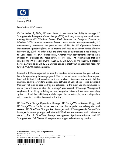
© Hewlett-Packard Company, 2005 All Rights Reserved.Printed in the U.S.A.All other product names mentioned herein may be trademarks of their respective companies.The information in this document is subject to change without notice.January 2005Dear Valued HP Customer:On September 1, 2004, HP was pleased to announce the ability to manage HP StorageWorks Enterprise Virtual Arrays (EVA) with any industry standard server running Microsoft® Windows Server 2003 Standard or Enterprise Editions or Windows 2000 Server or Advanced Server. Based on this new support model, HP simultaneously announced the plan to end of life the HP OpenView Storage Management Appliance (SMA) in six months and, thus, to discontinue sales effective February 28, 2005. HP offers a full line of the most popular servers in the industry to fill your needs for EVA management, whether your requirements include high availability, expandability, redundancy, or low cost. HP recommends that you consider the HP ProLiant DL145, DL360G4, DL560G4, or the DL380G4 Storage Server SAN Model or DL580 G2 Storage Server to meet your management needs for future EVA SAN implementations.Support of EVA management on industry standard servers means that you will now have the opportunity to manage your EVA in a manner more complimentary to your firm’s established IT infrastructure business practices. You may now also install the antivirus, backup, or system management software of your choice – and download Microsoft hot fixes as soon as they are released. In the event you should choose to do so, you will soon be able to ‘re-image’ your current HP Storage Management Appliance II or III by installing a new, supported Microsoft Windows operating system.. HP will be publishing a white paper that describes this new configuration with conversion considerations and instructions.HP OpenView Storage Operations Manager, HP StorageWorks Business Copy, and HP StorageWorks Continuous Access are now also supported on industry standard servers. HP OpenView Storage Area Manager and HP StorageWorks Secure Path Manager have always supported Microsoft Windows environments and continue to do so. The HP OpenView Storage Management Appliance software and HPStorageWorks HSG Element Manager are not supported on industry standard© Hewlett-Packard Company, 2005 All Rights Reserved.Printed in the U.S.A.All other product names mentioned herein may be trademarks of their respective companies.The information in this document is subject to change without notice.servers. However, HSG Element Manager customers who choose to move to an industry standard server for HSG-based array management are still supported with HP StorageWorks Command Console and HP StorageWorks Command Scripter. HP OpenView Storage Provisioner has been discontinued and will not be supported on the SMA after March 31, 2008.HP plans to support the Storage Management Appliance and Storage Management Appliance software v2.1 and affiliated Service Packs, HSG Element Manager, Command Console, and Command Scripter until December 31, 2008. This support is likely to include any required SMA software updates to support ACS firmware for HSG-based arrays, VCS firmware for EVA-based array releases, EVA replication management software qualification, browser qualification, Microsoft security-based hot fix qualification, defect fixes, and select antivirus, backup, and system management software qualification. Please refer to the SMA support matrix that is published on the web at /products/sanworks/managementappliance/specifications.htmlfor information regarding the most current hardware, firmware, software, and browser support.Be sure to consult your sales representative with any questions or for information related to final orders for the HP OpenView Storage Management Appliance.Sincerely,Thomas D. RallensDirectorStorageWorks DivisionHewlett Packard Company。
HP StorageWorks EVA4400 M6412 drive enclosure installation instructions
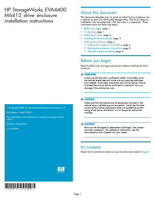
HP StorageWorks EVA4400 M6412drive enclosure installation instructions20082008*5697-7403*About this documentThis document describes how to install an M6412drive enclosure into a cabinet as part of an EVA4400storage array.The drive enclosure installation may be performed while the array is in operation.These instructions cover the following topics:•Before you begin,page1•Kit contents,page1•Attaching the rails,page2•Installing the drive enclosure,page3•Cabling the enclosure,page4•Cabling the enclosure while offline,page4•Cabling the enclosure while online,page5•Alternate enclosure cabling,page6Before you beginRead the following warnings and cautions before installing the driveenclosure.Make sure that the rack is sufficiently stable.If provided,lowerthe cabinet leveler feet and make sure any required stabilizersare installed.If provided,extend the rack anti-tip device.Failureto extend the anti-tip device could result in personal injury ordamage if the cabinet tipsover.Make sure that the cabinet and all equipment mounted in thecabinet have a reliable ground connection.Verify that the totalcurrent of the cabinet components does not exceed the currentrating of the power distribution unit or the power distributionmodules.Parts can be damaged by electrostatic er properanti-static protection.For additional information,see thedocumentation that shipped with your system.Kit contentsCheck the kit contents to make sure you have the items listed in Figure1.1Drive enclosure5Rails with –03brackets 2Eight disk drive blanks (may comepreinstalled inenclosure)6Two Fibre Channel copper cables3–04brackets (not used)7Two enclosure power cords4Pins for round-hole cabinet conversionFigure 1Kit contentsAttaching the railsThe cabinet rail kit supplied with the drive enclosure comes con figured for square-hole cabinets.If you need to convert the rails for a round-hole cabinet,perform the following steps:Do not remove the pins from the ends of the cabinet rails unless you are converting the rails for use in round-hole cabinets.These load-bearing pins are designed to fit throughthe holes without being removed.1.Locate the bag of eight round-hole pins that is included in thecabinet rail e a No.2Phillips screwdriver to remove the standard pins fromthe front and back of the left and right rails (four on each rail).See Figure 2.Figure 2Square hole to round hole cabinet conversion 3.Attach the round-hole pins into the eight holes on the rails wherethe standard pins were removed.To attach the rails to the cabinet:The designation of left and right rail is made when looking at the front of the rack.The rails are marked by an R (right)and L (left)stamped on the metal.1.Insert the rear end of the right rail into the inside back ofthecabinet until the pins partially extend through the holes in the cabinet upright.2.Squeeze the scissors latch together to insert the rail and pins thoughthe cabinet upright holes until the latch engages.See Figure 3.3.gl0124Figure8Tighten drive enclosure to cabinet 4.Reattach the front bezel covers.5.At the rear of the cabinet,slide the shipping retaining bracketforward on both rails until the tab engages the slot in the drive enclosure.Tighten the bracket thumbscrews.6.Populate the enclosure with available disk drives (not included withthis kit),starting with the lowest number in Figure 9,and continuing in order until you have inserted the desired number.If installing multiple drive enclosures,balance the quantity and sizes of disk drives between the enclosures as evenly as possible.Figure 11Inserting a drive blankCabling the enclosureTwo methods are described for cabling a new drive enclosure.The online method allows a drive enclosure to be added to a powered operational array.The of fline method describes cabling an array that has been powered down.The of fline method is preferred if downtime is available.One controller enclosure (with two controllers)can support up to eight drive enclosures.The power cords are supplied in two different colors should you decide to use the colors to denote sides of the cabinet.For example,you can locate all gray power cords on the left side of the cabinet,and all black power cords on the right side.for preexisting cabling when another of the array.dashed between the drive enclosures show cables that are added.Unplug the Fibre Channel cable from I/O module A port P2of the drive enclosure nearest the newly installed drive enclosure,and plug it into the P2port of I/O module A of the newly installed drive enclosure (1,Figure 13).This should be a long cable with the far end connecting to controller 2port DP1–A in a con figuration with all the drive enclosures installed above or below the controller enclosure.If drive shelves are installed above and below the controller enclosure,see Figure 14.gl012212341Connects installed I/O module A,port 2to controller 2,port DP1–A2Connects installed I/O module A,port 1to existing I/O module A,port 23Connects installed I/O module B,port 2to controller 1,port DP1–B4Connects installed I/O module B,port 1to existing I/O module B,port 2Figure 13Addition of drive enclosure to arraying a Fibre Channel copper cable provided in your kit,plug oneend into the P2port of I/O module A that was unplugged in the previous step,and plug the other end into port P1of I/O module A in the newly installed drive enclosure (2,Figure 13).4.Perform steps 2and 3on I/O module B of the newly installed driveenclosure.The results are the Fibre Channel cable on I/O Module B port 2of the nearest drive enclosure is moved to I/O module B port 2of the newly installed drive enclosure (3,Figure 13).In addition,a new Fibre Channel copper cable is installed between I/O Module B port P2of the preexisting drive enclosure and I/O module B port 1of the newly installed drive enclosure (4)ing a power cord provided in your kit,plug one end into a driveenclosure power supply and the other end into a cabinet power distribution module.6.With the remaining power cord,connect the other power supply toa cabinet power distribution module.7.Press the Power On/Standby button on the power UID bezel(located at the rear of the drive enclosure)and hold it down long enough to power up the installed enclosure.8.Power on any other drive enclosures attached to the array andvisually check that the enclosures power on without errors.Wait at least one minute after all the enclosures are powered on for the drives to spin up and stabilize.9.Power on the controller enclosure by pressing the power button onthe power UID bezel until the enclosure responds (it may take up to 10seconds for the controller enclosure to power on).Wait five minutes for the array to stabilize.10.Verify that I/O modules A and B on the added enclosure havebeen assigned an index number of the next higher enclosurenumber.For example,if the previous highest index number was “3,”then the installed enclosure should display “4.”11.In HP Command View EVA,verify that the newly installed driveenclosure appears in the array hardware pane,and that the I/O modules show a good operational status.Cabling the enclosure while onlineing a power cord provided in your kit,plug one end into thedrive enclosure power supply and the other end into a cabinet power distribution module.You will brie fly hear a rush of air as power is applied,and the LEDs on the power UID flash.The power UID standby switch LED remains amber.2.With the remaining power cord,connect the other power supply toa cabinet power distribution module.The power UID power switch LED turns green.The I/O module index number will likely display 00,but if not,ignore the index number at this time.3.Figure 12shows the cabling for an array with one controllerenclosure and three drive enclosures.As a general cabling guideline,the P1port on the I/O module receives input from another I/O module or a controller,and the P2port is used for output to another I/O module or controller.In the steps performed below,one side of the drive enclosure (ports P1and P2of I/O module A on the left side)is cabled,and then I/O module B is cabled.Either I/O module can be cabled first as long as the other I/O module ports are not unplugged until cabling is complete on the first I/O module.This allows the controller to redundantly manage the storage while the cables are brie fly pulled and reconnected on one side.4.Figure 13shows the cabling when another drive enclosure isadded to the bottom of the array.The dashed lines leading to the controller enclosure show cables that are moved,and dashed lines between the drive enclosures show cables that are added.Unplug the Fibre Channel cable from I/O module A port P2of the drive enclosure nearest the newly installed drive enclosure,and plug it into the P2port of I/O module A of the newly installed drive enclosure (1,Figure 13).This should be a long cable with the far end connecting to controller 2port DP1–A in a con figuration with all the drive enclosures installed above or below the controller enclosure.If drive shelves are installed above and below the controller enclosure,see Figure 14.ing a Fibre Channel copper cable provided in your kit,plugoneend into the P2port of I/O module A that was unplugged in the previous step,and plug the other end into port P1of I/O module A in the newly installed drive enclosure (2,Figure 13).Wait for the port to become visible with HP Command View EVA.With only one I/O module from the newly added enclosure cabled to the array,there will be HP Command View EVA warnings that indicate disk drives in the system are onlyconnected on one of the redundant Fibre Channel loops.This is to be expected,and the warnings should clear as soon as the other I/O module is connected.6.Perform steps 4and 5on I/O module B of the newly installed driveenclosure.The results are the Fibre Channel cable on I/O Module B port 2of the nearest drive enclosure is moved to I/O module B port 2of the newly installed drive enclosure (3,Figure 13).In addition,a new Fibre Channel copper cable is installed between I/O Module B port P2of the preexisting drive enclosure and I/O module B port 1of the newly installed drive enclosure (4).7.Verify that I/O modules A and B on the added enclosure havebeen assigned an index number of the next higher enclosurenumber.For example,if the previous highest index number was“3,”then the installed enclosure should display“4.”8.In HP Command View EVA,verify that the newly installed driveenclosure appears in the array hardware pane,and that theI/O modules show a good operational status. Alternate enclosure cablingDrive enclosures may have to be installed where room is available in a cabinet.Figure12and Figure13show drive enclosures mountedin a cabinet on just one side of the controller enclosure.When drive enclosures are mounted on both sides of the controller enclosure,the cabling is logically the same,in that all the drive enclosures are connected serially.In this case,the long Fibre Channel cable goes from the I/O module P2port of the last drive enclosure on one sideof the controller enclosure to the farthest drive enclosure on the other side of the controller enclosure.The last drive enclosure in the series (near the controller enclosure)completes the loop back to the controller. Figure14shows this cabling configuration with drive enclosures above and below the controller enclosure in an array.Installing a drive enclosure above or below this configuration would keep the same pattern of cabling between the drive and controller enclosures.gl0125 Figure14Array cabling for drive enclosures on both sides of the controller enclosure。
eva-hp 存储安装
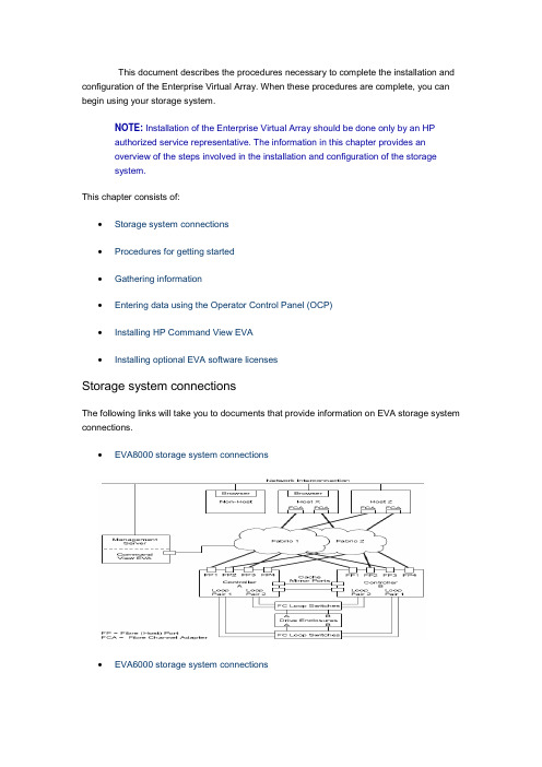
This document describes the procedures necessary to complete the installation and configuration of the Enterprise Virtual Array. When these procedures are complete, you can begin using your storage system.NOTE: Installation of the Enterprise Virtual Array should be done only by an HPauthorized service representative. The information in this chapter provides anoverview of the steps involved in the installation and configuration of the storagesystem.This chapter consists of:∙Storage system connections∙Procedures for getting started∙Gathering information∙Entering data using the Operator Control Panel (OCP)∙Installing HP Command View EVA∙Installing optional EVA software licensesStorage system connectionsThe following links will take you to documents that provide information on EVA storage system connections.∙EVA8000 storage system connections∙EVA6000 storage system connectionsEVA4000 storage system connectionsProcedures for getting startedStepResponsibility 1. Gather information and identify all related storagedocum entation. Custom er2. Contact an authorized service representative for hardware configuration information.HP Service Engineer 3. Enter the World Wide Name (WWN) into the OCP. HP ServiceEngineer4. Configure HP Command View EVA. HP ServiceEngineer5. Prepare the hosts. Custom er6. Configure the system through HP Command View EVA.HP ServiceEngineerStep Responsibility7. Make virtual disks available to their hosts. Refer to the storage system software docum entation for each host’s operating system. HP Service EngineerGathering informationThe following items should be available when installing and configuring an Enterprise Virtual Array. They provide information necessary to set up the storage system successfully.∙HP StorageWorks 4000/6000/8000 Enterprise Virtual Array World Wide Name label , which is shipped with the system.∙HP StorageWorks 4000/6000/8000 Enterprise Virtual Array read me first.∙HP StorageWorks 4000/6000/8000 Enterprise Virtual Array release notes.∙The latest HP OpenView Storage Management Server Update, which consists of the management server update CD and its associated documentation, or the latestWindows Server Updateo You can determine the latest update version available by checking the release notes or contacting your authorized service representative to find out how toreceive the latest information.o Additional documentation is available from the following HP web sites:▪/go/eva4000▪/go/eva6000▪/go/eva8000Locate these items and keep them handy. You will need them for the procedures in this document.Host informationMake a list of information for each host computer that will be accessing the storagesystem. You will need the following information for each host:o The LAN name of the hosto A list of World Wide Names of the FC adapters, also called host bus adapters, through which the host will connect to the fabric or fabrics that provide accessto the storage systemo Operating system typeo Available LUN numbersEntering data using the Operator Control Panel (OCP)NOTE: This procedure should be performed by an HP authorized servicerepresentative.Two pieces of data critical to initial setup must be entered into the OCP:∙WWN—Mandatory to complete setup. This procedure should be performed by an HP authorized service representative.∙Storage system password—Optional. A password is a security interlock that allows only specific instances of HP Command View EVA to access the storage system.Setting up a controller pair using the OCPFibre Channel protocol requires that each controller pair has a unique Node WWN.This 16-character alphanumeric name identifies the controller pair on the storagesystem. The Enterprise Virtual Array World Wide Name label identifies the WWN foreach storage system. The Node WWN labels identify the storage system WWN andchecksum (see Figure 1). During the installation of the storage system, two WWNlabels are attached to the rack on both sides of the controller enclosures.Figure 1: Sample node WWN labelNOTE: The controller pair WWN is unique to a controller pair and cannot beused for any other controller pair or device anywhere on the network. Figure 2shows the location of the WWN label, one either side of a controller pair. Thisis the only WWN applicable to any controller installed in a specific physicallocation, even a replacement controller. Once a WWN is assigned to acontroller, you cannot change the WWN while the controller is part of thesame storage system.Figure 2: Location of the World Wide Name label1 - World Wide Name labelEntering the WWNTable "WWN push button functions" lists the push button functions when entering the WWN or the WWN checksum.NOTE: The following sections describe procedures that require use of theOCP. For more information about the OCP, see HP StorageWorks EVA 4000,6000, 8000 - HSV controllers, Identifying and Using.WWN push button functionsButtonFunctionSelects a WWN or checksum character by scrolling up through thecharacter list one character at a tim e. If you select an incorrectcharacter, you can use either or to select the correct character. Moves forward one character. If you accept an incorrect character, youcan m ove through all 16 characters, one character at a tim e, until youdisplay the incorrect character. You can then change the character.Selects a WWN or checksum character by scrolling down through thecharacter list one character at a tim e. If you select an incorrectcharacter, you can use either or to the select correct character.Moves backward one character.Complete the following procedure to assign the WWN to each pair of controllers.Either controller can be used to input the WWN.1. Turn the power switches on both controllers off.2. Apply power to the rack.3. Turn the power switch on both controllers on.NOTE: Notifications of the startup test steps that have been executedare displayed while the controller is booting. It may take up to twominutes for the steps to display.4. The WWN entry display has a 0 in each of the 16 positions.5. Press or until the first character is displayed. Press to acceptthis character and select the next.6. Repeat Step 5 to enter the remaining characters.7. Press Enter to accept the WWN and select the checksum entry mode.NOTE: For the location of the WWN Checksum, see Figure 2.Entering the WWN checksumThe second part of the WWN entry procedure is to enter the two -character checksum, HS, as follows.1. Verify that the initial WWN checksum displays 0 in both positions.2.Pressoruntil the first checksum character is displayed. Pressto accept this character and select the second character.3.Pressor until the second character is displayed. Press Enter toaccept the checksum and exit.4. Verify that the default display is automatically selected. This indicates that thechecksum is valid.NOTE: If you enter an incorrect WWN or checksum, the system willreject the data and you must repeat the procedure.Setting the storage system passwordThe eight-character storage system password feature enables you to restrict certain functions to selected resource managers. Table "System password push buttonfunctions" describes the push button functions when using the password feature.System password push button functionsButtonFunction Selects a password character by scrolling up through the character list one character at a tim e (A –Z and 0–9).Accepts the current character and selects the next character. If youaccept an incorrect character, you can loop through the display, oneposition at tim e, to select the character to be changed.Selects a password character by scrolling down through the character listone character at a tim e. ESC Returns to the default display.ENTER Accepts all the password characters.Installing HP Command View EVAHP Command View EVA is installed on the HP OpenView Storage Management Server or a Windows host and runs in the OpenView environment. Installation may be skipped if the latest version of HP Command View EVA is running. Verify the latest version at the HP web site: /storage/software.htmlTo install a new version, locate the management server update CD -ROM and the associated documentation that was shipped with your storage system. Follow the instructions in the HP OpenView Storage Management Server update installation card to install the new software. Installing optional EVA software licensesIf you purchased optional EVA software, it will be necessary to install the license. Optional software available for the Enterprise Virtual Array includes HP Business Copy and HP Continuous Access. Installation instructions are included with the license.。
HP_UXEVA8400扩展存储
HP RX7640,RX6600服务器存储扩容第一部分:HP EVA 8400分配LUN1、在HP EVA 8400中添加500G,300G的的Vdisk第二部分:RX7640 RAC(*2) 添加共享卷组1、在RX 7640服务器查找并新添加的500G的存储.ahfpdb1:/#ioscan -m dsfPersistent DSF Legacy DSF(s)========================================/dev/rdisk/disk3 /dev/rdsk/c0t6d0/dev/rdisk/disk3_p1 /dev/rdsk/c0t6d0s1/dev/rdisk/disk3_p2 /dev/rdsk/c0t6d0s2/dev/rdisk/disk3_p3 /dev/rdsk/c0t6d0s3/dev/pt/pt4 /dev/rscsi/c5t0d0/dev/rscsi/c9t0d0/dev/rdisk/disk62 /dev/rdsk/c8t1d3/dev/rdsk/c6t1d3/dev/rdsk/c10t1d3/dev/rdsk/c12t1d3说明:对于HP rx7640服务器,用ioscan -m dsf命令查看磁盘时,一般新添加的磁盘默认排列在最后,本机为disk62.下面的部分说明是多路径映射:/dev/rdsk/c8t1d3/dev/rdsk/c6t1d3/dev/rdsk/c10t1d3/dev/rdsk/c12t1d32、确认存储的正确性,分别确认映射磁盘的大小500Gahfpdb1:/#diskinfo /dev/rdsk/c8t1d3ahfpdb1:/#diskinfo /dev/rdsk/c6t1d3ahfpdb1:/#diskinfo /dev/rdsk/c10t1d3ahfpdb1:/#diskinfo /dev/rdsk/c12t1d33、确认添加的磁盘后,共享的卷组3.1、在节点一创建物理卷ahfpdb1:/# pvcreate -f /dev/rdsk/c8t1d3ahfpdb1:/# pvcreate -f/dev/rdsk/c6t1d3ahfpdb1:/# pvcreate -f /dev/rdsk/c10t1d3ahfpdb1:/# pvcreate -f /dev/rdsk/c12t1d3说明:rdsk 指字符设备ahfpdb1:/#mkdir -p /dev/vgdds --添加卷组名称ahfpdb1:/#ll /dev/*/group --查看现有卷组的分配…… 64 0x000000…… 64 0x010000………… 64 0x050000ahfpdb1:/#mknod /dev/vgdds/group c 64 0x060000 --不能和上面结果重复ahfpdb1:/#vgcreate –s 32 /dev/dsk/c8t1d3 /dev/dsk/c6t1d3 /dev/dsk/c10t1d3 /dev/rdsk/c12t1d3说明:注意此处创建卷组为dsk块设备3.3、在节点一创建逻辑卷LV,并格式化ahfpdb1:/# lvcreate –L 51200 –n lv_ddsdata /dev/vgddsahfpdb1:/# newfs –F hfs /dev/vgdds/rlv_ddsdata3.4、在节点一已经创建的卷组上去激活ahfpdb1:/#vgchange –a n /dev/vgdds说明:激活卷组的命令vgchange –a y /dev/vgdds3.5、在节点一预删除卷组ahfpdb1:/# vgexport -p -s -m /tmp/vgdds.map /dev/vgdds3.6、在节点二创建group节点文件ahfpdb2:/#mkdir –p /dev/vgddsahfpdb2:/#mknod /dev/vgdds/group c 64 0x010000 --(该节点一定要和第一台机器一致)3.7、将节点一的vgdds.map文件拷贝到节点二ahfpdb1:/#rcp scp1:/tmp/vgdds.map scp2:/tmp/vgdds.map说明:scp1:用节点一的IP地址或主机名替换,scp2:用节点一的IP地址或主机名替换。
- 1、下载文档前请自行甄别文档内容的完整性,平台不提供额外的编辑、内容补充、找答案等附加服务。
- 2、"仅部分预览"的文档,不可在线预览部分如存在完整性等问题,可反馈申请退款(可完整预览的文档不适用该条件!)。
- 3、如文档侵犯您的权益,请联系客服反馈,我们会尽快为您处理(人工客服工作时间:9:00-18:30)。
存储日常维护1、EVA系统的开机和关机顺序EVA 作为企业的核心数据存储系统,如何正确的开机和关机对数据安全有着很大的影响。
在日常维护中,请务必按照正确顺序进行开关机。
EVA系统的开机顺序正确的开机顺序为:1、开机柜总电源;2、开光纤交换机电源,开EVA 机柜电源(此时硬盘柜自动加电);3、启动SMA;@4、等待10 分钟待光纤交换机和硬盘柜状态正常后开控制卡电源;5、等待3 分钟待控制卡状态稳定后开主机电源,启动进入操作系统6、起集群服务及应用;、EVA系统的关机顺序正确的关机顺序为:1、停集群服务和节点2、shutdown 服务器;3、通过sma关闭eva的控制卡;>4、关闭eva控制卡后的开关;5、关闭SMA;6、关闭SAN SWITCH;7、关闭EVA机柜电源;关闭控制卡如下图:2、如何配置EVA存储系统>EVA的配置主要有如下步骤:1. 准备相关信息a. 列出需要使用eva存储的主机名、ip等信息.b. 列出所有需连接eva的主机的Fibre Channel adapters (FCAs).c. 查出FCA卡的WWN号.2. 升级相关软件,如command view等(此项为可选项).3. 初始化EVA存储.4. 升级firmware(为可选项)5. 创建disk group.6. 创建主机列表.7. 创建virtual disks.8. 创建 snapshots and snapclones.(需购买相关的license)2.1、初始化 EVA点击初始化图标,eva 将初始化,初始化过程中要求输入存储的名称,如EVA3000/EVA5000 等,该名称将在面板上显示。
初始化会导致所有的数据都会丢失!初始化全过程如下图:;点击initialize:点击Advanced options:如图示选择use managerment appliance date/time:对每个Disk Group来说,都有disk failure保护机制,分别为none, single和double,其中, none表示无spare, single表示留出2disk的空间做spare, double 表示留出4disk空间做spare;如硬盘空间足够大,建议选择double,但至少选择single;comment 内容为可选项。
至此,EVA的初始化完成。
下图为初始化完成后的信息:2.2、创建disk group在创建disk group 要注意每个group 至少需要8 块disk才可以;创建disk group 的过程如下:&点击Create disk group:输入group名称,next:选择disk group中的硬盘数目和protection level:输入alarm level,建议为default值(95%),设好该值后,在分配空间时,不要使用超过可用空间的95%,否则会alarm,该选项主要是在用户数据量大空间不够时提醒用户做扩容等;、2.3、如何浏览和更改组的属性Save changes —保存对该页所做的改动。
Add disks —添加新的物理盘到该group中.Locate —定位组中的某个disk的位置,locate off取消locate动作.Delete —删除组,会删除组内的数据. 不能删除Default Disk Group. 更改disk group name, disk failure protection level, occupancy alarm level, and comments by *entering new values and clicking Save changes.2.4、添加主机2.4.1、准备工作在SAN的架构中,EVA和主机通过SAN交换机相连,主机通过FCA卡访问EVA。
EVA通过command view eva软件允许主机访问相应的disk。
Command View EVA 有以下功能:–创建一个host folder.–添加host.–更改 host 属性:~–添加 FCA.–删除 FCA.–删除 host.在添加主机前,先做如下准备工作:–主机名– IP address (optional)– World Wide ID (WWID) of one FCA– Operating system type!添加主机包括以下:1. Collect the host information listed above.2. Create a host folder (if desired).3. Add a host (to a folder if desired).4. Add more FCAs.5. Verify that the host has been added.我们可以根据需要,随时添加相关主机。
;2.4.2、创建 host folder(此步骤为可选项)我们可以根据需要创建相关的host folder,如根据应用类别或操作系统类别等; Example 在图示中,我们创建了名为 hsv3lab的host folder. The buttons on the Host Folder Properties page launch the following functions:Create folder —创建host folder.Add host —在当前folder中添加host 如需创建host folder, 在 Host Folder Properties页点击Create folder. 步骤: 1. Enter a name —输入host folder的名称.2. 点击 Finish.Example 下例是添加一个host folder的图示2.4.3、添加主机&添加主机的过程如下:点击Add host:输入主机名(该名称为用户自己定义的,不一定与实际主机名相同)IP地址为可选项,可以不输,建议输入,便于识别该主机;选择FCA卡的WWN号和操作系统类型,一台主机可以有多个FCA卡,这样就可以有多条path访问. 每块卡都要添加,且多path时需要购买secure path软件(Tru64 unix系统除外)。
注:在更换FCA卡后,必须要将该卡的WWN号重新添加到该host中。
否则,这条path 无法使用。
;comment内容为可选项2.4.4、如何修改host 的属性可以更改更改以下相关信息:Operating system type, custom type, and direct eventing ,Comments 如需更改其他信息,需要删除该主机再重新添加。
更改完后须点击save changes;这里,暂不演示更改的过程,我们继续浏览别的信息,点击presentation:每个按键的说明如下:Save changes —保存所做的改动、Delete host —删除相应的host。
Move — move当前host到别的目录等.从图中可以看出有哪些disk可以给本主机使用,其lun ID为多少。
点击ports:可以删除或添加port(这里的port就是主机的FCA),特别在更换FCA卡时要更改该项。
"点击add port:2.5、如何创建 vdisk folderEVA可以允许创建类似于host folder的vdisk folder,用来根据用户需要对vdisk 进行区分。
如根据vdisk给不同主机或平台划分等;如欲创建vdisk folder, 点击 Create folder:1. Enter a name —输入vdisk group的名称.)2. 输入comment (optional).3. 点击 Finish.2.6、如何创建 vdisk在同一个Disk Group 里可以划分多个VD,而这些VD的冗余机制可以为Raid0, Raid1, Raid5。
Raid0,stripe,是没有任何冗余的。
任何一个物理磁盘损坏,都会导致数据的丢失。
Raid1,mirror方式。
Raid5,采用4+1 冗余。
EVA采用的为虚拟存储技术,与传统的 raid 技术不同,虚拟raid 所有创建的raid0、>raid1、raid5 是分布在disk group 内的所有disk上。
下图为虚拟存储的raid 示意图:具体创建步骤如下:选择vdsik或其中的某个vdsik folder,点击create vdisk:在navigation pane选中Virtual Disks, 与管理Host类似,可以先生成一个Folder, 来对VD分类。
在Content Pane点击Create Folder, 输入一个名字,点击Finish确定。
在navigation pane选中Folder, 然后在右边点击Create VD Family. 按需要输入VD 的名字,RAID级别,大小等。
OS Unit Id是针对TRU64/VMS系统的,对于HPUX来说不需要更改。
`Present to host, 可以在这里选择某一台可以访问到这个VD的host.Prefer path/mode: 可以选择的方式有:No Preference---------------VDISK随机选择控制卡Path A - Failover Only--------VDISK优先考虑在控制卡A上online。
如A故障,切换到B上,但在A修复后不会failback。
Path B - Failover Only--------VDISK优先考虑在控制卡B上online。
如B故障,切换到A上,但在B修复后不会failback。
Path A -Failover/Failback------ VDISK优先考虑在控制卡A上online。
如A故障,切换到B上,但在A修复后会failback,重新在A上运行。
Path B -Failover/Failback------ VDISK优先考虑在控制卡B上online。
如B故障,切换到A上,但在B修复后会failback,重新在B上运行。
各操作系统对prefer path/mode的支持如下:~点击Next Step, 选择一个LUN ID。
每个VD的LUN ID就是不同的,而对就不同的Host, 同一个VD对就的LUN ID最好是一样的。
点击Finish确定。
点击OK,后台将会对group的disk做leveling,生成VD需要一点时间,取决于这个 VD 的大小。
2.7、如何更改 vdisk属性在左侧选择需要更改的vdisk:¥该页可以修改的选项为cache policies,vdisk大小,写保护等;点击presentation:该页可以修改os id及prefer mode。