计算机抗扰度性能测试实验指示书
电压暂降、短时中断和电压变化的抗扰度试验操作方法

一.实验依据
GB/T 17626.11-2008
二.硬件连接图和描述
描述:UCS 500N正面L接线柱处有两指示灯,分别是PF1、PF2。
当EUT处于电压跌落期间,PF2指示灯亮;处于正常220V电压供电时,PF1灯亮。
UCS 500N背面:(1)排插一定要插在墙壁上220V插座(被校准仪器插座,不是标准器插座接口);找3条导线一端分别插在220V三孔插座,另一端插在PF1、N、PE。
至此才能与插座零线、火线、地线插口相对应。
(2)测量单相EUT,只需将PF2、N接到调压器a、o接口(现场已接好)。
三.实验步骤
首先将被测仪器、UCS 500N开机预热30min。
将被检仪器放在木质板上,按上述硬件连接图接好线后,进行软件方面的设置。
UCS 500N开启后,按F3进入power fail 进行设置,选中F1进行td时间设置,选中F4进行△U设置(调节设置大小,可用旋钮或者←→调节,依如下表格进行设置),按ESC退出。
软件设置好后,对调压器进行不同电压等级的设置,设置电压等级如下表。
点击Test On按钮,选择start开始试验。
四.注意事项
i.所有电压暂降和短时中断完成后,将调压器电压调到0V。
ii.排插应插到墙上被检仪器插座口,而不是标准器插座口,否则造成跳闸。
iii.试验完成后。
将标准器、调压器、被检仪器电源断开,收拾桌面,保持整洁。
抗扰试验
6.5.2电快速瞬变脉冲群抗干扰试验
6.5.3浪涌(冲击)抗干扰试验
要能分别模拟在电源线路和通讯线路上施加不超过500V的试验电压,
6.5.4电压暂降、短时中断和电压变化抗扰度试验
6.5.5 高频干扰试验
使用信号发生器在电源线路施加400KHz~800KHz的高频信号,系统功能正常无电气故障。
6.5EMC试验
测试环境要求:温度15℃~35℃
相对湿度25%~70%
大气压力86kPa~106kPa
试验室电磁环境不应影响试验结果。
6.5.1 静电放电抗干扰试验
使用静电发生器在受试设备的与地绝缘的金属外壳的一些点上施加6KV/22.5A的试验电压重复10次单次放电,不影响系统的正常运行,试验结果符合GBT 17626.2技术要求。
e) YD-T1051-2000 通讯局电源系统总技术要求
f) YD-T282-2001 通讯用可靠性设备通用试验方法
g) GJB 367A-2001 军用通信设备通用规范
h) GJB 899A-2009 军用装备可靠性鉴定和验收试验
Байду номын сангаас
7参考文献
a) GB/T 17626.2-2006 电磁兼容 试验和测量技术 静电放电抗扰度试验
b) GB/T 17626.5-2008 电磁兼容 试验和测量技术 浪涌(冲击)抗扰度验证
c) GB/T 17626.11-1999 电磁兼容电压暂降-短时中断和电压变化的抗扰度试验
d) YD-T13634-2005通信局(站)电源、空调及环境集中监控管理系统第4部分:测试方法
静电抗扰度试验的配置
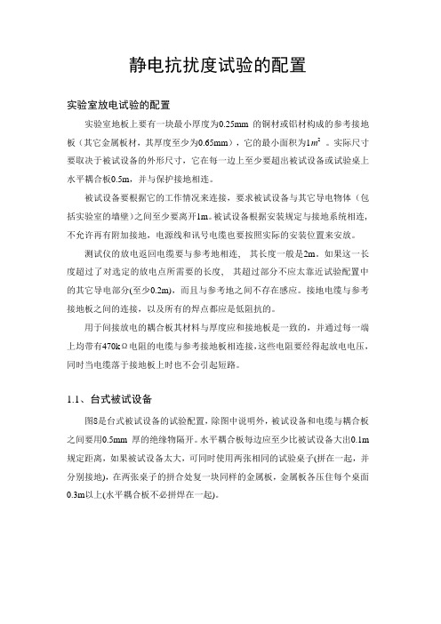
静电抗扰度试验的配置
实验室放电试验的配置
实验室地板上要有一块最小厚度为0.25mm 的铜材或铝材构成的参考接地板(其它金属板材,其厚度至少为0.65mm),它的最小面积为1m2。
实际尺寸要取决于被试设备的外形尺寸,它在每一边上至少要超出被试设备或试验桌上水平耦合板0.5m,并与保护接地相连。
被试设备要根据它的工作情况来连接,要求被试设备与其它导电物体(包括实验室的墙壁)之间至少要离开1m。
被试设备根据安装规定与接地系统相连, 不允许再有附加接地,电源线和讯号电缆也要按照实际的安装位置来安放。
测试仪的放电返回电缆要与参考地相连, 其长度一般是2m。
如果这一长度超过了对选定的放电点所需要的长度, 其超过部分不应太靠近试验配置中的其它导电部分(至少0.2m),而且与参考地之间不存在感应。
接地电缆与参考接地板之间的连接,以及所有的焊点都应是低阻抗的。
用于间接放电的耦合板其材料与厚度应和接地板是一致的,并通过每一端上均带有470kΩ电阻的电缆与参考接地板相连接,这些电阻要经得起放电电压,同时当电缆落于接地板上时也不会引起短路。
1.1、台式被试设备
图8是台式被试设备的试验配置,除图中说明外,被试设备和电缆与耦合板之间要用0.5mm 厚的绝缘物隔开。
水平耦合板每边应至少比被试设备大出0.1m 规定距离,如果被试设备太大,可同时使用两张相同的试验桌子(拼在一起,并分别接地),在两张桌子的拼合处复一块同样的金属板,金属板各压住每个桌面0.3m以上(水平耦合板不必拼焊在一起)。
图8台式被试设备的试验配置。
cs抗扰度测试标准和方法
cs抗扰度测试标准和方法
CS抗扰度测试是指对计算机系统进行抗扰度性能评估的一种测试方法。
以下是常见的CS
抗扰度测试标准和方法:
1. 标准:常见的标准包括IEEE Std 2136-2015《计算机系统可靠性评估》和MIL-STD-810《美
国国防部试验方法标准》。
2. 方法:
a. 温度变化测试:通过模拟温度变化对计算机系统进行测试,包括高温、低温和温度变化速
率等条件。
b. 湿度变化测试:模拟湿度变化对计算机系统的影响,包括高湿度、低湿度和湿度变化速率
等条件。
c. 振动测试:通过模拟不同频率和振幅的振动对系统进行测试,包括随机振动、正弦振动和
冲击振动等。
d. 冲击测试:模拟系统在受到突然冲击或碰撞时的抗冲击性能。
e. 电磁干扰测试:模拟不同频率和强度的电磁干扰对系统的影响,如电磁辐射抗扰度测试和
电磁感应抗扰度测试。
f. 电源变化测试:模拟电源电压波动、瞬时断电和频繁开关等条件对系统的影响。
g. 环境适应性测试:包括盐雾、尘埃、震动、太阳辐射等不同环境条件下对系统的影响。
h. 软件鲁棒性测试:通过模拟不同的输入数据和错误处理情况,测试系统的鲁棒性和容错性。
i. 长期可靠性测试:连续长时间进行测试,评估系统在长期运行中的抗扰度性能。
需要根据具体的测试需求和应用环境选择合适的测试标准和方法,以确保计算机系统在各种扰动条件下的可靠性和稳定性。
EMC试验报告范文

试品类型:oooo 试验时间:2013、4、1—2013、试验环境:20摄氏度4、2试验项目:静电放电抗扰度试验、振荡波抗扰度试验、快速瞬变脉冲群抗扰度试验、浪涌冲击抗扰度试验、电磁传导试验试验依据: Q/INP 001-2012 5.10.1.1JB/T 11067-2011 4.11.1.1试验概况:实验结论:抗扰度试验判据说明:序号判定准则类别说明1 判据A 试验中装置在规范极限值内性能正常2 判据B 试验中装置功能或性能暂时降低或丧失,但能自行恢复3 判据C 试验中装置功能或性能暂时降低或丧失,但需操作者干预或系统重调(或复位)4 判据D 试验中装置因装置(或元件)损坏而不可恢复的功能降低或丧失试验产品试验项目依据标准Q/INP 001-2012 5.10.1.1 B/T 11067-2011 4.11.1.1测试仪器3CTEST ESD-20G试验条件温度 20 ℃,湿度:正常,大气压:正常。
电磁条件保证受试设备正常工作,并不影响试验结果。
设备状态试验前设备可以正常工作,实验过程中,设备受到干扰信号后还可以继续工作。
试验等级接触放电:试验电压6kV;气隙放电:试验电压8kV;要求符合性能判据: B 。
试验布置严格按标准要求。
试验过程接触放电:对装置可接触的导电表面、螺钉、端口等金属体进行接触放电,分别选择4个以上试验点进行(每点至少50次,正负极性各25次),试验电压6kV,用尖端接触放电枪头,最大放电重复频率为1次/s。
试验电压应从最小值逐渐增加至规定的试验值,以确定故障的临界值。
气隙放电:对装置可接触的壳体表面,按键、指示灯、显示屏、壳体等的缝隙进行空气放电,分别选择3个以上试验点,每点进行至少20次单次放电,正负极性各10次,试验电压8kV,用圆形空气放电枪头。
试验电压应从最小值逐渐增加至规定的试验值,以确定故障的临界值。
设备表现试验框图:静电发生器的连接框图试验图片:图接触放电运行界面图气隙放电运行界面试验产品试验项目依据标准Q/INP 001-2012 5.10.1.1 B/T 11067-2011 4.11.1.1测试仪器试验条件温度 20 ℃,湿度:正常,大气压:正常。
抗扰度试验

2008-10-7 2008- 10-
BIMT Xiaoxiao
7
试验结果判定
若专业标准化技术委员会或产品技术规范没有给 出不同的技术要求,试验结果应该按受试设备的 运行条件和功能规范进行如下分类:
– 1) 在技术要求限值内的性能正常; – 2) 功能或性能暂时降低或丧失,但能自行恢复; – 3) 功能或性能暂时降低或丧失,但要求操作人员干预 或系统复位; – 4) 因设备(元件)或软件的损坏或数据的丢失而造成不能 自行恢复至正常状态的功能降低或丧失。
2008-10-7 2008- 10-
BIMT Xiaoxiao
19
射频电磁场辐射抗扰度试验
GB/T 17626.2 GB/T 17626.3 GB/T 17626.4 GB/T 17626.5 GB/T 17626.6 GB/T 17626.8 GB/T 17626.11
试验要求
– 用1kHz的正弦波对未调制信号进行80%的 幅度调制
BIMT Xiaoxiao
13
静电放电抗扰度试验
GB/T 17626.2 GB/T 17626.3 GB/T 17626.4 GB/T 17626.5 GB/T 17626.6 GB/T 17626.8 GB/T 17626.11
试验布置
2008-10-7 2008- 10-
BIMT Xiaoxiao
GB/T 17626.2 GB/T 17626.3 GB/T 17626.4 GB/T 17626.5 GB/T 17626.6 GB/T 17626.8 GB/T 17626.11
试验布置
2008-10-7 2008- 10-
BIMT Xiaoxiao
25
YY0505中引用的抗扰度标准
UCS 500N5 UCS 500N7系列抗扰度综合测试仪中文手册
3.1. 前面板.........................................................................................................7 3.2. 后面板.........................................................................................................9
产品手册 - USC500 系列抗扰度综合测试
UCS 500 系列抗扰度综合测试仪
中文操作手册
总部地址: 北京市海淀区学清路 9 号汇智大厦 A 座 605 室 邮编:100085 电话:010-82732992 传真:010-82732995
南京办事处: 洪武路 359 号福鑫国际大厦东座 2507 室
7.4.1. 工厂校准 .............................................................................................. 28 7.4.2. EMTEST 仪器校准周期指导 ....................................................................... 28
8. 交付件 ............................................................................................................. 29
8.1. 基本设备 .................................................................................................... 29 8.2. 附件和选件 ................................................................................................. 29
信息技术设备抗扰度限值和测量方法
信息技术设备抗扰度限值和测量方法1.信息技术设备应具有一定的抗扰度,能够在一定范围内抵御外部干扰。
Information technology equipment should have a certain anti-jamming ability to resist external interference within a certain range.2.抗扰度限值是指设备在正常工作条件下所能承受的干扰程度的上限。
The anti-jamming limit refers to the maximum level of interference that the equipment can withstand under normal working conditions.3.为了评估设备的抗扰度,需要制定相应的测量方法和标准。
In order to evaluate the anti-interference of the equipment, corresponding measurement methods and standards need to be established.4.测量方法应该能够客观地反映设备在受到干扰时的表现。
The measurement method should objectively reflect the performance of the equipment when subjected to interference.5.常见的抗扰度测量方法包括电磁兼容性测试、干扰抑制比测试等。
Common anti-jamming measurement methods include electromagnetic compatibility testing and interference suppression ratio testing.6.电磁兼容性测试可以评估设备在电磁环境中的抗扰度。
传导骚扰抗扰度(CS)测试

传导骚扰抗扰度(CS)1.传导骚扰抗扰度1.1传导骚扰抗扰度概述本标准主要介绍国际标准IEC61000-4-6:2006,对应国家标准GB/T17626.6:1998《电磁兼容试验和测量技术射频场感应的传导骚扰抗扰度》的试验方法。
1.2传导骚扰抗扰度试验目的和应用场合本标准所涉及的主要骚扰源是来自9kHz~80MHz频率范围内射频发射机产生的电磁场。
该电磁场会作用于电气、电子设备的电源线、通信线和接口电缆等连接线路上,这些连接引线的长度则可能与干扰频率的几个波长相当,因此,这些引线就变成被动天线,接受外界电磁场的感应,引线电缆就可以通过传导方式耦合外界干扰到设备内部(最终以射频电压和电流所形成的近场电磁骚扰到设备内部)对设备产生干扰。
从而影响设备的正常运行。
所以,本标准的目的主要是建立一个评估射频场感应的传导骚扰抗扰度性能的公共参考,为有关产品的专业技术委员会或用户和制造商提供一个基本参考。
2传导骚扰抗扰度常见术语2.1人工手模拟正常工作条件下,手持式电气设备和地之间的人体阻抗的电网络2.2辅助设备为受试设备正常运行提供所需信号的设备和检验受试设备性能的设备。
2.3注入钳u 电流钳由被注入信号的电缆构成的二次绕组实现的电流变换器。
u 电磁钳由电容和电感耦合相组合的注入装置。
2.4共模阻抗在某一端口上共模电压和共模电流之比。
2.5耦合系数在耦合装置的受试设备端口所获得的开路电压(电动势)与信号发生器输出端上的开路电压的比值2.6耦合网络以规定的阻抗从一电路到另一电路传输能量的电路。
2.7去耦网络防止施加给受试设备的测量信号影响不被测量的其他装置、设备或系统的电路。
2.8电压驻波比沿线最大电压和邻近最小电压幅度之比。
3传导骚扰抗扰度试验等级u 在9kHz~150kHz频率范围内,对来自射频发射机的电磁场所引起的感应骚扰不要求测量。
u 在150kHz~80MHz频率范围内,对来自射频发射机的电磁场所引起的感应骚扰的抗扰度试验应根据设备和电缆最终安装时所处电磁环境按下面表格选择相应的试验等级。
常用产品抗扰度标准和测试方法
常用产品抗扰度度准和测试方法第一章、静电放电抗扰度度试验静电放电抗扰度度试验为国际标准为GB/T17626.2(等同于国标标准IEC61000-4-2)。
第一节:静电的产生与危害静电放电是一种自然现象,当两种不同介电强度的材料相互磨擦时,就会产生静电电荷,当其中一种材料上的静电电荷积累到一定程度,在与另外一个物体接触时,就会通过这个物体到大地的阻抗而进行放电。
静电放电及影响是电子设备的一个主要干扰源。
由于静电的存在,使人体成为对电子设备或爆炸性材料的最大危害。
电子工程师们发现,静电放电多发生于人体接触半导体器件的时候,有可能导致数层半导体材料的击穿,产生不可挽回的损坏。
静电放电及紧跟其后的电磁场变化,可能危害电子设备的正常工作。
第二节:静电放电试验和放电方式静电放电抗扰度试验模拟了两种情况:1)设备操作人员直接接触摸设备时对设备的放电,和放电对设备工作的影响;2)设备操作人员在触摸邻近设备时,对所关心的这台设备的影响。
其中1)称为直接放电,2)称为间接放电静电放电可能造成的后果是:1)通过直接放电,引起设备中半导体的损坏,从而造成设备的永久性失效。
2)由放电而引起的近场电磁场变化,造成设备的误动作。
静电放电方式:静电放电试验有直接和间接两种。
标准(IEC61000-4-2/GB/T17626.2)规定直接放电以接触放电为首选方式,只有在不能用接触放电的地方才改用气隙放电。
对间接放电,标准中是用金属板来模拟被试设备附近的放电物体。
由于是金属板,对间接放电无一例外采用接触放电为首选的放电方式。
第三节 静电放电发生器技术指标3.1 主要技术指标3.1.1 静电电压电压极性:正、负最大放电电压:±30.00kV分辨率: 0.001kV (0.000kV ~9.999kV ),0.01kV (10.00kV ~30.00kV )3.1.2 放电计数当放电间隔大于等0.1秒时计数范围为:1~9999,当放电间隔小于0.1 秒时计数范围为:1~100;3.1.4IEC 波形参数IEC 典型电流波形4.1.5 放电方式手动:按一下放电模块的触发按键或放电枪的枪机,进行一次放电;自动:按照设定的放电间隔(0.050s~9.999s)连续放电;注:速度快于10次/秒的自动放电应尽量少用,尤其是在10kV以上高压下,否则会影响仪器的使用寿命。
电子产品电磁兼容抗扰度测试培训资料

2、施加方式
在规定场强下,按照一定的扫频要求(1%)对 试品进行全频段(80M-1GHz)的辐射干扰测试
干扰对策
1、良好的屏蔽和接地 2、注意部分易引入感应干扰的器件和电
路的处理
射频传导抗扰度测试
标准:GB/T17626.6 IEC61000-4-6
试验目的:考核电子产品抵抗射频电磁场传 导干扰的能力。该干扰的来源一般是 9kHz~80MHz的射频发射机。
测试等级
2、阻尼振荡波试验等级
试验等级 1 2 3 4 X
X为开放等级
共模电压 KV 0.5 1 2 --X
变电站产品为 2.5KV
差模电压KV1 0.25 0.5 1 --X
振铃波干扰特性
阻尼振荡波干扰特性
衰减振荡波试验布置示例(立式设备)
车载电子设备抗扰度测试
标准:ISO7637-2:2004 P1波形:用于模拟由于在电感性负载上切断电源时产生的瞬变,可用
试验方式: 1、共模干扰 2、差模干扰
浪涌(模拟雷电干扰)干扰特性
浪涌试验内容
试验配置
1、浪涌发生器 2、耦合去耦网络
配置示例
试验方法
1、试验等级
LEVEL
共模注入(KV) 差模注入(KV)
1
0.5
X
2
10Biblioteka 53214
4
2
2、施加方式
以共模或差模干扰形式实现试品电源每 相对地干扰测试,测试间隔1min,正负极 性测试次数各5次;
且不对该环境中的任何事物构成不能承受的电磁骚扰的 能力。可见任何电子设备的电磁兼容性均包含电磁发射 和电磁敏感度两方面。
二、电磁兼容标准
分析环境 中的各种 电磁干扰
寄存器的抗干扰能力与容错性实验

寄存器的抗干扰能力与容错性实验寄存器是计算机系统中一种重要的硬件组件,具有存储和处理数据的功能。
在计算机系统中,寄存器的抗干扰能力与容错性至关重要。
本文将介绍寄存器的抗干扰能力与容错性的实验,以及相关实验结果和数据分析。
一、实验目的本实验旨在验证和评估不同类型寄存器的抗干扰能力与容错性,并通过实验结果和数据分析,得出结论和优化建议。
二、实验材料和方法1. 实验材料:- 计算机系统- 不同类型的寄存器:D触发器、JK触发器、RS触发器等。
- 干扰源:电磁干扰设备、电源干扰等。
2. 实验方法:1) 准备实验环境:保证实验环境安静无杂音,排除其他干扰因素。
2) 连接实验设备:将不同类型的寄存器与计算机系统连接,确保连接稳定。
3) 设置实验参数:对不同类型的寄存器进行参数设置,包括输入信号频率、信号强度等。
4) 施加干扰信号:使用干扰源施加不同强度的干扰信号。
5) 采集数据:通过计算机系统对寄存器进行数据采集和记录。
6) 数据分析:对采集的数据进行分析,评估寄存器的抗干扰能力与容错性。
7) 结果和结论:根据实验数据和分析结果得出结论,并提出优化建议。
三、实验结果和数据分析在实验中,我们选取了不同类型的寄存器进行抗干扰能力和容错性实验,并采集了相应的数据进行分析。
1. D触发器实验结果:- 施加强干扰信号后,D触发器的稳定性较差,容易出现数据错误。
- 干扰信号强度越大,D触发器的容错性越低。
2. JK触发器实验结果:- JK触发器相比D触发器具有更好的抗干扰能力,即使在强干扰信号下,数据错误的概率较低。
- JK触发器具有良好的容错性能,在一定程度上可以自动纠正干扰引起的数据错误。
3. RS触发器实验结果:- RS触发器的抗干扰能力相对较差,在强干扰信号下容易产生数据错误。
- RS触发器的容错性较低,无法自动纠正干扰引起的数据错误。
四、结果和结论通过对不同类型寄存器的抗干扰能力与容错性实验及数据分析,我们得出以下结论:1. D触发器在强干扰信号下容易出现数据错误,抗干扰能力相对较弱。
LabVolt系列抗干扰 receiving 训练和测量系统582074 (8092-00)说明书
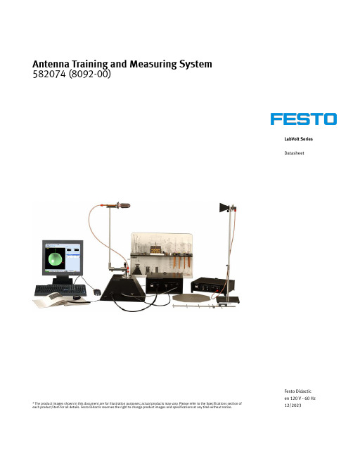
LabVolt SeriesDatasheet Antenna Training and Measuring System582074 (8092-00)* The product images shown in this document are for illustration purposes; actual products may vary. Please refer to the Specifications section of each product/item for all details. Festo Didactic reserves the right to change product images and specifications at any time without notice.Festo Didactic en 120 V - 60 Hz 12/2023Antenna Training and Measuring System, LabVolt SeriesTable of ContentsGeneral Description_________________________________________________________________________________3 Antennas_________________________________________________________________________________________5 Features & Benefits_________________________________________________________________________________7 List of Equipment___________________________________________________________________________________7 List of Manuals____________________________________________________________________________________7 Table of Contents of the Manual(s)____________________________________________________________________8 Equipment Description______________________________________________________________________________8Antenna Training and Measuring System, LabVolt SeriesGeneral DescriptionThe Antenna Training and Measuring System (ATMS) provides teachers and students with training materials for hands-on experimentation on antennas in the 1 GHz and 10 GHz bands. A convenient and powerful antenna measuring system, the ATMS can also be utilized by design and research teams.The complete Antenna Training and Measuring System includes a set of 1 GHz antennas, a set of 10 GHz antennas, an RF Generator, a receiving system, and the Data Acquisition and Management Software for Antennas (LVDAM-ANT), a user-friendly software operating under the Microsoft® Windows™ environment. The receiving system consists of a rotating Antenna Positioner linked to a Data Acquisition Interface connected to the USB port of a personal computer.The system is designed for low power operation, both in the 1 GHz and 10 GHz bands (specifically at 915 MHz and at 10.5 GHz), allowing measurements of antenna characteristics in these bands. The data acquisition interface controls the antenna positioner and acquires the received antenna signal.The LVDAM-ANT package provides a toolbox for controlling antenna rotation and data acquisition, as well as for displaying measured antenna characteristics in the E and the H planes. It also includes algorithms for estimating beamwidth and antenna gain from measurements or from external data.The ATMS is a self-contained, stand-alone system that does not require other microwave equipment. However, optional antennas, a two element phasing kit, and a set of RCS demonstration accessories can be added to the ATMS in order to enhance the scope of experimentation on antennas and reflectors. These pieces of optional equipment are listed and described in the Optional Equipment and Optional Equipment Description sections of this data sheet. Furthermore, the ATMS is compatible with the 10.5 GHz Microwave Technology Training System, Model 8090. The VSWR Meter and the Power Meter of the Microwave Technology Training System, along with microwave components such as the slotted line, the Gunn oscillator, attenuators, and couplers, can be put to use for various creative laboratory projects.Figure 1. The E-plane and the H-plane patterns are acquired separately. Thesepatterns can be plotted on a polar graph (as shown in figure) or a Cartesiangraph (see Figure 2).Antenna Training and Measuring System, LabVolt SeriesFigure 2. E- and H-plane patterns of an helical antenna plotted on a Cartesiancoordinate graph.Figure 3. The acquired E- and H-plane patterns can be displayed simultaneouslyon a tri-dimensional (3D) display (shown in figure: dipole antenna pattern).Figure 4. The acquired E- and H-plane patterns can be displayed simultaneouslyon a tri-dimensional (3D) display (shown in figure: helical antenna pattern).Antenna Training and Measuring System, LabVolt SeriesFigure 5. The E- and H-plane patterns can also be combined to produce a full 3D radiation pattern (shown in figure: dipole antenna pattern).•••••••••••••AntennasThe ATMS provides a great variety of 1-GHz and 10-GHz antennas. With the exception of the horn- andwaveguide-type antennas, connection to each antenna is made through an SMA connector. The 1-GHz and 10-GHz antennas available in the ATMS are listed below:1-GHz Antennas:Dipoles (λ/2, λ, 3λ/2)Folded DipoleFolded Dipole with BalunMonopole (over ground plane)Drooping MonopoleLoops (circular, square, lozenge)Fixed YagiAdjustable Yagi10-GHz Antennas:Open-Ended WaveguideSlotted Waveguide (single and multi-slots)Horns (small and large aperture)Helical (right-hand and left-hand circular polarization)Patch (rectangular, parallel-fed array, series-fed array)The following figures show polar plots of the radiation patterns of the folded dipole and slotted-waveguide antennas, obtained using the ATMS:Antenna Training and Measuring System, LabVolt SeriesFolded Dipole AntennaAntenna Training and Measuring System, LabVolt Series••••••••••Slotted-Waveguide AntennaFeatures & BenefitsConvenient and powerful antenna measuring system that can also be utilized by design and research teamsStand-alone system requiring no other microwave equipmentProvides system-level, hands-on experimentation on antennas in the 1-GHz and 10-GHz bands in the classroomRugged, high-quality components designed for hands-on training purposesConvenient and powerful antenna measuring system that can also be utilized by design and research teamsMeets a variety of needs and budgets because of options Does not require an anechoic chamberDevices and components fabricated from electroless-plated brass to standard X-band waveguide dimensionsWaveguide flanges are joined by precision quick fasteners, allowing rapid assembly and disassembly of microwave circuitsEstimated program duration: 45 hoursList of EquipmentQty Description Model number1Antenna Fundamentals (Student Manual) ___________________________________________ 580303 (30857-00)1Antenna Fundamentals (Instructor Guide) __________________________________________ 580310 (30857-10)1RF Generator __________________________________________________________________ 8095643 (9505-10)1Antenna Positioner ______________________________________________________________ 581819 (9506-00)1Data Acquisition Interface / Power Supply ___________________________________________ 581825 (9507-30)1Horn Antenna, Small Aperture _____________________________________________________ 581848 (9535-A0)2Horn Antenna, Large Aperture _____________________________________________________ 581852 (9550-00)2Helical Antenna, Right-Hand Circular Polarization _____________________________________ 581853 (9551-00)1Helical Antenna, Left-Hand Circular Polarization _______________________________________ 581854 (9552-00)1Patch Antennas _________________________________________________________________ 581855 (9553-00)1Slotted-Waveguide Antenna _______________________________________________________ 581856 (9554-00)1Open-Ended Waveguide Antenna ___________________________________________________ 581857 (9555-00)1Yagi Antenna ___________________________________________________________________ 581860 (9560-00)1Wire Antennas __________________________________________________________________ 581861 (9561-00)1Cables and Accessories __________________________________________________________ 581914 (9594-10)1Waveguide Accessories __________________________________________________________ 581912 (9594-A0)1Antenna Support ________________________________________________________________ 581915 (9595-00)1Storage Module _________________________________________________________________ 581918 (9598-00)1IEC Power Cable, straight - NEMA (Type B) __________________________________________ 789405 (95451-00)List of ManualsDescriptionManual numberAntenna Fundamentals (Workbook) ___________________________________________________580303 (30857-00)Antenna Fundamentals (Workbook (Instructor)) __________________________________________580310 (30857-10)Data Acquisition and Management Software (User Guide) _________________________________580315 (30857-E0)Antenna Training and Measuring System, LabVolt Series••••••••••••Table of Contents of the Manual(s)Antenna Fundamentals (Workbook) (580303 (30857-00))1-1 Radiation Pattern of a λ/2 Dipole at 1 GHz 1-2 Radiation Pattern of an Open Waveguide at 10 GHZ 1-3 Gain of Pyramidal Horn Antennas 1-4 Experiments with λ/2, λ, and 3λ/2 Dipoles 1-5 Half Wave Folded Dipole Antennas and Impedance Transformation with Baluns 2-1 Monopole Antennas 2-2 Loop Antennas 2-3 Circular Polarization and Helical Antennas 2-4 Parasitic Array (Yagi-Uda) Antennas 3-1 Antenna Arrays: The Slot Antenna 3-2 Microstrip Technology: The Rectangular Patch Antenna 3-3 Microstrip Planar Array AntennasEquipment DescriptionRF Generator8095643 (9505-10)The RF Generator contains two independent generators capable of producing a CW or 1 kHz square wave AM modulated RF signal at 915 MHz and 10.5 GHz. Each generator has a push-button switch for turning RF power on and off, a LED that flashes on and off when RF power is turned on, and an SMA output connector. The oscillator in the 915 MHz generator can be tuned from 800 to 1200 MHz via an external tuning voltage input. All outputs are fully protected against short-circuits and misconnections. The RFGenerator is self-powered and has a standard unregulated dc power bus to supply power to other compatible modules through its top panel connector. The unit beeps when RF power is turned on to help avoid interference and to warn students in the laboratory that RF power is emitted.SpecificationsParameterValuePower Requirement Current1 AService InstallationStandard single-phase ac outletUnregulated DC Output (Power Bus)+25 V typ. – 1 A max.; -25 V typ. – 1 A max.; +11 V typ. – 1 A max.1 GHz RF Power Output Impedance 50 ΩPower Level+5 dBm (typical); 0 dBm (minimum)Attenuation at reception Up to -59 dBm (49 dBm software controlled and 10 dBm with included physical attenuator)10 GHz RF Power Output Impedance 50 ΩPower Level+12 dBm (typical)Attenuation at reception Up to -59 dBm (49 dBm software controlled and 10 dBm with included physical attenuator)1 GHz Tuning Voltage Input Voltage Range 0-10 V Frequency Range 800-1200 MHz Protection AC Line InputCircuit breaker Unregulated DC Power Bus Circuit breaker Physical CharacteristicsAntenna Training and Measuring System, LabVolt SeriesParameter ValueDimensions (H x W x D)112 x 330 x 300 mm (4.4 x 13.0 x 11.8 in)Net Weight 6.1 kg (13.4 lb)Antenna Positioner581819 (9506-00)The Antenna Positioner consists of the mast for the receivingantenna (antenna under test), a drive motor, a signal detector, avariable attenuator, and a shaft encoder. The drive motor is usedto rotate the mast while the rotation is controlled by the LVDAM-ANT software via the Data Acquisition Interface. An SMAconnector, mounted on the base of the mast, allows aconnection to be made between the receiving antenna and thesignal detector. This detector provides a signal whose voltagedepends on the level of the RF signal received. This signal isavailable on a BNC connector for connection to the Data Acquisition Interface.The variable attenuator allows adjustments to be made to the sensitivity of the receiving system according to the strength of the received signal, in order to prevent system saturation. This attenuator is controlled by the LVDAM-ANT software via the Data Acquisition Interface. The shaft encoder is coupled with the shaft of the drive motor and provides signals to monitor the rotation of the mast. Two multi-pin connectors on the Antenna Positioner allow connection to the Data Acquisition Interface / Power Supply.SpecificationsParameter ValueUnregulated DC Power Requirement+25 V – 90 mA, -25 V – 90 mA, +11 V – 90 mADrive Motor Power Input24 V – 1.25 A – ACRF DetectorFrequency Range1-15 GHzInput Impedance50 ΩMaximum Input Power100 mW, CWSignal Amplifier InputImpedance10 kΩCenter Frequency 1 kHzSignal OutputVoltage Range0 to +10 VCenter Frequency600 ΩRange of rotationRange per acquisition0° to 360°Total range0° to infinity (rotary joint: no reel back required)Physical CharacteristicsDimensions (H x W x D)260 x 385 x 250 mm (10.2 x 15.2 x 9.8 in)Net Weight10.2 kg (22.4 lb)Antenna Training and Measuring System, LabVolt SeriesData Acquisition Interface / Power Supply 581825 (9507-30)The Data Acquisition Interface links the Antenna Positioner with the personal computer that runs the LVDAM-ANT software. The link to the computer is achieved through a USB port connector mounted on the rear panel of the module. The Data Acquisition Interface converts the received signal coming from the Antenna Positioner into a digital signal which can be used by thecomputer. It also routes the shaft encoder signals coming from the Antenna Positioner to the computer and provides the signals required to control the drive motor and the variable attenuator inthe Antenna Positioner. A BNC connector and a multi-pin connector allow connection of the Data Acquisition Interface to the Antenna Positioner.ManualDescriptionManual numberData Acquisition and Management Software (User Guide) _________________________________580315 (30857-E0)SpecificationsParameterValuePower Requirements Current1.5 AService Installation Standard single-phase ac outletData Acquisition Interface Analog Signal Input Voltage Range 0 to +2.5 V Analog Signal Input Impedance 1 MΩPower SupplyUnregulated DC Power Bus Output +25 V typ. – 1 A max.; -25 V typ. – 1 A max.; +11 V typ. – 1 A max.Drive Motor Power Output 24 V – 1.5 A – ACComputer Requirements A currently available personal computer running under one of the following operating systems: Windows ® 7 or Windows ® 8.Physical Characteristics Dimensions (H x W x D)167 x 330 x 300 mm (6.6 x 13.0 x 11.8 in)Net Weight8.5 kg (18.8 lb)Horn Antenna, Small Aperture 581848 (9535-A0)The Horn Antenna, Small Aperture is a WR90 waveguide-type pyramidal horn antenna.SpecificationsParameter ValueAntennaGain13.8 dBFrequency10.525 GHzHorn Antenna, Large Aperture581852 (9550-00)The Horn Antenna, Large Aperture is a WR90 waveguide-typepyramidal horn antenna.SpecificationsParameter ValueAntennaGain16.7 dBFrequency10.525 GHzHelical Antenna, Right-Hand Circular Polarization581853 (9551-00)The Helical Antenna, Right-Hand Circular Polarization is a helicalantenna with SMA connector. The antenna is protected with aplexiglass dome.SpecificationsParameter ValueAntennaGain13.6 dBFrequency10.525 GHzAxial Ratio 1.08Helical Antenna, Left-Hand Circular Polarization581854 (9552-00)The Helical Antenna, Left-Hand Circular Polarization is a helicalantenna with SMA connector. The antenna is protected with aplexiglass dome.SpecificationsParameter ValueAntennaGain13.6 dBFrequency10.525 GHzAxial Ratio 1.08Patch Antennas581855 (9553-00)The Patch Antennas set consists of three microstrip patchantennas with SMA connector that operate at a frequency of10.525 GHz.SpecificationsParameter ValueAntenna GainPatch (Rectangular)7.7 dBPatch (Series-Fed Array)13.0 dBPatch (Parallel-Fed Array)14.0 dBAntenna Frequency10.525 GHzSlotted-Waveguide Antenna581856 (9554-00)The Slotted-Waveguide Antenna is a light-weight, small-sizeWR90 waveguide-type slotted antenna. The slot antenna is ofthe "standing wave array" type. The array is terminated by ashort circuit at the end of the waveguide.SpecificationsParameter ValueAntennaGain13.2 dBFrequency10.525 GHzOpen-Ended Waveguide Antenna581857 (9555-00)The Open-Ended Waveguide Antenna is of the WR90 type.SpecificationsParameter ValueAntennaGain TBEFrequency10.525 GHzYagi Antenna581860 (9560-00)The Yagi Antenna is a six-element Yagi-Uda parasitic-arrayantenna with SMA connector.SpecificationsParameter ValueAntennaGain TBEFrequency 1 GHzWire Antennas581861 (9561-00)The Wire Antennas is a kit that consists of an active element anda set of parasitic elements which can be assembled to obtainvarious types of antennas (e.g. Yagi antenna, loop antenna,folded-dipole antenna, dipole antenna).SpecificationsParameter ValueAntenna GainDipole (λ/2) 1.9 dBFolded Dipole with Balun 2.1 dBMonopole (Over Ground Plane) 2.5 dBDrooping Monopole 1.6 dBCircular Loop 2.9 dBSquare Loop 2.9 dBLozenge Loop 2.9 dBCables and Accessories581914 (9594-10)The Cables and Accessories package contains the various cablesand accessories required to perform the exercises in theprogram training manuals. The accessories package contains thefollowing parts: three different lengths of coaxial cablesterminated with BNC connectors, whip, pigtail, and folded dipoleantennas, BNC T-connectors, resistive loads with BNCconnectors, headset. These accessories come in a convenientplastic storage case.Waveguide Accessories581912 (9594-A0)The Waveguide Accessories kit contains the accessoriesrequired when using the horn- and waveguide-type antennas ofthe ATMS. The kit includes quick-lock fasteners, waveguide-to-coaxial cable adapters (SMA connector), a waveguide plasticholder, a waveguide short-circuit, and copper tape to modify thecharacteristics of the slotted waveguide and patch antennas.Antenna Support581915 (9595-00)The Antenna Support is used as a mount for the fixed(transmitting) antenna of the ATMS. It comes with differentadapters to mount different types of antennas.Storage Module581918 (9598-00)The Storage Module consists of a storage cabinet for storingequipment included in the Antenna Training and MeasuringSystem.IEC Power Cable, straight - NEMA (Type B)789405 (95451-00)One side designed as a connector and one side with a country-specific plug (Type B).This power cord connects the equipment to a wall outlet.NEMA 5-15 for US, CA, Central America, BR, CO, EC, KR, TW, TH,PH, JP.Reflecting the commitment of Festo Didactic to high quality standards in product, design, development, production, installation, and service, our manufacturing and distribution facility has received the ISO 9001 certification.Festo Didactic reserves the right to make product improvements at any time and without notice and is not responsible for typographical errors. Festo Didactic recognizes all product names used herein as trademarks or registered trademarks of their respective holders. © Festo Didactic Inc. 2023. All rights reserved.Festo Didactic SERechbergstrasse 373770 DenkendorfGermanyP. +49(0)711/3467-0F. +49(0)711/347-54-88500Festo Didactic Inc.607 Industrial Way WestEatontown, NJ 07724United StatesP. +1-732-938-2000F. +1-732-774-8573Festo Didactic Ltée/Ltd675 rue du CarboneQuébec QC G2N 2K7CanadaP. +1-418-849-1000F. +1-418-849-1666。
NSG 4060低频抗干扰测试系统说明书

LOW FREQUENCY IMMUNITY TEST SYSTEMNSG 4060The NSG 4060 is an EMC immunity test system for the frequency range 15 Hz to 150 kHz. It consists of a sine wave generator, power amplifier, EUT monitoring interfaces and different coupling units depending on the application, i. e. NSG 4060-1 for testing IEC / EN 61000-4-16 including short duration disturbance tests for DC, AC from 162/3 Hz to 200 Hz and test levels up to 300 V. Voltage testing according IEC / EN 61000-4-19 requires the combination with CDND M316-2. It includes the differential mode coupling and decoupling and the required 10 Ω impedance of the disturbance source. Current testing according IEC / EN 61000-4-19, e.g. testing electricity meters, requires the combination with CT 419-5.The powerful and easy to use firmware makes the NSG 4060 independent from an external PC and control software, however it can also be remote controlled for system operation. Part of NSG 4060’s delivery is an USB-to-serial /optical converter which offers potential free remote control.Signal generator and integrated power amplifier 15 Hz to 150 kHz Meets IEC / EN 61000-4-16 in combi-nation with NSG 4060-1Meets IEC / EN 61000-4-19 in combi-nation with CDND M316-2 for volt-age and CT 419-5 for current testing Meets IEC / EN 60255-26 Annex A in combination with CN 60255-26 Prepared test configurations for IEC / EN 61000-4-16 and IEC / EN 61000-4-19 5.7” color displayMultiple EUT monitoring optionsNSG 4060 and NSG 4060-1 ExtensionUnit5.7“ color display,easy to use firmwareLOW FREQUENCY IMMUNITY TEST SYSTEMNSG 4060Technical specifications NSG 4060 in combination with NSG 4060-1Technical specifications NSG 4060 in combination with CDND M316-2Firmware: Select equipment menuFirmware: Sweep menuFirmware: During sweep testingLOW FREQUENCY IMMUNITY TEST SYSTEMNSG 4060Technical specifications NSG 4060 in combination with NSG 4060-1 hardware version 1A and connected CN 60255-26Technical specifications NSG 4060 in combination with CT 419-5LOW FREQUENCY IMMUNITY TEST SYSTEMNSG 4060General specifications NSG 4060-1 Extension UnitGeneral specifications NSG 4060LOW FREQUENCY IMMUNITY TEST SYSTEMNSG 4060View to the back plane of NSG 4060-1 Extension Unit(connected to NSG 4060)Ground(connected to NSG 4060)LF input from NSG 4060Output (connected to coupling network)Technical specifications NSG 4060 in combination with NSG 4060-1 4) and NSG 4060-op1Mechanical specifications NSG 4060-op1NSG 4060LOW FREQUENCY IMMUNITY TEST SYSTEMApplication rangeNote 1: Included in NSG 4060-1 Extension UnitNote 2: In combination with the coupling network / current transformerNote 3: Max. 2 ANote 4: Requires NSG 4060-1 with hardware version 1A (manufacture date after June 2016)NSG 4060LOW FREQUENCY IMMUNITY TEST SYSTEMApplication range (continued)Note 1: Included in NSG 4060-1 Extension UnitNote 4: Requires NSG 4060-1 with hardware version 1A (manufacture date after June 2016)Delivery items for the NSG 4060 seriesNSG 4060: NSG 4060 main unit; RS232 cable (Nullmodem); USO 4013 (USB to serial / optical converter with 20 m optical cable); mains cable GB, CH, USA / JP, EU; LE 261 sensor cable, USB stick with Report Program; operating manualNSG 4060-1: NSG 4060-1 extension unit; LE 260 earth cable; 2x safety banana cable 25 cm; safety banana to BNC cable 160 cm; system control cables BNC and LE 262 with SUB-D-15NSG 4060LOW FREQUENCY IMMUNITY TEST SYSTEMApplication example for IEC / EN 61000-4-16 testing(if required)Application example for IEC / EN 61000-4-19 voltage testing Array to mainsLOW FREQUENCY IMMUNITY TEST SYSTEMNSG 4060Application example for IEC / EN 61000-4-19 current testingApplication example for IEC / EN 60255-26 Annex A testingLOW FREQUENCY IMMUNITY TEST SYSTEM NSG 4060Model No. and optionsProduct picture Product name DescriptionPart numberNSG 4060Low frequency immunity test system, 15 Hz to 150 kHz generator,3 Hz to 10 kHz modulator, EUT monitoring ports, 600 W ampli-fier, 5.7” color display, 3 HU rack version, combined with optionNSG 4060-1 for IEC / EN 61000-4-16, combined with option CDNDM316-2 for IEC / EN 61000-4-19 voltage testing, combined withoption CT 419-5 for IEC / EN 61000-4-19 current testing255500NSG 4060Low frequency immunity test system, 15 Hz to 150 kHz generator,3 Hz to 10 kHz modulator, EUT monitoring ports, 600 W amplifier,5.7” color display, 3 HU desktop version, combined with optionNSG 4060-1 for IEC / EN 61000-4-16, combined with option CDNDM316-2 for IEC / EN 61000-4-19 voltage testing, combined withoption CT 419-5 for IEC / EN 61000-4-19 current testing255503NSG 4060-1Extension unit of NSG 4060 for IEC 61000-4-16 testing, provides50 Ω output impedance, short time testing and DC test function,3 HU rack version, incl. 2x cable banana, BNC/banana cable, LE260 earth cable, LE 262 system control cable, BNC system controlcable255501NSG 4060-1Extension unit of NSG 4060 for IEC 61000-4-16 testing, provides50 Ω output impedance, short time testing and DC test function, 3HU desktop version, incl. 2x cable banana, BNC/banana cable, LE260 earth cable, LE 262 system control cable, BNC system controlcable255504NSG 4060-op1External DC power source 2.4 KW255507 Option 4060-frontOption for NSG 4060, output located on front panel, factory fitted257095Option 4060-1-front Option for NSG 4060-1, LF input and LF output located on frontpanel, factory fitted257096NSG 4060-TC Traceable calibration (ISO17025) of NSG 4060 combined withNSG 4060-1 for IEC 61000-4-16, order only with the device97-255500NSG 4060-DAkkS DAkkS calibration (ISO17025) of NSG 4060 combined with NSG 4060-1 for IEC 61000-4-16, order only with the device98-255500 SW 4060Switch for combining NSG 4060, NSG 4060-1 and CDND M316-2,recommended for rack installations255505Teseq GmbHLandsberger Str. 255 · 12623 Berlin · GermanyT + 49 30 56 59 88 35 F + 49 30 56 59 88 34**********************LOW FREQUENCY IMMUNITY TEST SYSTEM NSG 4060© September 2016 Teseq ®Specifications subject to change without notice.Teseq ® is an ISO-registered company. Its productsare designed and manufactured under the strictquality and environmental requirements of the ISO9001. This document has been carefully checked.However, Teseq ® does not assume any liability forerrors or inaccuracies.82-255500 E05 September 2016Product picture Product nameDescriptionPart number Rack 4060-23H Rack 23 HU for NSG 4060, NSG 4060-1, CDND M316-2 and ITF 14,front panels, connectors and wheels included 257510Rack 4060-37H Rack 37 HU for NSG 4060, NSG 4060-1, CDND M316-2 and ITF 14,front panels, connectors and wheels included257511CDND M316-2Coupling Decoupling Network for IEC 61000-4-19 DM voltage, type M3 (M2), 16 A, bananaDatasheet: /products/CDND-series.php247757CDND 419-TC Traceable calibration (ISO17025) for IEC 61000-4-19 requirements, order only with NSG 4060 and CDND M316-297-247757CDND 419-DAkkS DAkkS accredited calibration (ISO17025) for IEC 61000-4-19requirements, order only with NSG 4060 and CDND M316-298-247757CT 419-5Current transformer, 1:1, 5 A for DM current IEC 61000-4-19Datasheet: /products/CT-series.php 255650CT 419-TC Traceable calibration (ISO17025) for IEC 61000-4-19 requirements, order only with NSG 4060 and CT 419-597-255650CT 419-DAkkSDAkkS accredited calibration (ISO17025) for IEC 61000-4-19requirements, order only with NSG 4060 and CT 419-598-255650。
计算机抗扰度实验报告

计算机抗扰度性能测试实验工物02 黄丽达2010011686同组姓名:李智试验时间:11.81.实验目的抗扰度性能是电子产品电磁兼容性能的一个重要方面。
抗扰度性能测试包括很多个测试项目,一般视具体产品而定,主要有静电放电、电快速脉冲群、雷击浪涌、工频磁场、电源跌落等等。
对常用的计算机进行抗扰度测试,可以了解计算机的抗扰度性能,了解干扰的来源和危害程度,便于我们正常使用,进而学习设计抗干扰的方法。
2. 实验设备●静电放电抗扰度试验系统组成:HAEFELAY PESD 1600空间耦合板本系统可以模拟实际操作时产生的静电放电,测试设备是否有充分的静电防护能力。
系统可以完成高达16.5kV的空气放电和9.0kV的接触放电测试。
●电快速脉冲群抗扰度试验系统组成:HAEFELAY PEFT 4010 耦合钳系统可以模拟由于感性负载开关过程而在公用电网中产生的电快速脉冲群,通过对受试设备施加该脉冲群就能评估受测设备的抗扰水平。
●电压暂降、短时中断和电压变化抗扰度试验系统组成:HAEFELAY PLINE 1610系统可以模拟电网突然由于故障或者大的负载变化而导致的电压暂降和短时中断,或者由于负载连续变化使电网电压产生波动,由此来评价受试设备对于这种现象的承受能力。
●工频磁场抗扰度试验系统组成:HAEFELAY MAG10 线圈本系统可以进行工频磁场的抗扰度试验。
系统能产生稳定持续的工频磁场,用以检测设备遭受到相关磁场时的抗扰度。
浪涌(冲击)抗扰度试验系统组成:HAEFELAY PSURGE 4010系统可以模拟由于雷击而感应到公用电网中产生的大电流、高电压信号,通过对受试设备施加该浪涌信号就可以评估出该设备的抗扰水平。
系统还可以完成非屏蔽不对称工作互连线、非屏蔽对称工作互连线/通信线、屏蔽线、施加电位差等抗扰度实验。
3.实验内容与记录3.1测试计算机的抗静电放电性能对计算机各个部位进行空气放电或接触放电,凡是金属部分都可以接触放电,注意观察计算机的反应,放电的电压由低到高慢慢增加,当计算机出现不可自己恢复的较为严重的现象时就不要再增加电压。
第九章 抗扰度试验—Part Two

图9-5 电压脉冲和电流脉冲波形图 (a) 开路电压波形; (b) 短路电流波形
图 9-6 波形发生器原理接线图 U—高压电源电压;Rc—充电电阻; Cc—储能电容;Rs1、Rs2—波长形成电阻; Rm—阻抗匹配电阻;Lm—阻抗匹配电感
�
IEC标准推荐的试验电源应具有以下参数 :
( 1 ) 开路输出电压:0.5 kV~4kV以上,误差±10%; 0.5kV ( 2 ) 短 路 输 出 电 流 : 0.25 kA ~ 2kA 以 上 , 误 差 0.25kA ±10%; ( 3 ) 发生器本身内阻:2Ω,附加电阻10~12Ω 或40~42Ω; ( 4 ) 极性:正极性和负极性; ( 5 ) 相位移:360° ( 6 ) 最大重复率:至少 l 次/min 。
协商决定xxxx5555025025025025555505050505111155550505050555551111222255551111555522223333555522222525252544444444重复率千次ssss峰值kvkvkvkvkvkvkvkv脉冲电压重复率千次ssss峰值脉冲电压在输入输出信号数据和控制端口等级在供电电源端口表98989898试验等级开路输出试验电压和脉冲的重复率五阻尼振荡试验?该试验的目的是检验电气或电子设备对由高压或中压网络中的有关现象在低压电路中感应的振荡瞬态的抗扰度
五、阻尼振荡试验
3级: 电缆平行敷设的电气环境,浪涌电压可能不 超过2kV。如公用配电电缆网络,工业过程区 域、变电所区域等。 4级: 互连线按户外电缆沿电源电缆敷设并且这些 电缆被作为电子和电气线路的电气环境。浪涌 电压可能达到4kV。如公用配电架空网络、未 受保护场所的高压变电站等。 5级: 在非人口稠密区电子设备与通信电缆以及架 空电力线路连接的电气环境。 X级: 产品技术要求中规定的特殊环境。 � 对于电源线和输入/输出,采用相同的试验等 级。
抗扰度
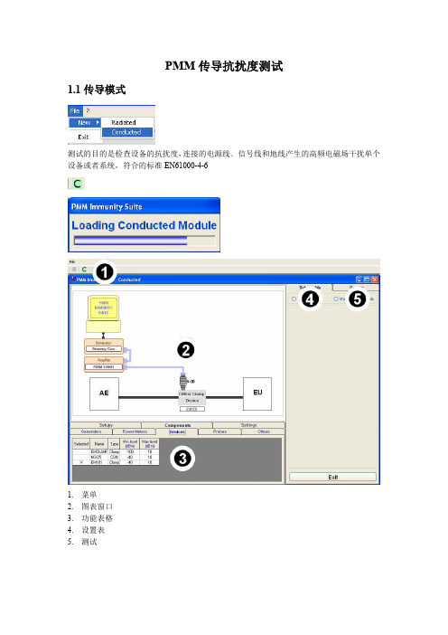
PMM传导抗扰度测试1.1传导模式测试的目的是检查设备的抗扰度,连接的电源线﹑信号线和地线产生的高频电磁场干扰单个设备或者系统,符合的标准EN61000-4-61.菜单2.图表窗口3.功能表格4.设置表5.测试1.2 EN61000-4-6设置登陆传导模式,选择设置-CDN/Clamp-Clamp+Probe1.3设备选择这个阶段选择使用设备(校准或者测试),软件按设备类型划分,双击点击相应的线使用设定的模式(1)信号发生器:清单列出可用信号发生器(2)功率计:清单列出可用信号功率计(3)设备:包括CDN和所有钳(4)电流探头(5)其他:显示功率放大器可以点击右键选择Add new增加新的设备点击相应的行可以检查﹑修改或取消设备。
-Modify :改变设备的参数:-Remove:删除设备和设备的驱动-Check Device :确定设备的驱动工作和设备的连接是否正常,这个选项只可检查选择的设备。
如果没有连接好将显示:如果设备的驱动没有安装将显示:请检查设备的连接和驱动安装,之后才能进行校准或者测试,如果是校准,程序将自动检查并导出错误的报告。
1.4图表窗口软件窗口将显示选择的设备:面板的底部打钩的设备将显示,可以双击选择或者更换选择的设备。
1.5设置在图解窗口执行设置,使用Measure设置校准参数Multiscan区域扫描可以在给定频率范围修改测量参数Break points断点表格设置,可以设置测试临时中断频率:当达到停止频率将显示预设提示:断点建在图标显示垂直条纹,点击OK继续测试。
Charts 修改视图,可以修改色彩,参考电平,参考电压等1.6设置管理新的测试,将默认导入文件CondDefault.tsc, 避免导入新的设置,可以保存单的.tsc.文件。
-File—Save setting覆盖使用的文档,如果在程序打开时没有导入文件,默认文件将被覆盖点击Yes覆盖使用的文件,选择NO将取消操作进入主窗口。
第九章 抗扰度试验
1. 低压供电网络中的低频骚扰 ( 考虑了三种类型的环境 )
( 1 ) 具有相对较低骚扰电平的公共 低压配电网络; ( 2 ) 具有相对较高骚扰电平的工业 低压配电网络; ( 3 ) 电站中的低压网络。
2. 瞬态和高频骚扰
这类骚扰的电平取决于: ( 1 ) 电磁骚扰源 ( 2 ) 安装条件,如屏蔽、接地、过电压 保护等。
五、抗扰度试验的分类
1. 低频骚扰的抗扰度试验; 2. 传导暂态和高频骚扰的抗扰度试验; 3. 静电放电的抗扰度试验; 4. 磁场骚扰的抗扰度试验; 5. 电磁骚扰的抗扰度试验; 6. 其它抗扰度试验。
六、环境条件
对于特定产品,有关试验和严酷度 等级的选择通常取决于环境条件。 在本条款的范围内,“环境条件” 包括电磁环境及安装条件。 由于这些影响的多样性,有必要为 各类骚扰定义特定的环境条件。
3. 为减少事故,提高二次设备的 抗骚扰能力,有必要对二次设 备进行抗扰度试验。 4. 抗扰度试验的目的是对处于电 磁骚扰影响下的二次设备的运 行情况进行检查。试验时设备 总处于供电状态并正常运转。
四、抗扰度试验的IEC标准的 适用范围:
IEC的产品委员会、用户及电力、 电子设备制造厂都规定了抗骚扰标 准和相应的抗扰度试验方法。 为了统一起见,TC-77拟制定一个 关于低压设备的抗骚扰标准。标准 根据被试设备的不同种类和使用条 件推荐适当的试验方法。
优先采用的电压变化所需时间和减 小后的电压维持时间由表9-5给出。 电压变化的速率应是常数,但电压 可是阶跃变化的,阶跃应定位在过 零附近,且不应大于10%UT,当阶 跃在1%UT以下,则可认为电压变 化速率是常数。 对EUT进行每一种规定的电压变化, 在最典型的运行方式下进行三次试 验,试验之间间隔10s。
电脑性能测试实验指导

《计算机硬件性能检测》实验指导书一、实验目的:1、熟练掌握通过测试软件在不拆机情况下了解计算机硬件参数信息及性能检测方法;2、掌握常用CPU、内存、显卡、硬盘、光驱等计算机性能指标。
3、了解计算机组装优选配件方法。
二、实验性质:验证性实验。
三、实验学时:4学时。
四、实验仪器和设备:1、硬件要求:计算机配置不低于:2.5GMHz的CPU、1GB内存、2GB可用硬盘空间、dvd光驱、LCD显示器。
2、软件要求安装Windows XP操作系统,预装下列计算机测试软件:1、CPU测试:Cpu-Z 1.54 、Hot CPU Tester Pro V4.412、内存测试:MemTest 4.03、显卡测试:3DMark 2005 Free Edition4、显示器测试:DisplayX 1.2 、Nokia Monitor Test 2.05、声卡测试:directX诊断工具、Right Mark Audio Analyzer6、硬盘测试:HD Tune 4.50 Pro7、光驱测试:Nero CD-DVD Speed V4.78、键鼠测试:PassMark KeyboardTest V3.09、计算机整机性能综合测试:EVEREST Ultimate Edition 5.50 Final 、鲁大师2.66五、实验内容:安装应用上述计算机测试软件对实验用计算机硬件性能全面检测。
六、实验步骤:1.计算机配件参数信息及检测。
1)使用Cpu-Z 1.54检测计算机CPU参数。
CPU-Z是一个检测CPU信息的免费软件,这些信息包括:CPU 名称、厂商、性能、当前电压、L1 L2 cache情况;内核进程;内部和外部时钟等。
支持全系列的Intel以及AMD品牌的CPU。
CPU-Z能提供全面的CPU相关信息报告,包括有处理器的名称、厂商、时钟频率、核心电压、超频检测、CPU所支持的多媒体指令集,并且还可以显示出关于CPU的L1、L2的资料(大小、速度、技术),支持双处理器。
- 1、下载文档前请自行甄别文档内容的完整性,平台不提供额外的编辑、内容补充、找答案等附加服务。
- 2、"仅部分预览"的文档,不可在线预览部分如存在完整性等问题,可反馈申请退款(可完整预览的文档不适用该条件!)。
- 3、如文档侵犯您的权益,请联系客服反馈,我们会尽快为您处理(人工客服工作时间:9:00-18:30)。
计算机抗扰度性能测试实验
一、实验目的
抗扰度性能是电子产品电磁兼容性能的一个重要方面。
抗扰度性能测试包括很多个测试项目,一般视具体产品而定,主要有静电放电、电快速脉冲群、雷击浪涌、工频磁场、电源跌落等等。
对常用的计算机进行抗扰度测试,可以了解计算机的抗扰度性能,了解干扰的来源和危害程度,便于我们正常使用,进而学习设计抗干扰的方法。
二、实验设备
●静电放电抗扰度试验
系统组成:(如图1)
HAEFELAY PESD 1600
空间耦合板
本系统可以模拟实际操作时产
生的静电放电,测试设备是否有充分
的静电防护能力。
系统可以完成高达
16.5kV的空气放电和9.0kV的接触放
电测试。
图1静电放电抗扰度测试系统
●电快速脉冲群抗扰度试验
系统组成:(如图2)
HAEFELAY PEFT 4010 耦合钳
图2 电快速脉冲群抗扰度试验系统
系统可以模拟由于感性负载开关过程而在公用电网中产生的电快速脉冲群,通过对受试设备施加该脉冲群就能评估受测设备的抗扰水平。
●电压暂降、短时中断和电压变化抗扰度试验
系统组成:(如图3)
HAEFELAY PLINE 1610
图3 电压暂降、短时中断和电压变化抗扰度试验系统
系统可以模拟电网突然由于故障或者大的负载变化而导致的电压
暂降和短时中断,或者由于负载连续变化使电网电压产生波动,由此来评价受试设备对于这种现象的承受能力。
● 工频磁场抗扰度试验
系统组成:(如图4)
HAEFELAY MAG100
线圈
本系统可以进行工频磁场的抗扰度
试验。
系统能产生稳定持续的工频磁场,
用以检测设备遭受到相关磁场时的抗扰
度。
● 浪涌(冲击)抗扰度试验
系统组成:(如图5)
HAEFELAY PSURGE 4010
图5 浪涌(冲击)抗扰度试验系统
图4工频磁场和脉冲磁场抗扰度试验系统
系统可以模拟由于雷击而感应到公用电网中产生的大电流、高电压信号,通过对受试设备施加该浪涌信号就可以评估出该设备的抗扰水平。
系统还可以完成非屏蔽不对称工作互连线、非屏蔽对称工作互连线/通信
线、屏蔽线、施加电位差等抗扰度实验。
三、实验预习要求
1、阅读网络学堂上挂的三篇前面同学完成的实验报告。
2、查阅资料了解各测试内容的定义。
3、按实验内容要求制定测试计划。
实验室提供两台待测计算机。
四、实验内容
1、测试计算机的抗静电放电性能。
对计算机各个部位进行空气放电或
接触放电,凡是金属部分都可以接触放电,注意观察计算机的反应,放
电的电压由低到高慢慢增加,当计算机出现不可自己恢复的较为严重的
现象时就不要再增加电压。
记录试验现象和数据。
(注意计算机机壳最好
接地)
2、测试计算机的抗电快速脉冲群性能。
在计算机的电源端口注入电快
速脉冲群,改变不同的注入方式和电压,观察计算机的反应,电压由低
到高,现象不可恢复时停止增加,记录现象和数据。
3、测试计算机的抗电源跌落性能。
输入计算机的电源幅度降低50%、
30%,一直到0,共10个周期,观察计算机的反应。
测试计算机断电能
维持多少个周期。
4、测试计算机抗工频磁场性能。
增加磁场强度,观察计算机的变化。
5、(选做)测试计算机抗雷击浪涌的能力。
电源端输入浪涌信号,从
小到大增加输入信号的电压,观察并记录计算机的状态变化。
本试验带
有一定的破坏性,输入信号能量太大会损毁计算机,因此输入信号能量
适可而止。
6、(选做)查阅资料,分析有什么办法能提高计算机的抗静电、抗电
快速脉冲群、抗电源跌落、抗雷击浪涌性能。
五、结果分析和总结
总结试验数据,分析现象原因,完成试验报告。
