FLUKE_IT200用户手册
Fluke万用表的使用手册

Models 175, 177 & 179True RMS MultimetersMay 2003 Rev. 1, 10/08 (Simplified Chinese)© 2003-2008 Fluke Corporation. All rights reserved. Printed in USA.Specifications are subject to change without notice.All product names are trademarks of their respective companies.终生有限保证Fluke保证每一台Fluke 20、70、80、170和180系列的DMM,其用料和做工都是终生毫无瑕疵的。
此处所谓的“终生”是指Fluke终止制造本产品后七年,但本项保证期应自产品购买日起至少十年内有效。
本项保证不包括保险丝、可弃置的电池以及因疏忽、误用、污染、改变、意外或非正常状况下的使用或处理所造成的损坏(包括使用产品规范以外的测量所引起的故障或机械部件的正常损耗)。
本项保证仅适用于原购买者并且不得转让。
自购买日起十年内,本保证也包括LCD。
十年以后直到仪表的终生,Fluke将以收费的方式更换DMM的LCD(根据当时该组件的成本价格收取费用)。
欲建立原购买者与购买日期的根据,请填妥并寄回产品所附上的注册登记卡,或在上注册产品。
对于从Fluke授权销售处以适当的国际价格所购买而损坏的产品,Fluke可选择免费修理、更换或以原购买价退款的方式处理该产品。
若产品是从一个国家购买却被送到其它地区修理,Fluke保留收取修理/更换零件的进口费用的权利。
如果发现产品损坏,请和最靠近您的Fluke授权服务中心联络以取得同意退回产品的信息,然后请把产品寄到该服务中心。
请说明遭遇到困难的地方,并预付邮资和保险费(目的地离岸价格)。
Fluke不负责产品在运输上的损坏。
Fluke万用表使用说明资料
电容量程(法拉):1 nF 至9999 μF。
交流电流量程:0.1 A 至10 A(> 10 至20 A,30 秒开,10 分钟关)。>10.00 A 显示屏闪烁。>20 A ,显示OL(过载)。直流耦合。频率量程:45 Hz 至5 kHz 。
图3-9 图3-10
测量:在测量前,应先检测万用表两个表笔之间的内阻是否正常,如图3-8所
3-9所示,将两只表笔接
5Ω,并发出蜂鸣声。如图3-10所
OL,表明电路为
电压测量
选择接线端:将红色表笔接入电压端,将黑色表笔接至公共端。
(模拟指针显示) 模拟显示。
Auto Volts (自动
Auto(自动)
(手动) 仪表处于自动电压(Auto Volts) 功能。自动量程。仪表能自动选择可获得最高分辨率的量程。手动量程。用户自行设置量程。
+ 模拟指针显示极性
0L 输入值太大,超出所选量程。
LEAd 测试导线警示。当仪表的功能开关转到或转离A 档
接线端
图 2-1 图 3-1
测量电流
2
开关档位
3
测量功能
根据所感测到的低阻抗输入情况自动选择交流或直流电压。
测量:将表笔接至电阻两端,测量电阻。如图3-4所示,测量结果如图3-5所示。
图3-3 图3-4
通断性测试
图3-5
短路的一种方便而迅捷的方法。下面以测
测量时应使用正确的接线端、开关档位和量程。
用测量已知电压的方式确认仪表工作正常。如存有疑问,应将仪表送修。
切勿在仪表的接线端之间,或任何接线端和接地之间施加超过仪表上所标示的额定电压。
福禄克用户手册

®
Fluke 123/124 Industrial ScopeMeter
CH 2002 年 9 月 Rev. 4, 09/2009Байду номын сангаас
© 2002, 2005, 2007, 2008, 2009 Fluke Corporation. 版权所有。 所有产品名称均为其所属公司的商标。
用户手册
有限保修及义务范围
在正常使用与维修情况下,Fluke 保证每一个产品无质地及工艺问题。自发货之日算起,测试工具保修期为三年,附件保修期为一年。零配件及产品修理与维护的 保修期为 90 天。此保修只限于原始购买者和 Fluke 指定经销商的产品使用客户保修不适用于保险丝和普通电池,亦不适用于任何 Fluke 认为因错误使用、改装、 疏忽或因事故或非正常条件下操作或处置而导致损坏之产品。在 90 天内,Fluke 保证软件运转符合功能规范,且保证软件正确录制于完好无损的介质上。Fluke 不保证软件毫无差错或无操作中断情况。
或者与下列任何电话联系: 在美国与加拿大:+1-888-993-5853
在欧洲:+31-402-675-200 从其它国家:+1-425-446-5500
fluke使用说明书
福禄克FLUKE DTX系列(Dtx-1800,Dtx-1200,Dtx-lt)简单操作步骤说明:一、福禄克测试仪初始化步骤:1、充电:产品主机、辅机分别用电源适配器充电,直至电池显示灯转为绿色;2、设置语言:操作:将fluke dtx系列产品主机旋钮转至“SET UP”档位,按右下角绿色按钮开机;使用↓箭头;选中第三条“Instrument setting ”(本机设置)按“ENTER”进入参数设置,首先使用→箭头,按一下;进入第二个页面,↓箭头选择最后一项Language按“ENTER”进入; ↓箭头选择最后一项 Chinese 按“ENTER”选择。
将语言选择成中文后才进行以下操作。
3、自校准:取fluke dtx系列产品Cat 6A/Class EA 永久链路适配器,装在主机上,辅机装上Cat6A/Class EA 通道适配器。
然后将永久链路适配器末端插在Cat 6A/Class EA 通道适配器上;打开辅机电源,辅机自检后,“PASS”灯亮后熄灭,显示辅机正常。
“SPECIAL FUNCTIONS”档位,打开主机电源,显示主机、辅机软件、硬件和测试标准的版本(辅机信息只有当辅机开机并和主机连接时才显示),自测后显示操作界面,选择第一项“设置基准”后(如选错用“EXIT”退出重复),按“ENTER”键和“TEST”键开始自校准,显示“设置基准已完成”说明自校准成功完成。
二、设置福禄克测试仪基本参数操作:将fluke dtx系列产品主机旋钮转至“SET UP”档位,使用“↑↓”来选择第三条“仪器值设置”,按“ENTER”进入参数设置,可以按“←→”翻页,用“↑↓”选择你所需设置的参数,按ENTER进入参数修改,用“↑↓”选择你所需采用的参数设置,选好后按ENTER 选定并完成参数设置。
1、新机第一次使用需要设置的参数,以后不需更改。
(将旋钮转至“SET UP”档位,使用↓箭头;选中第三条:仪器设置值按ENTER进入如果返回上一级请按EXIT):1) 线缆标识码来源:(一般使用自动递增,会使电缆标识的最后一个字符在每一次保存测试时递增一般不用更改)2) 图形数据存储:(是)(否)通常情况下选择(是)3) 当前文件夹: DEFAULT 可以按ENTER进入修改其名称(你想要的名字)4) 结果存放位置:(使用默认值“内部存储器”假如有内存卡的话也可以选择“内存卡”)5) 按→进入第2个设置页面,操作员:You Name 按ENTER 进入按F3删除原来的字符“←→↑↓”来选择你要的字符选好后按ENTER确定6) 地点: Client Name,是你所测试的地点可以依照地e)小点进行修改7) 公司:You Company Name,你公司的名字8) 语言:Language,默认是英文9) 日期:输入现在日期10) 时间:输入现在时间11) 长度单位:通常情况下选择米(m)2、新机不需设置采用原机器默认值的参数:1) 电源关闭超时:默认30分钟2) 背光超时:默认1分钟3) 可听音:默认是4) 电源线频率:默认50Hz5) 数字格式:默认是6) 将旋钮转至“SET UP”档位选择双绞线按ENTER 进入后 NVP 不用修改7) 光纤里面的设置,在测试双绞线是不须修改3、使用过程中经常需要改动的参数:将旋钮转至“SET UP”档位,选择双绞线,按ENTER进入:线缆类型:按ENTER进入后按↑↓选择你要测试的线缆类型例如我要测试超5类的双绞线在按ENTER进入后选择UTP 按ENTER ↑↓选择“Cat 5e UTP ” 按ENTER 返回。
福禄克仪表说明书

fluke设置说明
FLUKE测试设置大纲此大纲主要适用于普通的前期测试,其他测试(如后期测试)应根据现场要求再做调整。
FLUKE电能质量分析仪使用过程中主要包括如下步骤:一.连接外部采集线(包括4根(A,B,C,N)电压线,3根(A,B,C)电流线,一根电源线);二.分析仪器与电脑联机;三.设置参数;四.校线;五.下载数据;以上五个步骤中,一和二在fluke公司给的软硬件说明中都有明确的说明,在此仅对三,四,五步进行进一步说明,以方便大家使用。
参数设置:在正确连接仪器后,会出现如下窗口(图1),点文件菜单,然后点新建(图2),会出现如图3所示的窗口。
首先点硬件设置功能(图3所示),出现图4中的窗口。
在CH1,CH2,CH3三个通道(图中红圈处)输入PT变比,在CH5,CH6,CH7三个通道(图中绿圈处)输入CT变比。
其他不做改动。
例如,测量6kV母线,CT变比为1000A/5A,则设置为图5所示。
即电压变比应为实测电网电压除以100,电流变比应为用户提供的CT 变比的比值。
接下来,点击定值/极限菜单,如图6所示。
出现图7对话框,将额定电压(即红圈处)位置的数值改成所测母线的相电压值,即所测母线电压除以1.732(6kV为3464.20,10kV为5773.67,35kV为20207.85)。
注意,要在图中黄圈显示的菜单下才会出现额定电选项。
接下来,点击录模选项(图8所示),出现图9所示的菜单。
将连续记录中的RMS和谐波选项选中,然后将RMS和谐波的平均时间改成3000ms(这一项可根据测试要求不同做相应调整,主要是影响采样点的个数,因此将影响仪器记录数据时间的长短,一般前期测试用3000ms);把空闲间隔期的时间设置成10s(注意,测试时间如果超过8小时,该值设置成30秒)。
然后点击触发设置选项(图10所示),出现图11所示的窗口。
在弹出的窗口中,点击黄圈中所示的谐波选项,在该选项下,将红圈所示的电压总畸变处,将该数改成符合自己所测电网电压的数值。
福禄克温度产品中文说明书

1560型堆栈式测温仪用户操作手册美国福禄克公司哈特是福禄克下属公司警告为了保证操作人员的安全,避免设备损坏:禁止使用未正确接地、极性不正确的电源线操作器。
禁止将该设备连接未正确接地、极性不正确的电源座。
禁止使用错误接地的断路设备。
警告为了保证人身安全,避免设备损坏:禁止在非本用户手册所述的环境中使用本仪器。
请遵守用户手册中的所有安全规定。
警告只有受过专门培训的人员才能使用校准设备。
版权所有Hart Scientific有限公司799 E. Utah Valley DriveAmerican Fork, Utah 84003-9775电话:(801)763-1600传真:(801)763-1010网址: 1 简介 (1)1.1 性能 (1)1.2 部件 (2)1.2.1 基本微处理器 (2)1.2.1.1 显示 (2)1.2.1.2 按钮 (3)1.2.1.3 串行RS-232接口 (4)1.2.1.4 电源 (4)1.2.1.5 模块总线 (4)1.2.2 添加模块 (4)1.3 数据处理 (4)1.3.1 输入 (4)1.3.2 采样控制 (4)1.3.3 输入平均 (5)1.3.4 温度转换 (5)1.3.5 单位转换 (5)1.3.6 测量显示器 (5)1.3.7 图形和滚动窗口 (5)1.3.8 存储器 (5)1.3.9 打印机输出 (5)1.3.10 统计 (5)1.3.11 输出路径 (5)1.3.12 显示数据区 (5)1.3.13 数据输出通道 (5)2 技术指标和环境条件 (6)2.1 技术指标 (6)2.2 环境条件 (6)3 安全指南 (6)4 一般操作 (7)4.1 安装新的模块 (7)4.2 交流电源 (7)4.3 上电自检 (7)4.4 调整显示屏对比度 (7)4.5 进行测量 (7)4.5.1 选择输入通道 (8)4.5.2 选择探头特性 (8)4.5.3 测量一个通道 (8)4.5.4 扫描通道 (8)4.5.5 显示测量数据 (9)5 软键功能 (10)5.1 输入菜单 (10)5.1.1 测量 (10)5.1.2 主输入通道 (10)5.1.3 扫描通道 (11)5.1.4 扫描模式 (11)5.1.5 求平均值 (11)5.2 探头菜单 (11)5.2.1 编辑探头 (11)5.2.1.1 R(Ω)转换 (12)5.2.1.2 ITS-90 转换 (12)5.2.1.3 W(T90)转换 (12)5.2.1.4 IPTS-68 转换 (13)5.2.1.5 Callendar-Van Dusen 转换 (13)5.2.1.6 RTD 多项式转换 (13)5.2.1.7 热敏电阻 T(R)转换 (13)5.2.1.8 热敏电阻R(T)转换 (14)5.2.1.9 热电偶伏特转换 (14)5.2.1.10 标准热电偶转换 (14)5.2.1.11 热电偶表格转换 (14)5.2.1.12 热电偶多项式转换 (15)5.2.2 复制探头 (15)5.2.3 测试转换 (15)5.3 输出菜单 (16)5.3.1 显示窗口菜单 (16)5.3.1.1 统计窗口 (16)5.3.1.2 设置区 (16)5.3.1.3 图形窗口 (16)5.3.1.4 删除图形 (17)5.3.1.5 滚动窗口 (17)5.3.2 输出通道 (17)5.3.3 打印输出 (17)5.3.4 打印存储器 (18)5.3.5 删除统计 (18)5.4 模块菜单 (18)5.4.1 设置显示屏 (18)5.4.2 设置设备 (18)5.4.3 校准设备 (19)5.4.4 模块信息 (20)5.5 系统菜单 (20)5.5.1 单位 (20)5.5.2 时间 (20)5.5.3 口令 (20)5.5.4 系统信息 (21)5.5.5 系统复位 (21)6 2560 / 2567 SPRT 模块 (22)6.1 说明 (22)6.2 技术规格 (22)6.3 操作 (22)目录6.3.1 连接探头 (22)6.3.2 设置系数 (22)6.3.3 电流 (23)6.3.4 设备设置命令 (23)6.4 校准 (23)6.4.1 校准参数 (23)6.4.2 前面板存取 (23)6.4.3 校准(2560) (23)6.4.4 校准过程 (2567) (24)7 2561 HTPRT 模块 (25)7.1 说明 (25)7.2 技术规格 (25)7.3 操作 (25)7.3.1 连接探头 (25)7.3.2 设置系数 (25)7.3.3 电流 (25)7.3.4 设备设置命令 (26)7.4 校准 (26)7.4.1 校准参数 (26)7.4.2 前面板存取 (26)7.4.3 校准程序 (26)8 2562/2568 PRT 扫描开关模块 (27)8.1 说明 (27)8.2 技术规格 (27)8.3 操作 (27)8.3.1 连线配置 (27)8.3.2 连接探头 (28)8.3.3 设置系数 (28)8.3.4 电流 (28)8.3.5 设备设置命令 (28)8.4 校准 / Calibration (28)8.4.1 校准参数 (28)8.4.2 前面板存取 (28)8.4.3 校准过程 (2562) (29)8.4.4 校准过程 (2568) (29)9 2563热敏电阻模块 (30)9.1 说明 (30)9.2 技术规格 (30)9.3 操作 (30)9.3.1 连接热敏电阻 (30)9.3.2 设置系数 (31)9.3.3 电流 (31)9.3.4 设备设置命令 (31)9.4 操作校准 (31)9.4.1校准参数 (31)9.4.2 前面板存取 (31)9.4.3 校准程序 / Calibration Procedure (31)10 2564 热敏电阻扫描开关模块 (33)10.1 说明 / Description (33)10.2 技术规格 / Specifications (33)10.3 操作 / Operation (33)10.3.1 连线配置 (33)10.3.2 连接探头 (34)10.3.3 设置系数 (34)10.3.4 电流 (34)10.3.5 设备设置命令 (34)10.4 校准 / Calibration (34)10.4.1 校准参数 (34)10.4.2 前面板存取 (34)10.4.3 校准程序 (35)11 2565 精密热电偶模块 (36)11.1 说明 (36)11.2 技术规格 (36)11.3 操作 (36)11.3.1 连接热电偶 (36)11.3.2 选择热电偶类型 (36)11.3.3 选择CJC类型 (37)11.3.4 使用校准热电偶 (37)11.3.5 最佳准确度建议 (37)11.3.5.1 温升时间 (37)11.3.5.2 周围环境 (37)11.3.5.3 热稳定 (37)11.3.5.4 接地电流 (37)11.3.6 设置参数 (37)11.4 校准 (38)11.4.1 校准参数 (38)11.4.2 前面板存取 (38)11.4.3 校准程序 (38)12 2566 热电偶扫描开关模块 (39)12.1 说明 (39)12.2 技术规格 (39)12.3 操作 (39)12.3.1 连接热电偶 (39)12.3.2 选择热电偶类型 (39)12.3.3 选择CJC类型 (39)12.3.4 使用校准热电偶 (40)12.3.5 最佳准确度建议 (40)12.3.5.1 温升时间 (40)12.3.5.2周围环境 (40)12.3.5.3 热稳定 (40)12.3.6 设置参数 (40)12.4 校准 (40)12.4.1 校准参数 (39)12.4.2 前面板存取 (41)12.4.3 校准程序 (41)13 维护 (42)14 故障排除 (42)14.1 不正确的温度读数或电压读数 (42)14.2 不正确的电阻或电压读数 (42)14.3 通信故障 (43)14.4 空白屏 (43)14.5 通电时出错信息 (43)插图和表格图1 安装有两个模块的 1560 型堆栈式测温仪 (1)图2 系统图 (2)图3 典型显示器 (2)图4 典型图形模式显示 (3)图5 数据流 (5)图6 安装新的模块 (7)图7 通道编号 (8)表1 软键菜单系统 (10)表2 转换类型 (12)图8 典型统计显示 (16)表3 CALCULATION 选项 (16)图9 典型滚动显示 (17)图10 典型图形窗口显示器 (17)图11 传感器布线图 (22)图12 传感器布线图 (25)图13 PRT 扫描开关模块传感器布线 (27)图14 热敏电阻模块图 (30)图15 热敏电阻扫描开关模块传感器布线 (34)图16 2565模块热电偶插座操作 (37)表27 精密热电偶模块校准参数 (38)表28 热电偶扫描开关模块校准参数 (40)1 简介 / Introduction本章将对1560型堆栈式测温仪进行概述。
FLUKE校准仪基本使用培训

FLUKE校准仪基本使用培训使用FLUKE校准仪之前,我们需要了解它的基本构造和功能。
校准仪通常由一个数字显示屏、控制面板、测量插口和校准调整旋钮等部分组成。
数字显示屏用于显示测量结果,而控制面板有一些按钮或旋钮来选择测量选项和进行校准操作。
在开始使用之前,我们首先需要确保FLUKE校准仪的电源供应。
大多数校准仪使用电池或直接连接到电源插座。
所以我们需要确保电池充满或者电源插座可用。
接下来,我们需要选择我们要测量或校准的参数。
从控制面板上选择相关的选项,如电压、电流或电阻等。
在进行选择之后,仪器将根据您选择的参数进行测量。
接下来,我们需要将测量对象连接到校准仪的测量插口上。
插口通常设计为保持连接的安全插孔。
确保连接正确无误,并且连接紧固以获取精确的测量结果。
当我们准备好进行测量时,我们可以通过按下相应的测量按钮来开始测量。
测量结果将显示在仪器的数字显示屏上。
我们可以通过控制面板上的切换按钮选择显示的结果单位,例如伏特、安培或欧姆。
如果我们需要校准电子设备,我们可以使用校准调整旋钮来调整校准仪的输出。
首先,我们可以将校准仪连接到一个已知准确度的参考标准设备上。
然后,我们可以旋转校准调整旋钮,直到校准仪的读数与参考仪器相匹配。
在使用FLUKE校准仪时,我们需要注意一些安全事项。
首先,确保仪器和连接的设备都处于安全状态,并遵循相关操作手册中的安全指南。
避免在湿润或恶劣的环境中使用校准仪,以防止电击风险。
另外,使用正确的测量探头和适当的附件来确保准确性和安全性。
最后,定期校准FLUKE校准仪以保持其准确性。
校准仪可以随着时间的推移而失去准确性,所以我们应该使用参考标准仪器来校准它。
这可以通过外部校准实验室完成,或者根据操作手册中提供的指导进行手动校准。
总结一下,FLUKE校准仪是一种用于检查、校准和调整电子设备的仪器。
在使用校准仪之前,我们需要了解它的基本构造和功能,并确保它的电源供应充足。
使用校准仪时,我们需要选择测量参数、连接测量对象、开始测量和校准调整。
Fluke Ti系列工业商业红外摄像头说明书

InfraredAir Compressor – Full Visible Air Compressor –Full InfraredAir Compressor –AutoBlend™ ModeSUPERIOR IMAGE QUALITYSPATIAL RESOLUTIONTi125, Ti110, Ti105, Ti1003.39 mRadTi95, Ti905.6 mRadRESOLUTIONTi125, Ti110, Ti105, Ti100160x120 (19,200 pixels)Ti9580x80 (6,400 pixels)Ti9080x60 (4,800 pixels)FIELD OF VIEWTi125, Ti110, Ti105, Ti10022.5 °H x 31 °VTi9526 °H x 26 °VTi9019.5 °H x 26 °VEXTENSIVE SD MEMORY SYSTEMRemovable 8Gb SD memory cardand 8 Gb wireless SD Card (whereavailable)B*Compared to industrial hand-held infrared cameras in the same price range, based on MSRPas of May 1, 2014.2 Fluke Corporation Ti125, Ti110, Ti105, Ti100, Ti95 and Ti90 Industrial-Commercial Infrared Cameras3 Fluke Corporation Ti125, Ti110, Ti105, Ti100, Ti95 and Ti90 Industrial-Commercial Infrared CamerasOrdering informationFLK-Ti125 30HZ Industrial-Commercial Thermal Imager FLK-Ti125 9HZ Industrial-Commercial Thermal Imager FLK-Ti110 30HZ Industrial-Commercial Thermal Imager FLK-Ti110 9HZ Industrial-Commercial Thermal Imager FLK-Ti105 30Hz Industrial-Commercial Thermal Imager FLK-Ti105 9HZ Industrial-Commercial Thermal Imager FLK-Ti100 9HZ General Use Thermal Imager FLK-Ti95 9HZ General Use Thermal Imager FLK-Ti90 9HZ General Use Thermal ImagerIncluded with productThermal imagers are shipped with ac power adapter, lithium ion smart battery (Ti125 includes 2 each—other models 1 each), USB cable, SD memory card, hard carrying case (Ti125, Ti110, Ti105, Ti100 only), soft transport bag, adjustable hand strap (except Ti90), printed users manual in English, Spanish,French, German and Simplified Chinese, others on CD, SmartView software and warranty registration card. Ti125 model also include a two-bay charging base and a multi-format USB memory card reader. Fluke Connect wireless SD card is included with purchase in certain countries, but shipped separately.OptionalFLK-FC-SD 8GB Fluke Connect Wireless SD Card FLK-TI-VISOR2 Sun VisorFLK-TI-TRIPOD2 Tripod Mounting AccessoryBOOK-ITP Introduction to Thermography Principles Book FLK-TI-SBP3 Additional Smart BatteryFLK-TI-SBC3 Additional Smart Battery Charger TI-CAR CHARGER Car ChargerFluke Connect KitsFLK-TI125 30HZ/FCB Ti125 Thermal Imager, (3) a3001 FC iFlex Modules, 805 FCFLK-TI105 30HZ/FCA Ti105 Thermal Imager, 3000 FC DMM, a3001 FC iFlex Module FLK-TI95 9HZ/FCA Ti95 Thermal Imager, 3000 FC DMM, a3001 FC iFlex Module FLK-TI95 9HZ/FCC Ti95 Thermal Imager, (1) a3001 FC iFlex ModuleFluke Connect modulesFLK-a3000 FC AC Current Clamp ModuleFLK-a3001 FC iFlex ™ AC Current Clamp Module FLK-a3002 FC AC/DC Current Module FLK-v3000 FC AC Voltage Module FLK-v3001 FC DC Voltage ModuleFLK-t3000 FC K-Type Temperature ModuleRF connection time (binding time) may take up to 1 minute.4 Fluke Corporation Ti125, Ti110, Ti105, Ti100, Ti95 and Ti90 Industrial-Commercial Infrared CamerasFor a high performance, feature rich infrared camera that produces consistently in-focus images with a touch of a button EVERY, SINGLE, TIME, consider the Ti400 series with LaserSharp ® Auto Focus.Built withFluke Connect TM with ShareLive TM video call is the only wireless measurement system that lets you stay in contact with your entire team without leaving the field. The Fluke Connect TM mobile app is available for Android (4.3 and up) and iOS (4s and later) and works with over 20 different Fluke products—the largest system of connected test tools in the world. And more are on the way. Go to the Fluke website to find out more.Download the app at:See it. Save it. Share it.All the facts, right in the field.All trademarks are the property of their respective owners. Smart phone, wireless service, and data plan not included with purchase. The first 5GB of storage is free. Compatible with A ndroid™ (4.3 and up) and iOS (4s and later). Apple and the Apple logo are trademarks of Apple Inc., registered in the U.S. and other countries. A pp Store is a service mark of Apple Inc. Google Play is a trademark of Google Inc.Fluke CorporationPO Box 9090, Everett, WA 98206 U.S.A.Fluke Europe B.V.PO Box 1186, 5602 BD Eindhoven, The NetherlandsFluke. Keeping your world up and running.®For more information call:In the U.S.A. (800) 443-5853 or Fax (425) 446-5116In Europe/M-East/Africa +31 (0)40 267 5100 or Fax +31 (0)40 267 5222In Canada (800)-36-FLUKE or Fax (905) 890-6866From other countries +1 (425) 446-5500 or Fax +1 (425) 446-5116Web access: ©2014 Fluke Corporation.Specifications subject to change without notice. 5/2014 6002307e-enModification of this document is not permitted without written permission from Fluke Corporation.。
fluke万用表使用说明书
fluke万用表使用说明书中FLUKE 15B型和FLUKE 17B可以测量电压、电阻、电流、二极管、三极管、MOS场效应管的测量等几大功能综合在一起的强大的一款小仪器。
为了让你更好的掌握万用表测量方法,电工之家来详解一下它的使用方法和功能与注意事项。
一、测量电压时测量直流电压时,如电池、随身听电源等。
首先将黑表笔插进相印的孔,把旋钮选到相印位置。
二、测量交流电压的时表笔插孔与直流电压的测量一样,不过应该将旋钮打到交流档处所需的量程即可。
交流电压无正负之分,测量方法跟前面相同。
无论测交流还是直流电压,要注意自身安全,不要随便用手触摸表笔的金属部分。
三、测量电流时测量直流电流时。
将黑表笔插入对应孔。
将FLUKE 15B型和FLUKE 17B万用表串进电路中,保持稳定,即可读数。
四、测量电阻时用表笔接在电阻两端金属部位,测量中可以用手接触电阻,但不要把手同时接触电阻两端,这样会影响测量精确度,因为人体是电阻很大。
五、测量二极管时表笔位置与电压测量一样;用红表笔接二极管的正极,黑表笔接负极,这时会显示二极管OL。
再次对调表笔会显示一个数值。
再次调换表笔,显示屏显示“OL.”则为正常。
因为二极管的反向电阻很大,否则此管已被击穿或性能已经改变。
六、三极管的测量表笔插位同上;其原理同二极管。
先假定A脚为基极,用黑表笔与该脚相接,红表笔与其他两脚分别接触其他两脚;然后再用红笔接A脚,黑笔接触其他两脚,且此管为PNP管。
那么集电极和发射极如何判断呢?数字表不能像指针表那样利用指针摆幅来判断。
七、MOS场效应管的测量利用FLUKE 15B型和FLUKE 17B的二极管档。
若某脚与其他两脚间的正反压降均大于2V,即显示“1”,此脚即为栅极G。
再交换表笔测量其余两脚,压降小的那次中,黑表笔接的是D极(漏极),红表笔接的是S极(源极)。
在使用FLUKE 15B型和FLUKE 17B 的同时也要注意以下问题避免可能受到电击或人员伤害,以及避免对电表或待测装置造成损害,请遵照下面的惯例说明使用电表:①进行连接时,先连接公共测试导线,再连接带电的测试导线;切断连接时,则先断开带电的测试导线,再断开公共测试导线。
Fluke 专业热成像仪产品介绍说明书

FLUKE TI-SBP3FLUKE TI-TRIPOD2FLUKE TI-VISOR2Ti110Ti100Ti125, Ti110 Industrial-Commercial and the Ti100 General Use Thermal Imagers A Fluke thermal imager can save you time and money by finding potential problems before they become costly failures. With the innovative features and functionality in the Fluke Ti125, Ti110 and Ti100 imagers, you can perform infrared inspections faster and more efficiently and thoroughly document problem areas for additional follow-up.Key features• Exclusive IR-OptiFlex ™ focus system—ensures that images are in good focus from 1.2 meters (4 feet) and beyond for optimum image clarity and scanning convenience. For shorter distances change to manual mode with the touch of a finger (Ti110 and Ti125).• Always have references handy—IR-PhotoNotes ™ annotationsystem—Quickly identify and keep track of inspection locations by adding digital images of important information and surrounding areas (Ti110 and Ti125).• Find problems faster and easier—IR-Fusion ® with AutoBlend ™ mode (Ti125 only)—Accurately identify potential issues bycombining digital and IR images with AutoBlend. It blends digital and partially transparent IR images into a single information-filled image.• Multi-mode video recording—focus-free video in visible light and infrared with full IR-Fusion. (Ti110 and Ti125 only).• Easily communicate the location of problems with the Electronic Compass (8-Point Cardinal).Spend less time finding problems and more time solving them with the innovative, rugged and easy to use Ti125, Ti110 Industrial-Commercial and Ti100 General Use Thermal Imagers.Technical DataMade in the U.S.A.of U.S. and non U.S.partsTi125*Assumes 50% brightness of LCD2 Fluke Corporation Ti125, Ti110 Industrial/Electrical and Ti100 General Use Thermal ImagersFLK-Ti110 30HZ Industrial-Commercial Thermal ImagerFLK-Ti110 9HZ Industrial-Commercial Thermal ImagerFLK-Ti125 30HZ Industrial-Commercial Thermal ImagerFLK-Ti125 9HZ Industrial-Commercial Thermal ImagerFLK-Ti100 9HZ General Use Thermal ImagerIncluded with productThermal imagers are shipped with ac power adapter, lithium ion smart battery(Ti125 includes 2 each—other models 1 each), USB cable, SD memory card, hardcarrying case, soft transport bag, adjustable hand strap (left- or right-handed use),printed users manual in English, Spanish, French, German and Simplified Chinese,all other manuals on CD—total of 18, SmartView® software and warranty registrationcard. Ti125 model also include a two-bay charging base and a multi-format USBmemory card reader.Optional:FLK-TI-VISOR2Sun visorFLK-TI-TRIPOD2Tripod mounting accessoryBOOK-ITP Introduction to Thermography Principles BookFLK-TI-SBC3 External charging base and power supplyFLK-TI-SBP3 Extra lithium-ion rechargeable smart batteryTI-CAR CHARGER Thermal imager vehicle chargerFluke. Keeping your world up and running.®Fluke Europe B.V.P.O. Box 11865602 BD EindhovenThe NetherlandsWeb: For more information call: In Europe/M-East/Africa +31 (0)40 2 675 200or Fax +31 (0)40 2 675 222Fluke (UK) Ltd.52 Hurricane Way Norwich, NorfolkNR6 6JBUnited KingdomTel.: +44 (0)20 7942 0700 Fax: +44 (0)20 7942 0701 E-mail:*******************.nl Web: © Copyright 2011 Fluke Corporation. All rights reserved. Printed inthe Netherlands 01/2012 Data subject to alteration without notice.Pub ID: 11838-eng3 Fluke Corporation Ti125, Ti110 Industrial/Electrical and Ti100 General Use Thermal ImagersFLUKE TI-SBP3FLUKE TI-TRIPOD2FLUKE TI-VISOR2。
FLUKE万用表操作程序
FLUKE万用表操作程序操作步骤:一、开机按下按钮ON,即开机状态。
二、电压的测量1、直流电压的测量,如电池、随身听电源等。
首先将黑表笔插进“com”孔,红表笔插进“V Ω ”。
把旋钮选到比估计值大的量程(注意:表盘上的数值均为最大量程,“V-”表示直流电压档,“V~”表示交流电压档,“A”是电流档),接着把表笔接电源或电池两端;保持接触稳定。
数值可以直接从显示屏上读取,若显示为“1.”,则表明量程太小,那么就要加大量程后再测量工业电器。
如果在数值左边出现“-”,则表明表笔极性与实际电源极性相反,此时红表笔接的是负极。
2、交流电压的测量。
表笔插孔与直流电压的测量一样,不过应该将旋钮打到交流档“V~”处所需的量程即可。
交流电压无正负之分,测量方法跟前面相同。
无论测交流还是直流电压,都要注意人身安全,不要随便用手触摸表笔的金属部分。
三、电流的测量1、直流电流的测量。
先将黑表笔插入“COM”孔。
若测量大于200mA的电流,则要将红表笔插入“10A”插孔并将旋钮打到直流“10A”档;若测量小于200mA的电流,则将红表笔插入“200mA”插孔,将旋钮打到直流200mA以内的合适量程。
调整好后,就可以测量了。
将万用表串进电路中,保持稳定,即可读数。
若显示为“1.”,那么就要加大量程;如果在数值左边出现“-”,则表明电流从黑表笔流进万用表。
交流电流的测量。
测量方法与1相同,不过档位应该打到交流档位,电流测量完毕后应将红笔插回“VΩ”孔,若忘记这一步而直接测电压,哈哈!你的表或电源会在“一缕青烟中上云霄”--报废!四、电阻的测量将表笔插进“COM”和“VΩ”孔中,把旋钮打旋到“Ω”中所需的量程,用表笔接在电阻两端金属部位,测量中可以用手接触电阻,但不要把手同时接触电阻两端,这样会影响测量精确度的--人体是电阻很大但是有限大的导体。
读数时,要保持表笔和电阻有良好的接触;注意单位:在“200” 档时单位是“Ω”,在“2K”到“200K“档时单位为“KΩ ”,“2M”以上的单位是“MΩ”。
Fluke数字万用表的使用讲课文档

二、仪器概述(FLUCK 15B+/17B+)
数据保持
为防止可能发生的触电、火灾或人身伤害,请勿使用 HOLD 功能测量未知电位。开启 HOLD 后,在测量到不同电位时显示屏不会发生改变。 如要保持当前读数,按 。再按 恢复正常操作。
相对测量(仅限 17B+)
允许对除频率、电阻、通断性、占空比和二极管以外的所有功能使用相对测量。 要执行相对测量: 1. 当万用表设在所需的功能时,用测试导线接触想要用作以后测量的依据的电路。 2. 按 可以将测得的读数存储为参考值并激活相对测量模式。显示屏上将显示参考 值与后续读数之间的差。 3. 按 将恢复正常操作。
第3页,共28页。
一、安全须知
若万用表损坏,请勿使用。 若万用表工作异常,请勿使用。 遵守当地和国家的安全规范。穿戴个人防护用品(绝缘手套、防护面罩、阻燃衣物 等),以防危险带电导体外露时遭受电击和电弧而受伤。 仅使用正确的测量标准类别(CAT)、电压和电流额定探头、测试导线和适配器进行 测量。 切勿在未安装探头保护帽的情况下在CAT Ⅲ环境中使用测试探头。保护帽可以将外露 的探头金属部分降低至4毫米以下。这样就减少了因短路产生弧闪的可能性。 先测量一个已知电压,确定万用表是否正常工作。 请按照指定的测量类别、电压或电流额定值进行操作。 端子间或每个端子与接地点之间施加的电压不能超过额定值。 禁止触摸电压超过30V真有效值交流电、42V峰值交流电或60V直流电的带电导体。
第21页,共28页。
三、万用表的维护
2. 将测试导线插入 端子,然后用探头接触 A 或 mA、μA 端子。 • 状态良好的 A 端子保险丝读数大约为 0.1 Ω. A 状态良好的 mA/μA 端子保险丝读数应 小于 10 kΩ。 • 如果显示读数为 ,更换保险丝并重新测试。 • 若显示屏显示其它任何数值,则需维修万用表。请参阅“维修和零件”。
IT200 IntelliTone Pro 音调发生器和探测器用户手册说明书

IT200IntelliTone Pro Toner and ProbeUsers ManualMarch 2006© 2006 Fluke Corporation. All rights reserved.All product names are trademarks of their respective companies.LIMITED WARRANTY AND LIMITATION OF LIABILITYEach Fluke Networks product is warranted to be free from defects in material and workmanship under normal use and service. The war-ranty period for the mainframe is one year and begins on the date of purchase. Parts, accessories, product repairs and services are war-ranted for 90 days, unless otherwise stated. Ni-Cad, Ni-MH and Li-Ion batteries, cables or other peripherals are all considered parts or acces-sories. The warranty extends only to the original buyer or end user customer of a Fluke Networks authorized reseller, and does not apply to any product which, in Fluke Networks’ opinion, has been misused, abused, altered, neglected, contaminated, or damaged by accident or abnormal conditions of operation or handling. Fluke Networks warrants that software will operate substantially in accordance with its func-tional specifications for 90 days and that it has been properly recorded on non-defective media. Fluke Networks does not warrant that software will be error free or operate without interruption.Fluke Networks authorized resellers shall extend this warranty on new and unused products to end-user customers only but have no author-ity to extend a greater or different warranty on behalf of Fluke Networks. Warranty support is available only if product is purchased through a Fluke Networks authorized sales outlet or Buyer has paid the applicable international price. Fluke Networks reserves the right to invoice Buyer for importation costs of repair/replacement parts when product purchased in one country is submitted for repair in another country.Fluke Networks warranty obligation is limited, at Fluke Networks option, to refund of the purchase price, free of charge repair, or replace-ment of a defective product which is returned to a Fluke Networks authorized service center within the warranty period.To obtain warranty service, contact your nearest Fluke Networks authorized service center to obtain return authorization information, then send the product to that service center, with a description of the difficulty, postage and insurance prepaid (FOB destination). Fluke Net-works assumes no risk for damage in transit. Following warranty repair, the product will be returned to Buyer, transportation prepaid (FOB destination). If Fluke Networks determines that failure was caused by neglect, misuse, contamination, alteration, accident or abnormal con-dition of operation or handling, or normal wear and tear of mechanical components, Fluke Networks will provide an estimate of repair costs and obtain authorization before commencing the work. Following repair, the product will be returned to the Buyer transportation prepaid and the Buyer will be billed for the repair and return transportation charges (FOB Shipping point).THIS WARRANTY IS BUYER’S SOLE AND EXCLUSIVE REMEDY AND IS IN LIEU OF ALL OTHER WARRANTIES, EXPRESS OR IMPLIED, INCLUDING BUT NOT LIMITED TO ANY IMPLIED WARRANTY OR MERCHANTABILITY OR FITNESS FOR A PARTICULAR PURPOSE. FLUKE NETWORKS SHALL NOT BE LIABLE FOR ANY SPECIAL, INDIRECT, INCIDENTAL OR CONSEQUENTIAL DAMAGES OR LOSSES, INCLUDING LOSS OF DATA, ARISING FROM ANY CAUSE OR THEORY.Since some countries or states do not allow limitation of the term of an implied warranty, or exclusion or limitation of incidental or conse-quential damages, the limitations and exclusions of this warranty may not apply to every buyer. If any provision of this Warranty is held invalid or unenforceable by a court or other decision-maker of competent jurisdiction, such holding will not affect the validity or enforce-ability of any other provision.4/04Fluke NetworksPO Box 777Everett, WA 98206-0777USATable of ContentsPage TitleOverview of Features (1)Registration (3)Contacting Fluke Networks (3)Unpacking (4)ITK200 IntelliTone Pro Kit (4)IT200 IntelliTone Pro Toner (4)IT200 IntelliTone Pro Probe (4)Safety Information (5)Battery Status (6)Auto Power Down (6)Locating and Isolating Terminated UTP/STP Cables with the IntelliTone (6)Isolating Individual Wire Pairs with the SmartTone Analog Function (9)SmartTone Positive Identification (9)Validating RJ11 and RJ45 Cable Maps (10)Validating the Cable’s Shield (12)Validating Telephone Service and Polarity (13)Validating Ethernet Service (14)iIT200Users ManualTesting for Continuity (15)Battery Life and Replacement (16)Accessories (17)Specifications (18)Environmental and Regulatory Specifications (18)IT200 Toner Electrical Specifications (19)IT200 Probe Electrical Specifications (19)Feature Compatibility (20)Certifications and Compliance (20)Dimensions (20)Weight (with battery) (20)iiIT200 IntelliTone Pro Toner IT200 IntelliTone Pro ProbeOverview of FeaturesThe IT200 IntelliTone Pro toner and probe let you locate, isolate, and validate twisted pair (UTP, Cat 5e, Cat 6), coax cables (RG6, RG59, and others for CATV/CCTV), bare wire (such as speaker wire and security network wire), and Cat 3 telephone cabling. The toner also lets you validate voice and data services.The toner and probe feature both digital and analog toning and detection. The digital IntelliTone tone is primarily used on data cables, and on active networks. In these environments, the digital signal eliminates cable misidentification due to signal bleed and radiated or ambient noise.The analog tone is primarily used on voice cables, and on bare wire. The SmartTone™ analog technology will change cadence when a pair is shorted at the far end. This makes exact pair identification easy and precise. The IntelliTone feature also lets you use the IT200 toner and probe to validate and troubleshoot wiring on RJ11 and RJ45 cables.The IT200 toner detects telephone and Ethernet service, indicates polarity and active line numbers on voice circuits, and indicates active pair number on Ethernet circuits.The IT200 toner and probe also provide standard functions such as visual and audible signal strength indication, digital toning/detection, SmartTone analog toning/detection, and continuity testing.1IT200Users ManualThe IntelliTone feature also lets you use the IT200 toner and probe to validate and troubleshoot wiring on RJ11 and RJ45 cables.The IT200 toner detects telephone and Ethernet service, indicates polarity and active line numbers on voice circuits, and indicates active pair number on Ethernet circuits. The IT200 toner and probe also provide standard functions such as visual and audible signal strength indication, digital toning/detection, SmartTone analog toning/detection, and continuity testing.2Registration3RegistrationRegistering your product with Fluke Networks gives you access to valuable information on product updates, troubleshooting tips, and other support services. Toregister, fill out the online registration form on the Fluke Networks website at /registration . If you do not have Internet access, print the registration form from the CD included with the product. Fill out the form, then mail or fax it to the appropriate address for your country.Contacting Fluke NetworksFor technical support, please contact us via *************************.************************* +1-425-446-4519• Australia: 61 (2) 8850-3333 or 61 (3) 9329-0244 • Beijing: 86 (10) 6512-3435 • Brazil: 11 3044 1277 • Canada: 1-800-363-5853• Europe: +44-(0)1923-281-300 • Hong Kong: 852 2721-3228 • Japan: 03-3434-0510 • Korea: 82 2 539-6311 • Singapore: 65 6799-5566 • Taiwan: (886) 2-227-83199 • USA: 1-800-283-5853Visit our website for a complete list of phone numbers.IT200Users Manual4UnpackingThe IT200 products come with the accessories listedbelow. If an accessory is damaged or missing, contact the place of purchase immediately.ITK200 IntelliTone Pro Kit• IT200 Toner with 9V battery • IT200 Probe with 9V battery • 2 RJ11 to RJ11 patch cords • 2 RJ45 to RJ45 patch cords• Test lead set, banana jacks to alligator clips • F connector adapter, female to female • Quick Reference Guide • Product Manuals CDIT200 IntelliTone Pro Toner• IT200 Toner with 9V battery • 1 RJ11 to RJ11 patch cord • 1 RJ45 to RJ45 patch cord• Test lead set, banana jacks to alligator clips • F connector adapter, female to female • Quick Reference Guide • Product Manuals CD IT200 IntelliTone Pro Probe• IT200 Probe with 9V battery • Quick Reference Guide • Product Manuals CDSafety Information5Safety InformationTable 1 describes the international electrical symbols used on the tester and in this manual.Table 1. International Electrical SymbolsWWarning: Risk of personal injury. See explanations in the manual.Caution: Risk of damage or destruction toequipment or software. See explanations in the manual.X Warning: Risk of electric shock.j This equipment not for connection to publiccommunications networks, such as activetelephone systems.~ Do not put circuit boards in the garbage. Dispose of circuit boards in accordance with localregulations.P ConformitéEuropéenne; N10140Meets C-Tick EMC standardWX Warning•Never use the toner or probe on circuits of more than 100V.•Never use the toner, probe, or test leads if they are damaged. Inspect the cases and test leads for damage before use.• Disconnect unused test leads and connectors from the toner when testing telephone circuits. • Never open the case except to change the battery; no user-serviceable parts are inside. • Turn off the toner or probe and disconnect all test leads before replacing the battery. • Use only a 9V battery, properly installed in the case, to power the toner and probe.•If this equipment is used in a manner not specified by the manufacturer, the protection provided by the equipment may be impaired.W Caution•Avoid touching the probe tip to patch panelconnections and using the tip to dig into cable bundles. Doing so regularly may damage the probe tip over time.•To avoid unreliable test results, replace the battery as soon as the low battery indication appears.IT200Users Manual6Battery StatusLEDs on the toner and probe light for 1 second at poweron to indicate the battery status:Toner battery status LED Probe battery status LEDGreen: Battery is good.Yellow: Battery is marginal. Red: Battery is low.See “Battery Life and Replacement” on page 16 for more information on the battery.Auto Power DownThe toner turns off automatically after approximately 2 ½ hours of inactivity. The probe turns off automatically after 1 hour of inactivity.To reactivate the toner or probe, turn the rotary switch to any position except OFF .Locating and Isolating Terminated UTP/STP Cables with the IntelliToneThe IntelliTone Pro toner provides two toning modes for locating and isolating cables; one digital tone M and one SmartTone 1kHz analog tone H .With the toner set to digital tone mode, the probe can be set to either locate M or isolate N .Both toning signals are available at all connectors on the toner.Locating and Isolating Terminated UTP/STP Cables with the IntelliToneThe digital tone M is optimized for 4 pair UTP data environments and the SmartTone analog tone H is optimized for two wire locating.To locate and isolate cables using the digital tone, do the following:1.Connect the IT200 toner to a jack or punch-downblock as shown in Figure 1.2.Turn the toner’s rotary switch to M.3.Turn the IT200 probe’s rotary switch to M(locate).e the probe to find the general location of thetone at a cable rack, patch panel, or behind a wall.The SYNC LED lights up green when the probe isreceiving the IntelliTone signal.In locating mode, the probe’s LEDs light up from 1 to8 as the signal strength increases. The higher thenumber, the stronger the signal.NoteIf you cannot locate the IntelliTone signal on2-conductor cables, the cable may be shorted.Use the cable map test (page 10) to test for shortson cables with RJ11 and RJ45 connectors. Use thecontinuity test (page 15) to check for shorts oncoax and non-terminated cables.5.Turn the probe’s rotary switch to N (isolate).e the probe to isolate the tone source in the cablebundle or at the patch panel. The SYNC LED lights up green when the probe is receiving the IntelliTonesignal.In isolating mode, the probes LEDs light up from 1 to8 as the signal strength increases.Users Manualash04f.epsFigure 1. Locating and Isolating CablesIsolating Individual Wire Pairs with the SmartTone Analog FunctionIsolating Individual Wire Pairs with the SmartTone Analog FunctionThe H position on the IT200 probe and toner lets you use the probe to trace using an analog 1kHz tone. SmartTone is intended for use on dry pairs of wires that are un-terminated at both ends of the run. It is not intended to be used on live wires with a DC power source (e.g., live telephone lines), nor will it work on wire pairs that are carrying AC signals. SmartTone works on many types of wire pairs including twisted pair, house wiring, and coax (the shield is one wire and the center conductor is the other wire of the pair). SmartTone Positive Identification1.The toner red lead must be connected to one ofthe wires of the pair, and the black lead must beconnected to the other wire of the pair.2.Put the toner and probe in the H position.3.At the far end of the cable run, place the probenear the wires you are tracing. Pick the pair thatgives the loudest signal in the toner speaker.4.Short and release the two wires of the pair. Ifyou hear a change in the pattern of the tone,then you have located the target pair of wires.If you don’t hear a change in the tone pattern,then pick a different pair and try again untilyou find the pair that causes the tone patternto change.Users ManualValidating RJ11 and RJ45 Cable Maps You can use the IT200 or IT100 toner and IT200 probe to validate the cable map on RJ11 and RJ45 connectors. The cable map function finds the most common wiring faults on twisted pair cabling: shorts, opens, and crossed pairs.1.Connect an IT200 or IT100 toner to a RJ11 or RJ45jack, as shown in Figure 1.2.Turn the toner’s rotary switch to M3.If necessary, use the IP200 probe to locate the correctconnector at the other end of the cabling, asdescribed in the previous section.4.Connect the IP200 probe to the RJ11 or RJ45 jack;then turn the probe’s rotary switch to CABLE MAP.5.The probe’s LEDs and beeper indicate the cable map,as follows:•The number of each LED corresponds to a pin on the connector. You can enable the SYNC LED tovalidate the shield. See “Validating the Cable’sShield” on page 12. •Each LED that corresponding to an active pin flashes briefly, then should light for about 1second. The brief flash shows which LED is nextin the sequence.•The probe also beeps in different tones to indicate good wiring, miswires, shorts, andopens.•Miswire: If one LED flashes briefly, then another LED lights for one second, the wire for the firstLED is miswired to the pin for the second LED. •Short: If two LEDs turn on for 1 second at the same time, those two pins are shorted together.If more than 2 wires are shorted together, theLEDs for the shorted pins indicate opens. •Open: If an LED flashes briefly, then no LEDs turn on, that pin is open.Validating RJ11 and RJ45 Cable Mapsash05f.eps Figure 2. Validating Cable MapsUsers ManualValidating the Cable’s ShieldTo use the probe’s SYNC LED for shield validation during cable map tests, do the following:1.Remove the battery door and disconnect the batteryfrom the probe, as described under “Battery Life and Replacement” on page 16.1.Turn the probe’s rotary switch to CABLE MAP.Note: The battery must be disconnected from theprobe for at least 30 seconds.2.Replace the battery and battery door.The SYNC LED will now indicate a good, open, or shorted shield as described in the previous section. To disable shield validation via the probe’s SYNC LED, do the following:1.Remove the battery door and disconnect the batteryfrom the probe.2.Turn the probe’s rotary switch any position exceptCABLE MA P.Note: The battery must be disconnected from theprobe for at least 30 seconds.3.Replace the battery and battery door.Validating Telephone Service and PolarityPolarityThe toner detects telephone service and circuit polarity onits banana, RJ11, and RJ45 jacks.NoteThis test requires power from the Central Office.1.Turn off the toner.2.Connect the toner to the circuit as shown in Figure3.Disconnect unused test leads and connectors fromthe toner.3.Turn the toner’s rotary switch to SERVICE.4.The LEDs indicate telephone service and polarity asshown in Figure 3.The toner checks for continuity between the red andblack test leads and across the middle pair of theRJ45/RJ11 jack (line 1).ash01f.epsFigure 3. Validating Telephone Service and PolarityUsers ManualThe toner detects link pulses for 10BASE-T, 100BASE-TX,and 1000BASE-T Ethernet service on pins 1, 2 and 3, 6 ofits RJ45 jack.1.Turn off the toner.2.Connect the toner to the circuit as shown in Figure 4.3.Turn the toner’s rotary switch to SERVICE.4.The Ethernet LED indicates service on pins 1, 2 or 3, 6as shown in Figure 4.The toner checks for continuity between pins 4, 5.Continuity indicates the toner is connected to a networkdevice that is turned off.NoteIf the Ethernet LED alternates between red andgreen, the Ethernet service is Auto-MDIX.ash08f.epsFigure 4. Validating Ethernet ServiceTesting for ContinuityTesting for ContinuityYou can use the toner to test circuits and components for continuity.1.If you are testing a circuit, verify that it is notpowered. Use the toner’s continuity E function tocheck for continuity. Use a voltage meter to checkother types of circuits for power.2.Turn off the toner.3.Connect the toner to the circuit or component asshown in Figure 5.4.Turn the toner’s rotary switch to E.5.The A LED indicates an open or closed circuit asshown in Figure 5.ash09f.eps Figure 5. Continuity TestUsers ManualMaintenanceClean the case with a soft cloth dampened with water or a mild soap solution.W CautionTo avoid damaging the case, do not use solventsor abrasive cleansers.Battery Life and ReplacementThe toner and probe batteries last for about 20 hours of typical use.Figure 6 shows how to replace the battery in the toner and probe.NoteThe position of the probe’s rotary switch whenthe battery is replaced enables or disables shieldvalidation for cable map tests. See “Validatingthe Cable’s Shield” on page 12.WX WarningTo avoid possible electric shock or personalinjury:•Turn off the toner or probe and disconnect all test leads before replacing the battery. •Use only a 9V battery, properly installed in the case, to power the toner and probe.W CautionTo avoid unreliable test results, replace thebattery as soon as the low battery indicationappears. See “Battery Status” on page 6.Testing for Continuityash10f.eps Figure 6. Replacing the Battery AccessoriesTo order accessories (Table 2), contact Fluke Networks. For the latest list of IT200 accessories and other cable testers visit the Fluke Networks website at.Table 2. AccessoriesAccessoryFluke Networks Modelor Part Number Test lead set, banana jacks toalligator clipsMT-8203-22Test lead set, banana jacks toalligator clips with bed of nailsMT-8203-20Soft carrying case MT-8202-05Users ManualSpecificationsSpecifications apply at 23 o C (73 o F), unless otherwisenoted.Environmental and Regulatory SpecificationsOperating temperature 32 °F to 104 °F (0 o C to 40 o C) Storage temperature -4 °F to +140 °F (-20 o C to +60 o C)Operating relative humidity (% RH without condensation) 95 % (50 °F to 95 °F; 10 o C to 35 o C) 75 % (95 °F to 104 °F; 35 o C to 40 o C) uncontrolled < 50 °F (< 10 o C)Vibration Random, 2 g, 5 Hz-500 HzShock 1 m drop testSafety EN 61010-1 1st Edition + Amendments 1, 2 Altitude 3000 mEMC EN 61326-1SpecificationsIT200 Toner Electrical SpecificationsTalk battery voltage 6 V into 600 ΩOutput power 5 V p-pVoltage protection 100 VTone frequencies 1 digital tone 500 kHz1 analog tone 1 kHzBattery type and life 9V alkaline (NEDA 1604A or IEC 6LR61); 20 hours typicalAuto power down Turns off automatically after 4 hours of inactivityIT200 Probe Electrical SpecificationsTone detection Detects IntelliTone signal from IT100 or IT200 toner and 1 kHz signal from other toners. Battery type and life 9V alkaline (NEDA 1604A or IEC 6LR61); 20 hours typicalAuto power down Turns off automatically after 1 hour of inactivityUsers ManualFeature CompatibilityProduct CompatibilityIntelliTone Toner/Probe Feature IntelliTone Toner and Probe Works with Legacy Toner or Probe IntelliTone locate modeIntelliTone isolate modeCable map validation {Shield validation {Analog tone 1 kHzVisual / audible proximity indicators{Requires IntelliTone IP200 probe.Certifications and ComplianceP Conforms to relevant European Union directives.;N10140Meets C-Tick EMC standard. DimensionsToner: 5.54 in x 2.94 in x 1.25 in(14.1 cm x 7.5 cm x 3.2 cm) Probe: 8.73 in x 1.88 in x 1.26 in (22.2 cm x 4.8 cm x 3.2 cm) Weight (with battery) Toner: 6.0 oz (170 g)Probe: 4.7 oz (133 g)。
福禄克Ti200红外热像仪使用说明书

Ti200, Ti300, Ti400Thermal Imagers用户手册September 2013, Rev.1, 5/15 (Simplified Chinese)© 2013-2015 Fluke Corporation. All rights reserved.Specifications are subject to change without notice.All product names are trademarks of their respective companies.有限保证和责任限制在正常使用和维护条件下,Fluke公司保证每一个产品都没有材料缺陷和制造工艺问题。
保证期为从产品发货之日起二(2)年。
部件、产品修理和服务的保证期限为90天。
本项保证仅向授权零售商的原始买方或最终用户提供,并且不适用于保险丝和一次性电池或者任何被Fluke公司认定由于误用、改变、疏忽、意外非正常操作和使用所造成的产品损坏。
Fluke公司保证软件能够在完全符合性能指标的条件下至少操作90天,而且软件是正确地记录在无缺陷的媒体上。
Fluke公司并不保证软件没有错误或无操作中断。
Fluke公司仅授权零售商为最终客户提供新产品或未使用过产品的保证。
但并未授权他们代表Fluke公司提供范围更广或内容不同的保证。
只有通过Fluke授权的销售商购买的产品,或者买方已经按适当的国际价格付款的产品,才能享受Fluke的保证支持。
在一个国家购买的产品被送往另一个国家维修时,Fluke 公司保留向买方收取修理/更换零部件的进口费用的权利。
Fluke公司的保证责任是有限的,Fluke公司可以选择是否将依购买价退款、免费维修或更换在保证期内退回到Fluke公司委托服务中心的有缺陷产品。
要求保修服务时,请与就近的Fluke授权服务中心联系,获得退还授权信息;然后将产品连同问题描述寄至该服务中心,并预付邮资和保险费用(目的地离岸价格)。
FLUKE i200 i200s 说明书
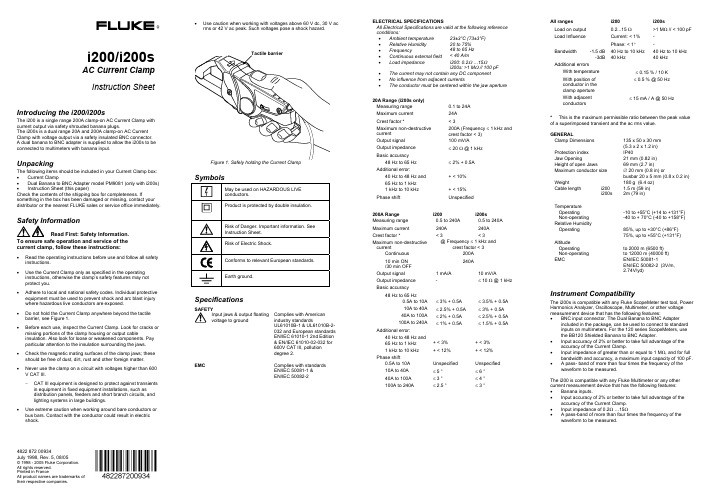
®i200/i200sAC Current ClampInstruction Sheet Introducing the i200/i200sThe i200 is a single range 200A clamp-on AC Current Clamp with current output via safety shrouded banana plugs.The i200s is a dual range 20A and 200A clamp-on AC Current Clamp with voltage output via a safety insulated BNC connector.A dual banana to BNC adapter is supplied to allow the i200s to be connected to multimeters with banana input.UnpackingThe following items should be included in your Current Clamp box: • CurrentClamp•Dual Banana to BNC Adapter model PM9081 (only with i200s) •Instruction Sheet (this paper)Check the contents of the shipping box for completeness. If something in the box has been damaged or missing, contact your distributor or the nearest FLUKE sales or service office immediately.Read First: Safety Information.To ensure safe operation and service of thecurrent clamp, follow these instructions:•Read the operating instructions before use and follow all safety instructions.•Use the Current Clamp only as specified in the operating instructions, otherwise the clamp’s safety features may notprotect you.•Adhere to local and national safety codes. Individual protective equipment must be used to prevent shock and arc blast injury where hazardous live conductors are exposed.•Do not hold the Current Clamp anywhere beyond the tactile barrier, see Figure 1.•Before each use, inspect the Current Clamp. Look for cracks or missing portions of the clamp housing or output cableinsulation. Also look for loose or weakened components. Payparticular attention to the insulation surrounding the jaws. •Check the magnetic mating surfaces of the clamp jaws; these should be free of dust, dirt, rust and other foreign matter. •Never use the clamp on a circuit with voltages higher than 600 V CAT III.−CAT III equipment is designed to protect against transients in equipment in fixed equipment installations, such asdistribution panels, feeders and short branch circuits, andlighting systems in large buildings.•Use extreme caution when working around bare conductors or bus bars. Contact with the conductor could result in electricshock. •Use caution when working with voltages above 60 V dc, 30 V acrms or 42 V ac peak. Such voltages pose a shock hazard.SpecificationsSAFETYInput jaws & output floatingvoltage to groundComplies with Americanindustry standardsUL61010B-1 & UL61010B-2-032 and European standardsEN/IEC 61010-1 2nd Edition& EN/IEC 61010-02-032 for600V CAT III, pollutiondegree 2.EMC Complies with standardsEN/IEC 50081-1 &EN/IEC 50082-2ELECTRICAL SPECIFICATIONSAll Electrical Specifications are valid at the following referenceconditions:•Ambient temperature 23±3°C (73±3°F)•Relative Humidity 20 to 75%•Frequency 48 to 65 Hz•Continuous external field < 40 A/m•Load impedance i200: 0.2Ω …15Ωi200s: >1 MΩ // 100 pF•The current may not contain any DC component•No influence from adjacent currents•The conductor must be centered within the jaw aperture20A Range (i200s only)Measuring range 0.1 to 24AMaximum current 24ACrest factor * < 3Maximum non-destructivecurrent200A (Frequency ≤ 1 kHz andcrest factor < 3)Output signal 100 mV/AOutput impedance ≤ 20 Ω @ 1 kHzBasic accuracy48 Hz to 65 Hz ≤ 2% + 0.5AAdditional error:40 Hz to 48 Hz and65 Hz to 1 kHz+ < 10%1 kHz to 10 kHz + < 15%Phase shift Unspecified200A Range i200 i200sMeasuring range 0.5 to 240A 0.5 to 240AMaximum current 240A 240ACrest factor * < 3 < 3Maximum non-destructivecurrent@ Frequency ≤ 1 kHz andcrest factor < 3Continuous 200A10 min ON/30 min OFF240AOutput signal 1 mA/A 10 mV/AOutput impedance - ≤ 10 Ω @ 1 kHzBasic accuracy48 Hz to 65 Hz0.5A to 10A ≤ 3% + 0.5A ≤ 3.5% + 0.5A10A to 40A ≤ 2.5% + 0.5A ≤ 3% + 0.5A40A to 100A ≤ 2% + 0.5A ≤ 2.5% + 0.5A100A to 240A ≤ 1% + 0.5A ≤ 1.5% + 0.5AAdditional error:40 Hz to 48 Hz and65 Hz to 1 kHz + < 3% + < 3%1 kHz to 10 kHz + < 12% + < 12%Phase shift0.5A to 10A Unspecified Unspecified10A to 40A ≤ 5 ° ≤ 6 °40A to 100A ≤ 3 ° ≤ 4 °100A to 240A ≤ 2.5 ° ≤ 3 °All ranges i200 i200sLoad on output 0.2...15 Ω >1MΩ // < 100 pFLoad Influence Current: < 1%Phase: < 1°--Bandwidth -1.5dB-3dB40 Hz to 10 kHz40 kHz40 Hz to 10 kHz40 kHzAdditional errorsWith temperature ≤ 0.15 % / 10 KWith position ofconductor in theclamp aperture≤ 0.5 % @ 50 HzWith adjacentconductors≤ 15 mA / A @ 50 Hz*This is the maximum permissible ratio between the peak valueof a superimposed transient and the ac rms value.GENERALClamp Dimensions 135 x 50 x 30 mm(5.3 x 2 x 1.2 in)Protection index IP40Jaw Opening 21 mm (0.82 in)Height of open Jaws 69 mm (2.7 in)Maximum conductor size ∅ 20 mm (0.8 in) orbusbar 20 x 5 mm (0.8 x 0.2 in)Weight 180 g (6.4 oz)Cable length i200i200s1.5 m (59 in)2m (79 in)TemperatureOperatingNon-operating-10 to +55°C (+14 to +131°F)-40 to + 70°C (-40 to +158°F)Relative HumidityOperating 85%, up to +30°C (+86°F)75%, up to +55°C (+131°F)AltitudeOperatingNon-operatingto 2000 m (6500 ft)to 12000 m (40000 ft)EMC EN/IEC50081-1EN/IEC 50082-2 (3V/m,2.74V/yd)Instrument CompatibilityThe i200s is compatible with any Fluke ScopeMeter test tool, PowerHarmonics Analyzer, Oscilloscope, Multimeter, or other voltagemeasurement device that has the following features:•BNC input connector. The Dual Banana to BNC Adapterincluded in the package, can be used to connect to standardinputs on multimeters. For the 120 series ScopeMeters, usethe BB120 Shielded Banana to BNC Adapter.•Input accuracy of 2% or better to take full advantage of theaccuracy of the Current Clamp.•Input impedance of greater than or equal to 1 MΩ, and for fullbandwidth and accuracy, a maximum input capacity of 100 pF.• A pass- band of more than four times the frequency of thewaveform to be measured.The i200 is compatible with any Fluke Multimeter or any othercurrent measurement device that has the following features:• Bananainputs.•Input accuracy of 2% or better to take full advantage of theaccuracy of the Current Clamp.•Input impedance of 0.2Ω …15Ω• A pass-band of more than four times the frequency of thewaveform to be measured.4822 872 00934July 1998, Rev. 5, 08/05© 1998 - 2005 Fluke Corporation. All rights reserved.Printed in FranceAll product names are trademarks of their respective companies.Using the Current ClampTo use the Current Clamp, follow these instructions:1. Connect the i200/i200s Current Clamp to the desired input onthe measuring instrument. i200: See Figure 2.i200s: See Figure 3. When you are using a multimeter, use the Dual Banana to BNC Adapter (PM9081) to connect the Current Clamp to the input.2. i200s: On the Current Clamp, select the least sensitive range(10 mV/A).3. i200s: Select the appropriate clamp sensitivity on yourScopeMeter test tool or oscilloscope.4. Position the Current Clamp perpendicular to and centeredaround the conductor.5. Make sure that the arrow marked on the clamp jaw pointstoward the load for phase measurements or away from the load (toward the source) for neutral measurements. (See Figure 4.)6. Observe the current value and waveform on the instrument’sdisplay.7. i200s: If desired, select a lower range on the Current Clampand set the corresponding sensitivity (mV/A setting) on the ScopeMeter test tool or oscilloscope.Example with multimeters for i200:Current Clamp sensitivity = 1 mA/A. Multimeter displays 168 mA.168AmA/A 1mA168Clamp Current y sensitivit value display current Actual ===Example with multimeters for i200s:Current Clamp set to 10 mV/A. Multimeter displays 1.85V.185AmV/A 10mV 1850mV/A 101.85VClamp Current y sensitivit value display current Actual ====Figure 2. Measurement Setup for i200Figure 3. Measurement Setup for i200sWarningIf the sensitivity setting (mV/A) of the ScopeMeter test tool or oscilloscope does not correspond with the setting of the Current Clamp, the ScopeMeter test tool or oscilloscope may display a much lower current than the actual value. This may result in a false and misleading reading and, as a consequence, incorrect measures to be taken.Figure 4. Orientation of the Current ClampMeasurement ConsiderationsObserve the following guidelines for positioning the Current Clamp Jaws: • Center the conductor inside the clamp jaws. • Make sure the clamp is perpendicular to the conductor. • Make sure that the arrow marked on the jaw of the CurrentClamp points toward the correct direction. Observe the following guidelines when making measurements: • Avoid taking measurements close to other current-carryingconductors. • On the i200s Current Clamp, select the most appropriate rangefor the current being measured to get the best accuracy.MaintenanceBefore each use, inspect the clamp. Look for cracks or missingportions of the clamp housing and output cable insulating cover and for loose or weakened components. Pay particular attention to the insulation surrounding the clamp jaws. Do not use a damaged clamp. If a clamp is damaged, tape it shut to prevent unintended operation. A damaged clamp under warranty will be promptly repaired or replaced (at Fluke's discretion) and returned at no charge.Cleaning and StoragePeriodically wipe the case with a damp cloth and detergent; do not use abrasives or solvents. Open the jaws and wipe the magnetic pole pieces with a lightly oiled cloth. Do not allow rust or corrosion to form on the magnetic core ends.If your Current Clamp does not workIf the Current Clamp does not perform properly, use the following steps to help isolate the problem: • Inspect the jaw mating surface for cleanliness. If any foreignmaterial is present, the jaws will not close properly and errors will result. • Verify that the function selection and range on the Multimeter,ScopeMeter test tool or oscilloscope are correct and adjusted to the sensitivity of the Current Clamp.LIMITED WARRANTY & LIMITATION OF LIABILITYThis Fluke product will be free from defects in material andworkmanship for one year from the date of purchase. This warranty does not cover fuses, disposable batteries or damage fromaccident, neglect, misuse or abnormal conditions of operation or handling. Resellers are not authorized to extend any other warranty on Fluke’s behalf. To obtain service during the warranty period,send your defective product to the nearest Fluke Authorized Service Center with a description of the problem.THIS WARRANTY IS YOUR ONLY REMEDY. NO OTHER WARRANTIES, SUCH AS FITNESS FOR A PARTICULAR PURPOSE, ARE EXPRESSED OR IMPLIED. FLUKE IS NOT LIABLE FOR ANY SPECIAL, INDIRECT, INCIDENTAL ORCONSEQUENTIAL DAMAGES OR LOSSES, ARISING FROM ANY CAUSE OR THEORY.Since some states or countries do not allow the exclusion or limitation of an implied warranty or of incidental or consequential damages, this limitation of liability may not apply to you. Fluke Corporation Fluke Industrial B.V. P.O. Box 9090 P.O. Box 90 Everett WA7600 AB Almelo 98206-9090, USAThe NetherlandsSERVICE CENTERSTo locate an authorized service center,visit us on the World Wide Web:or call Fluke using any of the phone numbers listed below:+1-888-993-5853 in U.S.A. and Canada+31-40-267-5200 in Europe +1-425-446-5500 from other countriesMeasurement ata neutral conductor Measurement ata phase conductor。
Fluke OS200系列无人机热电偶温度计说明书

J-33The OS201 is an instrument and fixed probe with a semi-flexibleshaft, making these models suitable for one-handed operation. The OS202 consists of an instrument and a remote probe with a semi-flexible shaft that is connected to the instrument by a retractable coiled cord, making it suitable for two-handed operation. The semi-flexible shaft on the OS201and OS202 makes these models ideal for measuring the temperature of inaccessible or awkwardly placed objects.The OS201 and OS202 are more suitable for measuring thetemperature of more distant objects.SpecificationsAccuracy: ±1% rdg ±1°C(±1%rdg ±2°F) for OS201, OS202Repeatability:±0.5°C ±1 digit (±1°F ±1 digit) given a constant distance from the target and stable ambient temperatureResolution: 1°C/1°FSample Rate:2.5 times per second Response Time:< 1 sec (63% of peak)Measuring Mode:ContinuousOS200 Series Starts at$267OS201C $267OS202C $345OS200-COVER Rubber Boot$34Low-Cost Handheld Infrared Pyrometers 1° ResolutionAmbient Operating Range:-10 to 50°C (14 to 122°F)Power: 9 V alkaline battery, included (MN1604 or equivalent)Battery Life: 500 hr typical (alkaline battery)Display:31⁄2digit backlit LCD Spectral Response:6 to 14 micronsDimensions (Instrument Only,Excluding Probe): 140 H x 70 W x26 mm D (5.6 x 2.8 x 1.04")ߜ-20 to 250°C(-5 to 482°F) Range ߜ±1% Reading ±1°C (±1% Reading 2°F)AccuracyߜBacklit LCD Display with 1° Resolution ߜFixed Emissivity ModelsApplications •Quality Control•Plant and EquipmentServicing •PreventiveMaintenance and Troubleshooting•Energy Management,Electrical, HVACDISCONTINUEDDISCONTINUEDDISCONTINUEDDISCONTINUEDJ-34Ordering Example: OS201C infrared pyrometer with -20 to 250°C range and fixed 0.95 emissivity ($267) plus OS200-COVER protective rubber boot ($34), $267 + 34 = $301.Field of View, OS201 and OS202CANADA www.omega.ca Laval(Quebec) 1-800-TC-OMEGA UNITED KINGDOM www. Manchester, England0800-488-488GERMANY www.omega.deDeckenpfronn, Germany************FRANCE www.omega.frGuyancourt, France088-466-342BENELUX www.omega.nl Amstelveen, NL 0800-099-33-44UNITED STATES 1-800-TC-OMEGA Stamford, CT.CZECH REPUBLIC www.omegaeng.cz Karviná, Czech Republic596-311-899TemperatureCalibrators, Connectors, General Test and MeasurementInstruments, Glass Bulb Thermometers, Handheld Instruments for Temperature Measurement, Ice Point References,Indicating Labels, Crayons, Cements and Lacquers, Infrared Temperature Measurement Instruments, Recorders Relative Humidity Measurement Instruments, RTD Probes, Elements and Assemblies, Temperature & Process Meters, Timers and Counters, Temperature and Process Controllers and Power Switching Devices, Thermistor Elements, Probes andAssemblies,Thermocouples Thermowells and Head and Well Assemblies, Transmitters, WirePressure, Strain and ForceDisplacement Transducers, Dynamic Measurement Force Sensors, Instrumentation for Pressure and Strain Measurements, Load Cells, Pressure Gauges, PressureReference Section, Pressure Switches, Pressure Transducers, Proximity Transducers, Regulators,Strain Gages, Torque Transducers, ValvespH and ConductivityConductivity Instrumentation, Dissolved OxygenInstrumentation, Environmental Instrumentation, pH Electrodes and Instruments, Water and Soil Analysis InstrumentationHeatersBand Heaters, Cartridge Heaters, Circulation Heaters, Comfort Heaters, Controllers, Meters and SwitchingDevices, Flexible Heaters, General Test and Measurement Instruments, Heater Hook-up Wire, Heating Cable Systems, Immersion Heaters, Process Air and Duct, Heaters, Radiant Heaters, Strip Heaters, Tubular HeatersFlow and LevelAir Velocity Indicators, Doppler Flowmeters, LevelMeasurement, Magnetic Flowmeters, Mass Flowmeters,Pitot Tubes, Pumps, Rotameters, Turbine and Paddle Wheel Flowmeters, Ultrasonic Flowmeters, Valves, Variable Area Flowmeters, Vortex Shedding FlowmetersData AcquisitionAuto-Dialers and Alarm Monitoring Systems, Communication Products and Converters, Data Acquisition and Analysis Software, Data LoggersPlug-in Cards, Signal Conditioners, USB, RS232, RS485 and Parallel Port Data Acquisition Systems, Wireless Transmitters and Receivers。
福禄克FLUKE过程校准仪使用说明书
福禄克FLUKE过程校准仪中文说明书一,测量和信号输出功能一览表二、初识校准仪1.当你第一次取出校准仪,你需要将电池充电见图9,给电池充电2小时。
2.将电池放入校准仪中。
3.连接校准仪的电压输出端和输入端如下:连接最左端的一对插孔(V、Ω、RTD输出)和最右端的一对插孔(VMEAS)(见图3)。
图3 跨接线连接图4 输入输出的例子4.开机按⊙,按▲,▼以调整对比度。
以达到最好的显示效果。
校准仪在接通电源时是直流电压的测量功能,可以在一对VMEAS输入插孔中得到读数。
5.按SETUP键,进入输出屏幕显示,校准仪将仍测量直流电压,并且你可以在显示屏顶部看到其测量情况。
6.按V—…键,选择直流电压输出。
按数字键5和ENTER=开始输出5.0000V直流电压。
7.按MEAS SOURCE键,进入双重显示屏幕。
测量、输出同时工作。
校准仪同时输出和测量直流电压。
你将在上半部屏幕看到测量读数,在下半部屏幕看到输出值,如图4所示。
三、操作功能1.输入和输出插孔图5所示,校准器输入和输出插孔,表2解释它的用途。
表2 输入/输出插孔和连接器序号性能说明1 外接电源插孔BE9005电源阻隔器插孔,可在交流电供工作室内使用。
本输入不能给电池充电。
2 !串行接口连接校准仪与个人计算机。
3 压力模块连接器连接校准仪与压力模块4 TC输入/输出测量或模拟输出热电偶插孔。
本插孔接受微型扁平(中心距离7.9mm或0.312英寸)的电偶插头5,6 !MEAS V插孔测量电压、频率、或三线或四线RTDS(热电阻温度计)输入插孔7,8 !SOURCE(输出)mA测量mAΩRTD插孔输出或测量电流、电阻和RTDS插孔,并提供回路电源9,10 !SOURE(输出)V Ω RTD插孔输出电压、电阻、频率、和模拟RTDS输出插孔图5 输入/输出插孔和连接2.按键校准仪按键如图6所示,表3解释它们的功能,有4个未带标记的兰色按键,在显示屏幕下面称之为功能键。
iTC200操作指南

引言概述:本文是iTC200操作指南的第二部分。
iTC200是一款先进的测试仪器,主要用于行业中的数据采集和信号处理。
本文将重点介绍iTC200的操作方法和技巧,以帮助用户更好地使用该设备。
正文内容:一、iTC200的基本操作1.iTC200的开机和关机方法插上电源适配器,并将其连接到设备。
按下电源按钮,设备将开始启动,显示屏将显示iTC200的标识。
关机时,长按电源按钮,直到设备完全关闭。
2.操作界面的简介设备的主界面由显示屏,按键和旋钮组成。
显示屏显示当前的测量结果和操作菜单。
按键用于导航和确认操作,旋钮用于调整参数和输入数值。
3.基本测量功能的使用iTC200支持多种常见的测量功能,如电流测量、电压测量、电阻测量等。
在主界面上选择需要测量的项目,并按照设备的提示进行操作。
二、iTC200的高级功能1.数据采集功能的使用iTC200可以进行数据采集和存储,以便后续的数据分析和处理。
在主界面上选择数据采集功能,并设置采样率、采样时间等参数。
开始采集后,iTC200将自动记录数据,并可以通过USB或网络进行导出。
2.信号处理功能的应用iTC200具有强大的信号处理能力,可以进行滤波、频谱分析、FFT变换等操作。
在主界面上选择信号处理功能,并设置滤波器类型、频率范围等参数。
对于采集到的信号数据,iTC200可以实时展示处理结果,并支持保存和导出。
3.外部控制接口的使用iTC200支持外部控制接口,可以通过RS232或GPIB等接口与其他设备进行通信。
在主界面上选择外部控制功能,并设置接口类型和通信参数。
iTC200将根据设定的接口规范与外部设备进行通信,并实现数据的交互和控制。
4.软件的远程控制iTC200可以通过软件进行远程控制和管理,提供更便捷的操作和分析工具。
在计算机上安装iTC200的远程控制软件,并通过网络连接到iTC200。
利用软件提供的界面和功能,用户可以实时监控和操作iTC200,以及进行数据管理和分析。
