STC1120-704K中文资料
704手册

1快速安装指南本部分列出对Horizon 仪表进行快速安装,接线和设定的关键步骤。
供有经验的电气安装人员参考。
注意 7XD 7XR 或7XT型探头仅用于安全切断/溢出工况。
所有其他型号的导波雷达的安装,都应该保证被测介质的最高液面应低于雷达天线过程连接150毫米。
此情况包括使用立管等人为抬高探头高度的工况。
1.1A必备工具.扳手 (同轴探头38毫米,双杆探头47毫米,传感器部分 38毫米).一字螺丝刀.斜口钳 2.5毫米内六角扳手.万用表.24 V 电源B设定必备信息开始设定前,请确认以下必备信息Units 测量中使用的工程单位( 英寸或厘米)?Probe module 仪表型号信息中列出的型号是什么?(探头型号的头4位内容Probe length 探头长度Offset 从探头底端到0%参考点的距离Dielectric 被测介质的介电常数Set 4 m A 对应4毫安输出时的0%参考点位置Set20 m A 对应20毫安输出时的100%参考点位置(7XB双杆探头从顶部起100毫米范围为信号死区;7XF,7X1单杆探头从顶部起178毫米为信号死区)1.2开始安装安装时注意. 保护探头顶部连接的塑料帽在最后安装传感器之前不要取走. 在传感器的过程连接上不要使用任何的密封黏合剂或TFE胶带,该连接处是使用 Viton 环密封.. 注意保护探头顶部的高频连接干燥清洁,必要时可用酒精擦拭,用棉签擦干.. 传感器和探头部分的连接,随手上紧后,再用扳手上紧1/4到1/2圈.1.3接线打开仪表的外壳用手用力夹住液晶显示键盘往上拔出接线位置如下图所示1.3.4 注意连接电源的正负极性;1.3.5 注意在电源和仪表两端分别接地.快速设定A仪表键使用方法.仪表上电后,显示将每5秒钟交替显示液位,%输出,和回路电流..使用↑和↓键来在设定菜单中移动..当按下输入键时,显示中第一行的走后一个字母将变为感叹号,此时可用↑和↓键来改变参数的大小,再用输入键来确定即可.注意,每次改变参数后,如果需要断电,须给仪表10秒钟的时间来刷新内部设置.如左图①Units 测量中使用的工程单位( 英寸或厘米)?② Probemodule 仪表型号信息中列出的型号是什么?(探头型号的头4位内容)③ Probe mount 探头的安装形式(NPT ,BSP还是法兰?)④ Probe length 探杆的长度⑤Offset 从探头底端到0%参考点的距离⑥Dielectric 被测介质的介电常数⑦Set 4 m A 对应4毫安输出时的0%参考点位置⑧Set20 m A 对应20毫安输出时的100%参考点位置完全安装.本部分内容为安装的详细内容。
新亚洲na704l电流表说明

新亚洲na704l电流表说明新亚洲NA704L电流表是一种用于测量电流的仪器。
它具有精确度高、可靠性强、操作简便等特点,广泛应用于工业生产、科研实验和电力系统等领域。
下面将对NA704L电流表进行全面详细的说明。
一、产品概述NA704L电流表是一种数字式电流表,采用先进的微处理器技术和高精度的测量芯片,能够准确测量直流和交流电流,并以数字形式显示结果。
该仪器具有多种功能和特点,适用于不同场合的电流测量需求。
二、外观和结构1. 外观:NA704L电流表外观简洁大方,采用黑色塑料壳体,具有良好的抗震性能和耐磨损性。
仪表面板上设有LCD液晶屏幕和按键,便于用户进行操作和读数。
2. 结构:NA704L电流表采用单相结构设计,内部包含测量芯片、显示模块、控制模块等核心部件。
该仪器还配备了保护装置,如过载保护、短路保护等,以确保使用安全。
三、技术参数1. 电流测量范围:0-20A、0-200A、0-1000A等多个档位可选。
2. 测量精度:±(0.5%+2d)。
3. 显示方式:数字显示,最大显示位数为4位。
4. 供电方式:交流220V或直流24V。
5. 工作温度范围:-10℃至50℃。
6. 外形尺寸:120mm×80mm×50mm。
四、功能特点1. 高精度测量:NA704L电流表采用高精度的测量芯片,能够实现对电流的准确测量,并且具有较小的误差范围,保证了测量结果的可靠性。
2. 宽泛应用范围:NA704L电流表适用于直流和交流电流的测量,可以满足不同领域对电流测量的需求,如工业生产中的设备监控、科研实验中的电路测试等。
3. 数字显示:该仪器采用液晶屏幕进行数据显示,数字清晰可见,便于用户读取结果,并且可以在不同光照条件下正常工作。
4. 自动切换档位:NA704L电流表具有自动切换档位功能,能够根据被测电流的大小自动选择合适的测量范围,提高了使用的便利性。
5. 数据保持功能:该仪器配备了数据保持功能,能够将当前测量结果锁定在屏幕上,方便用户记录和查看。
PLC在伺服角钢冲孔机上的应用课件
FATEK 值徥您信賴的品牌
Page:5
➢产品配置示意图
产品配置
FATEK 值徥您信賴的品牌
【伺服角钢冲孔机产品配置示意图】
Page:6
产品配置
➢产品配置清单说明
控制 单元 操作单元 驱动单元
执行单元
检测单元
产品类型 永宏PLC
永宏HMI 永宏伺服
气缸 油缸 传感器ቤተ መጻሕፍቲ ባይዱ
硬件明细表
产品型号 FBs-40MAT2-AC
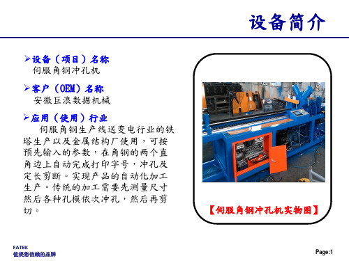
设备简介
【伺服角钢冲孔机实物图】
FATEK 值徥您信賴的品牌
Page:1
设备组成
➢设备组成说明 伺服角钢冲孔机的机械(设备)结构主要由五个模块功能组成,分
别是送料部分、孔模1部分、孔模2部分、剪切部分和尾料夹持部分。
FATEK 值徥您信賴的品牌
Page:2
➢设备组成之料仓模块组成示意图
设备组成
【送料部分组件组件】
FATEK 值徥您信賴的品牌
Page:9
技术特点&难点2
➢参数设置程序 在进行伺服角钢冲孔机的PLC整体
程序设计和规划时,参数设置程序采 用的是永宏PLC【FUN 141(伺服参数 设置)】指令来对送料伺服相关参数 进行设置;采用永宏PLC的参数设置指 令既可以完成参数设置程序的编辑, 为程序编辑和调试者提供了极大的方 便。
户的要求要有11个不同规格的产品,长度,1#孔模和2#孔模都是独立的, 不同规格的产品要在一个自动流程中连续完成。因此,将长度,1#孔模 和2#孔模都单独的作为一个比较对象,先得出各个对象相对于当前送料 长度最近的值作为送料定位的目标,送料完成进行冲剪,之后再刷新长 度和孔模的
FATEK 值徥您信賴的品牌
SR701 SR704 AC Current Probes用户手册说明书
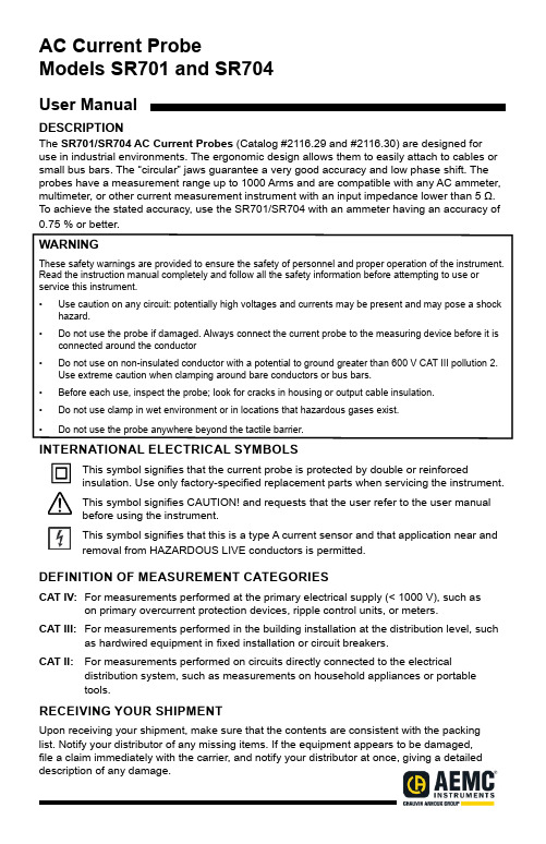
AC Current ProbeModels SR701 and SR704User ManualDESCRIPTIONThe SR701/SR704 AC Current Probes (Catalog #2116.29 and #2116.30) are designed for use in industrial environments. The ergonomic design allows them to easily attach to cables or small bus bars. The “circular” jaws guarantee a very good accuracy and low phase shift. The probes have a measurement range up to 1000 Arms and are compatible with any AC ammeter, multimeter, or other current measurement instrument with an input impedance lower than 5 Ω. To achieve the stated accuracy, use the SR701/SR704 with an ammeter having an accuracy of 0.75 % or better.WARNINGThese safety warnings are provided to ensure the safety of personnel and proper operation of the instrument. Read the instruction manual completely and follow all the safety information before attempting to use or service this instrument.• Use caution on any circuit: potentially high voltages and currents may be present and may pose a shock hazard.• Do not use the probe if damaged. Always connect the current probe to the measuring device before it is connected around the conductor• Do not use on non-insulated conductor with a potential to ground greater than 600 V CAT III pollution 2.Use extreme caution when clamping around bare conductors or bus bars.• Before each use, inspect the probe; look for cracks in housing or output cable insulation.• Do not use clamp in wet environment or in locations that hazardous gases exist.• Do not use the probe anywhere beyond the tactile barrier.INTERNATIONAL ELECTRICAL SYMBOLSThis symbol signifies that the current probe is protected by double or reinforcedinsulation. Use only factory-specified replacement parts when servicing the instrument.This symbol signifies CAUTION! and requests that the user refer to the user manualbefore using the instrument.This symbol signifies that this is a type A current sensor and that application near andremoval from HAZARDOUS LIVE conductors is permitted.DEFINITION OF MEASUREMENT CATEGORIESCAT IV: For measurements performed at the primary electrical supply (< 1000 V), such as on primary overcurrent protection devices, ripple control units, or meters.CAT III:For measurements performed in the building installation at the distribution level, such as hardwired equipment in fixed installation or circuit breakers.CAT II: For measurements performed on circuits directly connected to the electrical distribution system, such as measurements on household appliances or portabletools.RECEIVING YOUR SHIPMENTUpon receiving your shipment, make sure that the contents are consistent with the packing list. Notify your distributor of any missing items. If the equipment appears to be damaged,file a claim immediately with the carrier, and notify your distributor at once, giving a detailed description of any damage.CURRENT PROBE - SR701/SR704 DRAWINGELECTRICAL SPECIFICATIONS Current Range: 1 mA to 1200 A ac Transformation Ratio: 1000:1 Output Signal: 1 mA AC/A ac(1 A ac at 1000 A)Accuracy and Phase Shift*: Accuracy:(1 to 100) mA: ±3 % Reading ±5 mA(0.1 to 1) A: ±2 % Reading ±3 mA(1 to 10) A: ±1 % Reading(10 to 100) A: ±0.5 % Reading (100 to 1200) A: ±0.3 % Reading Phase Shift:(1 to 100) mA: Not Specified(0.1 to 1) A: Not Specified(1 to 10) A: ≤ 2 °(10 to 100) A: ≤ 1 °(100 to 1200): ≤ 0.7 °*Referenced conditions: 23 °C ± 3° K, (20 to 75) % RH, (48 to 65) Hz, external magnetic field < 40 A/m, no DC component, no external current carrying conductor, test sample cen-tered. Load Impedence: ≤ 1 ΩOverload: 1200 A for 40 min on, 20 min off Accuracy: Per IEC 185Frequency Range: 30 Hz to 5 kHz; current derating above 1 kHz using the formula: 1000 A × 1F (kHz)Load Impedence: 5 Ω maxWorking Voltage: 600 V CAT IIICommon Mode Voltage: 600 V CAT III Open Secondary Voltage:< 25 V by limiting circuitInfluence of Adjacent Conductor:< 1 mA/AACWeight:1.21 lbs (550 g)Output:SR701: (2) standard safety banana jacks (4 mm)SR704: 5 ft (1.5 m) lead with safety 4 mm banana plugSAFETY SPECIFICATIONSElectrical:Double insulation or reinforced insulation be-tween the primary or secondary and the outer case of the handle conforms to IEC 1010-2-032.Common Mode Voltage:600 V CAT III, Pollution Degree 2Electromagnetic Compatibility:Emission and immunity in an industrial envi -ronment according to EN61326-1ORDERING INFORMATIONAC Current Probe SR701 ........Cat #2116.29 AC Current Probe SR704 ........Cat #2116.30Accessories:Lead, set of 2, 5 ft Safety Leads(1000 V CAT IV) .........................Cat #2152.24 Adapter BNC (Male) - Banana (Female)(XM-BB) (600 V CAT III) .............Cat #2118.46 Banana plug adapter(to non-recessed plug)................Cat #1017.45Influence of Conductor in Jaw Opening: 0.1 % of ReadingInfluence of Frequency:From (30 to 48) Hz: < 0.5 % of R From (65 to 1000) Hz: < 1 % of R From (1 to 5) kHz: < 2 % of R MECHANICAL SPECIFICATIONS Operating Temperature:(14 to 122) °F (-10 to 50) °C)Storage Temperature:(-4 to 158) °F (-20 to 70) °C Influence of Temperature:< 0.15 % per 10 °KInfluence of Humidity:From (10 to 90) % RH: 0.1 %Jaw Opening:2.25 in (57mm) max Maximum Conductor Size:2.05 in (52 mm)Envelope Protection: IP 40 (IEC 529)Drop Test: 1 m (IEC 68-2-32)Mechanical Shock: 100 g (IEC 68-2-27)Vibration:(5 to 15) Hz, 0.15 mm (IEC 68-2-6)(15 to 25) Hz, 1 mm (25 to 55) Hz, 0.25 mmMaterial:Handles and jaws: Polycarbonate UL94V0Dimensions:(4.37 x 8.50 x 1.77) in (111 x 216 x 45) mmOPERATIONPlease make sure that you have already read and fully understand the WARNING section on page 1.Making Measurements with the AC Current Probe Models SR701/SR740•Connect the black lead of the current probe to “common” and the red lead to the ACcurrent input on your DMM or other current measuring instrument. Select the appropriate current range (2 A AC range). Clamp the probe around the conductor to be tested with the arrow pointed toward the load. If the reading is less than 200 mA, select the lower range until you obtain the best resolution. Read the value display on the DMM and multiply it by the probe ratio (1000/1). (If reading = 0.659 A, the current flowing through the probe is 0.659 A x 1000 = 659 A AC ).•For best accuracy, avoid if possible, the proximity of other conductors which may createnoise.Tips For Making Precise Measurements• When using a current probe with a meter, please select the range that provides the best resolution. Failure to do this may result in measurement errors.• Make sure that probe jaw mating surfaces are free of dust and contamination.Contaminants cause air gaps between the jaws, increasing the phase shift betweenprimary and secondary. It is very critical for power measurement.MAINTENANCEWarning• For maintenance use only original replacement parts.• To avoid electrical shock, do not attempt to perform any service on the device unless you are qualified to do so.• To avoid electrical shock and/or damage to the instrument, do not allow water or other foreign agents to come into contact with the probe.CleaningTo ensure optimum performance, it is important to keep the probe jaw mating surfaces clean at all times. Failure to do so may result in error in readings. To clean the probe jaws, use very fine sand paper (fine 600) to avoid scratching the jaw, and then gently clean with a soft, oiled cloth. REPAIR AND CALIBRATIONYou must contact our Service Center for a Customer Service Authorization number (CSA#). This will ensure that, when your instrument arrives, it will be tracked and processed promptly. Please write the CSA# on the outside of the shipping container.Ship To: Chauvin Arnoux®, Inc. d.b.a. AEMC® Instruments15 Faraday Drive • Dover, NH 03820 USAPhone: (800) 945-2362 (Ext. 360) • (603) 749-6434 (Ext. 360)Fax: (603) 742-2346 • E-mail: ***************(Or contact your authorized distributor)NOTE: You must obtain a CSA# before returning any instrument. TECHNICAL AND SALES ASSISTANCEIf you are experiencing any technical problems, or require any assistance with the proper operation or application of your instrument, please call, e-mail or fax our technical support team: Contact: Chauvin Arnoux®, Inc. d.b.a. AEMC® InstrumentsPhone: (800) 945-2362 (Ext. 351) or (603) 749-6434 (Ext. 351)Fax: (603) 742-2346 • E-mail: ********************LIMITED WARRANTYThe current probe is warrantied to the owner for a period of two years from the date of original purchase against defects in manufacture. This limited warranty is given by AEMC®Instruments, not by the distributor from whom it was purchased. This warranty is void if the unit has been tampered with, abused, or if the defect is related to service not performed by AEMC® Instruments.Full warranty coverage and product registration is available on our website at:/warranty.html.Please print the online Warranty Coverage Information for your records.99-MAN 100166.v19 03/23。
Helios 11 240 伏特斯坦 4灯控制器说明书
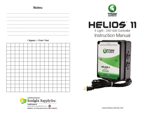
WARRANTY SERVICE: Please read warranty information first If after reviewing the troubleshooting tips the unit will still not work, you should return it to the Dealer where you purchased the controller. They will be able to further evaluate the unit and test its various components and quite possibly will be able to identify and/or fix any problems. If the Dealer is unable to fix the unit, they will return it to us for factory repair. If there are no Dealers in your area, you may contact us directly for technical support. If we cannot help you resolve the problem over the phone, we will issue you an RMA # (return merchandise authorization) authorizing you to return the unit to us for factory reconditioning (if the unit is under warranty). Contact the number below for an RMA # and shipping address. Complete the form below and include it with your unit. Also please write the RMA # on the outside of the box. Please package the unit in its original packaging. If it is damaged in shipment we cannot be responsible. Once we receive the unit back, we will repair or replace the controller within 48 hours (business) and return it to you freight prepaid via UPS ground shipment.
DSE705 ATS控制模块操作手册说明书

COMPLEX SOLUTIONSMADE SIMPLEDEEP SEA ELECTRONICS PLCDSE705ATS CONTROL MODULEOPERATING MANUALDeep Sea Electronics PlcHighfield HouseHunmanbyNorth YorkshireYO14 0PHENGLANDSales Tel: +44 (0) 1723 890099Sales Fax: +44 (0) 1723 893303E-mail: ********************Website: DSE Model 704 Control System Operators Manual© Deep Sea Electronics PlcAll rights reserved. No part of this publication may be reproduced in any material form (including photocopying or storing in any medium by electronic means or other) without the written permission of the copyright holder except in accordance with the provisions of the Copyright, Designs and Patents Act 1988.Applications for the copyright holder’s written permission to reproduce any part of this publication should be addressed to Deep Sea Electronics Plc at the address above.Any reference to trademarked product names used within this publication is owned by their respective companies.Deep Sea Electronics Plc reserves the right to change the contents of this document without priornotice.- 2 - 057-043 705 Operating Instructions Issue 1.1 18/06/2007 JRTABLE OF CONTENTS1 INTRODUCTION (4)2 DESCRIPTION OF OPERATION (4)2.1 M ANUAL RUN ON LOAD (4)2.2 M ANUAL RUN OFF LOAD (4)2.3 A UTOMATIC MODE OF OPERATION (5)3 CONFIGURATION INSTRUCTIONS (6)4 CONFIGURATION TABLES (7)5 TERMINAL DESCRIPTION (9)6 SPECIFICATION (10)7 SOLID STATE OUTPUTS (11)7.1 T YPICAL CONNECTIONS (11)8 DIMENSIONS (12)9 TYPICAL CONNECTIONS (12)057-043 705 Operating Instructions Issue 1.1 18/06/2007 JR - 3 -1 INTRODUCTIONThe 705 is a configurable A utomatic T ransfer S witch control module, and is designed to work in conjunction with generator control modules that will accept a remote start input. It monitors the incoming AC mains supply (1 or 3 phases) for under voltage. If the voltage falls out of limits the module will issue a start command to the generating set controller. Once the set is available and producing an output within limits the ATS module will control the transfer devices and switch the load from the mains to the generating set. Should the mains supply return to within limits the module will command a return to the mains supply and shut down the generator after a suitable cooling run. Various timing sequences are used to prevent nuisance starting and supply breaks. Configuration is via the front panel. No other equipment such as a computer or programming lead is required.2 DESCRIPTION OF OPERATION2.1 MANUAL RUN ON LOADTo initiate a start sequence in Manual Run On Loadsequence is initiated.The start/run output is activated.Once the unit detects the alternator frequency of 45Hz, the Warm Up timer is initiated, allowing theengine to stabilise before accepting the load.The load will be transferred to the generator.The module will continue to run in this mode until another mode is selected.If the generator should fail and the mains (utility) are available, the load is transferred back to themains (utility).2.2 MANUAL RUN OFF LOADTo initiate a start sequence in Manual Run Off Loadsequence is initiated.The start/run output is activated.The generator will be run off load and no further action is taken.If during this time the mains (utility) should fail, the load will be transferred to the generator.However, the unit will NOT return the load to the mains (utility). The load will stay with thegenerator until another mode is selected.- 4 - 057-043 705 Operating Instructions Issue 1.1 18/06/2007 JR057-043 705 Operating Instructions Issue 1.1 18/06/2007 JR - 5 -2.3confirms this action.Whether the start sequence is initiated by mains (utility) failure, or by remote start input, the following sequence id followed:To allow for short term mains supply transient conditions or false remote start signals, the Mains Fail Delay timer is initiated. After this delay the start/Run output is activated.Once the unit detects the alternator frequency of 45Hz, the Warm Up timer is initiated, allowing the engine to stabilise before accepting the load.If the remote start is being used and has been configured to Remote start is on load, or the mains has failed, the load will be transferred to the generator.On the return of the mains supply, (or removal of the Remote Start signal if the set was started by remote signal), the Mains Return delay timer is initiated. Once it has timed out, the load is transferred back to the mains (utility). The Cooling timer is then initiated, allowing the engine a cooling down period off load before shutting down. Once the Coolingtimer expires the Start/Run output is de-activated.If the mains should fail (or a Remote Start signal is re-activated) whilst the generator is Cooling down, the load will be immediately transferred to the generator.If the generator should fail, i.e. frequency falls below 20Hz the unit will switch back to the mains, even if the mains is not available.- 6 - 057-043 705 Operating Instructions Issue 1.1 18/06/2007 JR3 CONFIGURATION INSTRUCTIONS♦ With the unit in AutoConfiguration Mode is selected by operation of a smallswitch on the rear, left-hand edge of the PCB. This is partially hidden to prevent accidental operation.♦ Once Configuration Mode is selected, the ‘Auto’ LED will commence rapid flashing, and allnormal operation is suspended.♦ The Run On Load the required function. The 5 left-hand LED’s will form the code. See configuration table over leaf.♦ The Run Off Load right-hand LED’s inform the user of the current setting for the chosen function. See configuration table over leaf.♦ When the required parameters are displayed, pressing the Auto the new setting, and the process is repeated for each function change.♦ When configuration is complete, the Configuration Mode Selector Switch should be returnedto the ‘Normal’ position.Parameter Value4 CONFIGURATION TABLESFunction {{{{{{{{Value (Default in Bold) Start Delay {{{O{{{{0 Seconds{{O 5 Seconds{O{10 Seconds{O O15 SecondsO{{20 SecondsO{O30 SecondsO O{60 SecondsO O O180 Seconds Used to give a delay between mains failure and starting the engine. Used to prevent the generating from starting on brown outs (dips) or short mains outages.Mains Return Delay {{{O O{{{0 Seconds{{O 5 Seconds{O{10 Seconds{O O15 SecondsO{{20 SecondsO{O30 SecondsO O{60 SecondsO O O180 Seconds Used to give a delay between the mains returning and the system switching the load back to the mains. Used to ensure that the mains is steady before this action is executed.Warm Up Timer {{O{O{{{0 Seconds{{O 5 Seconds{O{10 Seconds{O O15 SecondsO{{20 SecondsO{O30 SecondsO O{60 SecondsO O O180 Seconds Delay between the engine being available for use, and the closure of the generator load-switching device to allow time for the engine to warm before being loaded.Cooling Timer {{O O{{{{0 Seconds{{O 5 Seconds{O{10 Seconds{O O15 SecondsO{{20 SecondsO{O30 SecondsO O{60 SecondsO O O180 Seconds Delay between opening the generator load-switching device and stopping the engine to allow time for the engine to cool down before being stopped. This is particularly useful when used in conjunction with turbo-charged engines.Remote Start Input Type {O O O{{{{Remote Start{{O Simulate MainsProgrammable input can be configured to one of the following.♦Remote start – If the input is active the generator will be started, and stopped if the input is deactive. Mains fail is allways active.♦Simulated mains – If the input is active the generator will not start in the event of a mains failure. E.G. if the generator is supporting a non 24 hour operation, a 24 hour timer can be used to prevent a mains failure fromstarting the generator and taking load.057-043 705 Operating Instructions Issue 1.1 18/06/2007 JR - 7 -Function {{{{{{{{Value (Default in Bold)Remote Start Function {O O O O{{{Remote Start Is Off load{{O Remote Start Is OnLoadThe remote start input can be configured to one of the following.♦Remote start is off load – The generator will start and run off load when the remote start input is active.♦Remote start is on load – The generator will start, and the load transferred to the generator when the remote start is active.Auxiliary Output 1 Function O{{O{{{{Not used{{O Mains Failure{O{Generator Available{O O Generator On LoadO{{Mains On LoadO{O System in AutoO O{Close to neutral PositionProgrammable output can be configured to one of the following.♦Mains Failure. - The output is energised after the delay mains fail timer has elapsed and stays energised until the delay mains return timer has elapsed.♦Generator Available. - The output is energised after the warm up timer has elapsed and generator voltage is sensed.♦Generator On Load. - The output is energised when the unit has switched over to generator supply.♦Mains On Load. - The output is energised when the unit has switched over to mains supply.♦System in auto. - The output is energised when the unit is in automatic mode.♦Close to Neutral Position. - The output is energised when the close to neutral position input is active.Auxiliary Output 2 Function O{{O O{{{Not used{{O Mains Failure{O{Generator Available{O O Generator On LoadO{{Mains On LoadO{O System in AutoO O{Close to neutral PositionProgrammable output can be configured to one of the following.♦Mains Failure. - The output is energised after the delay mains fail timer has elapsed and stays energised until the delay mains return timer has elapsed.♦Generator Available. - The output is energised after the warm up timer has elapsed and generator voltage is sensed.♦Generator On Load. - The output is energised when the unit has switched over to generator supply.♦Mains On Load. - The output is energised when the unit has switched over to mains supply.♦System in auto. - The output is energised when the unit is in automatic mode.♦Close to Neutral Position. - The output is energised when the close to neutral position input is active.Mains Under Voltage (Trip / Return) O{O{{{{{60V / 70V{{O70V / 80V{O{80V / 90V{O O90V / 100VO{{120V / 140VO{O140V / 160VO O{160V / 180VO O O180V /200VIf for example 180V/200V is selected the generator will be started and the load transferred if any phase falls below 180V with respect to the neutral for the duration of the delay start timer. The load will be transferred back to mains when the mains voltage returns to 200V or higher for the duration of the mains return timer. (The system must be in Auto)- 8 - 057-043 705 Operating Instructions Issue 1.1 18/06/2007 JR057-043 705 Operating Instructions Issue 1.1 18/06/2007 JR - 9 -5 TERMINAL DESCRIPTION1 DC Plant Supply Input (-ve)1.0mmConnected to plant battery negative 2 DC Plant Supply Input (+ve)1.0mm Connected to plant battery positive (Recommended Fuse 2A)3 Remote Start Output 1.0mmRemote Start Input to all DSE modules. 4 Auxiliary Output relay 1 1.0mm Configurable output. 5 Auxiliary Output relay 2 1.0mmConfigurable output. 6 NOT USED DO NOT CONNECT 7 NOT USED DO NOT CONNECT 8 NOT USED DO NOT CONNECT 9 NOT USED DO NOT CONNECT 10 NOT USEDDO NOT CONNECT 11 Close To Neutral. (Mains & Generator Off Load) 0.5mm Switch to negative.12 Remote Start Input 0.5mm Switch to negative.13 Mains loading Relay Normally Open contact 1.0mm Used to close the mains contactor / breaker14 Generator loading Relay Normally Open contact 1.0mm Used to close the generator contactor / breaker15 Functional Earth 1.0mm Connect to a good clean earth point 16 Mains L1Voltage Monitoring Input 1.0mm Connect to Mains L1 supply (AC) (Recommend 2A Fuse Max.) 17 Mains L2Voltage Monitoring Input 1.0mm Connect to Mains L1 supply (AC) (Recommend 2A Fuse Max.) 18 Mains L3Voltage Monitoring Input 1.0mm Connect to Mains L1 supply (AC) (Recommend 2A Fuse Max.) 19 Mains NVoltage Monitoring Input 1.0mm Connect to Mains N supply (AC) 20 Alternator Input L1 1.0mm Do not connect if not used. (2A Fuse) 21Alternator Input N1.0mmDo not connect if not used.6 SPECIFICATIONDC Supply: 8 Volts to 35 Volts DC Continuous.Cranking Dropouts: Able to survive 0 Volts for 50 mS, providing supply was atleast 10 V before dropout and supply recovers to 5 Volts.This is achieved without the need for internal batteries.Max. Current: Operating 50mAStandby 10mAAlternator Input Range: 75 Volts (ph-N) to 277 Volts (ph-N) AC (+20%)Mains Input Range 15 – 277 Volts (ph-N) AC (+20%)Alternator Input Frequency: 50 - 60 Hz at rated engine speed(Minimum: 75V AC Ph-N)Generator available 45HzGenerator failed 20HzMains Input Frequency 50 – 60 HzStart Output: 1.2 Amp DC at supply voltage.Fuel Output: 1.2 Amp DC at supply voltage.Auxiliary Outputs: 1.2 Amp DC at supply voltage.Dimensions: 125mm x 165mm x 28 mmCharge Fail: 12 Volts = 8 Volts CF 24 Volts = 16 Volts CF Operating Temperature Range: -30°C to + 700CApplicable Standards Compliant with BS EN 60950 Low Voltage DirectiveCompliant with BS EN 50081-2: 1992 EMC DirectiveCompliant with BS EN 61000-6-4: 2000 EMC DirectiveCompliance to European LegislationRegistered Component for USA & Canada Deep Sea Electronics plc reserve the right to change specification without notice.- 10 - 057-043 705 Operating Instructions Issue 1.1 18/06/2007 JR7 SOLID STATE OUTPUTSDSE’s utilisation of Solid State Outputs gives many advantages, the main points being:♦No Moving Parts♦Fully Overload / Short Circuit Protected.♦Smaller dimensions hence lighter, thinner and cheaper than conventional relays.♦Less power required making them far more reliable.The main difference from conventional outputs is that solid state outputs switch to negative (–ve) when active. This type of output is normally used with an automotive or plug in relay.7.1 TYPICAL CONNECTIONSAuxiliary Output 1E.g. System in Auto Lamp (Positive)A B C DSolid State Outputfrom DSE Module PinAutomotiverelay Pin8 Pin Plug in relay Function3 86 7 FuelOutput85 2 To Positive supply via fuse30 1 To Positive supply via fuse87 3 To Fuel SolenoidExample of relay pins connected to DSE solid state output to drive a fuel solenoid.See overleaf for overall typical wiring diagram057-043 705 Operating Instructions Issue 1.1 18/06/2007 JR - 11 -8 DIMENSIONSDimensions:165mm x 125mm x 29mm(6.5” x 4.9” x 1.2”)Panel cut-out:149mm x 109mm(5.9” x 4.3”)Mounting Method:4 x 4.2mm diameter holes suitable for M4screws.9 TYPICAL CONNECTIONSTerminals suitable for 22-16 awg (0.6mm2-1.3mm2 )field wiringTightening Torque = 0.8N-m (7lb-in)- 12 - 057-043 705 Operating Instructions Issue 1.1 18/06/2007 JR<< This page is intentionally blank >>057-043 705 Operating Instructions Issue 1.1 18/06/2007 JR - 13 -。
思博伦STC培训讲义-testcenter

24个千兆端口或16个万兆端口 在一个便携机箱 模块热可插拔 千兆背板用于控制和结果
‹#›
HOME
STC 千兆测试模块
EDM-1002B
EDM-1003B
EDM-2002B
EDM-2003B
CM-1G-D4
CM-1G-D12
HOME
思博伦通信主要测试仪表举例
SmartBits Spirent TestCenter Avalanche AX4000 Abacus
数据网络测试平台 超高端口密度数据测试平台 网络应用层仿真/性能/网络安全测试仪 宽带网络测试平台 大话务量呼叫测试系统
DLS
•
• •
下一代网络测试面临的挑战
•
• • • • • • •
高密度和高扩展性测试 完整的网络测试方案(L2-L7,核心功能, 汇聚功能,接入功能) 复杂的测试和高效方便的测试配置 实验室测试环境的真实性 模拟集成的环境(许多故障只有在集成环境 下才能出现) 丰富而有效的故障诊断工具 自动化解决方案 多用户测试
‹#›
PROPRIETARY AND CONFIDENTIAL
HOME
Spirent TestCenter
Spirent Testcenter 能做什么
核心网设备,接入设备,终端设备和网卡的性能和QoS 测试(RFC 2544, RFC 2889,etc) 接入测试(PPPoX,DHCP,IGMP/MLD,L2TP and mix of them, for example: IGMP over PPPoE,IGMP over DHCP,IGMP over PPPoEoVlan) 交换测试 (STP,RSTP,PVST,RPVST,MSTP) 路由测试 (both unicast routing test and multicast routing) MPLS 和MPLS VPN VPN(LDP, RSVP-TE, 2547Bis, Martini, Kompella L2,LDP-VLPS, BGP-VPLS) 城域以太网测试(城域以太网性能和QoS, SLA, Ethernet OAM, MEF 认证,LACP,PBB/PBT, TMPLS, PWE3, VPLS) IPTV 测试,包括频道切换和视频质量测试 一致性测试 L4-L7 应用层测试(防火墙性能测试,网络攻击测试,真实应用层业务测试,各种应用服务器 测试)
704A系列手持测试仪产品介绍说明书

Highlights●Rugged, Lightweight & Hand-Held●RJ-11 Modular JackDual Min-Phone Jacks (Bantam)tion for installation and maintenance of analog voice and data cir-cuits. Users for all models of the 704A-400 Series are DS0/DS1,Central Office (CO), Digital Operations Group (DOG), SpecialServices, and CO/OSP Construction Technicians.A pplicationsServices TestedAll Models perform the following tests:HDSL (E, F and G NoiseFilter, Impulse Noise) POTS, Analog Special Services, PBX Trunks(No CO/PBX Emulation for the 704A-410). The704A-430 and the704A-460 both include CO/PBX Emulation and can be substitutedfor a CO switch or PBX, while the 704A-460 includes CLASS CPEEmulation which can be substituted for CPE at MDF or NID.Facilities Tested/QualifiedAll models perform Facilities Testing/Qualified. These categories© 2005 CXR/Larus Corporation (P/N 96-50000-502, Rev. A)Other product and company names referenced herein may be trademarks or trade names of their respective owners. Features and specifications are subject to change without notice.Sp ecificationsINTERFACESAll Models: 2- or 4-Wire RJ-11, dual Bantam IMPEDANCESAll Models: 100, 135, 600, 900, 1200 Ohm & Bridged PHYSICAL ●Dimensions:9.5 in x 6.33 in x 3.5 in (L x W x H)(Equipped with all options - Less than 2.2 lbs.)9.5 in x 6.33 in x 2.63 in (L x W x H)(Basic 704A-400 Series – Weight approx. 3 lbs.)●Operating Environment: 32°to 122°F (0°to 50°C), 0 to 95% R.H.(Non-Condensing)●Power Requirements: 5 Watts at 115 VAC, 60Hz nominal for 9 VDC external DC power supply ●CLEI Codes:TETMAAE7AA, TETMAAF7AA●Battery: 4 Hours continuous operation from the internal 7.2 VDC NimH pack. Charge time: 14 hours ●2W/4W Interface:RJ-11 C or Dual Bantam (210) connector ●Impedance:100/135/600/900/1200 ohms in terminated mode; >30K Ohms in bridged mode.●Longitudinal Balance:Better than 60dB from 200Hz to 1.5MHz●Audio & Display:Built in speaker with volume control. Display is LCD, 4 line x 20 character●Line Hold:Electronic, internally current limited to 24mA on either the 2W or 4W-XMT port when Off-Hook ●Dial:16 Character DTMF generation, 12 character MF generation, 10 digit Dial Pulse generation●Measurements:Level (dBm), Frequency, Weighted Noise, Notch Noise, Signal to noise ratio, Impulse Noise, Return Loss, 23-Tone Sequence (RMS level/frequency, individual level/frequency, IMD, EDD, S/TD, SNR), Advanced Caller ID CND/CNAM (optional), Line voltage, current and ring voltage, Load Coil Detect, MF/DTMF/Dial Pulse analysisSIGNALING ●Signaling Interfaces:Emulate network and terminal end of Loop Start, Ground Start, Direct Inward Dial, E&M I-IV, Originate or terminate call, Analyze digits, perform transmission tests●Signaling Modes:MF/DTMF/Dial Pulse analysis ●CO Emulation:Wink start or immediate start●Measurements:Pre-wink, wink duration and answer delay for up to 999ms with 1ms resolution●Loop Current Detection:Loop current detector must exceed 20ms to detect a valid off-hook state●DTMF Generation:Transmit level of -7 ±0.2dBm, with 1.5dB twist ●MF Generation:Transmit level of -7 ±0.2dBm●Dial Pulse Generation:-10 Pulses per second with 60% break and 250mS inter-digit time●PBX Emulation Mode:Wink start or immediate start with pre-wink time of 1 sec and wink duration of 250mS ± 2mS ●Measurements:Up to 9999mS maximum post wink time with 1mS resolution and ± 1mS accuracy●Battery Feed:-48 VDC 400 ohm DC feed limited to 24mA ●MF Receiver:All 15 valid MF tones received at levels as low as -30dBm●DTMF Receiver:16 digit receiver (1-9, 0, A, B, C, D, *, #)●Dial Pulse Receiver:12 digit receiver (1-9, 0, *, 3) Range is from 3 to 29 pulses per second with a 10 to 90% break DTMF ANALYSIS ●Frequency Meas:A high/low group frequency accuracy of ±3Hz with 1Hz resolution●Level Meas:A high/low tone group range accuracy of +1.5 to -28dB with 0.1dB resolution and ±0.5dB accuracy●Timing Meas:1mS to 65.5 seconds with 1mS resolution and ±1mS accuracy●Tone Acceptance:Maximum twist of ±10 dB with 35 mS minimum tone duration. 18 dB maximum dial tone level toleranceCLASS SERVICES TESTING (OPTIONAL)●Enhanced Caller/Name ID:Test Functions ●Timing Measurements:1mS to 60 seconds with 1mS resolution and±1mS accuracyCLASS SERVICES TESTING (OPTIONAL - CONTINUED)●Receiver Sensitivity:Carrier must be received at -45dB minimumreceiver sensitivity●FSK Data Detection:Continuous phase coherent FSK detection(1200/2200Hz ±1%) @ 1200 BPS●Ring Voltage Measurements:40 to 140 VAC with 1 volt resolution and ±2 Vaccuracy GENERATOR ●Variable Tone:Frequency adjustable from 50Hz to 1.5MHz in1Hz steps: accurate to within ±0.5Hz●Fixed Tones:Program 50Hz, 100Hz, 1kHz, 5kHz, 8kHz, and 15kHz. (transmit level fixed at 0.0dBm)●ADSL Tones:28kHz, 40kHz, 48kHz, 82kHz, 196kHz, 392kHz (level adj. +13dBm to –40dBm)●Wideband Sweep:400Hz to 3200Hz in 200Hz steps, 4800Hz, 8000Hz, 28kHz, 32kHz, 36kHz, 48kHz, 80kHz, 82kHz. Level adjustable from +13dBm to –40dBm●3–Tone Slope:404Hz, 1004Hz, 2804Hz, each at ±0.5Hz. Level adjustable in 4 steps of 0, -10, -13 and –16dBm ±0.2dBm●2713Hz Loop Back Generated at at ±0.5Hz. Level adjustable as in 3-Tone Slope●Level Accuracy:600/900/1200 ohm mode ±0.1dB from 400 to 10,000Hz; ±0.5dB from 200 to 30,000Hz●100/135 Ohm 4W Mode:±0.2dB from 400 to 30,000. Optional wideband 135 ohm; ±0.5dB from 250 to 1.5MHzLevel adjustable from +13dBm to –40dBm in 0.1dB steps●23-Tone Test:Generate 23-Tone sequence per IEEE-1995 at –6dBm to –40dBm. Measures individualfrequencies and level, RMS composite tone, IMD,EDD, S/TD and S/NR●Return Loss:Continuous generation of band limited noise signal sent at –6 ±1.0dBm in each of three bands●DTMF Generation:XMT level of –7 ±0.2dBm, w/1.5dB twist: freq Accurate to –0.5Hz, 75mS on, 75mS offRECEIVER ●Level Accuracy:+13 to - 72 dBmFor 600, 900 and 1200 ohm impedance :±0.2dB from 200Hz to 20,000Hz For 135 and 100 ohm impedance:±0.5dB from 1,000Hz to 600,000Hz and ±1dB from 600,000Hz to 1,500,000Hz●Frequency:For 50 to 1,500,000 Hz, frequency measurement accuracy is ±1 Hz resolution with 0.005% accuracy with 1Hz resolution●Noise:15 to 95dBrn with 1dBrn resolution and ±1dBrn accuracy from 20 to 90dBrn●Noise Filters:C-MSG, 3KHz Flat (D), Program, 15KHz Flat and E, F and G●Notched Noise:1010Hz notch, with a minimum of 50dB attenuation in the band of 995 to 1025Hz●Signal to Noise Ratio:Holding tone (1004Hz) must be in the range of +6 to –45dB: Measured S/N ratio range from from 10 to 55dB with 1dB resolution and ±2dB accuracy●3-Level lmpulse Noise:Threshold can be set from 30 to 90dBrn: 3 level difference fixed at 4dBrn with a measurement accuracy of ±1dBrn. Blanking interval fixed at 125ms with 3 independent counters●23-Tone Test:Generate 23-Tone sequence per IEEE-743(1995 Edition) at -6dBm to -40dBm.Measures individual frequencies and level, RMS Composite Tone, IMD, EDD, S/TD and S/NR ●Return Loss:Three bands: ERL, SRL-HI, SRL-LO; Range of 0 to -30dB with 1dB resolution and ±1dB accuracy. Continuous generation of band limited noise signal sent at -6 ±1.0 dBm in each of 3 bands ●Line Voltage Measurement 2 to 85 VDC : 0.1 Volt resolution and ±1 Volt accuracy●Line Current Measurement10 to 80mA; 0.1mA resolution and ±1mA accuracyHalcyon 704A-400 SeriesPlease contact CXR for the Ordering Configurations,accessories and options associated with the 704A-400 Series.。
STC系列中文资料

样片及 ISP 下载线 / 编程工具
宏晶科技:专业单片机 / 存储器供应商 www.MCU-Memory.com STC12C2052AD 系列 1T 8051 单片机中文指南
2
宏晶科技:www.MCU-Memory.com Mobile:13922805190(姚永平) Tel:0755-82948409 Fax: 0755-82944243
片内集成硬件乘法器和硬件除法器(执行速度为 4 个时钟周期) 4 组 8 个 8 位通用工作寄存器(共 32 个通用寄存器)
STC12C2052AD、STC12C4052AD 带 A/D 转换
技术支持:1 3 9 2 2 8 0 5 1 9 0 网址:w w w . M C U - M e m o r y . c o m
★ 在系统可编程, 无需编程器, 可远程升级 ★ 可送 STC-ISP 下载编程器,1 万片 / 人 / 天 ★内部集成 M A X 8 1 0 专用复位电路,原复位电路可以
保留,也可以不用,不用时 R E S E T 脚直接短到地
STC12C2052/STC12C4052 主要性能:
●高速:1 个时钟 / 机器周期,R I S C 型 C P U 内核,速度比普通 8 0 5 1 快 1 2 倍
★加密性强, 无法解密
★超强抗干扰: 1 、高 抗 静 电 ( E S D 保 护 ) 2 、轻松过 4KV 快速脉冲干扰(EFT 测试) 3 、宽 电 压 , 不 怕 电 源 抖 动 4 、宽 温 度 范 围, - 4 0 ℃ ~ 8 5 ℃ 5 、I / O 口 经 过 特 殊 处 理 6 、单 片 机 内 部 的 电 源 供 电 系 统 经 过 特 殊处理 7 、单 片 机 内 部 的 时 钟 电 路 经 过 特 殊 处 理 8 、单 片 机 内 部 的 复 位 电 路 经 过 特 殊 处 理 9 、单 片 机 内 部 的 看 门 狗 电 路 经 过 特 殊 处 理
cc1120中文资料
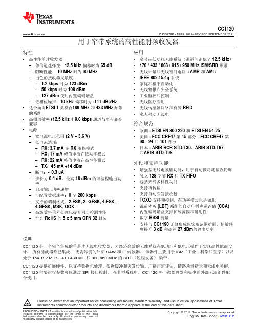
Digital Input/Output
General purpose IO
Power
3 V VDD to internal digital regulator
Power
Digital regulator output to external C
Digital Input
Serial data in
• 增强型无线电唤醒功能,用于自动低功耗接收轮询 • 独立 128 字节 RX 和 TX FIFO • 包括天线多样性功能 • 支持再传输 • 支持自动应答接收包 • TCXO 支持和控制,在功率模式也是如此 • 说前先听 (LBT) 系统的自动广播声道评估 (CCA) • 内置编码增益支持扩展范围和耐用性 • 数字 RSSI 测量 • 支持与 CC1190 无缝集成以实现范围扩展,使敏感
• 适合面向ETSI 1 类符合169 MHz 和 433 MHz 频带 的系统
• 高频谱效率 (12.5 kHz时 9.6 kbps 通道与窄带命令 兼容
• 电源 – 宽电源电压范围 (2 V – 3.6 V) – 低电流消耗: – RX: 3.7 mA 在 RX 嗅探模式 – RX: 17 mA 峰值电流在低功率模式 – RX: 22 mA 峰值电流在高性能模式 – TX:45 mA +14 dBm – 断电:< 0.3 µA – 步长为 0.4 dB、最高 16 dBm 的可编程输出功 率 – 自动输出功率递增 – 可配置数据速率:0 至 200 kbps – 支持的调制格式:2-FSK, 2- GFSK, 4-FSK, 4-GFSK, MSK, OOK – 高级数字信号处理以提升同步检测性能 – 符合 RoHS 的 5 x 5 mm QFN 32 封装
智能开关控制器
LT-0410K智能开关控制器用户手册北京星光莱特电子有限公司BEIJING STARLIGHT ELECTRONICS CO.,LTD 北京市大兴区西红门镇星光巷7号 100076 交货-拆包安全知识操作电缆注意事项主要功能产品特性产品安装和要求控制器的安装环境要求控制器的安装尺寸要求控制器的固定和安装电源线的连接主供电网络形式供电电缆接线要求接线端口供电系统输出连接控制信号的连接方式及走线要求协议简介:DMX512/1990协议简介:LT-NET控制电缆连接标准工作状态及方式的选择各类检测、保护及恢复方法交货-拆包当您收到LIGHTSPACE®的产品时,请确认包装尚未拆卸,并仔细检查设备是否完好;所有设备是经严格检验,并确认完好才允许出厂的;如果发现设备有任何损坏,请及时联系相关人员,并记录在案。
核对您收到的产品和系列产品规格与清单上的是否一致;检查您收到的设备的型号、数量与交付单上的是否一致;一旦发现错误,立即与发货方联系并说明情况,直到收到满意答复。
确认无误后,把产品放回包装,置于符合存储条件的位置,等待最后的安装。
安全知识LT-0410K是专业的智能开关控制器。
符合欧洲安全标准:EN60439,EN60950,它属于Ⅰ类设备,按EN 60439设计生产,按当地规格强制安全接地。
为避免任何触电事故,请不要打开产品外壳和防护措施,正常操作无需了解设备内部情况。
如设备有损坏,必须由专业人员检查和维修。
在检查和维修之前请确认电源已切断。
警告!!!内有致命电压!注意您的安全!安装调试和维修服务应由专业人员操作!任何人员使用前,务必仔细阅读此手册,并按照要求使用。
操作电缆注意事项供电电缆和连接器是设备安全的重要组成部分。
z电缆供电端必须有主断路器、保险器等,用于切断电源,并且不能触碰到电缆;z安装或日常检查时,要确保电缆和连接器无任何损坏;z电缆和信号线不能置于一处。
主要功能z4个开关量输出,每通道10Az每通道有一个10A小型断路器和一个旁路直通开关z应用于分布式智能灯光控制系统z双接口输入,可接收LT-NET信号和DMX-512信号z系统输出一组12V直流电压,供给控制系统使用z电源LED指示及通讯LED指示各一个z可预置场景128个z可分区域128个z渐变时间:1~100秒z可以控制节能灯及日光灯,气体放电灯产品特性电子控制:全数字、微处理器控制额定功率:控制器连续工作额定负荷:4 x 2 kWLT-0410K 最大整机负荷为8 kW工作温度范围:0℃到 40℃。
芯科科技 Si1120 配有 PWM 输出的接近光 环境光感应器 数据表
初步修订 1.0 8/10© 2010 年由Silicon Laboratories 版权所有Si1120本资料适用于正在研发的产品。
产品的特性及规格如有变更,恕不另行通知。
特征应用描述Si1120 是一款低耗能、反射型接近光及环境光感应器,配有先进的模拟信号处理及模拟 PWM 输出。
包括集成型分化光电二极管、信号处理器及LED 驱动。
接近感应乃基于测量外部、光隔离及选通的 LED 的反射光。
环境光感应中使用的是一个单独的可见光光电二极管。
Si1120 的标准包装是8 针脚 ODFN 。
⏹典型的带有单脉冲的 50 cm 接近范围计量表⏹七种精确的测光模式:● 3 种接近范围● 3 dc 环境范围● 1 种校准模式⏹低噪音环境补偿电路敏感度最大可达 8-12 位的分辨率⏹ALS 可直接在阳光下工作 (100 klux)⏹最小反射敏感度小于1µW/cm 2⏹无需隔离包装即可具有较高的 EMI 防御能力⏹供电:2.2-3.7 V⏹操作的温度范围:-40 至 +85 °C ⏹通常为 10 μA 的电流消耗⏹可设计的 LED 恒电流驱动输出 400/50 mA⏹允许独立的 LED 供电⏹3 x 3 mm 的小巧外观 (ODFN)⏹听筒⏹无需触摸式开关⏹占用感应器⏹客户的电子设备⏹笔记本电脑/个人电脑⏹工业自动化⏹显示背光控制⏹光断续器美国专利号 5,864,591美国专利号6,198,118其他正在审批的专利Si1120功能结构图图 1:Si1120 配有 C8051F931 MCU 及 I2C 界面的独特数字接近光及环境光感应器应用范例Si11201.03目录章节页码1. 电气规格 . . . . . . . . . . . . . . . . . . . . . . . . . . . . . . . . . . . . . . . . . . . . . . . . . . . . . . . . . . . . . . . . .42. 应用资料 . . . . . . . . . . . . . . . . . . . . . . . . . . . . . . . . . . . . . . . . . . . . . . . . . . . . . . . . . . . . . . . . .62.1. 操作理论 . . . . . . . . . . . . . . . . . . . . . . . . . . . . . . . . . . . . . . . . . . . . . . . . . . . . . . . . . . .62.2. 模式选择 . . . . . . . . . . . . . . . . . . . . . . . . . . . . . . . . . . . . . . . . . . . . . . . . . . . . . . . . . . .72.3. 接近模式 . . . . . . . . . . . . . . . . . . . . . . . . . . . . . . . . . . . . . . . . . . . . . . . . . . . . . . . . . . .82.4. 环境光模式 . . . . . . . . . . . . . . . . . . . . . . . . . . . . . . . . . . . . . . . . . . . . . . . . . . . . . . . .112.5. LED 和LED 电流的选择 . . . . . . . . . . . . . . . . . . . . . . . . . . . . . . . . . . . . . . . . . . . . . .142.6. 电源瞬变 . . . . . . . . . . . . . . . . . . . . . . . . . . . . . . . . . . . . . . . . . . . . . . . . . . . . . . . . . .142.7. 实际考虑 . . . . . . . . . . . . . . . . . . . . . . . . . . . . . . . . . . . . . . . . . . . . . . . . . . . . . . . . . .153. 针脚说明—Si1120 (ODFN) . . . . . . . . . . . . . . . . . . . . . . . . . . . . . . . . . . . . . . . . . . . . . . . . .164. 订购指南 . . . . . . . . . . . . . . . . . . . . . . . . . . . . . . . . . . . . . . . . . . . . . . . . . . . . . . . . . . . . . . . .175. 光电二极管中心 . . . . . . . . . . . . . . . . . . . . . . . . . . . . . . . . . . . . . . . . . . . . . . . . . . . . . . . . . .176. 封装外形图 (8 针ODFN) . . . . . . . . . . . . . . . . . . . . . . . . . . . . . . . . . . . . . . . . . . . . . . . . . . .18文件更新一览表 . . . . . . . . . . . . . . . . . . . . . . . . . . . . . . . . . . . . . . . . . . . . . . . . . . . . . . . . . . . .19联络资料 . . . . . . . . . . . . . . . . . . . . . . . . . . . . . . . . . . . . . . . . . . . . . . . . . . . . . . . . . . . . . . . . . .20Si11201. 电气规格表1:绝对值最大等级*参数条件最小值特有值最大值 单位供电电压–0.3— 5.5V 操作温度–40—85°C 存储温度–65—85°C TXO 上的 GND 电压–0.3— 5.5V 所有其他针脚上的 GND 电压–0.3—VDD + 0.3V (当 TXO 激活时) 通过 TXO 的最大总电流——500mA 通过 TXGD 及 VSS 的最大总电流——600mA 通过所有其他针脚的最大总电流——100mA ESD 等级人体模型——2kV*注: 如使用负荷超过上表所列数值可能对设备造成永久损害。
SR704 AC Current Probe操作手册说明书
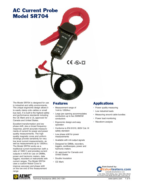
AC Current Probe Model SR704The Model SR704 is designed for use in industrial and utility environments. The unique ergonomic design allows it to easily clamp onto cables or small bus bars. It is built to the highest safety and performance standards including the CE Mark and is UL approved for Canada and United States.Excellent transformation and low phase shift, plus a broad frequency response, permit accurate measure-ments of current for power and power quality measurements. The high quality magnetic cores and uniform windings provide sensitivity for very low level current measurements, as well as measurements up to 1200A AC. The Model SR704 works as a traditional current transformer (with a ratio of 1000:1) and provides current outputs in mA/A for use on DMMs, power and harmonic meters, data loggers, recorders or instruments with current ranges. The Model SR704 uses a custom Nickel Cove to improve accuracy and phase shifton the low end of the measurement range Features•Measurement range of1mA to 1200A AC•Large jaw opening accommodatesconductors up to two 500MCMconductors•Ergonomic design and easyoperation•Conforms to EN 61010, 600V Cat. IIIsafety standard•Low phase shift for powermeasurements•Available with mA output signals•Designed for DMMs, recorders,loggers, oscilloscopes, power andharmonic meters•UL approved for Canada andUnited States•Double Insulation•CE MarkApplications•Power quality measuring•Low industrial loads•Measuring around cable bundles•Power load monitoring•Waveform analysisSpecificationsMODEL SR704*Nominal Range1000AMeasurement Range1mA to 1200ATransformation Ratio1000:1Output Signal1mA AC/A AC(1A AC@ 1000A)Accuracy (1000A Range)1mA to 100mA≤3% of Reading ±5µV0.1 to 1A≤2% of Reading ±3µV1 to 10A<1% of Reading ±0.2mV10 to 100A≤0.5% of Reading100 to 1200A≤0.3% of ReadingPhase Shift (1000A Range)1 to 10A≤2°10 to 100A≤1°100 to 1200A≤0.7°Overload1200A for 40 min ON,20 min OFFFrequency Range30Hz to 5kHz;current deratingabove 1kHz usingthe formula:Load Impedance5ΩmaxWorking/Common600Vrms Cat. IIIMode VoltageOutput Termination 5 ft LeadOperating Temperature-14°to 122°F (-10°to 50°C)Storage Temperature-4°to 158°F (-20°to 70°C)Operating Relative0 to 85% @ 35°CHumidityJaw Opening 2.25" (57mm) maxMaximum Conductor Size 2.05" (52mm)Maximum Bus Bar Size One 1.95 x 0.19" (50 x 5mm)Dimensions 4.37 x 8.50 x 1.77" (111 x 216 x 45mm)Weight 1.21 lbs (550g)Polycarbonate Material Handles: Polycarbonate + ABS, Gray, UL94 V0. Jaws: Polycarbonate, Red, UL94 V0 Electrical EN 61010-2-032UL Approval Yes – Canada and United StatesDouble Insulation YesCE Mark YesNote:Reference conditions:23 ±3°K, 20 to 75% RH, 48 to 65Hz, external magnetic field <40A/m, no DC component, no external current carrying conductor,test sample centered.Load impedance 5Ω.*Diode Protection for open secondary (Output)CATALOG NO.AC Current Probe Model SR704 (Lead – 1mA/A – 1000A max). . . . . . . . . . . . . . . . . . . . . . . . . . . . . . . . . . . . . . Cat.#2116.30Includes a user manual Accessories (Optional)Banana (Female) – BNC (Male) Adaptor. . . . . . . . . . . . . . . . . . . . . . . . . . . . . . . . . . . . . . . . . . . . . . . . . . . . . . . . . . Cat. #2118.464.37" (111mm)3.98" (101mm)2.25" (57mm)8.50" (216mm)1.71" (43.5mm)3.90" (99mm)2.13" (54.1mm)1.22" (31mm)1.38" (35mm)1.77"(45mm)Black RedØ=2.05" (52mm)Conductor sizemax.Leads:Double/reinforced 5 ft (1.5m) lead with safety 4mm banana plugContact UsUnited States an d Canada:Chauvin Arnoux®, Inc.d.b.a. AEMC®Instruments200 Foxborough Blvd.Foxborough, MA02035 USA(508) 698-2115 • Fax (508) 698-2118Customer Support – for placing an order, obtaining price and delivery:************************Sales Department – for general sales information:**************Repair and Calibration Service – for information on repair and calibration, obtaining a user manual: ***************Technical and Product Application Support – for technical and application support:*****************Webmaster – for information regarding :******************South America, Central America, Mexico, Caribbean, Australia an d New Zealand:Chauvin Arnoux®, Inc.d.b.a. AEMC®Instruments15 Faraday DriveDover, NH 03820 USA(978) 526-7667 • Fax (978) 526-7605***************All other countries:Chauvin Arnoux SCA190, rue Championnet75876 Paris Cedex 18, France33 1 44 85 45 28 • Fax 33 1 46 27 73 89***********************。
STC-700系列工业机器人视觉相机说明书
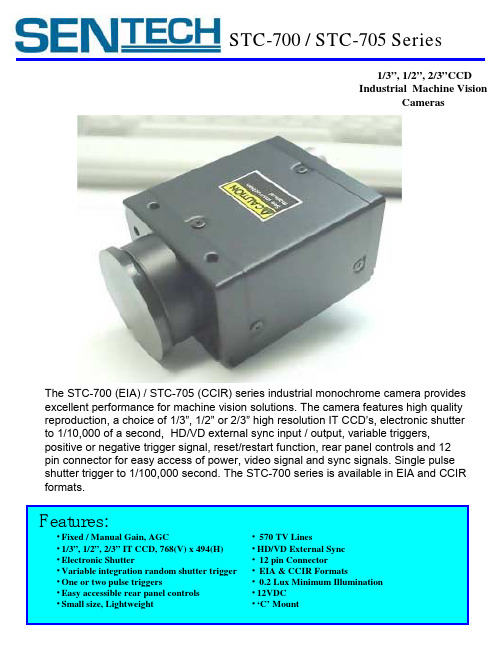
STC-700 / STC-705 Series1/3”, 1/2”, 2/3”CCDIndustrial Machine VisionCamerasThe STC-700 (EIA) / STC-705 (CCIR) series industrial monochrome camera provides excellent performance for machine vision solutions. The camera features high quality reproduction, a choice of 1/3”, 1/2” or 2/3” high resolution IT CCD’s, electronic shutterto 1/10,000 of a second, HD/VD external sync input / output, variable triggers,positive or negative trigger signal, reset/restart function, rear panel controls and 12pin connector for easy access of power, video signal and sync signals. Single pulse shutter trigger to 1/100,000 second. The STC-700 series is available in EIA and CCIR formats.Features:•Fixed / Manual Gain, AGC•1/3”, 1/2”, 2/3” IT CCD, 768(V) x 494(H)•Electronic Shutter•Variable integration random shutter trigger •One or two pulse triggers•Easy accessible rear panel controls •Small size, Lightweight •570 TV Lines•HD/VD External Sync•12 pin Connector•EIA & CCIR Formats•0.2 Lux Minimum Illumination •12VDC•‘C’ MountSTC-700/705 Series Industrial CamerasTechnical Specifications STC-700 / STC-705Model: STC-700 STC-705 STC-720 STC-725 STC-730 STC-735 CCD Size: 2/3” 2/3” 1/2” 1/2” 1/3” 1/3”Effective Pixel: 768 x 494 752 x 582 768 x 494 752 x 582768 x 494 752 x 582 Chip Size: 10.25 x 8.5 10.25 x 8.5 7.95 x 6.45 7.95 x 6.45 6.00 x x 4.96 6.00 x 4.96 Cell Size:11.6 x 13.5 11.6 x 11.2 8.4 x 9.8 8.6 x 8.30 6.35 x 7.40 6.50 x 6.25 Scan Size: 8.91 x 6.67 8.72 x 6.52 6.45 x 4.84 6.47 x 4.83 4.88 x 3.66 4.89 x 6.39 Signal Format: EIA CCIR EIA CCIR EIA CCIRHorz Freq(KHz) 15.734 15.625 15.734 15.625 15.734 15.625Vert Freq.(Hz) 59.94 50.00 59.94 50.00 59.94 50.00Horz Resolution: 570 560 570 560 570 560Lens Mount: C-MountSync. System: Internal or External (Auto detect of HD input pulse at ‘Ext. Position’ of the sync switch) Ext. Sync. Signal: HD/VD (H:2~5V, L;0~0.6V), 15.734KHz±1.0% (EIA) 15.625KHz ±1.0% (CCIR)Input impedance switchable (75Ωor high impedance) for HD/VD Scanning System: 2:1 Interlace (Internal Sync.)S/N Ratio:56db at zero gainGamma Correction: On (0.45) / Off (1.0)Integration Mode: Frame or FieldElectronic Shutter: 1/250, 1/500, 1/1000, 1/2000, 1/4000, 1/10000 (EIA)Flickerless: 1/100 (EIA), 1/120 (CCIR)Gain: AGC (0-20db), Manual (POT on rear panel) / Fixed at 13dbRandom Shutter Trigger x 3: Fast 1/100,000 second electronic shutter w/ one pulse variable integrationrandom shutter trigger(reset or non-reset).Two pulse variable integration random trigger (reset or non-reset)Fixed Integration random shutter trigger (reset or non-reset)Ext. Trigger Signals: Positive / Negative modes H level=3~5V, L Level=0~0.6VReset / Restart: Integration time controlled by external VD (requires ext. HD and VDWEN:Active high, H level=3~5V, L level=0~0.6VPower Input: 12VDC (10.5~15V)Power Current: 220mA(STC-700), 180mA(STC-720), 175mA(STC-730), 170mA(STC-700E) Operating Temp: -5°C~+45 °C 20~80% (No Condensation)Storage Temp: -30°C~+60°C 20~80% (No Condensation)Spec. Guarantee Temp. Range: 0°C~+40°CVibration: 10G (20~200Hz)Shock: 70GSize: 44(W) x 29(H) x 72.7(D) From C-Mount to 12 Pin ConnectorWeight: 97g*Note-All Specifications can change without notice.12 Pin Connector PinoutPin No. Int. Sync. Ext. Sync Ext. VS Trigger 1 Ground Ground Ground Ground 2 +12VDC +12VDC 12VDC +12VDC 3 Ground Ground Ground Ground 4 Video Video Video Video 5 Ground Ground Ground Ground 6 IID Out IID In ---------IID In 7 VD Out VD In VS In VD In 8 Ground Ground Ground Ground 9 --------------------------S-Trig In10 --------------------------WEN Out11 --------------------------Trig In12 Ground Ground Ground GroundSTC-700 Series Rear Panel ViewOnOff1. 12 Pin Hirose Connector2. BNC Video Connector3. Sync Switch: Internal, External HD/VD4. 75 Ohm Termination5. Gain mode: A=AGC F=Fixed M=Manual6. Manual Gain VR7. Gamma 0.45 or 1.08. Shutter Speed Selection9. Dip Switch Mode Selection (See chart)10.Trigger Polarity (positive/negative)1.2.3.4.10.5.6.7.8.9.DIP SwitchNo..ON OFF 1Field integration Frame integration 2Normal operation Trigger operation3Fixed integration random shuttertrigger Variable integration random shuttertrigger 4One pulse variable integration random shuttertriggerTwo pulse variable integration random shuttertrigger 5None-reset mode Reset mode 6None restart/resetRestart/resetMode Selection Dip Switches:1015 North I-35E #206 Carrollton, TX 75006Phone: 972-245-4243 Fax: 972-446-0056Toll Free 877-736-8324 (877-SENTECH)Website: Sensor Technologies America IncModes of Operation:•Normal Mode, Field Integration •Normal Mode, Frame Integration•One Pulse Variable Integration Random trigger (reset)•One Pulse Variable Integration Random trigger (non-reset)•Two Pulse Variable Integration Random •trigger (reset)•Two Pulse Variable Integration Random trigger (non-reset)•Fixed Integration Random Shutter Trigger (reset)•Fixed Integration Random Shutter Trigger (non-reset)•Reset / Restart, Field Accumulation •Reset / Restart, Frame Accumulation * See Application Manual for details。
东莞市精心自动化设备 转盘式自动锁螺丝机k704 说明书
PDF 文件使用 "pdfFactory Pro" 试用版本创建 Аö
KINGSUN 东莞市精心自动化设备科技有限公司
Kingsun Automa o T n echnol o (D gy ongGuan) C L o. td
转盘式自动锁螺丝机 K704 说明
机器突出特点:
1.
通过多工位的转盘实现夹具循环圆周步进流水作 业,放产品、组装、检测、锁螺丝、卸料等工序同 步进行,机器效能大大提升;
KINGSUN 东莞市精心自动化设备科技有限公司
Kingsun Automa o T n echnol o (D gy ongGuan) C L o. td
使用寿命,确保机器长时间不间断稳定运行…
機械舉升式自动送螺钉机参数
螺丝盘容积: 2000PCS(以 M3X8 标准螺丝为例) 总长尺寸>1.3 螺丝头直径 适用螺丝: 牙部直径:M1.7--M6mm(任选一种) 螺丝长度:25mm 以内 螺絲材料:任何材料 K101(1 条管道) 效率 K102(2 条管道) K103(3 条管道) K104(4 条管道) 螺釘输送方式: 电 气 体 源: 压: 积: K101(1 条管道) 重量 K102(2 条管道) K103(3 条管道) K104(4 条管道) 螺丝输送距离: 60PCS/MIN 30pcs/min/每条管道(同時吹送 2 顆螺絲) 20pcs/min/每条管道(同時吹送 3 顆螺絲) 20pcs/min/每条管道(同時吹送 4 顆螺絲) 用透明软塑胶管输送螺丝 AC220V 50HZ 5kg/cm 20kg 22kg 23kg 28kg 4 米以上,機器可摆放在台面下 带计数功能,显示产量,可清零可设定 调节吹送螺丝时间; 液晶显示屏功能: 调节機器休眠时间; 可以调节为自動循環作業; 缺料,漏料和料的报警显示; 螺丝送料检测: I/O 信号 噪 音: 两对传感器检测螺丝 DC 24V 可与锁螺丝机通讯 输入输出信号可采集 平均 65dB 最大瞬間 80dB 模具钢精细加工淬火研磨 模具钢精细加工淬火研磨 模具钢精细加工研磨电镀 铝合金材料
