sp10说明
斯金丝精密公司SP10战术狙击步枪

斯金丝精密公司SP10战术狙击步枪近来,战术狙击步枪市场竞争愈发激烈,曾推出优秀轻量级卡宾枪的斯金丝精密公司也积极进入战术狙击步枪市场,在2016年推出一款半自动战术狙击步枪,这就是SP10战术狙击步枪――两年磨一枪斯金丝精密公司在2016年推出SP10战术狙击步枪,但其实研发早在两年前就开始着手了。
经过两年多的研发和测试才于2016年推向狙击步枪市场,由此可见斯金丝精密公司对这款SP10战术狙击步枪十分重视。
铝合金护手侧面特写,其上设有诸多散热孔,其中钥匙状散热孔兼作导轨安装孔SP10战术狙击步枪是一款口径为7.62mm的半自动狙击步枪,采用M16步枪的结构,枪管长457mm,采用伸缩式枪托,枪托完全伸长时全枪长1016mm,枪托缩进后全枪长933mm,非常便于携行。
其发射7.62mm北约制式枪弹,弹匣容弹量为20发。
铝合金护手底部特写,可见中心线上设有钥匙状孔,既可散热又兼作导轨安装孔,此外,两侧另有6对斜向散热孔近观SP10机匣下机匣由标准的7075-T6号铝合金打造而成,其外形与普通M16的上下机匣并不完全相同,并且机匣表面都进行了三级阳极电镀。
上机匣采用平顶式设计,上机匣右侧的辅助推机柄被取消。
抛壳窗后面的导弹板加大。
枪机组件为军规标准,后面的拉机柄也是加大设计。
下机匣采用增强型设计。
下机匣两侧均设有弹匣卡笋和空仓挂机解脱杆,保险也是两侧都有设置,这样就能满足左右手不同习惯的射手,十分具有战术性。
扳机护圈明显加大,使射手戴着手套也能轻松扣动扳机。
配用斯金丝精密公司设计制造的CMC扳机系统,加工十分精密,可靠性极高。
ATC枪口制退器设计十分独特,在正面中间除了枪口的大孔外,周围均布8个小孔枪管SP10战术狙击步枪采用457mm长枪管,在长度上既满足了射程的需求,又方便携带。
为了保证精度,选用了比赛级不锈钢枪管,这样的配置也是战术狙击步枪的标配,并且银色枪管十分漂亮。
枪管与护手不接触,为自由浮置式设计,有助于提高射击精度。
NACE标准 SP10 中文版
NACE标准SP10 中文版SSPC:保护涂层协会接口表面处理说明书SSPC-SP 10/NACE NO. 2近白喷砂处理SSPC:SSPC和NACE国际标准紧代表审阅过本文献并就它的适用范围和规定达成一致的个别成员。
不管是否采纳该标准,此次达成的一致不会在任何方面排除在制造、销售、购买及产品、程序的使用上不符合该标准的人。
该标准没有以暗示或其他任何方式授权制造、销售或使用任何专利保护的方法、设备、或产品以及赔偿或保护任何侵犯专利权的个人。
该标准代表最低要求并且不会限制更好的程序和材料的使用。
该标准并不适用所有或相关领域。
不可预知的环境因素可能会使该标准在特定的情况下失效。
SSPC和NACE对该标准的官方解释负责,但对于其他组织或个人对于该标准的解释不负任何责任。
在使用该标准之前,用户可以通过这一标准负责检查确保适当的健康、安全和规范性文件并确定关于该标准的适用性。
SSPC/NACE不必要列出所有与材料、设备使用,操作细节相关的以及标准自身存在的潜在的健康安全问题和环境事故。
必要时,用户负责咨询有关当局来建立一套合适的健康、安全、环保体系来适应现有的规范性要求。
注意:SSPC/NACE标准受定期检查的影响而且可能在不预先通知的情况下被修订或撤回。
SSPC/NACE要求在第一版发行的五年内进行重申、修订或撤销。
建议用户获取最新版本。
买方可以联系以下机构来得到所有标准和其他出版物的最新消息:德克萨斯州休斯敦市南港1400号NACE电话:+1 281/228-2600邮编:77084-4906宾夕法尼亚州匹兹堡市40 24大街SSPC六楼电话:+1 412/281-2331邮编:15222前言该标准涵盖了喷丸处理磨料的使用以实现在应用保护性涂料或衬里系统前给钢铁表面清理程度明确的定义。
该标准的目的是用于涂层或衬里说明符、敷料器、检查员或其他负责人,来定义一个表面清洁度的标准程度。
该标准的重点在于近白色金属喷抛清理。
SSPC-SP NO.10

表面处理标准SSPC-SP NO. 10/NACE NO.2赤白色喷砂清洁度1.概述1.1此联合标准覆盖了使用研磨剂的非油漆及油漆面的赤白色喷砂清洁度要求。
这些要求包括了材料或表面应达到的最终清洁条件,及必要的工艺以达到及验证这个最终的条件。
1.2此联合材料允许单元表面上存在在2.6SECTION中所定义的百分之五的以下的污物。
1.3强制要求在以下面的SECTION 1到9中进行了说明。
SECTION 1 概述SECTION 2 定义SECTION 3 参考SECTION 4 喷砂前的流程SECTION 5 喷砂方法及操作SECTION 6 喷砂磨料SECTION 7 喷砂清洁及直接涂层流程SECTION 8 检验SECTION 9 安全及环境要求2.定义2.1 赤白金属喷砂表面,在无放大镜辅助的情况下,表面无可视油脂,灰尘,氧化皮,锈蚀,涂层,氧化物,产品腐蚀等其它杂志,除2.2中所描述的其他污物外。
2.2 单独区域表面污物应按2.6中所要求的控制在百分之五以内,它们包括少量的shadows, 轻微的streaks,或是由锈蚀造成的较小的色差,氧化皮的残留物或是在涂层前所出现的污迹。
2.3 不影响表面清洁度的可接受的外观变化见SECTION 2.1,包括由金属类型,原始表面条件,金属厚度,焊接用金属,拼装标识,热处理,热影响区,喷砂磨料及由不是同一批喷砂所形成的差异性。
2.4 当有涂层要求时,表面粗糙度必须满足涂层体系要求。
2.5 在直接涂层前,整个表面须满足此处所要求的清洁度。
2.6 单独区域应至少有5776平方米(如:76x76平米)2.7 SSPC-VIS 1-89 图片A SP-1-,B SP-10, C SP-10 或 D SP-10 可作为此定义的辅助文件。
在存在争议的情况下,文字性标准优先与视检标准。
其它相关的视检标准信息及对比表可以附件A中的Section A.4中看到。
3.参考3.1 此文件中所涉及的标准列在Section 3.4中3.2 最新下发版本或所涉及相关标准的改版shall govern 除非另有说明3.3 如果此标准中所涉及的相关标准与本标准相冲突,以此标准为准。
SSPC-SP NO.10

表面处理标准SSPC-SP NO. 10/NACE NO.2赤白色喷砂清洁度1.概述1.1此联合标准覆盖了使用研磨剂的非油漆及油漆面的赤白色喷砂清洁度要求。
这些要求包括了材料或表面应达到的最终清洁条件,及必要的工艺以达到及验证这个最终的条件。
1.2此联合材料允许单元表面上存在在2.6SECTION中所定义的百分之五的以下的污物。
1.3强制要求在以下面的SECTION 1到9中进行了说明。
SECTION 1 概述SECTION 2 定义SECTION 3 参考SECTION 4 喷砂前的流程SECTION 5 喷砂方法及操作SECTION 6 喷砂磨料SECTION 7 喷砂清洁及直接涂层流程SECTION 8 检验SECTION 9 安全及环境要求2.定义2.1 赤白金属喷砂表面,在无放大镜辅助的情况下,表面无可视油脂,灰尘,氧化皮,锈蚀,涂层,氧化物,产品腐蚀等其它杂志,除2.2中所描述的其他污物外。
2.2 单独区域表面污物应按2.6中所要求的控制在百分之五以内,它们包括少量的shadows, 轻微的streaks,或是由锈蚀造成的较小的色差,氧化皮的残留物或是在涂层前所出现的污迹。
2.3 不影响表面清洁度的可接受的外观变化见SECTION 2.1,包括由金属类型,原始表面条件,金属厚度,焊接用金属,拼装标识,热处理,热影响区,喷砂磨料及由不是同一批喷砂所形成的差异性。
2.4 当有涂层要求时,表面粗糙度必须满足涂层体系要求。
2.5 在直接涂层前,整个表面须满足此处所要求的清洁度。
2.6 单独区域应至少有5776平方米(如:76x76平米)2.7 SSPC-VIS 1-89 图片A SP-1-,B SP-10, C SP-10 或 D SP-10 可作为此定义的辅助文件。
在存在争议的情况下,文字性标准优先与视检标准。
其它相关的视检标准信息及对比表可以附件A中的Section A.4中看到。
3.参考3.1 此文件中所涉及的标准列在Section 3.4中3.2 最新下发版本或所涉及相关标准的改版shall govern 除非另有说明3.3 如果此标准中所涉及的相关标准与本标准相冲突,以此标准为准。
丙烯酸聚氨酯面漆 说明书

性能特点
基材*:钢材 表面处理*:SSPC-SP10 测试系统*: 1 层 Macropoxy 646 环氧中层漆 150微米 干膜厚度 1 层 Acrolon 218 HS 高光面漆 100微米 干膜厚度
*除非另有说明,以下数据均由此系统获得
不稀释 : 稀释10% : 稀释15% :
测试名称 耐磨性 附着力 腐蚀环境 抗直接冲击 抗干燥环境温度 延展性
5.22
施工指南
表面处理 施工条件
温度: 最低4°C,最高49°C (空气、被涂表面和涂料) 至少高于露点2.8°C 最大为85%
为了确保足够的附着力,被涂物表面必须清洁、干燥和坚固。除 去所有的油、灰、脂、污垢、松动的锈层和其他外部附着物。 铁和钢材表面: 按照SSPC-SP1先用溶剂除去被涂表面的油脂,最低的喷砂处理等 级要求是SSPC-SP6/NACE3规定的商业喷砂处理。 要想获得更好 的效果,应该按照SSPC-SP10/NACE2使用有棱角锐利的金属磨料 对所有表面进行近似出白喷砂处理,最佳表面粗糙度为 (25-50 微 米)。应在表面处理的当天和裸露的金属表面产生闪锈前涂装底漆。 铝材表面: 按照SSPC-SP1的标准清除所有的油、脂、污物和其它的金属氧化 物。必须施工底涂。 镀锌钢材表面: 被涂镀锌钢材至少应在自然环境中老化6个月后才可进行涂装。 按 照SSPC-SP1先用溶剂对被涂表面进行清洗。如果没有经过自然老 化或者被涂表面经过铬酸盐或硅酸盐处理,按照SSPC-SP1先用溶 剂对被涂表面进行清洗,然后进行局部涂装试验。待其干燥至少一 星期后进行附着力测试。如果附着力差,则应该按照SSPC-SP7进 行扫砂处理,除去原有涂层。如果被涂表面电镀层出现锈蚀,至少 应当按照SSPC-SP2进行一次手工工具清理,并在当天或闪锈锈产 生前涂装底漆。 浇注混凝土表面: 新的表面 按照SSPC-SP13/NACE 6的标准或ICRI03732,CSPI-3进行表面 处理.被涂表面必须干燥、清洁,密实,以保证良好的附着力。最少 在 24°C温度下保养28天,去除所有松散的灰浆和外来物质表面必 须清除泥浆、混凝土灰尘、污垢、脱膜剂、水汽固化膜、松散的水 泥和固化剂,用Steel-Seam FT910来填补孔洞、气孔裂缝等瑕疵。 通常参照以下标准: ASTM D4258标准用于清洁混凝土。 ASTM D4259标准用于打磨混凝土。 ASTM D4260标准用于蚀刻混凝土。 ASTM F1869标准用于测量混凝土的水蒸气通过率。 SSPC-SP 13/Nace 6是混凝土表面处理标准。
A6 5.1 SP10升级包补丁说明

生产执行 委外管理 委外管理 委外管理 销售管理 销售管理 销售管理 销售管理 销售管理 销售管理 销售管理 销售管理 销售管理 销售管理 销售管理
97 98 99 100 101 102 103 104 105 106 107 108 109 110 111 112 113 114 115 116 117 118 119 120 121 122 123 124 125 126 127 128 129 130 131 132 133 134
支持系统33949 支持系统34590 支持系统34017 支持系统33572 支持系统34817 支持系统34161 支持系统33950 支持系统34261、 34381 支持系统34319 支持系统34328 支持系统34174、 34363 支持系统34188、 33786、33646、 33328 支持系统34120 支持系统34126 支持系统34011
67 68 69 70 71 72 73 74 75 76 77 78 79
软件Bug 软件Bug 打印问题 改进建议 新增需求 新增需求 数据问题 改进建议 改进建议 软件Bug 软件Bug 软件Bug 软件Bug
支持系统33750 支持系统33841 支持系统33492 支持系统33231 支持系统33551 支持系统33153 支持系统33174 支持系统32837 支持系统33033 支持系统34160 支持系统34179 支持系统34507 支持系统
135 136 137 138 139 140 141 142 143 144 145 146 147 148 149 150 151 152 153 154 155 156 157 158 159 160 161 162求 改进建议 数据问题 改进建议 数据问题 改进建议 软件Bug 打印问题 软件Bug 软件Bug 软件Bug 改进建议 软件Bug 改进建议 软件Bug 软件Bug 软件Bug 软件Bug 软件Bug 新增需求 软件Bug 软件Bug 改进建议 改进建议 数据问题 软件Bug 软件Bug 数据问题 改进建议 数据问题 接口问题 软件Bug
Sysmex XN系列和SP-10维护指南说明书

Sysmex XN Series and SP-10 MaintenanceDocument Number: RHEAHS14010MUL Revision Number: 2.50 Document Type: Procedure Effective Date: 6/17/2022 2:26:04 PM Location: 3. APL Folder Structure\Hematology HE\CBC and Differential\Sysmex XN - 59\Edmonton ZoneRHEAHS14010MUL Sysmex XN Series and SP-10 MaintenanceAPPLICABILITYThis document is applicable to APL staff at the following Edmonton Zone sites: GNH,RAH, SGH and UAH.PURPOSEThis procedure describes how to perform the daily clean, shutdown, startup and maintenance (daily, weekly and monthly) of the Sysmex XN series and SP-10 analyzers.MATERIALSPROCEDURE4.1. XN Series MaintenanceAll maintenance procedures must be signed off on the Sysmex XN Series Maintenance form.4.1.1. Daily4.1.2. Weekly4.1.3. Monthly4.1.4. Every Six Months4.1.5. Yearly or As Needed4.2. SP-10 Maintenance (RAH and UAH only)All maintenance procedures should be signed off on the Sysmex SP-10 Maintenance form.4.2.1. DailyWhen in shutdown, remove the trap chamber from the right side of4.2.2.Weekly4.2.3.As NeededREFERENCES1. Sysmex XN-1000 / XN-2000 Automated Hematology Analyzers CLSI Procedure, Document number:1004-LSS. Rev. 1, March 20132. XN Series (For XN-1000 system) Instructions for Use (North American Edition), November 2012.3. SP-10 Instructions for use.4. XN-9000 Instructions for use.RELATED DOCUMENTSRHEAHF14010MULA Sysmex XN Series MaintenanceRHEAHS14006MUL Sysmex XN Series - Performing QCRHEAHS14019MUL Sysmex XN Series - Manual Shutdown and StartupRHERHS00004MUL Inter-Instrument Variability for Hematology Coagulation and Special Coagulation AnalyzersRHERHF00002MUL Hematology Inter-Instrument Variability Excel WorksheetRQMPCS14000MUL Annual Autovalidation CheckRHEAHF14010MULB Sysmex SP-10 MaintenanceHE24-097 Evaluating Quality Control using the Beyond Care Quality Monitoring BCQM System。
PowerMILL 2016 SP10 破解说明
7.输入 C:\Windows\System32\drivers\multikey.sys 点OK
8.点Exit
9.按Next
第四步:
右键以管理员身份运行“4.RemoveWatermarkX64.exe”。输入 Y 并按回车键,运行完成后关闭。
第二步:
右键以管理ห้องสมุดไป่ตู้身份运行“2.PMCrack.exe”。并按提示进行操作。
第三步:
右键以管理员身份运行“3.64位系统附加操作.exe”。
1.Next
2.Yes
3.点Enable Test Mode
4.Next
5.点Sign a System File
第七步:
重启电脑。ok
第五步:
右键以管理员身份运行“BPatch.exe”。
第六步:
将 “6.替换文件"文件夹中的“pmill.exe”文件复制到PowerMILL 2016 SP10安装目录下(如:D:\Program Files\Delcam\PowerMILL 20.0.10\sys\exec64\)替换原文件。
PowerMILL 2016 SP10 破解说明:
PowerMILL2016及以后版本均只有64位版本,不再支持32位系统。本PowerMILL 2016 SP10 破解支持所有功能(包括多轴)。并且没有只能同时开启2个PM的限制。
安装PowerMILL通常要安装以下模块:
1.PowerMILL2016sp10(主程序)
2.Exchange2016R3(转档模块)
3.DuctPost1516(后处理模块)
当前文件仅为破解文件,以上模块安装文件请另外下载,本破解通用以上模块,其它模块无需另外破解。
SP10肺活量计中文说明书
SP10肺活量计使用说明尊敬的客户,十分感谢您购买使用肺活量计。
在使用本产品前,请务必先行仔细阅读使用说明书,并按照使用说明书相关规定要求执行。
本使用说明书将告诉您在使用本公司产品时必须注意的操作步骤、可能导致异常的操作、可能对本仪器或人身造成伤害的危险。
因未按本使用说明书的要求使用、维护、保管而造成的任何异常现象或人身和机器危险伤害,本公司不承担安全、可靠性及性能保证责任,也不会对此类故障给予免费维修。
由于产品更新,您所得到的产品可能与说明书中描述不完全一致,谨此致歉。
本产品为医疗设备,可以重复使用。
警告:鉴于测试准确性的考虑,对于同一测试者请不要连续测试超过5次。
被测人在测试过程中要一次性呼出全部气体,不要换气、咳嗽。
温度过低时请不要使用本设备。
本机有自动关机功能,若一分钟无操作,则自动关机。
对于有关临床限制和禁忌症的详细内容,请仔细查阅相关医学文献。
本仪器不是一种治疗装置。
本公司保留对本说明书的最终解释权。
目录1 安全 (3)2 概述 (3)2.1产品特点 (4)2.2产品使用范围 (4)2.3环境条件 (4)3 测量原理 (4)4 技术特性 (4)4.1主要性能 (4)4.2主要参数 (5)5安装 (5)5.1前面板简介 (5)5.2安装 (6)5.3产品附件 (6)6 操作向导 (6)6.1使用方法 (6)6.2操作注意事项 (13)7 维护与保养、运输与贮存 (13)7.1清洗消毒 (13)7.2保养 (13)7.3运输与贮存 (13)8 故障分析与排除 (14)9 符号含义 (14)10 参数介绍 (15)1 安全1.1 安全操作说明✧定期检查,确保仪器没有可影响安全或监护性能的明显损坏,建议至少每周检查一次。
若有明显破损,应停止使用仪器。
✧本仪器的维修仅限于由厂家指定的有资格的维修人员进行,用户不要自行维修仪器。
✧本仪器不适用于与除使用说明书中指定的仪器之外的设备一起使用,只有制造商指定或推荐的附件才可以使用。
施耐德泰山SP UPS 10-20KVA 31
1.2 安全注意事项
危险
小心触电、爆炸或电弧 本文档中的所有安全说明必须认真阅读、深入理解并严格遵守。 未按说明操作可能导致人身伤亡等严重后果。
! 小心
小心表示危险状况,如不避免,可能会导致轻度或中度人身伤害。 未按说明操作可能导致人身伤害等严重后果。
注意
注意用于描述不会造成人身伤害的操作。此类安全消息不应使用安全警告符号。 未按说明操作可能导致设备损坏等严重后果。 请注意:电气设备应仅限由有资质的人员来安装、操作、维修和维护工作、对于不按照本手册操作引起的任何 后果,施耐德电气概不承担任何责任。 有资质的人员是指具备电气设备构造、安装和操作的相关技能和知识、接受过安全培训、能够识别并避免相关 危险的人员。
5.0 故障排除.....................................................................................................31 6.0 售后服务.....................................................................................................33 7.0 产品规格.....................................................................................................34
4.0 产品安装与调试..........................................................................................13
SP生产操作规程
SP板生产操作规程第一章:张拉作业1、张拉机安全操作规程1.1、开捆钢绞线前对其标牌进行登记,用剪刀打开钢绞线包装带时不能损伤钢绞线,并同时检查锚具是否完好。
1.2 、在张拉前应安放好防护罩,操作人员必须佩带安全帽。
1.3、将张拉机放置于承压板前面平行位置,并加以稳定。
检查压力表指针是否正常,启动液压泵声音是否有异常。
1.4、按照技术文件要求的张拉参数值张拉钢绞线,并记录好每根钢绞线张拉力值和伸长量 (检验员记录),发现两值参数超过10% 时应住手张拉并汇报技术负责人,采取相应措施后再施张拉操作。
1.5、张拉时床身两端不得停留任何人员,操作人员应站在被张拉钢绞线两侧,严禁与张拉钢绞线成向来线。
1.6、在张拉过程中发现钢绞线有异常声音时应即将停机,操作人员迅速离开拉伸方向,观察是否存在断股现象,通知技术负责人前往处理。
1.7、张拉完毕,切断张拉机电源收线。
清理现场同时将钢绞线标牌交检验员。
2、承压板安装安全操作规程2.1、按照作业产品型号选用承压板、等高块和高强螺栓,将承压板对称放平。
2.2、吊装承压板须将绳钩与吊物调整垂直后方可起吊,保证起吊平稳,平缓移置至安装处。
2.3 、严禁使用破损挂钩和绳套,严禁用手伸入承压板下。
2.4 、认真检查承压板螺栓,对有损伤罗纹不得使用。
2.5、对称扭紧螺栓,用锤击法检查等高块是否垫实,检查承压板与张拉支架端面是否紧贴,否则需要重新调整螺栓。
2.6、作业班组设专人每天对吊具进行吊装前检查,严禁用替代物施吊。
3、张拉机操作步骤3.1、将张拉机放置正确位置。
接通电源后启动油泵,使用相应工作锚具夹紧钢绞线。
3.2、每根钢绞线分二次张拉,第一次张拉力控制在30%摆布,随后拉至设定值。
3.3、张拉时尽量从两边向中间对称张拉。
3.4、张拉应力要控制准确,压力表读数要控制在0.1MPa 误差范围内尽可能使每根钢绞线拉力相等。
3.5、对每根钢绞线要填写张拉记录,并存档备查。
3.6、张拉过程中,采用双控张拉,如浮现张拉值与伸长量且超过规定范围,应汇报主管技术负责人,分析原因后再确定是否再进行张拉。
SSPC-SP10 中文 version
编号 21130联合表面处理标准NACE No. 2/SSPC-SP 10近出白金属喷砂清理本NACE国际(NACE)/美国防腐涂料协会(SSPC)标准是那些审查过其文件、范围和条款的个人会员一致通过后最终确定的版本。
本标准旨在为制造商、消费者和公众提供帮助。
无论其被采用与否,本标准的接受并不排除任何有关制造、销售、采购或使用产品、过程或程序的内容未在本标准中被提及。
本NACE/SSPC标准中所含内容绝非暗示同意任何权利,或制造、销售、或使用拥有专利特许证的任何方法、仪器或产品,或被认作保证或保护任何人不受侵犯专利特许证而因承担的责任。
本标准代表了最新的技术,但绝不能被解释为限制采用更好的程序或材料。
本标准并不适用于与议题有关的所有情况。
在特定情况下,不可预知的情形会影响本标准的有效性。
NACE和SSPC并不承担因其他方解释或使用本标准而引起的任何责任,仅承担由NACE或SSPC按照其受控程序和规则颁布的那些官方解释所产生的责任,但不包括个别志愿者所发布的任何解释。
本NACE/SSPC标准的使用者有责任参阅合适的健康、安全、环保和法规文件,同时,他们也有责任在使用前确定与本标准有关的可应用性。
本NACE/SSPC标准可能不一定论及与使用本标准内所详细描述或提到的材料、设备和/或操作有关的所有潜在的健康和安全问题或环境危害。
使用本标准之前,使用者同时也有责任在咨询合适的法定机构(如必要的话)后,确定合适的健康、安全和环保实用方法,以符合现存的可用法律要求。
特别注意事项:NACE/SSPC标准会定期接受评审,并可能随时会按照技术委员会程序进行修订或取消。
使用者应确保获取最新的版本。
NACE和SSPC要求在初版五年内再次肯定、修订或取消本标准。
再次肯定日期 2006-09-13再次肯定日期 1999-09-07认可日期 1994年10月ISBN 1-57590-108-0©2006, SSPC:美国防腐涂料协会和NACE国际NACE国际1440 South Creek Dr. Houston, TX 77084-4906 (电话 +1 281/228-6200)SSPC:美国防腐涂料协会40 24th Street, Sixth FloorPittsburgh, PA 15222 (电话 +1 412/281-2331)NACE No. 2/SSPC-SP 10________________________________________________________________________前言本联合标准的内容涉及在施工防腐涂料或衬里系统之前采用喷砂清理磨料达到规定的钢板表面清洁度。
海德福斯 电比例阀(中文)
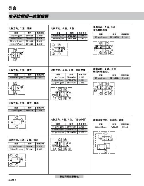
型号 PV08-31 PV70-31 PV72-31 PV76-31
手册页码 2.380.1 2.382.1 2.384.1 2.386.1
比例流量控制,常开
流量 38 lpm/10 gpm 87 lpm/23 gpm
型号 PV70-35 PV72-35
手册页码 2.432.1 2.434.1
比例流量控制,旁通,常闭
流量 22 lpm/6 gpm 30 lpm/8 gpm 64 lpm/17 gpm 151 lpm/40 gpm
型号 PV08-30 PV70-30 PV72-30 PV76-30A
手册页码 2.370.1 2.372.1 2.374.1 2.376.1
比例流量控制,旁通,常闭
流量
型号
手册页码
190 lpm/50 gpm PV42-M30 2.378.1
缩写符号:
比例压力控制,先导溢流,电流增 大压力增大
流量 95 lpm/25 gpm 189 lpm/50 gpm
型号 TS10-26 TS12-26
手册页码 2.852.1 2.854.1
0.002.3
截止阀 (典型)
电子比例阀—选型指导
比例压力控制,先导溢流,电流增 大压力减小
流量 19 lpm/5 gpm 76 lpm/20 gpm 189 lpm/50 gpm
—
推荐的电子控制器
仅指 PCB 板
铁盒式
零件编号 手册页码 零件编号 手册页码
4000046 4000141 4000143 4000144
3.426.1 3.427.1 3.428.1 3.429.1
4000049 4000124 4000130 4000133
TAKEX光纤传感器说明书
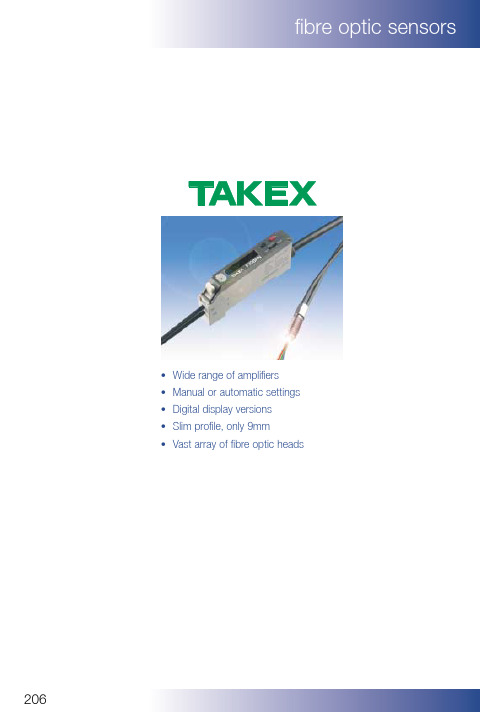
206•Wide range of amplifiers •Manual or automatic settings •Digital display versions •Slim profile, only 9mm •Vast array of fibre optic headsF70 series touch to teach amplifier208 F71 series manual amplifier210 F2 series manual amplifier212 Fibre accessories213 Throughbeam fibres214 Diffuse fibres215207208•LCD display•Multifunction timer•Touch to teach setting•Remote setting•Self diagnostics•Red, blue green & white light•Light on/dark on•NPN/PNP•Alarm output•Ultra slim design•Twin output version F70 SERIES FIBRE OPTIC AMPLIFIER ELECTRICAL SPECIFICATIONSodel F70R-NPN F70G-NPN F70B-NPN F70W-NPN F70TW-NPN F70R-PNP F70G-PNP F70B-PNP F70W-PNP F70TW-PNP Detection Through-beam/Reflection (By fibre unit)Range Depending on fibre unitPower Supply12–24VDC ±10% Ripple 10% or lessCurrent consumption NPN type : 39mA or less PNP type : 50mA or lessOpen collectorOutputOutput NPN/PNP 100mA (30VDC)NPN/PNP (30VDC) CH1:100mA, CH2:50mAmode Open collector None StabilityNPN/PNP 50mA (30VDC)None OutputOperation mode Light-On/Dark-On selectableTimer On delay/Off delay/On-Off delay/non-delay selectableTimer time: 10/20/40/60/80/100/120ms. selectable.External teachingNon voltage (contact/non-contact)inputResponse time Transmission frequency Channel 1: 500µs. or lessChannel 2: 600µs. or lessLight source Red LED Green LED Blue LED White LED White LED (wave length)(660nm)(565nm)(470nm)(450 ~ 750nm)(450 ~ 750nm) Indicator Operation indicator : Orange LED,Stability indicator : Green LEDDisplay LCD with back lightSwitch Setting button : 2 Operation changeover switch:RUN/SELECT/MODETeaching system Full auto teaching/Auto teachingTeaching input Setting button/External inputFeatures• Sensor feature: Auto sensing/Teaching/Locking• Accessory feature:S-Manual setting for sensitivity/ON-operation levelH-Manual setting for hysteresisV-Light variation indication mode/Absolute valueindication mode• Interference protection built-in• Self-diagnostic built-in• Short circuit protection built-inMaterial PolycarbonateWiring Cable (outer dimension:dia.4.8) 0.2sq. 5 core 2m lengthWeight Approx.80g (including mounting bracket)Ambient illumination Incandescent lamp: 10,000lx or less Sun light: 20,000lx or lessAmbient temperature–25~+55ºC (storage:–40~+70ºC)in case of multiple installations 1-4pcs: –25~ +55ºC5pcs or more:–25~+45ºCDIMENSIONSCONNECTION DIAGRAM1Stability indicator 2Operation indicator4Operation mode indicator 5Electronic volume position indicator 6Incoming light level indicator 7Features indicator8Transmission frequency channel indicator9Operation changeover switchLCD display descriptionNote: If the load is inductive (relay coil, solenoid) or if there are inductive loadsin parallel with the load, connect a diode (N4002) in parallel with the coil.NPN OutputF70F70TPNP OutputDC12~24V CH1 OUTPUT CH2 OUTPUT 0VDC12~24VCH1 OUTPUT CH2 OUTPUT 0V NPN OUTPUT210•Ultra slim design•High gain•Anti mutual interference to 8 sensors•Fast 30 µsec response time available•Light on/dark on selectable•Stability output•Available in red, green, blue & white LEDF71 SERIES FIBRE OPTIC AMPLIFIER211Turbo function•When the turbo mode changeover switch is set to “8”, the turbo function willoperate. When the turbo function operates, the response time will be 500µsec, but the detection distance will be increased by approx. 30% from when the turbo function is OFF (“4”).Anti Mutual Interference•This product has an Anti Mutual Interference function that uses optical transfer. For the optical transfer there is a window on the side of the unit which is the optical path. There are transmitter and receiver windows. Therefore, install the units on a DIN rail and match the transfer windows of the amplifier units next to each other, as shown in the drawing, in order to ensure the function of the Anti Mutual Interference.Interference selectable switch4 units do not interfere (Response time : 250µs)8 units do not interfere (Response time : 500µs)Cautions:If the amplifier units are mounted next to each other and they are notaligned, or if the gaps between the amplifier units are too large, or if the light path between the transfer window is blocked, the optical transfer will become impossible and malfunction will occur.SensitivityadjustmentCONNECTION DIAGRAMDIMENSIONS•Loaded short circuit or overload shuts off the output transistor.•Turn the power back on after checking the loaded condition.NPN outputPNP output8484ORDERING GUIDEType No.DescriptionOutput F2R-PNP-J Amplifier (Connector type)PNP F2R-NPN-J Amplifier (Connector type)NPN F2R-PNPAmplifier (Flying lead)PNPType No.DescriptionOutput F2R-NPNAmplifier (Flying lead)NPN503000E02M050Connector - straight - 5m long 503001E02M050Connector - 90°- 5m longLight on – Dark onSensitivity adjustmentTECHNICAL DATA•Unique compact design •Response time 0.5ms•0.03mm minimum object size detection •IP65 sealed•Sensitivity adjustment (Dual LED setting)•Light On/Dark On selectable •NPN or PNP types available •Mounting by screws or DIN rail •Wide selection of available fibres •Choice of connector or flying lead typesF2 SERIES FIBRE OPTIC AMPLIFIER212fibre optic sensors2131212aHead Connector Brass (Nickel Plated)Spiral Tube SUS304End CapBrass (Nickel Plated)bc1000mmdeFIBRE PROTECTIONFIBRE ACCESSORIESFA3SP10FA4SP10FA6SP10Dimensionsa 6mm 8.5mmb 4.8mm 7mmc 6mm 8.5mmd 3mm5mm e M3 x 0.5M4 x 0.7M6 x 0.75Applicable FT8BC FT5BC, FTS5BC FR7BCfibres FTS88BCFTSV5BC, FT7BCBending 30mmradiusACCESSORYPART TO BE EFFECTIVE M INI M U M OBJECTDIMENSION (mm)NUMBER USED WITHRANGE RESOLUTIONFocusing head*FX210J10~11mm0.3~0.5mm øFA200FX8401BC FX210J7~16mm0.5 ~1.7mm øFA240FX8401BCFX210J18~25mm0.4 ~0.7mm øFA250FX8401BCFiber cable(8~1)1596ø6Lens Body (Aluminum, Black)ø4Fiber head Screw M2.6X3ø10Lens45(15)7Body(Aluminum, Black)THROUGHBEAM FIBRESFT5BCFT7BCFT8EBCFTSV82BCFTL716BCFU712BC2,000 (30R)153Ø 2.2M4 P=0.7M2.6 P=0.452,000 (30R)20101035Ø 2.22-M3 P=0.551VIEW A 4A Ø0.265 x 162,000 (30R)205Ø412Ø 2.2M5 P=0.82,000 (30R)252,000 (30R)153ø2.2ø2.2M4.P=0.7 (SUS303)M2.6 P=0.45214215FRS83BCFRSV83BCFRL732BCFX210FX8401BCø2.21732,000(30R)M6. P=0.75(SUS303)2,000 (30R)2510101945112-M3 P=0.5AVIEW AØ0.265 x 16 x 2(11.1)2,000 (15R)15ø1.25M4.P=0.7(SUS303)3.1~0.50.8216•Wide range of photoelectric sensors •Diffuse, retro reflective & throughbeam versions •Background suppression, colour & clear bottle detection •Wide range of voltage options •Solid state or relay outputs217UM series 218Mini G series219Mini DL series background suppression and colour mark 220Midi G series221CX M18 barrel DC series 222CX M18 barrel AC series 223NE DC series 224NE AC/DC series 225NA series226NAL series 227J series228DAS series zone sensor 229DLS seriesbackground suppression 230-231DLAS series analogue sensor 232NESMT1 clear bottle detector 233CS-D3 colour sensor 234High power sensors235-237Throughbeam types UMT15DT UMT15DTV UMT50DT UMT50DTV UMT50DSDiffuse typesUMR3T UMR3TVUMR5TUMR5TVConvergent typesUMZ3SVPlease specify NPN or PNP output when ordering.ORDERING GUIDE•Ultra Miniature size. Three types i (19.5x18x3.5mm)ii (20x9x7mm)iii (18x12.5x3.5mm)•Throughbeam, diffuse or convergent beam•Sensitivity adjustment option •Response time 0.5ms •IP64 sealed•80mA, open collector output •Short circuit protectedUM SERIES218219•Sub miniature 10.3 x 15 x 25.4mm •Housing sealed to IP67•Light On/Dark On selectable•Long range (up to 7m) throughbeam•Brackets, reflector & pinhole masks supplied (where applicable)•Response time 0.35ms•Stability output (only NPN types)Type No.DescriptionLight Source RangeGT1Throughbeam - Basic Infrared 1m GT1S Throughbeam - Side On Infrared 1m GT3Throughbeam - Basic Infrared 3m GT3RS Throughbeam - Side On Red 5m GT7S Throughbeam - Side On Infrared 7m GSM2RS Retro reflective - Side On Red 2m GS5Diffuse - BasicInfrared5cmK71Reflector (included)K7ReflectorType No.Description Light Source RangeGS5S Diffuse - Side On Infrared 5cm GS20RS Diffuse - Side On Red 20cm GS20Diffuse - Basic Infrared 30cm GS20S Diffuse - Side On Infrared 30cm GSZ3S Convergent beam - Side On Infrared 40mm GSZ3RSConvergent beam - Side On Red30mmPlease specify NPN or PNP output when ordering.* Using included K71 reflector. Range can be extended to 4m by using K7 reflector.220•Close range background suppression•Detects objects of any colour, size, or shape, but ignores background•Light-on, Dark on Switchable •Response time 0.35ms •IP67 sealed•NPN or PNP types availableType No.DL-S5-NPN/PNPDL-S5R-NPN/PNPDL-S10R-NPN/PNP DL-S20-NPN/PNP GR100R-NPN/PNPDetection method Convergent beamColour mark Range50mm*50mm*100mm**200mm**100mmPower supply 12-24VDC +/- 10% Max ripple 10%Current cons 27mA max 30mA max 25mA maxOperating mode Light on/Dark on selectable by switch Output rating NPN/PNP open collector 100mA at 30VDC***Alarm rating NPN/PNP open collector 50mA at 30VDC***Protection short circuit protection (output only)Response time 0.35msecLight source Infa red LED (880nm)Red LED (700nm)Red LED (700nm)Infra red LED (880nm)Red LED (700nm)LED indicationOutput red LED : Stability green LEDSensitivity adjustment By potentiometerHousing Polycarbonate sealed to IP67Cable4 x 0.15mm, 2m long, Ø 3mm 4 x 0.2mm, 2m long, Ø 4mmAmbient light 5000 lux max 3000 lux max Operating temp.-25 to +55 °C -10 to +55 °CHumidityWithstands 85% RH* 50 x 50mm white paper with sensitivity set to max. ** 100 x 100mm white paper with sensitivity set to max.*** PNP types do not have stability output.TECHNICAL SPECIFICATIONDLS5-NPN Convergent beam, infra red light source, 50mm range NPN DLS5-PNP Convergent beam, infra red light source, 50mm range PNP DLS5R-NPN Convergent beam, red light source, 50mm range NPN DLS5R-PNP Convergent beam, red light source, 50mm range PNP DLS10R-NPN Convergent beam, red light source, 100mm range NPN DLS10R-PNP Convergent beam, red light source, 100mm rangePNP DLS20-NPN Convergent beam, infra red light source, 200mm range NPN DLS20-PNP Convergent beam, infra red light source, 200mm range PNP GR100R-NPN Colour mark sensor, red light source, 100mm range NPN GR100R-PNPColour mark sensor, red light source, 100mm rangePNP221•Miniature 11.5 x 20 x 36mm •Polarised lens•Housing sealed to IP67•Light On/Dark On switchable •Response time 0.5ms•Brackets and reflector included •Cabled or Connector typesType Number DescriptionOutput Range GT5RS-NPN-N Throughbeam side on NPN 7m GT5RS-PNP-N Throughbeam side on PNP 7m GT5R-NPN-N Throughbeam NPN 7m GT5R-PNP-N ThroughbeamPNP 7m GMR2RS-NPN-N Retro-reflective side on NPN 1.5m GMR2RS-PNP-N Retro-reflective side on PNP 1.5m GMR2RS-NF Retro-reflective side on NPN 4m GMR2R-NPN-NRetro-reflectiveNPN 1.5mType NumberDescription Output Range GMR2R-PNP-N Retro-reflective PNP 1.5m GSR05RS-NPN-N Diffused side on NPN 0.5m GSR05RS-PNP-N Diffused side on PNP 0.5m GSR05R-NPN-N Diffused NPN 0.5m GSR05R-PNP-N Diffused PNP 0.5mK-71Reflector (included)K-7Reflector•Light source: Red LED (700nm)•Power supply: 12-24VDC ±10% max ripple 10%•Output:100mA at 30VDC max•Max. ambient light: 5,000 lux •Indication: Throughbeam;Transmitter: power on - red LED.Receiver: detection - red LEDstability - green LEDDiffuse & Retro-reflective;Detection-red LED, stability - green LED•Sensitivity adjustment:Potentiometer•Temp. range: -25°c to +55°c•Protection: IP67•Housing: Polycarbonate•Connection: Flying lead 3x0.5mm 2, 2m long (Transmitter 2x0.5mm 2,2m long) or M8 4 Pin Connector * Using K-71 reflector (0.03-2.5m with K-7 reflector) ** Using K-71 reflector (0.03-6m using K-7 reflector) *** Using 100x100mm white paper.WIRING*For Connector types add -J to the part number. e.g. GSR05RS-NPN-NJ222Type No.DescriptionOutput RangeCXM2RD-NPN Retro-reflective 2m cable NPN 2m CXM2RD-PNP Retro-reflective 2m cablePNP 2m CXM2RD-NPN-J Retro-reflective M8 Connector NPN 2m CXM2RD-PNP-J Retro-reflective M8 Connector PNP 2m CXR01-NPN Diffuse 2m cable NPN 100mm CXR01-PNP Diffuse 2m cablePNP 100mm CXR01-NPN-J Diffuse M8 Connector NPN 100mm CXR01-NPN-JDiffuse M8 ConnectorNPN100mmType No.Description Output Range CXR01-PNP-J Diffuse M8 Connector PNP 100mm CXR03V-NPN Diffuse 2m cable adjustable NPN 300mm CXR03V-PNP Diffuse 2m cable adjustable PNP 300mm CXR03V-NPN-J Diffuse M8 Connector adjustable NPN 300mm CXR03V-PNP-J Diffuse M8 Connector adjustable PNP 300mm K7Reflector (Included with Retro-reflective sensor)* With included K7 reflector. ** Using 50x50mm white paper, range will vary depending on target size and surface.•Short body •Flat lens•Easy mounting•Housing sealed to IP66•LED indication•Plug in types available (J- suffix)223* With included K-7 reflector. ** Using 50x50mm white paper, range will vary depending on target size and surface.Type No.Description Connection RangeCXM1RDTW Retro-reflective polarised Cable 1m CXM1RDTW-J Retro-reflective polarised Connector 1m CXM2DTWRetro-reflective Cable2mType No.Description Connection RangeCXM2DTW-J Retro-reflective Connector 2m CXS01TW Diffuse Cable 100mm CXS01TW-J Diffuse Connector 100mmK-7ReflectorORDERING GUIDE•2 - wire 90 - 260VAC•Flat polarised lens (R - version)•LED indication •Easy mounting•Housing sealed to IP66•Plug in type available (J - suffix)224ELECTRICAL CONNECTIONDIMENSIONS •High power photosensor •Compact Housing •30m through beam•5m polarised retro reflective •1m diffuse•2 outputs NPN and PNP•External transmit inhibit input (throughbeam only)NE DC SERIES•High Power Photosensor •Compact Housing•Multivoltage 24 - 240 VAC/DC •N/O N/C Relay Outputs •Polarised Retro Reflective•30 Metre Throughbeam RangeNE AC/DC SERIESDIMENSIONS ELECTRICAL CONNECTIONreduce minimum object resolutionPinhole Model NE-P3NE-P5NE-P5X1NE-T10R (D)1m 3m 0.7m NE-T30 (D )3m7m 2mReflector Range K-70.03~5m K-710.03~2m K-20.1 ~3m S-510G0.1 ~3mDetection distances when the pinhole masks are attached onto both the transmitter and the receiver.226Type Number Description RangeNAR10Diffused1m NAR10F Diffused + timer 1m NAM7R Retro-reflective7m NAM7RFRetro-reflective + timer7mType Number Description Range NAT20R Throughbeam20m NAT20RF Throughbeam + timer 20mBG11553X Connector adaptor M12*AP35Pinhole mask*For Connector type add -J to the part number. e.g. NARI0-J. Refer to page 194 for connection details.ORDERING GUIDE•Compact Housing•Retro reflective uses polarised light•Multivoltage 24-240Vac/dc •Large screw terminals•Optional connector adaptor •SPST Output Relay•Multifunction timer (F-versions)•Housing sealed to IP66227•Long range retro reflective •Polarised light•Multivoltage version•Solid state or relay output •Large screw terminals •Housing to IP67228•Slim bodied side ways looking •Quick change sensor head•Multi voltage 24-240VAC/DC (Relay models)•Polarised lenses to eliminate false triggering •Housing sealed to IP66•Multifunction timer (0.1-10sec) F - versionsJ SERIES INDUSTRIAL* K7 Reflector used **F - versions onlyType Number Description Power suppy Output Range JT10R Throughbeam sensor 24 - 240V AC/DC Relay 10m JRM3R Retro-reflective sensor 24 - 240V AC/DC Relay 3m JR07Diffuse sensor 24 - 240V AC/DC Relay 500mm JNT10R Throughbeam sensor 12 - 24V DC ±10%PNP/NPN 10m JNRM3R Reto-reflective sensor 12 - 24V DC ±10%PNP/NPN 3m JNR05Diffuse sensor 12 - 24V DC ±10%PNP/NPN 500mm JT10RF Throughbeam with timer 24 - 240 AC/DC Relay 10m JRM3RF Retro-reflective with timer 24 - 240V AC/DC Relay 3m JR07F Diffuse with timer 24 - 240V AC/DC Relay500mmK7Reflector 40x60mmR75XDM Polarised reflective tape 75x750mmJB5Brackets (optional accessories) for wall mounting JP37Pinhole masks for throughbeam models BG11553XConnector adaptor M12 see page 194229DAS40R-NPN DAS100RTC DAS40R-PNP DAS100RP DAS40R-J Refer to page 194 for connectors DAS200TC DAS70-NPN DAS200P DAS70-PNP BG11553XConnector adapter M12*DAS70-JRefer to page 194 for connectors*For DAS100 & 200 add -J to part number for connector type e.g. DAS100RTC-J, Refer to page 194 for connectorsDAS SERIES ZONE SENSOR•Electronic foreground and background suppression •Anti cross talk•Wide voltage range •Detection up to 2m •Housing to IP67ORDERING GUIDE230DLS SERIES INDUSTRIAL•Background suppression by optical focusing•Detects objects of any colour, material or shape against similar background •Powerful beam for good operation even in dirty object, dirty lens conditions •Relay or solid state output options•Adjustable range: 0.2m to 1m - DL-S100, 0.2m to 2m - DL-S200, 150mm to 600mm - DL-7050•IP66 SealedORDERING GUIDERelay Output Types DL - S100P DL - S200P DL-7050PNP/NPN Output Types DL - S100TC DL - S200TCType Number DescriptionRange Output DLS100P Convergent Reflection 0.2 - 1M Relay DLS200P -0.2 - 2MRelay DL7050-150 - 600mmRelayType Number Description Range Output DLS100TC Convergent Reflection 0.2 - 1M PNP/NPN DLS200TC -0.2 - 2MPNP/NPNBG11553XConnector adaptor M12*NOTE: Do not use a mirror or reflector as a background432112 -24 VDCPNP NPN +––+*For Connector types add -J to the part number. e.g. DLS100P-J. Refer to page 194 for connection details.231•Background suppression by optical focusing•Detects objects of any colour material or shape against similar background •Detection to 2 metres•5 turn distance adjustment •2 outputs NPN and PNPDLS100R/DLS202COLOUR PAPER CHARACTERISTICSDIMENSIONSCONNECTION DIAGRAM Loaded short circuit or overload shuts off the output transistor.Turn the power back on after checking the loaded condition.232•Supply 24V DC•Proportional DC volt output•2 settable switchpoints available •IP66, (IP40 on DLAS 150)DLAS ANALOGUE OUTPUTORDERING GUIDEType No DescriptionRange DLAS150Analogue O/P 1-10V 50-150mm DLAS300Analogue O/P 1-10V 150-300mmDLAS1000Analogue O/P 3-9V0.2-1m233•Transparent bottle detection •Retro reflective mode •Auto/remote setting •12 - 24V operation •Protection to IP66•1 ms response time (max).NESMT1ORDERING GUIDEDIMENSIONSType NoDescriptionOutput NESMT1 - NPN Retro Reflective Light On NPN NESMT1 - PNP Retro Reflective Light On PNP NESMT1D - NPN Retro Reflective Dark On NPN NESMT1D - PNPRetro Reflective Dark OnPNPReflectorReflector Mounting234•Auto Set Colour Sensor•Three Programmable Settings •Choice of Fibres•Colour and Brightness Discrimination •Fast Response TimesCS-D3 SERIES COLOUR SENSORBASIC OPERATIONDIMENSIONS•When an initial setting (teaching) for a basic colour is carried out, the Max/Min tolerance value (allowance)toward the standard colour is set according toTolerance volume position. The sensor recognises it as a coincidence that the incoming light level comes in this range (Max-Min).•The sensor calculates the basic operation to issue an output according to the programmed mode for 3colours (red, green and blue).Stable detection is obtained when the fibre unit is installed at the standard distance, on the other hand, the installation is allowed even at the following distance.Installation distance referenceCS-DF30Standard distance 33mm Allowable distance 28 to 38mm CS-DF10Standard distance 13mm Allowable distance 10 to 16mmTightening torque for fixing CS-DF10/CS-DF30 should be 0.6Nm or less.。
变频器的外部运行操作
任务2 变频器的外部运行操作任务目的:1.掌握MM440变频器基本参数的输入方法。
2.掌握MM440变频器输入端子的操作控制方式。
3.熟练掌握MM440变频器的运行操作过程。
任务引入:变频器在实际使用中,电动机经常要根据各类机械的某种状态而进行正转、反转、点动等运行,变频器的给定频率信号、电动机的起动信号等都是通过变频器控制端子给出,即变频器的外部运行操作,大大提高了生产过程的自动化程度。
下面就来学习变频器的外部运行操作相关知识。
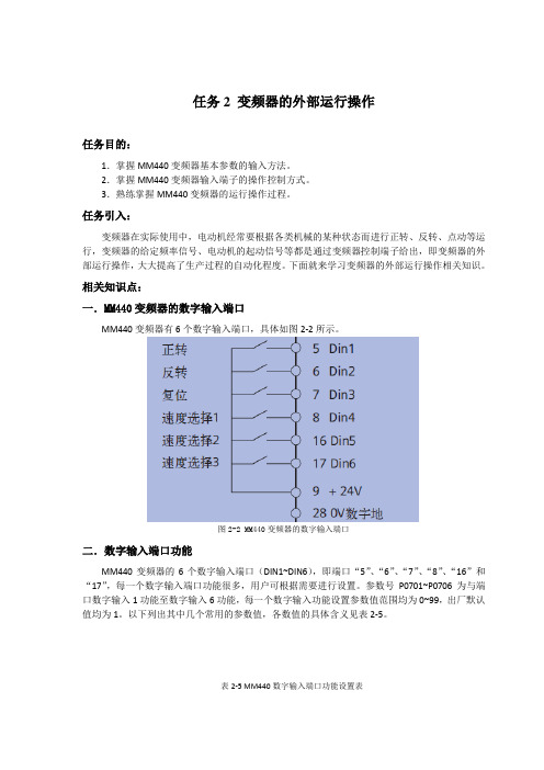
相关知识点:一.MM440变频器的数字输入端口MM440变频器有6个数字输入端口,具体如图2-2所示。
图2-2 MM440变频器的数字输入端口二.数字输入端口功能MM440变频器的6个数字输入端口(DIN1~DIN6),即端口“5”、“6”、“7”、“8”、“16”和“17”,每一个数字输入端口功能很多,用户可根据需要进行设置。
参数号P0701~P0706为与端口数字输入1功能至数字输入6功能,每一个数字输入功能设置参数值范围均为0~99,出厂默认值均为1。
以下列出其中几个常用的参数值,各数值的具体含义见表2-5。
表2-5 MM440数字输入端口功能设置表任务训练:一、训练内容用自锁按钮SB1和SB2,外部线路控制MM440变频器的运行,实现电动机正转和反转控制。
其中端口“5”(DIN1)设为正转控制,端口“6”(DIN1)设为反转控制。
对应的功能分别由P0701和P0702的参数值设置。
二、训练工具、材料和设备西门子MM440变频器一台、三相异步电动机一台、断路器一个、熔断器三个、自锁按钮二个、导线若干、通用电工工具一套等。
三、操作方法和步骤1.按要求接线变频器外部运行操作接线图如图2-2所示。
~380v图2-2 外部运行操作接线图2.参数设置接通断路器QS,在变频器在通电的情况下,完成相关参数设置,具体设置见表2-6。
表2-6 变频器参数设置3.变频器运行操作(1)正向运行:当按下带锁按钮SB1时,变频器数字端口“5”为ON,电动机按P1120所设置的5S斜坡上升时间正向启动运行,经5S后稳定运行在560r/min的转速上,此转速与P1040所设置的20Hz对应。
SSPC-SP10

Joint Surface Preparation Standard SSPC-SP NO. 10/NACE NO. 2 Near-White Blast CleaningThis SSPC: The Society for Protective Coatings and NACE International standard represents a consensus of those individual members who have reviewed this docu-ment, its scope and provisions. Its acceptance does not in any respect preclude anyone, having adopted the standard or not, from manufacturing, marketing, purchasing, or using products, processes, or procedures not in conformance with this standard. Nothing contained in this standard is to be construed as granting any right, by implication or otherwise, to manufacture, sell, or use in connection with any method, apparatus, or product covered by Letters Patent, or as indemnifying or protecting anyone against liability for in-fringement of Letters Patent. This standard represents minimum requirements and should in no way be interpreted as a restriction on the use of better procedures or materials. Neither is this standard intended to apply in all cases relating to the subject. Unpredictable circumstances may negate the usefulness of this standard in specific instances. SSPC and NACE assume no responsibility for the interpre-tation or use of this standard by other parties and accept responsibility for only those official interpretations issued by SSPC or NACE in accordance with their respective govern-ing procedures and policies, which preclude the issuance of interpretations by individual volunteers.Users of this standard are responsible for reviewing appropriate health, safety, and regulatory documents and for determining their applicability in relation to this standard prior to its use. This SSPC/NACE standard may not neces-sarily address all potential health and safety problems or environmental hazards associated with the use of materials, equipment and/or operations detailed or referred to within this standard. Users of this standard are also responsible for establishing appropriate health, safety, and environmental protection practices, in consultation with appropriate regu-latory authorities, if necessary, to achieve compliance with any existing applicable regulatory requirements prior to the use of this standard.CAUTIONARY NOTICE: SSPC/NACE standards are subject to periodic review and may be revised or withdrawn at any time without prior notice. SSPC and NACE require that action be taken to reaffirm, revise, or withdraw this standard no later than five years from the date of initial publication. The user is cautioned to obtain the latest edition. Purchasers may receive current information on all standards and other publications by contacting the organi-zations at the addresses below:©NACE InternationalP.O. Box 218340Houston, TX 77218-8340(telephone +1 281/228-6200)© SSPC: The Society for Protective Coatings40 24th Street, Sixth FloorPittsburgh, PA 15222(telephone +1 412/281-2331)ForewordThis joint standard covers the use of blast cleaning abrasives to achieve a defined degree of cleaning of steel surfaces prior to the application of a protective coating or lining system. This standard is intended for use by coating or lining specifiers, applicators, inspectors, or others whose responsibility it may be to define a standard degree of surface cleanliness.The focus of this standard is near-white metal blast cleaning. White metal blast cleaning, commercial blast cleaning, industrial blast cleaning and brush-off blast clean-ing are addressed in separate standards.Near-white blast cleaning provides a greater degree of cleaning than commercial blast cleaning (SSPC-SP 6/NACE No. 3), but less than white metal blast cleaning (SSPC-SP 5/ NACE No. 1).Near-white blast cleaning is used when the objective is to remove all rust, coating, and mill scale, but when the extra effort required to remove all stains of these materials is determined to be unwarranted. Staining shall be limited to no more than 5 percent of each unit area of surface.Near-white blast cleaning allows staining on only 5 percent of each unit area of surface, while commercial blast cleaning allows staining on 33 percent of each unit area of surface. White metal blast cleaning does not permit any staining to remain on the surface.This joint standard was prepared by the SSPC/NACE Task Group A on Surface Preparation by Abrasive Blast Cleaning. This joint Task Group includes members of both the SSPC Surface Preparation Committee and the NACE Unit Committee T-6G on Surface Preparation.1. General1.1 This joint standard covers the requirements for near-white blast cleaning of unpainted or painted steel surfaces by the use of abrasives. These requirements include the end condition of the surface and materials and procedures necessary to achieve and verify the end condi-tion.1.2This joint standard allows random staining to remain on no more than 5 percent of each unit area of surface as defined in Section2.6.1.3The mandatory requirements are described in Sections 1 to 9 as follows:Section 1GeneralSection 2DefinitionSection 3ReferencesSection 4Procedures Before Blast CleaningSection 5Blast Cleaning Methods and OperationSection 6Blast Cleaning AbrasivesSection 7Procedures Following Blast Cleaning andImmediately Prior to CoatingSection 8InspectionSection 9Safety and Environmental Requirements NOTE: Section 10, “Comments” and Appendix A, “Explana-tory Notes” are not mandatory requirements of this stan-dard.2. Definition2.1 A near-white metal blast cleaned surface, when viewed without magnification, shall be free of all visible oil, grease, dust, dirt, mill scale, rust, coating, oxides, corrosion products, and other foreign matter, except for staining as noted in Section 2.2.2.2 Random staining shall be limited to no more than 5 percent of each unit area of surface as defined in Section 2.6, and may consist of light shadows, slight streaks, or minor discolorations caused by stains of rust, stains of mill scale, or stains of previously applied coating.2.3Acceptable variations in appearance that do not affect surface cleanliness as defined in Section 2.1 include variations caused by type of steel, original surface condi-tion, thickness of the steel, weld metal, mill or fabrication marks, heat treating, heat affected zones, blasting abra-sives, and differences in the blast pattern.2.4 When a coating is specified, the surface shall be rough-ened to a degree suitable for the specified coating system.2.5 Immediately prior to coating application, the entire surface shall comply with the degree of cleaning specified herein.2.6 Unit area for determinations shall be approximately 5776 mm2 (9 in2) (i.e., a square 76 mm x 76 mm [3 in x 3 in]).2.7 SSPC-VIS 1-89, photographs A SP-10, B SP-10, C SP-10 or D SP-10 may be specified to supplement the written definition. In any dispute, the written standards shall take precedence over visual standards and comparators. Additional information on visual standards and comparators is available in Section A.4 of Appendix A.3. References3.1The documents referenced in this standard are listed in Section 3.4.3.2The latest issue, revision, or amendment of the referenced standards in effect on the date of invitation to bid shall govern unless otherwise specified.3.3 If there is a conflict between the requirements of any of the cited reference standards and this standard, the requirements of this standard shall prevail.3.4 SSPC: THE SOCIETY FOR PROTECTIVE COAT-INGS STANDARDS:AB 1Mineral and Slag AbrasivesAB 2Cleanliness of Recycled Ferrous MetallicAbrasivesAB 3Newly Manufactured or Re-ManufacturedSteel AbrasivePA Guide 3A Guide to Safety in Paint ApplicationSP 1Solvent CleaningVIS 1Visual Standard for Abrasive Blast CleanedSteel4. Procedures Before Blast Cleaning4.1 Before blast cleaning, visible deposits of oil, grease, or other contaminants shall be removed in accordance with SSPC-SP 1 or other agreed upon methods.4.2 Before blast cleaning, surface imperfections such as sharp fins, sharp edges, weld spatter, or burning slag should be removed from the surface to the extent required by the procurement documents (project specification). Ad-ditional information on surface imperfections is available in Section A.5 of Appendix A.4.3 If a visual standard or comparator is specified to supplement the written standard, the condition of the steel prior to blast cleaning should be determined before the blasting commences. Additional information on visual stan-dards and comparators is available in Section A.4 of Appen-dix A.5. Blast Cleaning Methods and Operation5.1 Clean, dry compressed air shall be used for nozzle blasting. Moisture separators, oil separators, traps, or other equipment may be necessary to achieve this requirement.5.2 Any of the following methods of surface preparation may be used to achieve a near-white blast cleaned surface:5.2.1 Dry abrasive blasting using compressed air, blast nozzles, and abrasive.5.2.2 Dry abrasive blasting using a closed-cycle, recir-culating abrasive system with compressed air, blast nozzle, and abrasive, with or without vacuum for dust and abrasive recovery.5.2.3Dry abrasive blasting using a closed cycle, recirculating abrasive system with centrifugal wheels and abrasive.5.3 Other methods of surface preparation (such as wet abrasive blasting) may be used to achieve a near-white blast cleaned surface by mutual agreement between those parties responsible for establishing the requirements and those responsible for performing the work. NOTE: Informa-tion on the use of inhibitors to prevent the formation of rust immediately after wet blast cleaning is contained in Section A.9 of Appendix A.6. Blast Cleaning Abrasives6.1 The selection of abrasive size and type shall be based on the type, grade, and surface condition of the steel to be cleaned, type of blast cleaning system employed, the finished surface to be produced (cleanliness and rough-ness), and whether the abrasive will be recycled.6.2 The cleanliness and size of recycled abrasives shall be maintained to ensure compliance with this specification.6.3 The blast cleaning abrasive shall be dry and free of oil, grease, and other contaminants as determined by the test methods found in SSPC-AB 1, AB 2 and AB 3.6.4 Any limitations on the use of specific abrasives, the quantity of contaminants, or the degree of allowable embed-ment shall be included in the procurement documents (project specification) covering the work, because abrasive embed-ment and abrasives containing contaminants may not be acceptable for some service requirements. NOTE: Addi-tional information on abrasive selection is given in Section A.2 of Appendix A.7. Procedures Following Blast Cleaning and Immediately Prior to Coating7.1 Visible deposits of oil, grease, or other contami-nants shall be removed according to SSPC-SP 1 or another method agreed upon by those parties responsible for estab-lishing the requirements and those responsible for perform-ing the work.7.2Dust and loose residues shall be removed from prepared surfaces by brushing, blowing off with clean, dry air, vacuum cleaning, or other methods agreed upon by those responsible for establishing the requirements and those responsible for performing the work. NOTE: The presence of toxic metals in the abrasives or paint being removed may place restrictions on the methods of cleaning permitted. Comply with all applicable regulations. Moisture separators, oil separators, traps, or other equipment may be necessary to achieve clean, dry air.7.3After blast cleaning, surface imperfections that remain (e.g., sharp fins, sharp edges, weld spatter, burning slag, scabs, slivers, etc.) shall be removed to the extent required in the procurement documents (project specifica-tion). Any damage to the surface profile resulting from the removal of surface imperfections shall be corrected to meet the requirements of Section 2.4. NOTE: Additional infor-mation on surface imperfections is contained in Section A.5 of Appendix A.7.4 Any visible rust that forms on the surface of the steel after blast cleaning shall be removed by recleaning the rusted areas to meet the requirements of this standard before coating. NOTE: Information on rust-back (re-rust-ing) and surface condensation is contained in Sections A.6, A.7 and A.8 of Appendix A.8. Inspection8.1 Work and materials supplied under this standard are subject to inspection by a representative of those re-sponsible for establishing the requirements. Materials and work areas shall be accessible to the inspector. The proce-dures and times of inspection shall be as agreed upon by those responsible for establishing the requirements and those responsible for performing the work.8.2 Conditions not complying with this standard shall be corrected. In the case of a dispute, an arbitration or settle-ment procedure established in the procurement documents (project specification) shall be followed. If no arbitration or settlement procedure is established, then a procedure mu-tually agreeable to purchaser and supplier shall be used.8.3 The procurement documents (project specification) should establish the responsibility for inspection and for any required affidavit certifying compliance with the specifica-tion.9. Safety and Environmental Requirements9.1Because abrasive blast cleaning is a hazardous operation, all work shall be conducted in compliance with applicable occupational and environmental health and safety rules and regulations. NOTE: SSPC-PA Guide 3, “A Guide to Safety in Paint Application,” addresses safety concerns for coating work.10. Comments10.1Additional information and data relative to this standard are contained in Appendix A. Detailed information and data are presented in a separate document, SSPC-SP COM, “Surface Preparation Commentary.” The recommen-dations contained in Appendix A and SSPC-SP COM are believed to represent good practice, but are not to be considered requirements of the standard. The sections of SSPC-SP COM that discuss subjects related to near-white blast cleaning are listed below.Subject Commentary SectionAbrasive Selection (6)Film Thickness (10)Wet Abrasive Blast Cleaning...........8.2Maintenance Repainting..................4.2Rust-back (Re-rusting).....................8.3Surface Profile..................................6.2Visual Standards (11)Weld Spatter..................................4.4.1Appendix A. Explanatory NotesA.1 FUNCTION: Near-white blast cleaning (SSPC-SP 10/NACE No. 2) provides a greater degree of cleaning than commercial blast cleaning (SSPC-SP 6/NACE No. 3) but less than white metal blast cleaning (SSPC-SP 5/NACE No.1). It should be used when a high degree of blast cleaning is required. The primary functions of blast cleaning before coating are: (a) to remove material from the surface that can cause early failure of the coating system and (b) to obtain a suitable surface roughness and to enhance the adhesion of the new coating system. The hierarchy of blasting standards is as follows: white metal blast cleaning, near-white blast cleaning, commercial blast cleaning, industrial blast clean-ing, and brush-off blast cleaning.A.2 ABRASIVE SELECTION: Types of metallic and non-metallic abrasives are discussed in the Surface Prepa-ration Commentary (SSPC-SP COM). It is important to recognize that blasting abrasives may become embedded in or leave residues on the surface of the steel during prepa-ration. While normally such embedment or residues are not detrimental, care should be taken to ensure that the abra-sive is free from detrimental amounts of water-soluble, solvent-soluble, acid-soluble, or other soluble contaminants (particularly if the prepared steel is to be used in an immer-sion environment). Criteria for selecting and evaluating abrasives are given in SSPC-AB 1, “Mineral and Slag Abrasives,” SSPC-AB 2, “Cleanliness of Recycled Ferrous Metallic Abrasives,” and SSPC-AB 3, “Newly Manufactured or Re-Manufactured Steel Abrasives.”A.3 SURFACE PROFILE: Surface profile is the rough-ness of the surface which results from abrasive blast clean-ing. The profile depth (or height) is dependent upon the size, shape, type, and hardness of the abrasive, particle velocity and angle of impact, hardness of the surface, amount of recycling, and the proper maintenance of working mixtures of grit and/or shot.The allowable minimum/maximum height of profile is usually dependent upon the thickness of the coating to be applied. Large particle sized abrasives (particularly metal-lic) can produce a profile that may be too deep to be adequately covered by a single thin film coat. Accordingly, it is recommended that the use of larger abrasives be avoided in these cases. However, larger abrasives may be needed for thick film coatings or to facilitate removal of thick coatings, heavy mill scale, or rust. If control of profile (minimum/maximum) is deemed to be significant to coating performance, it should be addressed in the procurement documents (project specification). Typical profile heights achieved with commercial abrasive media are shown in Table 5 of the Surface Preparation Commentary (SSPC-SP COM). Surface profile should be measured in accordance with NACE Standard RP0287 (latest edition), “Field Mea-surement of Surface Profile of Abrasive Blast Cleaned Steel Surfaces Using Replica Tape,” or ASTM(1) D 4417 (latest edition), “Test Method for Field Measurement of Surface Profile of Blast Cleaned Steel.”A.4 VISUAL STANDARDS: SSPC-VIS 1-89 (Visual Standard for Abrasive Blast Cleaned Steel) provides color photographs for the various grades of surface preparation as a function of the initial condition of the steel. The series A-SP 10, B-SP 10, C-SP 10 and D-SP 10 photographs depict surfaces cleaned to a near-white blast grade. Other available visual standards are described in Section 11 of SSPC-SP COM.A.5 SURFACE IMPERFECTIONS: Surface imperfec-tions can cause premature failure when the service is severe. Coatings tend to pull away from sharp edges and(1) ASTM, 100 Barr Harbor Drive, West Conshohocken, PA 19428-2959.projections, leaving little or no coating to protect the under-lying steel. Other features that are difficult to properly cover and protect include crevices, weld porosities, laminations, etc. The high cost of the methods to remedy surface imperfections requires weighing the benefits of edge round-ing, weld spatter removal, etc., versus a potential coating failure.Poorly adhering contaminants, such as weld slag resi-dues, loose weld spatter, and some minor surface lamina-tions may be removed during the blast cleaning operation. Other surface defects (steel laminations, weld porosities, or deep corrosion pits) may not be evident until the surface preparation has been completed. Therefore, proper plan-ning for such surface repair work is essential because the timing of the repairs may occur before, during, or after the blast cleaning operation. Section 4.4 of SSPC-SP COM and NACE Standard RP0178 (latest edition), “Fabrication De-tails, Surface Finish Requirements, and Proper Design Considerations for Tanks and Vessels to be Lined for Im-mersion Service” contain additional information on surface imperfections.A.6 CHEMICAL CONTAMINATION: Steel contami-nated with soluble salts (e.g., chlorides and sulfates) devel-ops rust-back rapidly at intermediate and high humidities. These soluble salts can be present on the steel surface prior to blast cleaning as a result of atmospheric contamination. In addition, contaminants can be deposited on the steel surface during blast cleaning if the abrasive is contami-nated. Therefore, rust-back can be minimized by removing these salts from the steel surface,, and eliminating sources of recontamination during and after blast cleaning. Wet methods of removal are described in SSPC-SP 12/NACE No. 5. Identification of the contaminants along with their concentrations may be obtained from laboratory and field tests as described in SSPC-TU 4, “Technology Update on Field Methods for Retrieval and Analysis of Soluble Salts on Substrates.”A.7 RUST-BACK: Rust-back (re-rusting) occurs when freshly cleaned steel is exposed to moisture, contamination, or a corrosive atmosphere. The time interval between blast cleaning and rust-back will vary greatly from one environ-ment to another. Under mild ambient conditions, if chemical contamination is not present (see Section A.6), it is best to blast clean and coat a surface the same day. Severe conditions may require more expedient coating application to avoid contamination from fallout. Chemical contamina-tion should be removed prior to coating (see Section A.6).A.8 DEW POINT: Moisture condenses on any surface that is colder than the dew point of the surrounding air. It is, therefore, recommended that the temperature of the steel surface be at least 3 °C (5 °F) above the dew point during dry blast cleaning operations. It is advisable to visually inspect for moisture and periodically check the surface temperature and dew point during blast cleaning operations and to avoid the application of coating over a damp surface.A.9 WET ABRASIVE BLAST CLEANING: Steel that is wet abrasive blast cleaned may rust rapidly. Clean water should be used for rinsing. It may be necessary that inhibitors be added to the water or applied to the surface immediately after blast cleaning to temporarily prevent rust formation. The use of inhibitors or the application of coating over slight discoloration should be in accordance with the requirements of the coating manufacturer. CAUTION: Some inhibitive treatments may interfere with the performance of certain coating systems.A.10 FILM THICKNESS: It is essential that ample coating be applied after blast cleaning to adequately cover the peaks of the surface profile. The dry film thickness of the coating above the peaks of the profile should equal the thickness known to be needed for the desired protection. If the dry film thickness over the peaks is inadequate, prema-ture rust-through or failure will occur. To assure that coating thicknesses are properly measured the procedures in SSPC-PA 2 (latest edition), “Measurement of Dry Coating Thick-ness with Magnetic Gauges” should be used.A.11 MAINTENANCE AND REPAIR PAINTING: When this standard is used in maintenance painting, specific instructions should be given on the extent of surface to be blast cleaned or spot blast cleaned to this degree of clean-liness. In these cases, the cleaning shall be performed across the entire area specified. For example, if all weld seams are to be cleaned in a maintenance operation, this degree of cleaning shall be applied 100% to all weld seams. If the entire structure is to be prepared, this degree of cleaning shall be applied to 100% of the entire structure. SSPC-PA Guide 4 (latest edition), “Guide to Maintenance Repainting with Oil Base or Alkyd Painting Systems,” pro-vides a description of accepted practices for retaining old sound coating, removing unsound coating, feathering, and spot cleaning.。
Stata SP10 简介及基本操作

Stata 的主界面
三、Stata 操作
1.将数据导入Stata 打开Stata 软件后,点击Data → Data Editor 图标,即可打
开一个类似Excel的空白表格。然后,用Excel 打开文件 “实验数据.xls”,复制文件中的相关数据,并粘贴到Data Editor 中。
导入数据的另一方法是,点击菜单 “File”→“Import”,然后导入各种格式的数据。但这种 方法有时不如直接从Excel 表中粘贴数据来得方便直观。
丰富的网络资源:
严谨、简练、灵活的程序语言: Stata提供了严谨、简练而灵活的程序语句,用户可以编
写自己的命令和函数,也可以制作自己的对话框和窗口菜 单。
Variable Obs gov 32 gcons 32 gdp 32
Mean 14454.13 11441.76 80670.91
Std. Dev. 19217.2 12730.41 94125.31
Min 1122.09 480 3645.218
Max 76299.93 44396.9 340506.9
(假定组宽为1000),可输入以下命令: . histogram q, width(8000) frequency
20
15
10
Frequency
5
0
0
20000
40000
60000
80000
government expenditures
由于直方图不连续,如果想看连续的经验分布图,可使 用以下命令: . kdensity gov
Kernel density estimate
.00001 .00002 .00003 .00004
数字信号处理digital_SP10
12π/(2M+1) 5.56π/M π π
选择Hanning窗 窗 选择
由过渡带确定窗长度 过渡带
窗类型
Rectangular Hanning Hamming Blackman
∆ =ω −ωp = 0.05 ω s π
主瓣宽 过渡带宽度 相对旁 最小阻带 瓣水平 度 衰减
4π/(2M+1) π 8π/(2M+1) π 8π/(2M+1) π 0.92π/M π 3.11π/M π 3.32π/M π 13.3dB 31.5dB 42.7dB 58.1dB -20.9dB -43.9dB -54.5dB -75.3dB
ωc = (ωs +ωp ) / 2 = 0.325 π
sinω n c h [n] = LP πn
4、对理想低通滤波器的脉冲响应加窗
h[n] = h [n]wn] [ t LP
×
-M M
=
-M M
5、时延 、
h[n] = h [n−M]wn−M] [ t d
0 ≤ n ≤ 2M
延时
时域
频域
具有平滑过渡带的FIR滤波器 滤波器 具有平滑过渡带的
另一种减少Gibbs现象的方法: 现象的方法: 另一种减少 现象的方法 频率响应指标允许出现过渡带 频率响应指标允许出现过渡带
H LP (e jω )
-π -ωs -ωp
0
ωp ωs π
∆ω = ω p − ωs幅频性时域特性有/无过渡带滤波器设计结果比较 无过渡带滤波器设计结果比较
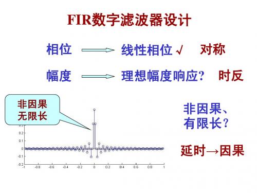
FIR数字滤波器设计 数字滤波器设计
相位 幅度
非因果 无限长
线性相位√ 线性相位√
对称 时反
理想幅度响应? 理想幅度响应
- 1、下载文档前请自行甄别文档内容的完整性,平台不提供额外的编辑、内容补充、找答案等附加服务。
- 2、"仅部分预览"的文档,不可在线预览部分如存在完整性等问题,可反馈申请退款(可完整预览的文档不适用该条件!)。
- 3、如文档侵犯您的权益,请联系客服反馈,我们会尽快为您处理(人工客服工作时间:9:00-18:30)。
修改通知状态栏的模式,修改成miui那种,在修改设置的时候手指就可以更方便了。
去除摄像机在拍照和录像时候亮度自动调到最大的问题。
修复sp9不显示hpasd+网络模式的问题。
修改状态栏上面的按钮的宽度的颜色。 提高通话音量来自点10%左右吧,再高提高不了了
修复 设置-显示-旋转 可能会导致卡死,需要重启才能恢复的问题
第三方相机比如Camera360只要关闭自动聚焦就可以使用了,sp9的时候如果没有关闭自动聚焦,照相的时候会卡死,现在设成照相的时候没有反映。
修复相机设置界面过度透明的问题
备份好资料
不连接电脑
手机关机
按音量下+挂机+电源 进入白色华为界面不动
连接电脑
运行windows 2.3.bat
自动重启
修改设置里面的选项,删除一些u8500用不上的东西,将cm设置改成高级设置
高级设置-界面-通知栏界面-控制栏按钮 的默认设置(原来是wifi,蓝牙,GPS,声音,新增gprs和亮度)和亮度的自动/最暗这个级别。
删除原来的cpu超频设置的软件,现在可以在 设置-高级设置-性能-CPU设置里面设置了,默认设置的是49-600,可以手动修改数值到672。
所有和亮度有关的设置的最低亮度改成0了(原来是20)
耗电量恢复正常
降低媒体播放的cpu
优化内核省电效果
修复建立锁屏手势会崩溃的问题
修复一切和耳机有关的问题(微信用耳机有时候在听筒播放的问题;耳机打电话修复至完美,可以在打电话中途随意抽插;录音机有时候在听筒播放的问题,等等)
优化GPS
EXT234和SWAP都还是支持的,sp8的那个data2sd.zip也可以刷,但是我个人来说不推荐使用data2sd或者app2ext的,还是使用android自带的那个吧,如果一定要用,请自行修改添加,并注意备份你的数据。
