ABB断路器30%控制电压分闸故障浅析
ABB ControlMaster CM10、CM30、CM50和CM15零件列表说明书
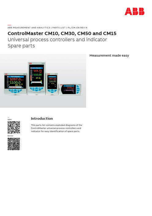
—A B B M E A SU R EM ENT A N D A N A LY TI C S | PA RTS LIS T | PL/CM -EN R E V NControlMaster CM10, CM30, CM50 and CM15Universal process controllers and indicator Spare partsMeasurement made easyIntroductionThis parts list contains exploded diagrams of the ControlMaster universal process controllers and indicator for easy identification of spare parts.—SalesService2CO NTRO LM A S TE R CM10, CM30, CM50 A N D CM15 SPA R E PA RTS | PL/CM R E V. N —Parts identificationCM10Figure 1 Identification of parts — CM103 CO NTRO LM A S TE R CM10, CM30, CM50 A N D CM15 SPA R E PA RTS | PL/CM R E V. NItem No.Description Part number 1Snap rivet B11780 2Battery B12792 3Type 1 function key (including items 1, 2, and 4)CM30/0706 4Function key support CM30/01205Mainboard CM30/0701 Mainboard (24 V DC)CM30/07026RS485 communications module upgrade kit CM30/0708 Ethernet communications module upgrade kit CM30/07097Option board 1a (1 relay)CM30/0703 Option board 1 (1 analog O/P, 2 digital I/O and 3 relays)CM30/07048Single panel clamp assembly CM10/0711 9Case moulding CM10/0056 10Thermistor assembly CM30/0052 11Panel seal CM10/0106 12Terminal cover CM10/0115 13Ethernet cable assembly CM30/0070P 14Bezel release tool CM30/0114 15Snap rivet B12722 16Bezel seal (including display dust gasket)CM10/0105 17Switch extender CM10/0107 18Bezel CM10/005319Membrane overlay CM10/0180 Membrane overlay (blank)CM10/018120O-ring B12794 21Light guide CM30/0112 22Display and processor board assembly CM10/0700Key to Figure 14CO NTRO LM A S TE R CM10, CM30, CM50 A N D CM15 SPA R E PA RTS | PL/CM R E V. N —...Parts identificationCM15Figure 2 Identification of parts – CM155 CO NTRO LM A S TE R CM10, CM30, CM50 A N D CM15 SPA R E PA RTS | PL/CM R E V. NItem No.Description Part number1Membrane overlay CM15/0180 Membrane overlay blank CM15/01812O-ring B12794 3Bezel moulding (including display dust gasket)CM15/0053 4Light guide CM30/0112 5Bezel seal CM10/0105 6Switch extender CM15/0107 7Display and processor board assembly CM15/0700 8Snap rivet B12722 9Type 1 function key (including items 11, 12 and 13)CM30/0706 10Type 2 function key CM30/0707 11Function key support CM30/0120 12Snap rivet B11780 13Battery B1279214Mainboard CM30/0701 Mainboard (24 V DC)CM30/070215Single panel clamp assembly CM10/0711 16Terminal cover CM10/0115 17Ethernet cable assembly CM30/0070P 18Panel seal CM10/0106 19Thermistor assembly CM30/0052 20Case assembly CM10/005621RS485 communications module upgrade kit CM30/0708 Ethernet communications module upgrade kit CM30/070922Option board 1a (1 relay)CM30/0703 Option board 1 (1 analog O/P, 2 digital I/O and 3 relays)CM30/070423Bezel release tool CM30/0114 Key to Figure 26CO NTRO LM A S TE R CM10, CM30, CM50 A N D CM15 SPA R E PA RTS | PL/CM R E V. N —...Parts identificationCM30Figure 3 Identification of parts – CM307 CO NTRO LM A S TE R CM10, CM30, CM50 A N D CM15 SPA R E PA RTS | PL/CM R E V. NItem No.Description Part number 1Snap rivet B11780 2Battery B12792 3Type 1 function key (including items 1, 2 and 5)CM30/0706 4Type 2 function key CM30/0707 5Function key support CM30/01206Mainboard CM30/0701 Mainboard (24 V DC)CM30/07027RS485 communications module upgrade kit CM30/0708 Ethernet communications module upgrade kit CM30/07098Option board 1a (1 relay)CM30/0703 Option board 1 (1 analog O/P, 2 digital I/O and 3 relays)CM30/07049Option board 2 (2 analog I/P and 4 digital I/O)CM30/0705 10Single panel clamp assembly CM30/0711 11Terminal cover CM30/0115 12Panel seal CM30/0106 13Thermistor assembly CM30/0052 14Ethernet cable assembly CM30/0070P 15Case assembly CM30/0056 16Bezel release tool CM30/0114 17Snap rivet B12722 18Bezel seal CM30/0105 19Switch extender CM30/0107 20Bezel assembly (including display dust gasket)CM30/005321Membrane overlay CM30/0180 Membrane overlay blank CM30/018122O-ring B12794 23Light guide CM30/0112 24Display and processor assembly CM30/0700Key to Figure 38CO NTRO LM A S TE R CM10, CM30, CM50 A N D CM15 SPA R E PA RTS | PL/CM R E V. N —...Parts identificationCM50Figure 4 Identification of parts – CM509 CO NTRO LM A S TE R CM10, CM30, CM50 A N D CM15 SPA R E PA RTS | PL/CM R E V. NItem No.Description Part number 1Type 1 function key (including items 2, 3 and 5)CM30/0706 2Snap rivet B11780 3Battery B12792 4Type 2 function key CM30/0707 5Function key support CM30/01206Mainboard CM50/0701 Mainboard (24 V DC)CM50/07027RS485 communications module upgrade kit CM30/0708 Ethernet communications module upgrade kit CM30/07098Option board 1 (2 analog I/P, 4 digital I/O, 1 analog O/P and 2 relays)CM50/0703 9Single panel clamp assembly CM30/0711 10Case assembly CM50/0056 11Panel seal CM50/0106 12Terminal cover CM50/0115 13Thermistor assembly CM30/0052 14Ethernet cable assembly CM30/0070P 15Bezel release tool CM30/0114 16Snap rivet B12722 17Display and processor board assembly CM50/0700 18Bezel seal CM50/0105 19Switch extender CM30/0107 20Bezel moulding (including display dust gasket)CM50/005321Membrane overlay CM50/0180 Membrane overlay blank CM50/018122O-ring B12794 23Light guide CM30/0112Key to Figure 410CO NTRO LM A S TE R CM10, CM30, CM50 A N D CM15 SPA R E PA RTS | PL/CM R E V. N—Service / Upgrade kitsCommonDescription Part number Type 1 function key upgrade kit CM30/0706 Type 2 function key upgrade kit CM30/0707 Rs485 communications upgrade kit CM30/0708 Ethernet communications upgrade kit CM30/0709 ConfigPilot PC configuration kit CM30/0715 IrDA bracket CM30/0716CM10, CM15 and CM30Description Part number Main board replacement kit CM30/0701 Main board replacement kit (24 V DC)CM30/0702 Option board 1a – single relay option upgrade kit CM30/0703 Option board 1 – 1 analog O/P, 2 digital I/O and 3 relay option upgrade kit CM30/0704CM10 and CM15Description Part number DIN rail mounting kit CM10/0715 Single panel clamp assembly CM10/0711CM30 and CM50Description Part number Single panel clamp assembly CM30/0711CM10Description Part number Display and processor board replacement kit CM10/0700CM15Description Part number Display and processor board replacement kit CM15/0700CM30Description Part number Display and processor board replacement kit CM30/0700 Option board 2 – 2 analog I/P and 4 digital I/O CM30/0705CM50Description Part number Display and processor board replacement kit CM50/0700 Main board replacement kit CM50/0701 Main board replacement kit (24 V DC)CM50/0702 Option board 1– 2 analog I/P, 1 analog O/P, 4 digital I/O and 2 relay option upgrade kit CM50/070311 CO NTRO LM A S TE R CM10, CM30, CM50 A N D CM15 SPA R E PA RTS | PL/CM R E V. NManualsDescription Part number User manual (base functionality) – CM10, CM30 and CM50IM/CM/B-EN User manual (standard functionality) – CM10, CM30 and CM50IM/CM/S-EN User manual (extended / dual functionality) – CM30 and CM50IM/CM/ED-EN User manual (indicator functionality) – CM15IM/CM/I-EN Communications supplement – CM10, CM15, CM30 and CM50IM/CM/C-EN PackagingDescription Part number CM30 and CM50 outer box CM30/0008 CM30 and CM50 outer box (unprinted)CM30/0009 CM30 and CM50 internal insert CM30/0010 CM10 and CM15 outer box CM10/0008 CM10 and CM15 outer box (unprinted)CM10/0009P L /C M R e v . N 05.2023—ABB Measurement & Analytics For your local ABB contact, visit:/contactsFor more product information, visit:/measurement—We reserve the right to make technical changes or modify the contents of this document without prior notice. With regard to purchase orders, the agreed particulars shall prevail. ABB does not accept any responsibility whatsoever for potential errors or possible lack of information in this document.We reserve all rights in this document and in the subject matter and illustrations contained therein. Any reproduction, disclosure to third parties or utilization of its contents – in whole or in parts – is forbidden without prior written consent of ABB.©ABB 2023All rights reserved.。
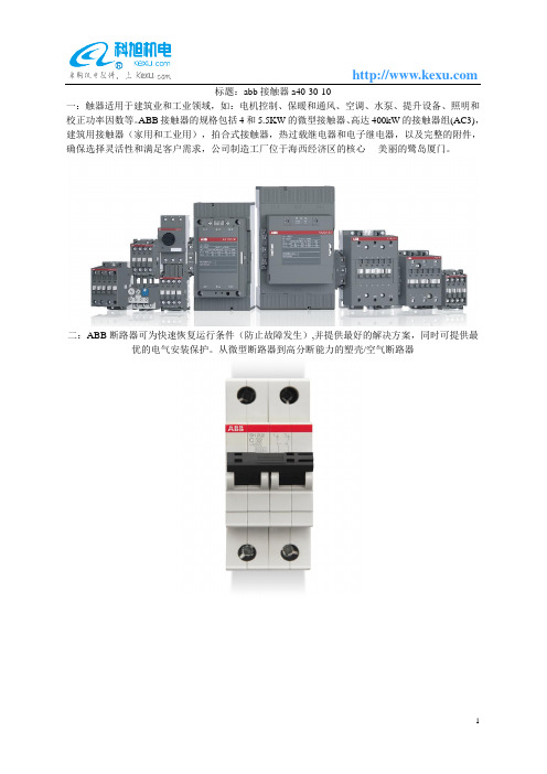
abb接触器a40-30-10
标题:abb接触器a40-30-10
一:触器适用于建筑业和工业领域,如:电机控制、保暖和通风、空调、水泵、提升设备、照明和校正功率因数等。
ABB接触器的规格包括4和5.5KW的微型接触器、高达400kW的接触器组(AC3),建筑用接触器(家用和工业用),拍合式接触器,热过载继电器和电子继电器,以及完整的附件,确保选择灵活性和满足客户需求,公司制造工厂位于海西经济区的核心----美丽的鹭岛厦门。
二:ABB断路器可为快速恢复运行条件(防止故障发生),并提供最好的解决方案,同时可提供最优的电气安装保护。
从微型断路器到高分断能力的塑壳/空气断路器
三:小型断路器多级:ABB断路器可为快速恢复运行条件(防止故障发生),并提供最好的解决方案,同时可提供最优的电气安装保护。
从微型断路器到高分断能力的塑壳/空气断路器
四:变频器主要用于控制和调节三相交流异步电机的速度,并以其稳定的性能、丰富的组合功能、高性能的矢量控制技术、低速高转矩输出、良好的动态特性及超强的过载能力,在变频器市场占据
着重要的地位。
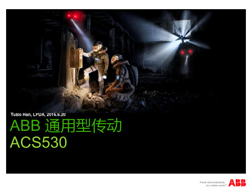
ABB变频器ACS530产品样本_
控制盘接口 CCA-01接口 插槽 1 接口
§
支持F系列总线适配器
© ABB Group June 21, 2016 | Slide 18
硬件概况 基本型控制盘
§
标配基本型控制盘 图型化菜单方便用户调试 内置LCD显示 支持参数备份还原 预制多种宏,方便设置参数
§
§
§
§
© ABB Group June 21, 2016 | Slide 19
ABB 通用型传动 共享全兼容元素
§ •
共享控制界面 图形化菜单调试
§ • • • •
免费入门级PC工具 快捷通用的连接和设置 便捷监控 一键诊断 专业版享有更多功能
§ • •
通用连接性 通用的总线模块 通用的接线端子
§ • •
紧凑且实用的设计 更轻、更小 通用连接端子
© ABB Group June 21, 2016 | Slide 5
ABB 通用型传动 向下兼容 – 无需多虑
© ABB Group June 21, 2016 | Slide 7
ABB 通用型传动 引领潮流
§
功率和电压等级:
§
0.75kW - 250kW
§
3-相 380 - 480V
§
壁挂式安装,防护等级:
§
IP20 图形化菜单调试 绿色环保包装、部分材质来自于循环再利用材 料
§
© ABB Group June 21, 2016 | Slide 27
软件调试 “ 选项 ” 菜单 - 设置频率给定值
§ §
1. 按箭头按钮可设置频率。 2. 按确定按钮可确认更改。
© ABB Group June 21, 2016 | Slide 28
ABB A系列接触器

Terminals at the same level as other system components
ABB,X Cˆ < , ,X ’h G ‘&`4»+ <,X ]>
Contactor fits perfectly with ABB breakers, switch fuses and overload relays
Completely protected connections
IP20 from front
IP20
© ABB Group - 32 30-Apr-07
ABB A2ˇ º y?” < 2ˇ
Co-ordination contactors - Isomax breakers Co-ordination contactors - Isomax breakers
© ABB Group - 1 30-Apr-07
A 2ˇ º y?” <
© ABB Group - 2 30-Apr-07
ABB A
ABB A
A 9, A 12, A 16
A 26, A 30, A 40 A(F)50, A(F)63, A(F)75 A(F)95, A(F)110
© ABB Group - 3 30-Apr-07
50%
80% " „ 0+
" „ 0+ _
_
ABB AF2ˇ º y?” < 2ˇ
(
)
AF400 „ y?” < ˆ ,¨ y+ PLC {
© ABB Group - 20 30-Apr-07
ABB AF2ˇ º y?” < 2ˇ
ABB机器人简介
ABB机器人的组成之阿布丰王创作IRB型机器人是著名的瑞典机器人生厂商ABB公司的产品,IRB指ABB尺度系列机器人。
IRB机器人经常使用于焊接、涂刷、搬运与切割。
经常使用的型号有:IRB 1400,IRB 2400,IRB 4400,IRB 6400。
其型号的解释如下:IRB指的是ABB机器人。
第一位数(1,2,4,6)指机器人的大小。
第二位数(4)指的是属于S4或S4C系统。
无论是何种型号,机器人控制部分基底细同。
IR 1400:承载较小,最大承载为5kg,经常使用于焊接。
IRB 2400:承载较小,最大承载为7kg ,经常使用于焊接。
IRB 4400:承载较大,最大承载为60kg 经常使用于搬运或大范围焊接。
IRB6400:承载较大,最大承载为200kg,经常使用于搬运或大范围焊接。
ABB机器人的组成:ABB机器人是由两部分组成:机械手和控制器。
操纵人员通过控制器操纵机械人。
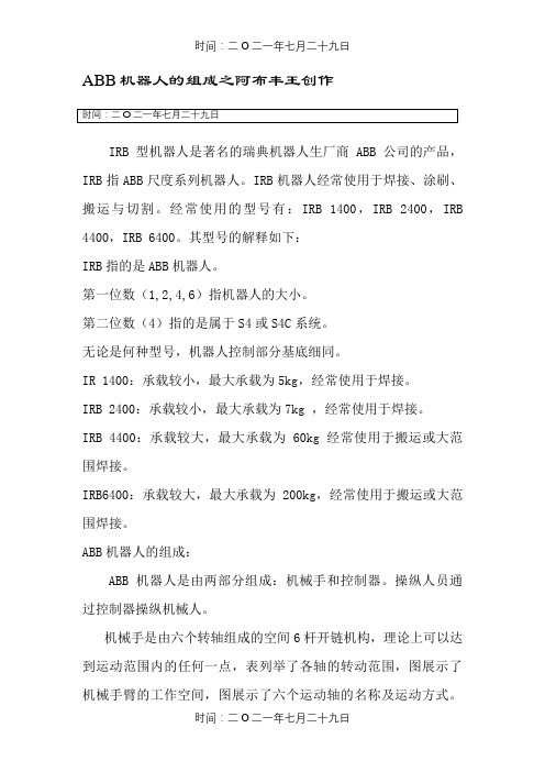
机械手是由六个转轴组成的空间6杆开链机构,理论上可以达到运动范围内的任何一点,表列举了各轴的转动范围,图展示了机械手臂的工作空间,图展示了六个运动轴的名称及运动方式。
每个转轴均带有一个齿轮箱,机械手运动精度可达到±0.05mm~±0.2mm 。
六个转轴均有AC 伺服电机驱动。
机械手带有一块串口丈量板(SMB ),它将编码器模拟量装换为数字量,并依靠刘杰可充电镍铬电池供电,机器人关机时,通过电池存储机器人当前编码器位置,一旦电池电量缺乏需要及时更换。
ABB 机器人的控制器如下图所示:控制器系统主要由主计算机板、机器人计算机板、快速硬盘、网络通信计算机、示教器、驱动单元、通信单元和电力版组成。
变压器、主计算机、轴计算机、驱动板、串口丈量和编码器组成伺服驱动系统,对位置、速度和电机电流进行数字化调整,对电机叫了控制进行同步。
机器人系统从串行丈量板连续的接收机器人新的数据位置,输入位置调整器中,与先前的位置数据进行比较和放大,输出新的位置和速度控制。
接触器UA50-30-00
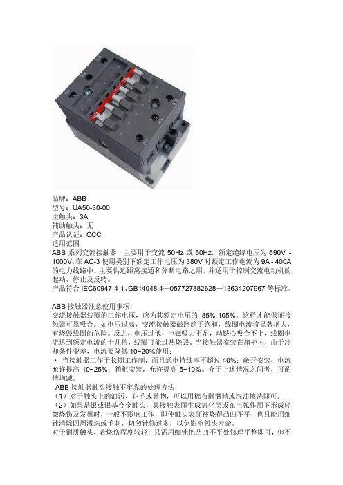
品牌:ABB型号:UA50-30-00主触头:3A辅助触头:无产品认证:CCC适用范围ABB系列交流接触器,主要用于交流50Hz或60Hz,额定绝缘电压为690V - 1000V,在AC-3使用类别下额定工作电压为380V时额定工作电流为9A - 400A 的电力线路中。
主要供远距离接通和分断电路之用,并适用于控制交流电动机的起动、停止及反转。
产品符合IEC60947-4-1、GB14048.4—0577********—136********等标准。
ABB接触器注意使用事项:交流接触器线圈的工作电压,应为其额定电压的85%-105%,这样才能保证接触器可靠吸合。
如电压过高,交流接触器磁路趋于饱和,线圈电流将显著增大,有烧毁线圈的危险。
反之,电压过低,电磁吸力不足,动铁心吸合不上,线圈电流达到额定电流的十几倍,线圈可能过热烧毁。
当接触器安装在箱柜内,由于冷却条件变差,电流要降低10~20%使用;·当接触器工作于长期工作制,而且通电持续率不超过40%;敞开安装,电流允许提高10~25%;箱柜安装,允许提高5~10%。
介于上述情况之间者,可酌情增减。
ABB接触器触头接触不牢靠的处理方法:(1)对于触头上的油污、花毛或异物,可以用棉布蘸酒精或汽油擦洗即可。
(2)如果是银或银基合金触头,其接触表面生成氧化层或在电弧作用下形成轻微烧伤及发黑时,一般不影响工作,即使触头表面被烧得凸凹不平,也只能用细锉清除四周溅珠或毛刺,切勿锉修过多,以免影响触头寿命。
对于铜质触头,若烧伤程度较轻,只需用细锉把凸凹不平处修理平整即可,但不允许用细砂布打磨,以免石英砂粒留在触头间,而不能保持良好的接触;若烧伤严重,接触面低落,则必须更换新触头。
(3)运动部分有卡阻现象,可拆开检修。
常用型号:———————————UA16-30-10R切换电容接触器UA26-30-10R切换电容接触器UA30-30-10R切换电容接触器UA50-30-00R切换电容接触器UA63-30-00R切换电容接触器UA75-30-00R切换电容接触器UA95-30-11 切换电容接触器UA110-30-11 切换电容接触器A9-30-10(/01)4kW 线圈电压:24/110/220/380A12-30-10(/01 5.5kW 线圈电压:24/110/220/380A16-30-10(/01)7.5kW 线圈电压:24/110/220/380 A26-30-10(/01)11kW 线圈电压:24/110/220/380A30-30-10(/01)15kW 线圈电压:24/110/220/380A40-30-10(/01)18.5kW 线圈电压:24/110/220/380A50-30-11 22kW 线圈电压:24/110/220/380A63-30-11 30kW 线圈电压:24/110/220/380A75-30-11 37kW 线圈电压:24/110/220/380A95-30-11 45kW 线圈电压:24/110/220/380A110-30-11 55kW 线圈电压:24/110/220/380A145-30-11 75kW 线圈电压:24/110/220/380A185-30-11 90kW 线圈电压:24/110/220/380》A210-30-11 110kW 线圈电压:24/110/220/380A260-30-11 140kW 线圈电压:24/110/220/380A300-30-11 160kW 线圈电压:24/110/220/380。
ABB软启动器PSS说明#

ABB软启动器的型号、选用说明以及功能一、三大系列。
普通型PSS智能型(带微处理器,不带内置旁路接触器)PST智能型(带微处理器,带内置旁路接触器)PSTB二、两种电压规格软启动器主回路电压,以PSS型为例,样本上红色标记的,主回路230-500V,对应的型号是-500系列;主回路400-690V,对应的型号是-690V系列。
通常我们国家的工业电压是380V,所以应该选-500系列。
-690V贵很多。
电机额定电压,有400V,500V,690V三种规格,通常我们国家是400V三、平时我们经常说额定功率,其实实际上是用额定电流来选型,样本上列出的是标准电机额定功率对应的额定电流。
四、内接还是外接内接可以降低一个容量来选用软启动器,或说可以启动高一个容量的电机。
以PSS18/30-500的软启动器为例,外接是18A的额定电流,对应的是7.5W的标准电机;内接是30A的额定电流,对应的是15W的标准电机。
五、软启动器的功能为了适应现代化生产,为减少对电网的冲击。
对机械的磨损。
减少对启动装置的维护。
可调启动电流。
可校调启动转矩。
可软停车的软启动器被广泛应用于鼠龙型电动机的启动,现以ABB公司软启动器为例:详细介绍其功能及特性。
ABB公司软启动器有以下规格型号:PSS03—25—500L两相控制适用于小型电机的紧凑设计。
这种小型软启动器具有内置的旁路触点。
可长期带负载运行。
PSSI8/30一PSS142/245适用于普通性负载。
同一装置可用“外接”和“内接”两种连接方法(图二)。
采用内接可减少42%流经软启动器的电流。
也就说使用户有可能用58A的软启动器来控制和运行IOOA的电机。
限流功能为可选件。
因此其启动特性有两种设定:1)无限定启动电流时:可设定启动时间(O一3os),启动电压(3O%一70%Ue)其起动曲线见图三。
2)有限定启动电流:需外接数个电流互感器(变化为/1),可设定启动时间,启动电流倍数。
ABB隔离开关_OT
目录
页
产品概述 ............................................................................................... 1-2
技术数据 OT16-160 ..................................................................................... 3-4 OT200-800 ....................................................................................... 5 OT1000-1600 ................................................................................... 6 OETL2500-3150 ................................................................................ 6
造性和紧凑形的操作机械机构。 • 独特的超短电流路径设计,确保了紧凑的触头机构。
SwitchLine (OT、OETL)
产品概述
OT在太阳能光伏的应用
全新的1000V DC OT系列隔离开关是为了对太阳能 光伏系统中的直流分断问题而专门设计的。在直流 1000V DC时,仍具有出色的分断能力,可应用于 太阳能系统的各级汇流箱、逆变器以及电池系统, 为系统的分断和隔离提供解决方案。其优越的性能 和安全的设计,遥遥领先于市场同类产品。并在欧 州以及美国的各类光伏项目中获得广泛的应用和认 可。它不但兼备3极和4极开关的优点,而且还具备 以下优点: • 额定电压高达1000V(DC21条件下) • 额定电流16-630A • 紧凑的结构、卓越的性能
ABB软启动器PS18 PS30 PS300 PS515维修手册(PDF 16页)

2Contents 目 錄Softstarter Marking 3Mounting 4Drilling plan 4Minimum distance to wall/front 4Connection 5Main circuit Bar 1L1, 3L2, 5L3 as well as 2T1, 4T2 and 6T35Control voltage and control circuit 6Setting 9Start ramp 9Stop ramp 9Initial voltage (U INI ) / Current limit function (I LIM)9Switch for selection of connection type,Line/Delta switch S110Basic settings for different applications 11Maintenance 12Trouble Shooting 12Technical Data 15Dimensions 15Circuit diagram 161. 軟起動器鉻牌2. 安裝2.1 開孔圖2.2 對牆 / 面板的最小距離3. 接線3.1 主回路接端子 1L1, 3L2, 5L3以及 2T1, 4T2 和 6T33.2 控制電壓和控制回路4. 設定4.1 起動曲線4.2 停止曲線4.3 初始電壓 (U INI ) / 限流功能 (I LIM)4.4 連接方式選擇開關,外接 / 內接開關 S14.5 不同應用的基本設定5. 維護6. 故障尋跡7. 技術參數7.1 尺寸7.2 電路圖1. 軟起動器鉻牌 Softstarter MarkingThese softstarters fulfil thedemands according to 89/336/EECand EN 60947-4-2 / IEC 60947-4-2,Equipment class A.!工作電壓 Us控制回路的端子標誌軟起動器型號Softstarter Type狀態指示main circuit訂貨號Order code:Ie = 72A:不帶有旁路without by-pass: 8*Ie in 1.6 秒sec: 80% 負載率及每小時起動 6 次80% in operationand 6 starts/h技術參數Technical data acc. to UL 508產品系列號Serial number 圖 Picture 1.1本軟起動器符合 89 / 336 /EEC 和 EN 60947-4-2 /IEC 60947-4-2,A 級設備的要求。
ABB--隔离开关
3/28
FuseLine 低压熔断器
3/30
外形尺寸 正面操作 侧面操作 附件
3/31 3/38 3/40
手柄指示、触头功能
3/43
开关类产品 应用场合
1 开关负荷,安全隔离
开关类产品的特点 隔离开关 OT,OTM,OTDC —— 看得见的安全 - 可视触头技术提供高级别的安全保证 - 满足隔离要求,保证人身安全 - 可带负荷操作 - 可带电动操作机构,适合远程操控应用
- 额定电压高达1000V(DC21条件下)
- 额定电流16-1600A
- 紧凑的结构、卓越的性能
ABB丨开关类产品丨1SXF300001C2001 1/2
2
2/1 1SXF300001C2001丨ABB丨开关类产品
隔离开关系列 16 - 4000 A, 690 V
90˚ 45˚
0˚
结构紧凑,性能卓越
2/78
开关类产品 目录
Hale Waihona Puke 隔离开关熔断器组(PowerLine) - OS
产品概述 产品一览表 型号说明
3
3/1 3/5 3/6
技术数据 OS32G...OS160G OS250...OS1250 OS60...200J(UL/CSA)
3/7 3/8 3/10
订货资料 正面操作 侧面操作
3/11 3/14
AC-21A AC-22A AC-23A
DC-21A
DC-22A
DC-23A
额定功率 (这些值仅供参考,可能因电机 制造商不同而有所差别)
额定分断能力
额定分断能力 / 极间串联
AC-23A AC-23A DC-23A
额定限制短路电流Ip (R.M.S) 和相应最大截断电流峰值 îc
ACS530控制链图
通常由于电机或电机电缆故 障,变频器检测到负载失衡。
确认电机电缆中没有功率因素校正电容器 或电涌吸收器。
通过测量电机和电机电缆的绝缘电阻来检 查电机或电机电缆中的接地故障。参见变 频器硬件手册中电气安装一章检查装配绝 缘一节。如果发现接地故障,请修复或更 换电机电缆和 / 或电机。 如果检测不到接地故障,请联系当地的 ABB 代表。
温度过高
电源单元模块温度超过限制。
检查环境条件。 检查气流和风机的运转。 检查散热器片,除去其中沉积的灰尘。 对比变频器功率检查电机功率。
温差过大 PCB 板冷却
不同相的 IGBT 温差过大。
环境和变频器模块 PCB 板之间 的温差过大。
检查电机接线。 检查变频器模块的冷却。
检查 PCB 板内部的冷却风机。
252 故障跟踪
注意,部分故障需要先重启控制单元 ( 方法是关闭电源再打开电源,或使用参数 96.08 控制板启动 ),此步骤在故障列表 ( 如适用 ) 中有所提及。
单纯事件
除了报警和故障之外,一些单纯的事件会记录在变频器的事件记录中。事件代码可以 参见 报警信息 表格 ( 第 253 页 )。
检查电机和电机电缆 ( 包括相位和三角 / 星形连接 )。
通过测量电机和电机电缆的绝缘电阻来检 查电机或电机电缆中的接地故障。参见变 频器硬件手册中电气安装一章检查装配绝 缘一节。
检查电机电缆中是否尚有正在打开或正在 关闭的接触器。
检查参数组 99 电机数据 中的启动数据是 否与电机额定值铭牌一致。
安全
报警!只有具备资质的电气工程师才允许对变频器进行维护。在对变频器进行 操作之前,请阅读变频器硬件手册 开头部分的安全须知 一章中的说明。
ABB隔离开关_OS系列尺寸

VI RVC/RVT
OS
S203-C25 3×OVR BT2 40-440 P
熔断器式隔离开关(方形)
熔断器式隔离开关(方形)
接触器
接触器
电抗器
电抗器
低压电容器
低压电容器
OS隔离开关熔断器组的优点:
● 可灵活配置各种电流规格的熔断器,实现高分断的可靠保护 ● 具备保护(尤其高电压高分断场合)和隔离功能 ● 电容补偿大多在一/二级配电,短路电流较高,熔断器可有效切断这些短路电流 ● 熔断器可躲过电容投切时高达100倍的冲击电流 ● 熔断器可承载连续1.5倍的额定电流 (包含谐波) ● 可以承受持续8小时1.1倍的工作电压正常波动
尺寸图 正面操作 ..................................................................................... 23-29 侧面操作 ..................................................................................... 30-31 附件 ............................................................................................ 32-33
第四极 N1: 开关中性极(位于开关左侧) N2: 开关中性极(位于开关右侧) F : 熔断器中性极
极数 2极 : 11、02 3极 : 12、03、30 4极 : 22、04、40 第一位数字表示在机械机构左边的极数 第二位数字表示在机械机构右边的极数
操作机构位置 空白 : 正面操作 S : 侧面操作
ACS6000 Training

current will isn’t sine wave, the peak current will damage the IGCT
and diode.
© ABB Group April 30, 2020 | Slide 23
The transformer saturation,the input current have the peak ,isn’t sine wave.
COU
PFF board
▪ PFF: Power Feed Forward.
Communication between the control board
PFF
AMC3x of the master INU and the DC bus
(ARU) AMC3x control board.
PFF ARU PFFe 2 sets of ASE, the purpose of the Anti Saturation Equipment is to protect the main transformer against overheating. ASE-boards measures the DC-component of the input current.
XXX, March 2018
ACS6000
Hardware ,Operation & Maintenance Personal document, unofficial
Program
▪ Active Rectifier and Inverter Unit ▪ Terminal Unit & Control Unit ▪ Capacitor Bank Unit ▪ Excitation Unit ▪ Water Cooling Unit ▪ Control Logic ▪ Protection concept ▪ Operation ▪ Maintenance
ABB低压产品常用型号说明及订货明细

ABB常用型号说明针对现在有很多业务员反映看不懂ABB面价表,里面的型号有很多相似之处,客户又没特殊要求,常用的型号根本不知道怎么选。
在此,特对我们最常用型号做如下说明及订货输入方式。
一、接触器1、选型必要参数:清楚电流大小,极数,触点方式及工作电压,就可以选型。
如额定工作电流为110A,主回路3极,1常开1常闭,工作电压是220V。
则可以选型为A110-30-11 AC220V2、如何在面价表中查询:我们在04年ABB低压产品面价表中工作电压为220V的正确型号也是最常用的型号应该为A110-30-11*220-230V50HZ,所以在面价表中选接触器时,都要以这样的型号为准,除客户特殊要求。
我们库存型号如:A110-30-11 AC220V,这个型号就是面价表中的A110-30-11*220-23050HZ,现在出现业务员订A110-30-11*220V50HZ,可能就会看到为什么处理的货期这么长,220V的不是很常用的吗?我们的解释是,这是两个完全不同的型号,你已经订错货了,此为不常用型号。
所以请各位在选型时看清楚常用型号,如果是要220V,就必须在价格表中找220-230V50HZ的,以免订错货物承担库存。
以下是交流接触器在面价表中的几个电压等级正确型号:24V————A110-30-11*24V50HZ110V————A110-30-11*110-115V50HZ220V-------A110-30-11*220-23050HZ380V————A110-30-11*380-400V50HZ3、订货输入要求:型号输入:A110-30-11 AC220V型号就这样输入,但品名必须要输入220-230V所对应的物料号,虽然我们没有输入220-230V,但物料号一定不能错。
要和自己订的型号完全一致。
二、热过载继电器1、过载继电器在价格表中如TA25DU1.0和TA25DU1.0 V1000,同是1.0的就有两个型号,就纳闷了,我到底应该选哪个呢,导致无法确认?现在明确的说明,选TA25DU1.0,所有的热继都不要去管带V1000的,包括我们库存型号也是一样的。
ACS530-01 硬件手册说明书

安全说明连接到供电网络。
有关如何处理的信息,请参见ACS530-01 硬件手册(3AXD50000727803 [ 中文])的电气安装一章。
连接动力电缆⏹接线图⏹电机电缆如图所示准备好电机电缆的两端。
图中为两种不同的电机电缆类型 a和b。
注意:将屏蔽线裸线做360 度接地。
⏹接线步骤(当选择ABB接线盒可选件时)1.在控制板旁粘贴当地语言的残余电压警告贴纸。
2.用螺丝刀松开夹子,卸下动力电缆端子上的盖板。
3.如图所示准备输入动力电缆和电机电缆。
注意:裸露屏蔽层需 360 度接地。
使用黄绿颜色将用屏蔽层制作的尾线标记为 PE 导线。
4.将电缆穿过下固定板上的孔,电机电缆向右,输入动力电缆向左。
5.连接电机电缆:•将屏蔽层在接地夹钳下进行 360 度接地。
•将电缆的屏蔽层连接到接地端子。
•把电缆的相导线连接到端子 T1/U、T2/V 和 T3/W。
6.按照步骤5使用端子 L1、L2 和 L3连接输入动力电缆。
7.安装控制电缆的接地架。
8.装回动力电缆端子上的盖板。
9.以机械方式紧固装置外部的电缆。
10.将电机端的电机电缆屏蔽层接地。
为最大程度降低射频干扰,请将电机电缆屏蔽层在电机端子盒的引线孔处进行 360度接地。
端子尺寸:R1…R9: 0.14…1.5 mm 2(所有端子)紧固力矩:0.5…0.6 N·m (0.4 lbf·ft)注:1)该信号源由外部供电。
参见制造商的的说明。
要使用由变频器辅助电压输出供电的传感器,请参阅变频器硬件手册 中“电气安装”一章的“两线制和三线制传感器的连接示例”一节。
2)对于控制电缆,在接地夹下方的接地架上对电缆的外屏蔽层进行 360 度接地。
3)出厂时已通过跳线连接。
4)注:对数字信号使用屏蔽双绞线。
安装可选模块(如果有)参见 ACS530-01 硬件手册(3AXD50000727803 [ 中文])的电气安装一章。
启动和使用要启动变频器,您需要设置电机数据、电机控制、连接宏和变频器参数。
abb与施耐德,西门子低压产品对照表
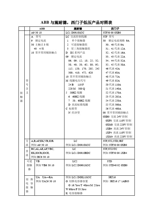
32、42代表16A
33、43代表22A
34、44代表32A
35、45代表38A
46代表45A
47代表63A
48代表75A
49代表85A
50代表110A
51代表140A
52代表170A
53代表205A
54代表250A
55代表300A
56代表400A
00常开常闭辅助触点
0XB0交流24V控制
D/O抽出式F;固定式
MIC 2.0A控制单元:
2.0—LI 5.0—LSI
6.0—LSIG 7.0—LSIG+漏电A—电流表P—功率表H—谐波表
附件:COM:通讯选件
MCH:电动机构
MX:分离线圈
XF:合闸线圈
MN:欠压线圈
VO:安全挡板
CDP:门框
CB:二次接线端子盖板PF:“准备合闸”触点
3WT型号
TMA热磁式可调
电动机保护
热磁式:
MF热磁式不可调
MA热磁式可调
电子式:
ER11 LSI
ER12LSIG
3P极数
F安装方式:
F:固定式
P:插入式
D:抽出式
附件:
PB:插入式底座
DB:抽出式底座
MCH:电动操作机构
MX:分励脱扣
MN:欠压线圈
HS:辅助开关
AS:报警开关
带漏电保护的塑壳断路器
T开关需加装RC221或RC222
例如BC6-30-10
LC
例如LC1-D0910BDC
3TF,3TS3TC
例如3TF30 00-1XB4
可逆接触器
VB
例如VB6-30-10
ABB电梯控制模块M2306 M2307说明书

ABB-WelcomeLift control module M2306M23071Safety (3)2Environment (3)2.1ABB devices (3)3Technical data (4)4Function (5)5Connection (6)5.1M2306 (6)5.2M2307 (7)5.3Lift control relay module address by binary setting (9)6Mounting / Installation (10)6.1Requirements for the electrician (10)6.2Mounting (12)7User case (13)7.1High building (no more than 16 floors) with one lift (13)7.2High building (more than 16 floors) with one lift (15)7.3High building (more than 16 floors) with two lifts (17)7.4High building (more than 16 floors) with four lifts (18)8Operation (19)8.1User scenario illustration of visitor target floor (19)8.2User Scenario Illustration of resident target floor (20)9Configuration through PC software (21)9.1Connected to PC (21)9.2Configuration (22)|— 2 —1SafetyWarningElectric voltage!Dangerous currents flow through the body when coming into direct orindirect contact with live components.This can result in electric shock, burns or even death.■Disconnect the mains power supply prior to installation and/ordisassembly!■Permit work on the 110-240 V supply system to be performed only by specialist staff!2EnvironmentConsider the protection of the environment!Used electric and electronic devices must not be disposed of withhousehold waste.– The device contains valuable raw materials that can be recycled.Therefore, dispose of the device at the appropriate recyclingfacility.2.1ABB devicesAll packaging materials and devices from ABB bear the markings and test seals for proper disposal. Always dispose of the packaging material and electric devices and their components via an authorized collecting depots or disposal companies.ABB products meet the legal requirements, in particular the laws governing electronic and electrical devices and the REACH ordinance.(EU-Directive 2002/96/EG W EEE and 2002/95/EG RoHS)(EU-REACH ordinance and law for the implementation of the ordinance (EG)No.1907/2006)3Technical dataGeneralSingle-wireclamps2 x 0.28 mm - 2 x 0.75 mm; Fine-wire clamps 2 x 0.28 mm - 2 x 0.75 mm; Bus voltage20-30 V DCSize 4 TEProtection IP 20Operatingtemperature-25 °C - +55 °CSize M2306: 90 mm x 72 mm x 65 mmM2307: 216 mm x 110 mm x 45 mm4FunctionThe lift control modules include the M adaptor (M2306) and lift control relay module (M2307). These two devices together ensure that lift (elevator) only goes to authorized floor(s).If a resident presses the "unlock" button when receiving a guest's call from the outdoor station, or the authorized user swipes the registered card or enters correct password, the lift (elevator) will automatically go down to the floor where the outdoor station is installed. The lift (elevator) will then go to the dedicated floor where that resident lives. It cannot go to unauthorized floors, even when other buttons are pressed.The configuration should be done through the dedicated configuration software by connecting the M adaptor to a computer.5Connection5.1M2306Fig. 1No.Function1Status- ON = Connected with the system controller/internal bus- OFF = Not connected with the system controller/internal bus- Blinking = Working with the system controller/internal bus2- ON = Power on- OFF = Power off- Blinking = Working3Connect with M23074Power supply5Connect with the system controller/internal bus5.2M2307Fig. 2No.Function1Power LED- ON = Power on- OFF = Power off2Setting LED- Blinks when working normally3AddressSet the module addressThe address range is 1-16.Only the left 4 bits are used. 4Power supply5Connect with M23066Connect with the lift controller5.3Lift control relay module address by binary settingFig. 3·Installer needs only read the labeling on the lift control moduleand adjust according to the given position.·Only digits 1-2-3-4 are used.6Mounting/InstallationWarningElectric voltage!Dangerous currents flow through the body when coming into direct orindirect contact with live components.This can result in electric shock, burns or even death.■Disconnect the mains power supply prior to installation and/ordisassembly!■Permit work on the 110-240 V supply system to be performed only by specialist staff!WarningElectric voltage!The upstream fuse must be disconnected when working on the lighting system.6.1Requirements for the electricianWarningElectric voltage!Install the device only if you have the necessary electrical engineering knowledge and experience.• Incorrect installation endangers your life and that of the user of the electrical system.• Incorrect installation can cause serious damage to property, such asa fire.The minimum necessary expert knowledge and requirements for the installation are as follows:• Apply the "five safety rules" (DIN VDE 0105, EN 50110):1.Disconnect the power;2.Secure against being reconnected;3.Ensure there is no voltage;4.Connect to earth;5.Cover or barricade adjacent live parts.• Use suitable personal protective clothing.• Use only suitable tools and measuring devices.• Check the type of supply network (TN system, IT system, TT system) to secure the following power supply conditions (classic connection to ground, protective earthing, necessary additional measures, etc.).6.2MountingThe device must only be installed on mounting rails according to DIN EN 50022.It is highly recommended that M2306 be installed in the lift motor room on the top floor or the electrical riser, while M2307 should be installed in the lift cabin.Fig. 4Fig. 5: Dismantle7User case7.1High building (no more than 16 floors) with one lift One M2306 and one M2307Fig. 6: TopologyWiring with one M2306 and one M2307Fig. 77.2High building (more than 16 floors) with one lift one M2306 and multi (up to 16) M2307Fig. 8: TopologyWiring with one M2306 and multi M2307Fig. 9Notes:1.The first mini system controller (M2301) feeds one M2306 and one M2307.2. An additional M2307 should be locally powered by one mini system controller. Eg. with (4) M2307 and (1) M2306, 4 mini system controllers are needed.7.3High building (more than 16 floors) with two lifts one M2306 and multi M2307 support 2 liftsFig. 10: TopologyNote: The address code can not be repeated.7.4High building (more than 16 floors) with four lifts Two M2306 and multi M2307 support 4 liftsFig. 11: TopologyNote: The address code can not be repeated.8Operation8.1User scenario illustration of visitor target floorFig. 121.Visitor inputs calling code for the 12th floor.2. The resident presses the "unlock" button at any ABB-Welcome indoor station.3. The lift will go down to the outdoor station automatically when visitor enters the lift.4. Within a set of time (default of 10 minutes),the visitor can only activate the 12th floor.Other floors will not be activated at the same time.After 10 minutes, the visitor must go to the outdoor station to call the resident again.5. The visitor reaches the 12th floor.8.2User Scenario Illustration of resident target floorFig. 13Note : The lift control module will not function if the unlock button is pressed without a call from building outdoor station. E.g., unlock when there is a villa/floor outdoor station or gate station.1. The resident (living on the 12th floor)enters by inputting a password or swiping with authorized card.2. The lift will automatically go down to the outdoor station floor when the resident enters the lift.3. Within a set time (default of 10minutes), the resident can only activate the 12th floor. Other floors will not be activated at the same time.After 10 minutes, the resident must go to the outdoor station to input password or swipe card again.4. The resident reaches the 12th floor.9Configuration through PC software9.1Connected to PCDuring configuration, the lift control adaptor can be connected directly to the PC so that the installed software (ABB-Welcome PC Configuration Tool) can be used. Essentially, there is no need for local power supply during configuration.Upon completing configuration, click "Send the Configuration" to upload the configured file to the system. Refer to instructions below.Note: Only supports Microsoft WindowsFig. 149.2ConfigurationBasic StepsStep 1: Set basic parameters of the apartment using the ABB-Welcome configuration tool.Fig. 15No.Function 1Select building number.2Select floor number.3Select apartment number.4Set physical address (e.g., 13 means the IS address set by IS switches)5Set user name 6Set logic address (e.g., 0703 means 7th floor, apartment number 3).7Add data from one apartment to project.8Upload configuration to system12345678Step 2: Select building, M2307 and configure parameters of each relayFig. 16No.Function 1Select building number 2Select M2307 number 3Click “Add” to add a new M23074Select ON or OFF for connecting the relay 5Select NO or NC for output type 6Set relay operation time (1-3,600 seconds)7Show all M2307 parametersNote:In order to ensure building is configured properly, please finish each step before starting installation in a new building.1234567Step 3: Associate outdoor station with M2307Fig. 17No.Function 1Building number (same as step2)2Select outdoor station number 3Select Relay No. of M23074Click “Add” to associate outdoor station with relay 5Send all parameters to M23066Input password*. Default password is 123456.*Please write down this password. If password is forgotten, software mustbe reloaded.123456Step 4: Associate indoor station with M2307Fig. 18No.Function 1Building number (same as step2)2Select indoor station physical address 3Select relay number of M23074Select outdoor station number (floor number of outdoor station installed)5Click “Add” to associate indoor station with relay 6Send all parameters to M23067Input password. Default password is 123456.1235674Optional steps:Step 5: Export all data from this project or import data for new projectFig. 19No.Function 1Export all lift control configuration data to one read-only Excel file. (Export the lift control configuration of each building for future reference.)2Import data for a new project from Excel file12Step 6: Save as one new project1Fig. 20No.Function1Save as one new project: *.xmlStep 7: Import existing project data to new outdoor station, guard unit and lift control 1Fig. 21No.Function1Open one existing project: *.xmlNoticeWe reserve the right to, at any time, make technical changes or changes in the content of this document without prior notice.The detailed specifications agreed to at the time of ordering applies to all orders. ABB accepts no responsibility for possible errors or incompleteness in this document.We reserve all rights to this document and the topics and illustrations contained therein. The document and its contents, or excerpts thereof, must not be reproduced, transmitted or reused by third parties without prior written consent by ABB.。
ABB元件图形符号详解

一、二次图纸的种类 Sort of secondary drawings1.柜体排列图Switchgear Overall General Arrangement 代号: A1.原理图Schematic Diagrams 代号:S1.端子排图Terminal Diagrams 代号: T1.设备清单Equipment Schedule 代号: E2.逻辑图Logic Diagrams 代号: L二、开关柜的种类 Sort of switchgear开关柜按其功能分类 , 共有七种柜型The switchgear includes seven types by it's function1.进线柜Incoming Panel 代号:I1.隔离柜Disconnection Panel 代号:D1.馈线柜Feeder Panel 代号:F1.母联柜Bustie Panel 代号:B1.母线提升柜Busriser Panel 代号:R1.专用计量柜Metering Panel 代号:M1.PT 柜P.T. Panel 代号:P三、常用元器件图例符号 Legends and Symbols1.线型Line type1.1 细实线: 表示二次元器件之间的连接线及元器件的内部接线;Thin continous line : Wiring between secondary equipments and internal terminals ofequipment;1.2 细实线框: 表示同一元器件内;Thin continous line case : One equipment;1.3 粗实线: 表示一次回路电气元器件及连结线;Thick continous line : Primary circuit;1.4 粗点画线框: 表示非本柜内的元器件;Thick dash dot line case: The equipments which are not mounted in the respectivepanel;1.5 粗虚线框: 表示由用户提供的元器件;Thick hidden line case : The equipments which are supplied by customers;2.标注Annotation2.1 图纸上方标注栏的文字是用来说明其垂直区域内回路的功能;The annotation at the top of diagrams explains function of the vertical circuit;2.2 图纸中不同页间的连接线以符号, 横线下方的字符表示连接的页数,横线上方的字符表示回路代号;3.端子排的编号原则Terminal No. indentification systemX1 : 直流辅助电源小母线 D.C. Auxiliary Supply Bus(供控制和保护用) (For Control & Protection Circuit) X2 : 备用SpareX3 : 控制、保护回路Control & Protection CircuitX4 : 电流互感器二次回路 C.T. Secondary CircuitX5 : 提供给客户的信号回路Alarm & Remote Signal (For Customer Use) X6 : 电压互感器二次回路P.T. Secondary CircuitX7 : 备用SpareX8 : 变送器的输出信号回路Transducer Secondary Output CircuitX9 : 交流辅助电源小母线AC Auxiliary Supply Bus4.连线编号原则Wiring No. indentification system.编号格式举例 exampleFormat : TNNXX 34A1T : 页号 3SheetNN : 区域4AAreaXX :Series No. 1系列号5.常用元器件图例符号 Legends and SymbolsS7-300对RPBA-01通讯(ACS800变频器,标准软件)小结一、硬件安装1.硬件设备:ACS800变频器、RPBA-01模块各一, CPU314模块、PS307 5A模块、CP342-5模块、PC-ADAPTER编程电缆各一,西门子PROFIBUS总线适配器一对,PROFIBUS通讯电缆一条。
ABB变频器ACS530-ACS510替换指南
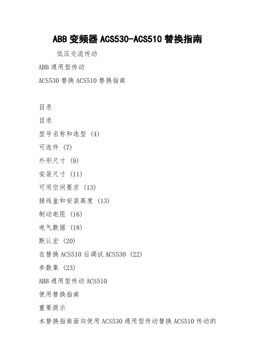
ABB变频器ACS530-ACS510替换指南低压交流传动ABB通用型传动ACS530替换ACS510替换指南目录目录型号名称和选型 (4)可选件 (7)外形尺寸 (9)安装尺寸 (11)可用空间要求 (13)接线盒和安装高度 (13)制动电阻 (16)电气数据 (18)默认宏 (20)在替换ACS510后调试ACS530 (22)参数集 (23)ABB通用型传动ACS510使用替换指南重要提示本替换指南面向使用ACS530通用型传动替换ACS510传动的ABB技术合作伙伴和客户,手册仅针对有限的用户进行分发。
ABB编制本文档来帮助销售伙伴、授权渠道合作伙伴和客户完成替换工作。
我们尽一切努力确保信息的准确性。
所有安装和电气工作都应该由受过培训的专业人员进行。
对于因为使用或选择本文档的任何信息、装置、方法、流程,或在本文档中说明的类似项目而造成的任何损害或其他责任(包括任何相应损害,即使ABB或ABB代表已告知可能造成这样的损害),ABB概不负责。
技术规格如有更改,恕不另行通知。
本指南将帮您利用ACS530通用型传动替换ACS510传动。
按照本指南介绍的步骤操作,确保您找到最佳替换产品,加速替换过程。
替换程序第1步:传动选型、选择可选件比较功率范围、安装方法和外形尺寸,根据ACS510传动选择正确的ACS530产品。
第2步:安装和布线比较外形尺寸、安装孔尺寸和电缆数据,实现最佳替换效果。
第3步:调试通过利用映射表来完成ACS530调试ABB通用型传动ACS530型号名称和选型传动选型型号名称1.首先确定您的ACS510传动的型号名称2.比较下面额定值表中电机的功率和电流额定值3.比较下页的可选件ACS510产品系列型式和结构(01=壁挂式)额定值(安培)电压ACS530产品系列型式和结构(01=壁挂式)额定值(安培)电压可选件ACS510ACS530型号名称功率kW I2N (A)外形尺寸外形尺寸I2N(A)功率(kW)型号名称----R02.60.75ACS530-01-02A6-4ACS510-01-03A3-4 1.1 3.3R13.3 1.1ACS530-01-03A3-4ACS510-01-04A1-4 1.5 4.14 1.5ACS530-01-04A0-4 ACS510-01-05A6-4 2.2 5.6 5.6 2.2ACS530-01-05A6-4 ACS510-01-07A2-437.27.23ACS530-01-07A2-4ACS510-01-09A4-449.49.44ACS530-01-09A4-4ACS510-01-012A-4 5.511.9R112.6 5.5ACS530-01-12A6-4 ACS510-01-017A-47.517R2R2177.5ACS530-01-017A-4ACS510-01-025A-411252511ACS530-01-025A-4ACS510-01-031A-41531R3R33315ACS530-01-033A-4ACS510-01-038A-418.5383918.5ACS530-01-039A-4ACS510-01-046A-422464622ACS530-01-046A-4ACS510-01-060A-43060R4R46230ACS530-01-062A-4ACS510-01-072A-437727337ACS530-01-073A-4ACS510-01-088A-44588R58845ACS530-01-088A-4ACS510-01-125A-455125R510655ACS530-01-106A-4ACS510-01-157A-475157R6R614575ACS530-01-145A-4ACS510-01-180A-490180R716990ACS530-01-169A-4ACS510-01-195A-4110205206110ACS530-01-169A-4ACS510-01-246A-4132245R8246132ACS530-01-246A-4ACS510-01-290A-4160290293160ACS530-01-293A-4----R9363200ACS530-01-363A-4----430250ACS530-01-430A-4额定值P N无过载应用时的典型电机功率。
- 1、下载文档前请自行甄别文档内容的完整性,平台不提供额外的编辑、内容补充、找答案等附加服务。
- 2、"仅部分预览"的文档,不可在线预览部分如存在完整性等问题,可反馈申请退款(可完整预览的文档不适用该条件!)。
- 3、如文档侵犯您的权益,请联系客服反馈,我们会尽快为您处理(人工客服工作时间:9:00-18:30)。
A
58.4
因此,A B B H P L 系 列 SF6 断 路来自器 3 0 % 控制电压下异常分
断路器动作电压的关键在于衔铁与辅助挚子之间的间隙。
表 2 断路器分合闸时间测定
间 隙 越 小 ,衔 铁 在 磁 力 作 用 下 加 速 行 程 越 小 ,撞 击 辅 助 挚 子 的 力度越小,挚子难以脱扣。此 时 ,动作 电 压 会 升 高 ;反 之 ,间隙 越 大 ,衔铁在磁力作用下加速行程越大,撞击辅助挚子的力度 越 大 ,挚子容易脱扣,此 时 ,动作电压会降低。然 而 ,间隙过大,
技术研发
TECHNOLOGYANDMARKET V〇1.24,N〇.9,2017
ABB断 路 器 3 0 % 控制电压分闸故障浅析
李杰
( 深 圳 供 电 局 有 限 公 司 ,广 东 深 圳 518000)
摘 要 :断路器动作特性试验数据是衡量断路器能否正常运行的重要参数。就 近 期 深 圳 地 区 出 现 的 A B B H P L 系 列 SF6 断路器在动作特性试验中,断路器在3 0 % 控制电压下异常分闸的问题进行分析,找 出 故 障 根 本 原 因 ,提出调整分闸线圈 衔铁间隙以及更换分闸挚子两种解决办法,有效消除了此类故障,确保断路器安全可靠运行。 关 键 词 :A B B 断路器;弹簧机构;动作特性;分闸挚子 doi:10. 3969/j .issn.1006 - 8554.2017. 09. 047
分 闸 线 圈 动 作 ,导 致 分 闸 挚 子 与 分 闸 拐 臂 脱 扣 ,以 致 分 闸 。 如 图 1 线圈得电后,在 磁 轭 中 形 成 磁 场 ,在 磁 力 作 用 下 ,衔铁 动 作 ,撞击辅助挚子,导致分闸挚子脱扣。
图 1 分闸挚子图
94
技术与市场 2017年第24卷第9期
技术研发
断路器机构合闸过程中,合 闸 拐 臂 转 动 ,通过一个偏心轮 与分闸拐臂搭接,给分闸弹簧储能。分 闸 弹 簧 储 能 完 毕 时 ,分 闸 拐 臂 应 该 搭 接 到 分 闸 挚 子 上 。断 路 器 接 到 分 闸 命 令 后 ,分闸 线 圈 动 作 ,分 闸 挚 子 与 分 闸 拐 臂 脱 扣 ,分 闸 拐 臂 动 作 ,通过连杆 带动断路器分闸。
项目 相别 时间(ms) 标 准 (ms) 同期性(ms) 标准(ms)
A
17.4
分闸 B
17.2
18 ±2
0.9
<3
会导致衔铁行程过长,无 法 撞 击 到 辅 助 挚 子 ,导 致 无 法 分 闸 。
C
18.1
根据厂家检修维护手册,衔铁与 辅 助 挚 子 之 间 的 间 隙 应 大 于 1 mm[3]。
断路器型号为:HPL245B1 ,现场试验数据如表1。
表 1 断路器分合闸时间测定
项目 相别 时间(ms) 标 准 (ms) 司期性(ms) 标 准 (ms)
A
17.4
分闸 B
17.2
18 ±2
0.2
<3
C
17.4
A
58.6
合闸 B
59.1
<65
1.5
<5
C
60.1
分合闸时间及同期均符合标准[2],而且测量得到分合闸线 圈电阻值也正常。但 是 ,在 做 低 电压分闸测试中,断 路 器 C 相 在 3 0 % 控制电压下动作,不符合标准。 1 . 2 断路器弹簧机构分析
〇 引言 断路器高压断路器是变电站中重要设备之一,也是变电站
投切负荷及继电保护动作的最终执行元件,确保高压断路器安 全 操 作 ,在 电 力 系 统 运 行 中 具 有 极 其 重 要 的 意 义 。ABB HPL 系 列 SF6 断路器具有操作功率小、机械寿命长,采用弹簧机构, 操作可靠、固分时间短等优点,在 深 圳 电 网 中 应 用 的 ABBHPL 系 列 SF6 断路器长期运行经验表明,其 运 行 状 况 比 较 稳 定 ,动 作 可 靠 性 较 高 。但 随 着 其 运 行 时 间 的 增 长 ,也 逐 渐 出 现 了 一 些 缺 陷 和 弊 端 ,需 要 引 起 运 行 维 护 部 门 的 高 度 重 视 。近 期 深 圳 地 区 部 分 A B B H P L 系 列 SF6 断路器出现了异常情况。在运行维 护 过 程 中 ,对 断 路 器 进 行 动 作 特 性 试 验 ,发 现 3 0 % 控制电压 下 ,断路器某相出现异常分闸现象。而断路器 在 正 常 运 行 中 , 要 求 3 0 % 控 制 电压下应该可靠不分闸。经 检 查 确 认 ,所使用 断路器特性仪输出电压正常,二 次 回 路 也 正 常 ,故笔者从断路 器弹簧机构加以分析,寻 找 导 致 这 起 A B B H P L 系 列 SF6 断路 器 3 0 % 控制电压下异常分闸的真正原因,并提出相应的改进 措 施 ,确保断路器安全可靠运行。 1 断路器动作特性及机构分析 1.1 断路器动作特性分析
断路器动作特性试验,可 测 得 断 路 器 的 重 要 参 数 :分合闸 时间及同期、分合闸动作电压。分合闸时间是断路器正确动作 的重要参数,时间太长,增 加 灭 弧 时 间 ,加 速 触 头 老 化 ,还可能 引起保护误动作。断路器三相分、合 闸 不 同 期 ,会引起系统异 常 运 行 。消 弧 线 圈 接 地 的 系 统 中 ,断 路 器 分 、合 闸 不 同 期 时 所 产 生 的 零 序 电 压 、电 流 和 负 荷 电 压 、电 流 会 引 起 中 性 点 位 移 ,使 各相对地电压不平衡,个 别 相 对 地 电 压 很 高 ,易产生绝缘击穿 事故。
