NEZ7785-8D中文资料
TIM7785-12UL中文资料

90 80 Po 70 60 50
3
元器件交易网
TIM7785-12UL
Power Dissipation vs. Case Temperature
100
80
P T (W)
60
40
20
0 0 40 80 120 160 200 Tc (•Ž)
元器件交易网
MICROWAVE POWER GaAs FET MICROWAVE SEMICONDUCTOR
TIM7785-12UL
TECHNICAL DATA FEATURES
n HIGH POWER P1dB=41.5dBm at 7.7GHz to 8.5GHz n HIGH GAIN G1dB=8.5dB at 7.7GHz to 8.5GHz n BROAD BAND INTERNALLY MATCHED FET n HERMETICALLY SEALED PACKAGE
PACKAGE OUTLINE (2-16G1B)
0.7±0.15 4 – C1.0
(1)
Unit in mm 2.5 MIN.
(1) Gate (2) Source (3) Drain
(2)
(2)
(3)
20.4±0.3 0.1 -0.05 24.5 MAX. 16.4 MAX.
+0.1
2.5 MIN.
Rev. Oct. 2006
元器件交易网
TIM7785-12UL
ABSOLUTE MAXIMUM RATINGS ( Ta= 25°C )
CHARACTERISTICS Drain-Source Voltage Gate-Source Voltage Drain Current Total Power Dissipation (Tc= 25 °C ) Channel Temperature Storage SYMBOL VDS VGS IDS PT Tch Tstg UNIT V V A W °C °C RATING 15 -5 10.0 62.5 175 -65 to +175
超米特电子有限公司产品说明书

1US Headquarters TEL +(1) 781-935-4850FAX +(1) 781-933-4318 • Europe TEL +(44) 1628 404000FAX +(44) 1628 404090Asia Pacific TEL +(852) 2 428 8008FAX +(852) 2 423 8253South America TEL +(55) 11 3917 1099FAX +(55) 11 3917 0817Superior elongation and tensilestrength help to prevent tearing in use due to mishandling. Typical properties for CHO-SEAL 1310 and 1273 materi-al are shown on pages 33 and 32respectively.High Shielding PerformanceCHO-SEAL 1310 material provides more than 80 dB of shielding effectiv-ness from 100 MHz to 10 GHz, while CHO-SEAL 1273 material provides more than 100 dB.Low Volume ResistivityBoth materials have exceptionally low volume resistivity, which makes them well suited for grounding appli-cations in which a flexible electrical contact is needed.Low Compression GasketSpacer gaskets are typicallydesigned to function under low deflec-tion forces. Chomerics uses design tools such as Finite Element Analysis (FEA) to accurately predict compres-sion-deflection behavior of various cross section options. Refer to page16.LCP Plastic SpacerLiquid crystal polymer (LCP)spacers, including those made with Vectra A130 material, provide aCHO-SEAL ®1310 or 1273Conductive ElastomersWith EMI spacer gaskets, shielding and grounding are provided by Chomerics’CHO-SEAL 1310 and 1273 conductive elastomers, specifi-cally formulated for custom shape molded parts. They provide excellent shielding and isolation against electro-magnetic interference (EMI), or act as a low impedance ground path between PCB traces and shielding media. Physically tough, these elas-tomers minimize the risk of gasket damage, in contrast to thin-walled extrusions or unsupported molded gaskets.Silicone-based CHO-SEAL 1310and 1273 materials offer excellent resistance to compression set over a wide temperature range, resulting in years of continuous service. CHO-SEAL 1310 material is filled with silver-plated-glass particles, while 1273 utilizes silver-plated-copper filler to provide higher levels of EMI shielding effectiveness.EMI Spacer GasketsThe unique design of Chomerics’EMI spacer gaskets features a thin plastic retainer frame onto which a conductive elastomer is molded. The elastomer can be located inside or outside the retainer frame, as well as on its top and bottom surface. EMI spacer gaskets provide a newapproach to designing EMI gaskets into handheld electronics such as dig-ital cellular phones. Board-to-board spacing is custom designed to fit broad application needs. Customized cross sections and spacer shapes allow for very low closure forcerequirements and a perfect fit in any design or device.Robotic InstallationSpacer gaskets can be installed quickly by robotic application. Integral locater pins in the plastic spacer help ensure accuratepositioning in both manual and pick-and-place assembly. Benefits include faster assembly and lower labor costs.The integrated conductive elastomer/plastic spacer gasket is a low cost,easily installed system for providing EMI shielding and grounding in small electronic enclosures.Figure 1Single Piece EMI Gasket/Locator PinsCHO-SEAL 1310 or 1273 Conductive Elastomer (Inside)Plastic Spacer Around Outsideor InsideApplications for EMI Spacer GasketsThe spacer gasket concept is especially suited to digital and dual board telephone handsets or other handheld electronic devices. It provides a low impedance path between peripheral ground traces on printed circuit boards and components such as:•the conductive coating on a plastic housing•another printed circuit board •the keypad assemblyTypical applications for EMI spacer gaskets include:•Digital cellular, handyphone and personal communications services (PCS) handsets •PCMCIA cards•Global Positioning Systems (GPS)•Radio receivers•Other handheld electronics, e.g.,personal digital assistants (PDAs)•Replacements for metal EMI shield-ing “fences” on printedcircuit boards in wireless tele-communications devicesstable platform for direct, highprecision molding of conductive elas-tomers. The Vectra A130 material described in Table 1 has excellent heat deflection temperature character-istics (489°F, 254°C). For weight con-siderations, the LCP has aspecific gravity of only 1.61. This plas-tic is also 100% recyclable.Typical EMI Spacer Gasket Design ParametersThe EMI spacer gasket concept can be considered using the design parameters shown in Table 2. Some typical spacer gasket profiles are shown below.Figure 2Typical Spacer Gasket Profiles3US Headquarters TEL +(1) 781-935-4850FAX +(1) 781-933-4318 • Europe TEL +(44) 1628 404000FAX +(44) 1628 404090Asia Pacific TEL +(852) 2 428 8008FAX +(852) 2 423 8253South America TEL +(55) 11 3917 1099FAX +(55) 11 3917 0817Finite Element AnalysisChomerics, a division of the Parker Hannifin Corporation’s Seal Group, is the headquarters of Parker Seal’s Elastomer Simulation Group. This unit specializes in elastomer finite element analysis (FEA) using MARC K6 series software as a foundation for FEA capability.Benefits of FEA include:•Quickly optimizing elastomer gasket designs•Allowing accurate predictions of alternate elastomer design concepts •Eliminating extensive trial and error prototype evaluationTypical use of FEA in EMI spacer gasket designs is to evaluate the force vs. deflection requirements of alternate designs.For example, onespacer design features a continuous bead of con-ductive elastomer molded onto a plastic spacer. An alternative designemploys an “interrupted bead,” where the interrup-tions (gaps left on the plastic frame) are sized to maintain the requiredlevel of EMI shielding. Figure 4illustrates these alternative designs.Gasket DeflectionFigure 5 compares the effect of continuous and interrupted elastomer gasket designs in terms of the force required to deflect the conductive elastomer. This actual cellular handset application required a spacer gasket with interrupted bead to meet desired deflection forces.Chomerics Designand Application ServicesChomerics will custom design a spacer for your application. Advice,analysis and design assistance will be provided by Chomerics Applications and Design engineers at no additional fee. Contact Chomerics directlyat the locations listed at the bottom of the page.Figure 3FEA Example of an EMISpacer Gasket Cross SectionFigure 4Continuous (top) and InterruptedElastomer GasketsFigure 5Typical Spacer Gasket Deflection。
AD7787中文资料(WORD版)
低功耗24位模数转换器AD77871 概述AD7787是ADI公司推出的适用于低频测量的低功耗、低噪声、双通道、24位∑一△模数转换器。
它利用片内时钟电路工作,因而无需用户提供时钟源。
AD7787的数据输出速率可由软件设置,这一特性使其转换速率可在9.5Hz~120Hz之间变化。
该芯片采用l0脚MSOP封装,非常适合用于需要高分辨率、低功耗的便携式仪器、温度测量、传感器测量、称重仪等。
AD7787的主要特点如下:●可在2.5、,~5.25V电压范围内工作。
正常模式下的最大工作电流为75ttA,掉电模式下为l A;09.5Hz转换速率下的RMS噪声为1.1 V;●22位有效分辨率时的峰峰值分辨率为l9.5位;●内部非线性度:3.5ppm;●具有50Hz和60Hz同步抑制功能;●具有内部时钟振荡器和VDD监控通道;●内含轨至轨输入缓冲器;●带有三线制串行接El,与SPI、QSPI、MI.CROWIRE及DSP兼容;●工作温度范围为一40~+105℃。
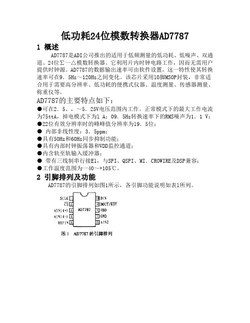
2 引脚排列及功能AD7787的引脚排列如图1所示,各引脚功能说明如表l所列。
3 工作原理AD7787的内部结构功能框图如图2所示。
它内部集成了一个∑一△调制器、一个缓冲器和一个片内数字滤波器。
数字滤波器的主要功能是提供正常模式抑制。
在16.6Hz默认转换速率条件下,它能提供50Hz和60Hz的同步抑制。
AD7787采用内部时钟电路工作,因而无需外接时钟源。
时钟频率以2、4、8因子分频后应用于调制器和滤波器,从而可降低芯片的功耗。
当采用5V单电源供电、缓冲器使能且时钟以最大速率工作时,AD7787的功耗电流最大仅为160,uA。
AD7787有5个片内寄存器:通信寄存器、状态寄存器、模式寄存器、滤波器寄存器和数据寄存器。
所有对AD7787的设置和控制都是通过这些寄存器来实现的。
AD7787具有三种工作模式,分别为:单转换模式、连续转换模式和连续模式。
单转换模式时的转换时序如图3所示。
稳压管型号参数对照表

稳压管型号参数对照表(一)美标稳压二极管型号序号型号稳压值序号型号稳压值序号型号稳压值1 1N4727 3V0 2 1N4728 3V3 3 1N4729 3V6 4 1N4730 3V9 5 1N4731 4V3 6 1N4732 4V7 7 1N4733 5V1 8 1N4734 5V6 9 1N4735 6V2 10 1N4736 6V8 11 1N4737 7V5 12 1N4738 8V2 13 1N4739 9V1 14 1N4740 10V 15 1N4741 11V 16 1N4742 12V 17 1N4743 13V 18 1N4744 15V 19 1N4745 16V 20 1N4746 18V 21 1N4747 20V 22 1N4748 22V 23 1N4749 24V 24 1N4750 27V 25 1N4751 30V 26 1N4752 33V 27 1N4753 36V 28 1N4754 39V 29 1N4755 43V 30 1N4756 47V 31 1N4757 51V(二)有后缀字母A的稳压管型号DZ是稳压管的电器编号,是和1N4148和相近的,其实1N4148就是一个0.6V的稳压管,下面是稳压管上的编号对应的稳压值,有些小的稳压管也会在管体上直接标稳压电压,如5V6就是5.6V的稳压管。
序号型号稳压值序号型号稳压值序号型号稳压值1 1N4728A 3.3 2 1N4729A 3.6 3 1N4730A 3.9 4 1N4731A 4.3 5 1N4732A 4.7 6 1N4733A 5.1 7 1N4734A 5.6 8 1N4735A 6.2 9 1N4736A 6.8 10 1N4737A 7.5 11 1N4738A 8.2 12 1N4739A 9.1 13 1N4740A 10 14 1N4741A 11 15 1N4742A 12 16 1N4743A 13 17 1N4744A 15 18 1N4745A 16 19 1N4746A 18 20 1N4747A 20 21 1N4748A 22 22 1N4749A 24 23 1N4750A 27 24 1N4751A 30 25 1N4752A 33 26 1N4753A 36 27 1N4754A 39 28 1N4755A 43 29 1N4756A 47 30 1N4757A 51 31 1N4758A 56 32 1N4759A 62 33 1N4760A 68 34 1N4761A 75(三)摩托罗拉IN47系列1W稳压管序号型号稳压值序号型号稳压值序号型号稳压值1 IN4728 3.3v2 IN4729 3.6v3 IN4730 3.9v4 IN4731 4.3v5 IN4732 4.7v6 IN4733 5.1v7 IN4734 5.6v 8 IN4735 6.2v 9 IN4736 6.8v10 IN4737 7.5v 11 IN4738 8.2v 12 IN4739 9.1v13 IN4740 10v 14 IN4741 11v 15 IN4742 12v16 IN4743 13v 17 IN4744 15v 18 IN4745 16v19 IN4746 18v 20 IN4747 20v 21 IN4748 22v序号型号稳压值序号型号稳压值序号型号稳压值22 IN4749 24v 23 IN4750 27v 24 IN4751 30v 25 IN4752 33v 26 IN4753 34v 27 IN4754 35v 28 IN4755 36v 29 IN4756 47v 30 IN4757 51v (四)摩托罗拉IN52系列0.5w精密稳压管序号型号稳压值序号型号稳压值序号型号稳压值1 IN5226 3.3v 2 IN5227 3.6v 3 IN5228 3.9v 4 IN5229 4.3v 5 IN5230 4.7v 6 IN5231 5.1v 7 IN5232 5.6v 8 IN5233 6.0v 9 IN5234 6.2v 10 IN5235 6.8v 11 IN5236 7.5v 12 IN5237 8.2v 13 IN5238 8.7v 14 IN5239 9.1v 15 IN5240 10v 16 IN5241 11v 17 IN5242 12v 18 IN5243 13v 19 IN5244 14v 20 IN5245 15v 21 IN5246 16v 22 IN5247 17v 23 IN5248 18v 24 IN5249 19v 25 IN5250 20v 26 IN5251 22v 27 IN5252 24v 28 IN5253 25v 29 IN5254 27v 30 IN5255 28v 31 IN5256 30v 32 IN5257 33vIN57系列序号型号稳压值序号型号稳压值序号型号稳压值1 IN5730 5.6v 2 IN5731 6.2v 3 IN5732 6.8v 4 IN5733 7.5v 5 IN5734 8.2v 6 IN5735 9.1v 7 IN5736 10v 8 IN5737 11v 9 IN5738 12v 10 IN5739 13v 11 IN5740 15v 12 IN5741 16v 13 IN5742 18v 14 IN5743 20v 15 IN5744 22v 16 IN5745 24v 17 IN5746 27v 18 IN5747 30v 19 IN5748 33v 20 IN5749 36v 21 IN5750 39vIN59系列序号型号稳压值序号型号稳压值序号型号稳压值1 IN5985 2.4v 2 IN5986 2.7v 3 IN5987 3v 4 IN5988 3.3v 5 IN5989 3.6v 6 IN5990 3.9v 7 IN5991 4.3v 8 IN5992 4.7v 9 IN5993 5.1v 10 IN5994 5.6v 11 IN5995 6.2v 12 IN5996 6.8v 13 IN5997 7.5v 14 IN5998 8.2v 15 IN5999 9.1v 16 IN6000 10v 17 IN6001 11v 18 IN6002 12v 19 IN6003 13v 20 IN6004 15v 21 IN6005 16v 22 IN6006 18v 23 IN6007 20v 24 IN6008 22v(五)贴片型SOD-123穏压二极管Marking Code SINLOONSMD SOD-123 Zener DiodeType /V oltage / Marking Code序号型号代码标示电压序号型号代码标示电压HZD5221B Z21 2.4V HZD5222B Z22 2.5V HZD5223B Z23 2.7V HZD5224B Z242.8V HZD5225B Z253.0V HZD5226B Z26 3.3V HZD5227B Z273.6V HZD5228B Z28 3.9V HZD5229B Z294.3V HZD5230B Z304.7V HZD5231B Z315.1V HZD5232B Z32 5.6V HZD5233B Z336.0V HZD5234B Z34 6.2V HZD5235B Z35 6.8V HZD5236B Z367.5V HZD5237B Z37 8.2V HZD5238B Z38 8.7V HZD5239B Z39 9.1V HZD5240B Z40 10V HZD5241B Z41 11V HZD5242B Z42 12V HZD5243B Z43 13V HZD5244B Z44 14V HZD5245B Z45 15V。
稳压管大全)
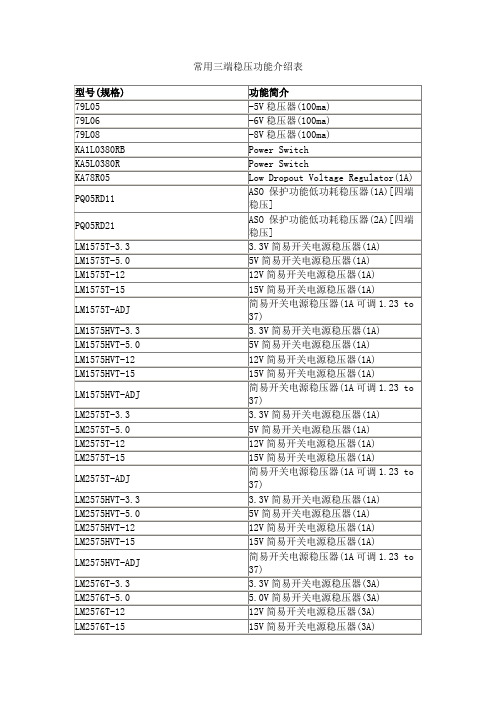
3.3V简易开关电源稳压器(1A)
LM1575T-5.0
5V简易开关电源稳压器(1A)
LM1575T-12
12V简易开关电源稳压器(1A)
LM1575T-15
15V简易开关电源稳压器(1A)
LM1575T-ADJ
简易开关电源稳压器(1A可调1.23 to 37)
LM1575HVT-3.3
LM2575HVT-ADJ
简易开关电源稳压器(1A可调1.23 to 37)
LM2576T-3.3
3.3V简易开关电源稳压器(3A)
LM2576T-5.0
5.0V简易开关电源稳压器(3A)
LM2576T-12
12V简易开关电源稳压器(3A)
LM2576T-15
15V简易开关电源稳压器(3A)
LM2576T-ADJ
79L08
-8V稳压器(100ma)
KA1L0380RB
Power Switch
KA5L0380R
Power Switch
KA78R05
Low Dropout Voltage Regulator(1A)
PQ05RD11
ASO保护功能低功耗稳压器(1A)[四端稳压]
PQ05RD21
ASO保护功能低功耗稳压器(2A)[四端稳压]
型号(规格)
功能简介
兼容型号
CA3130
高输入阻抗运算放大器
Intersil[DATA]
CA3140
高输入阻抗运算放大器
CD4573
四可编程运算放大器
MC14573
ICL7650
斩波稳零放大器
LF347(NS[DATA])
带宽四运算放大器
Z系列中型直流电机

Z系列中型直流电机额定功率55kw - 1600KW额定电压: Normal 400V, 440V, 660V转速: Rated Speed reference防护等级: IP23/IP44绝缘等级: F工作制: S1包装类型:柳条箱/出国熏蒸木箱一、概述本公司开发的Z系列中型直流电动机是采用最新技术设计制造的新产品,该系列电机的机座有六个中心高,从315-560毫米。
本系列电动机的性能、外形安装尺寸及技术要求均符合国家标准(GB)和国际电工委员会标准(IEC),电机各部份机械尺寸,公差符合国际标准化委员会标准(ISO)。
二、使用条件1、本系列电动机可安装在环境条件比较恶劣的场合。
但必须选择正确的冷却方法和防护等级,以保持电机内部的清洁。
2、本系列电动机的冷却空气中应不含有酸、碱等对电机的绝缘和换向性能有损害的气体。
3、本系列电动机如使用干船舶和湿热带地区以及工作环境中有盐雾、潮湿等,应另行协议。
4、本系列电动机的额定功率是指在海拔不超过1000米,环境空气湿度不超过40℃的条件下。
5、本系列电动机的供电电源采用静止整流电源,也可采用直流发电机电源。
6、当电动机采用静止整流电源供电时,整流器的脉波数应不小于6,在额定基速、额定电压和额定负载电流下,电源的峰值纹波因数不超过10%。
三、型号说明本系列电动机的机座采用薄板多角形叠片结构,具有体积小,重量轻等优点。
适用可控硅整流电源,在负载电流的迅速变化下,电动机有良好的换向性能。
整个定于和转子采用无溶剂漆真空压力浸渍处理(VPI),使绕组具有良好的抗潮能力和机械强度,并且绝缘和导热性能优良。
电枢铁心由硅钢片叠装而成,具有良好的导磁性能。
本系列电动机全部采用滚动轴承,不停机加油机构。
本系列电动机的绝缘等级为F级。
本系列电动机的安装型式符合GB997和IEC34—7《电机结构及安装型式代号》。
本系列电动机的防护等级根据GB4942.1和IEC34-5《电机外亮防护分级》标准,外壳防护等级有IP23和IP44两种。
nec八脚继电器规格书

nec八脚继电器规格书摘要:1.NEC 八脚继电器概述2.NEC 八脚继电器规格参数3.NEC 八脚继电器的工作原理4.NEC 八脚继电器的应用领域5.NEC 八脚继电器的优缺点分析正文:EC 八脚继电器概述EC 八脚继电器是一种电子元器件,具有八个引脚,广泛应用于各种自动化设备、通信设备、家电产品等领域。
NEC 公司作为全球知名的电子元器件制造商,其生产的八脚继电器以高品质、稳定性能而受到广泛好评。
本文将对NEC 八脚继电器的规格书进行分析,帮助读者更好地了解这款产品。
EC 八脚继电器规格参数EC 八脚继电器的具体规格参数如下:1.型号:例如,NEC JW-8Z-12V,其中“JW”表示继电器,“8Z”表示八脚继电器,“12V”表示线圈电压为12 伏特。
2.触点容量:表示继电器能够承受的最大电流。
例如,NEC JW-8Z-12V 的触点容量为1A@125VAC。
3.线圈电阻:表示线圈的电阻值,单位为欧姆。
例如,NEC JW-8Z-12V 的线圈电阻为1200 欧姆。
4.动作时间:表示继电器在接收到信号后从静止状态切换到动作状态所需的时间。
例如,NEC JW-8Z-12V 的动作时间为5ms。
5.绝缘电阻:表示继电器的绝缘性能,单位为兆欧姆。
例如,NEC JW-8Z-12V 的绝缘电阻为100MΩ。
EC 八脚继电器的工作原理EC 八脚继电器的工作原理主要基于电磁感应原理。
当线圈通电时,会在继电器内部产生磁场。
磁场的作用下,继电器的触点会发生吸合或断开,从而实现信号的切换。
EC 八脚继电器的应用领域EC 八脚继电器广泛应用于各种自动化设备、通信设备、家电产品等领域,例如:1.自动化设备:如工业机器人、自动化生产线等。
2.通信设备:如电话交换机、光纤传输系统等。
3.家电产品:如电视机、空调、洗衣机等家用电器。
EC 八脚继电器的优缺点分析EC 八脚继电器具有以下优缺点:优点:1.品质稳定:NEC 作为知名品牌,其八脚继电器品质可靠,稳定性能好。
QS7785中文资料
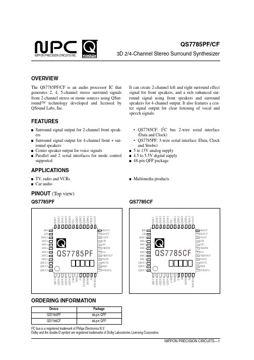
BYP(SDA) 12
ORDERING INFORMATION
Device QS7785PF QS7785CF
Package 48-pin QFP 48-pin QFP
I2C bus is a registered trademark of Philips Electronics N.V. Dolby and the double-D symbol are registered trademarks of Dolby Laboratories Licensing Corporation.
–
SCL
BASS
MUTE
PSAVE
VREFOUT
NC
VREFIN
LPC
CIN
COUT
SLOUT
SROUT
FLOUT
FROUT
QXBC4
QXBC3
QXBC2
QXBC1
VCC
QXAC4
QXAC3
QXAC2
QXAC1
BASC1
QS7785PF/CF
I/O
Description
O QEXPANDER C capacitor 4 I QEXPANDER D capacitor 1 O QEXPANDER D capacitor 2 I QEXPANDER D capacitor 3 O QEXPANDER D capacitor 4 – Ground – 4.5 to 5.5V digital supply I Input mode control (HIGH: parallel, LOW: serial) I Enhancement control (HIGH: high spread, LOW: low spread) I Serial data strobe (not applicable to QS7785CF) I Mono-to-stereo convert select (HIGH: mono to stereo mode, LOW: normal mode) I Center output control (HIGH: center on, LOW: center off) I Bypass control (HIGH: bypass, LOW: Qsurround) I/O Serial data input (also serves as ACK signal output for I2C bus) I Surround speaker control (HIGH: surround speaker on, LOW: off) I Serial clock signal input I Bass boost mode control (HIGH: bass boost on, LOW: bass boost off) I Mute signal control (HIGH: mute on, LOW: mute off) I Power save control (HIGH: power save on, LOW: power save off) O VCC/2 reference voltage output – No connection I VCC/2 reference voltage output (biased internally to VCC/2) I Center output lowpass filter I COUT output signal feedback input for front-channel output O Center signal output O Surround left-channel signal output O Surround right-channel signal output O Front left-channel signal output O Front right-channel signal output O QEXPANDER B capacitor 4 I QEXPANDER B capacitor 3 O QEXPANDER B capacitor 2 I QEXPANDER B capacitor 1 – 5 to 13V DC analog supply O QEXPANDER A capacitor 4 I QEXPANDER A capacitor 3 O QEXPANDER A capacitor 2 I QEXPANDER A capacitor 1 I Bass boost right-channel signal input
MT7885规格书-中文 _Rev1.15
应用
LED球泡灯,日光灯,信号灯,景观灯等 LED舞台灯,蜡烛灯,玉米灯等 其他LED驱动应用及通用恒流源
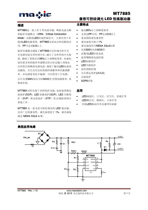
典型应用电路
B7 Vin_ac R3 C1 F1 C12 Rst21 R1 Rst22 Rst1 L1 R4 CO
VLED+ VLED-
D1
MT7885
4 TM 3 VCC 2 OVP 1
D1 Rst21 R1 Rst22
MT7885
4 TM 3 VCC 2 OVP 1
DRAIN DRAIN NC CS
5 6 7 8 Rcs
C2
R2GNDU1源自开路保护的设置要注意几点: 1) 为方便设计,需使电阻由Rst21和Rst22相 等,即Rst21=Rst22,以达到平均分摊采样电压的 作用, 用于过压保护OVP值的设定。 Rst21和Rst22 的取值在150K欧姆~400K欧姆之间。如果需要支 持的母线电压偏低,则电阻Rst21和Rst22取值要 小;反之,则可以大一些,以提高系统效率。 2) 受分压电阻串R1, R2的精度影响, 以及芯 片内部参考电平的精度影响,公式(6)计算得到 的OVP阈值与实际的OVP阈值有一定的误差。准 确的OVP值可以通过调节R2的阻值来达到。OVP 值偏低,应该减小R2阻值;反之,则应加大R2的 阻值。建议R2初值取4.7K欧姆左右,用公式(6) 来确定R1的阻值,然后微调R2来精确确定OVP 值。 3) 建议将开路保护阈值设置在系统最大的
管脚描述
管脚名称 GND OVP VCC TM DRAIN NC CS 管脚号 1 2 3 4 5/6 7 8 芯片地 开路保护设置引脚及线电压采样补偿引脚 芯片电源,内部限压 15.5V 测试引脚,应用时必须悬空。 内部高压功率MOS管漏极 悬空脚 电流采样端,接采样电阻到地 描述
PRS-778-D变压器成套保护装置技术说明书(标准220kV版)V1.10-140612
5.1 装置设备参数定值................................................................................................20 5.2 差动保护定值 .......................................................................................................21 5.3 差动保护控制字 ...................................................................................................21 5.4 高压侧后备保护定值............................................................................................22 5.5 高压侧后备保护控制字........................................................................................23 5.6 中压侧后备保护定值............................................................................................23
本说明书为PRS-778-D装置用于国网220kV电压等级系统主变保护的技术说明书,适用于PRS-778-D V2.01及以上兼容标准220kV软件版本。
欧姆龙继电器型号 文档 (2)
公司是欧姆龙一级代理商,价格优势明显,质量有保证,有大量库存,供货期短。
欢迎新老客户来电查询联系人:1 3 5 2 0 1 1 5 8 9 1 传0 1 0- 8 0 1 1 5 5 5 5转7 5 9 7 1 13F88L-RS173G3IV-PLKEB45P53G3JV-MANUAL3G3JZ-AB0223G3MV-A4075(YES)3G3MZ-A2004-ZV23G3MZ-A2007-ZV23G3MZ-A2015-ZV23G3MZ-A2055-ZV23G3RV-B418K-ZV13G3RV-B422K-ZV13G3RV-B4900-ZV13G3RX-A4220-Z43767-0010 MC374005-3066 UM5-3066C200H-ATT01C200H-BC101-V2C200H-CP114C200H-DA001C200H-DA002C200H-ID218C200H-ID501C200H-NC111C200H-OD501C200H-TS001C200HW-COM01C200HW-COM05-EV1C200HW-DRM21-V1C200HW-NC213C500-CE405CJ1W-OD263CP1W-20EDT1(Q)CP1W-40EDT1CPM1A-20EDT1CPM1A-40CDT-A-V1 CPM2A-20CDR-DCPM2A-20CDT-DCPM2A-30CDR-DCQM1-ID211CQM1-ME04RCQM1H-PLB21CRT1-AD04CS1D-CPU44SCS1H-CPU66HCS1H-CPU67HCS1W-BAT01CS1W-BI033CS1W-CN224CS1W-OC201CS1W-PDC55CS1W-SCU31-V1D4N-212GDRT1-232C2DRT2-AD04E2E-X10D1S DC12-24 2ME3X-DAC21-S 2ME5AZ-C3E5AZ-Q3E5AZ-R3E5CN-Q2HBT AC100-240 (Q)E5CN-R2HBT AC100-240 (Q)E5CN-R2T AC100-240 (Q)E5CZ-Q2 AC100-240E5CZ-R2MT AC100-240E5EZ-C3E6C2-CWZ6C 1024P/R 2M BY OMSG3JA-C425B AC100-240 FOR CHINA G3JA-C430B AC100-240 FOR CHINA G3JA-C437B AC100-240 FOR CHINA G3JA-D420B AC100-240 FOR CHINA G3JA-D425B AC100-240 FOR CHINA G3JA-D432B AC100-240 FOR CHINA G3JA-D451B AC100-240 FOR CHINA G3PB-535B-2N-VD DC12-24H5CN-XCN AC100-240H5F-BMKS2P DC12MKS3P-5 DC48MPT-CN550NS10-TV01B-V2R7A-CNB01S-ZR7A-CNB01SB-ZR7A-CNZ01C-ZR7D-AP04HR7D-AP08HR7D-BP01H-ZR7D-BP02H-ZR7D-BP02HH-ZR7D-BP04H-ZR7D-ZP01HR7D-ZP02HR7M-A40030-S1R7M-A75030-S1R7M-Z10030-S1ZR7M-Z20030-S1ZR88A-CNG01SB-ZR88D-GN01H-ML2-ZR88D-GN02H-ML2-ZR88D-GN04H-ML2-ZR88D-GN08H-ML2-ZR88D-GN10H-ML2-ZR88D-GN15H-ML2-ZR88D-GN20H-ML2-ZR88D-GN50H-ML2-ZR88D-GN75H-ML2-ZR88D-GT50H-ZR88D-GT75H-ZR88D-WN08H-ML2R88D-WN10H-ML2R88M-G10030H-BS2-Z R88M-G10030H-ZR88M-G1K020H-S2-Z R88M-G1K020H-ZR88M-G1K020T-BS2-Z R88M-G1K020T-S2-Z R88M-G1K020T-ZR88M-G1K030H-BS2-Z R88M-G1K030H-S2-Z R88M-G1K030H-ZR88M-G1K030T-S2-Z R88M-G1K520H-BS2-Z R88M-G1K520H-S2-Z R88M-G1K520H-ZR88M-G1K520T-BS2-Z R88M-G1K520T-S2-Z R88M-G1K520T-ZR88M-G1K530H-S2-Z R88M-G1K530T-S2-Z R88M-G20030H-BS2-Z R88M-G20030T-BS2-Z R88M-G20030T-S2-Z R88M-G2K010H-S2-Z R88M-G2K010H-ZR88M-G2K010T-S2-Z R88M-G2K010T-ZR88M-G2K020H-BS2-Z R88M-G2K020H-S2-Z R88M-G2K020H-ZR88M-G2K020T-S2-ZR88M-G2K030H-S2-Z R88M-G2K030T-S2-Z R88M-G3K010H-BS2-Z R88M-G3K010H-S2-Z R88M-G3K010H-ZR88M-G3K010T-S2-Z R88M-G3K020H-BS2-Z R88M-G3K020H-S2-Z R88M-G3K020H-ZR88M-G3K020T-S2-Z R88M-G3K020T-ZR88M-G3K030H-BS2-Z R88M-G3K030H-S2-Z R88M-G3K030H-ZR88M-G40030H-B-ZR88M-G40030H-BS2-Z R88M-G40030H-ZR88M-G40030T-BS2-Z R88M-G40030T-S2-Z R88M-G4K020H-BS2-Z R88M-G4K020H-S2-Z R88M-G4K020T-S2-Z R88M-G4K030H-BS2-Z R88M-G4K030H-S2-Z R88M-G4K510H-BS2-Z R88M-G4K510H-S2-Z R88M-G4K510T-S2-Z R88M-G5K020H-BS2-ZR88M-G5K030H-BS2-ZR88M-G5K030H-S2-ZR88M-G6K010H-BS2-ZR88M-G6K010H-S2-ZR88M-G75030H-BS2-ZR88M-G75030T-BS2-ZR88M-G75030T-S2-ZR88M-G7K515H-BS2-ZR88M-G7K515H-S2-ZR88M-G7K515T-S2-ZR88M-G90010T-S2-ZR88M-GP10030H-ZR88M-GP40030H-ZR88M-W10030T-S1SH-001-01MSH-001-03MSH-001-05MSH-001-10MV400-W23 3MV400-W24 3MWLCA32-41ZR-RX20A-CHROZR-RX40A-CHROZR-XRB1ZR-XRE1我公司是欧姆龙一级代理商,价格优势明显,质量有保证,有大量库存,供货期短。
直流电源设备性能详细说明及主要参数表

设备性能详细说明及主要参数表1)适用范围本系统适用于新校区高低压配电系统设备,可作为直流操作、继电保护、信号回路、事故照明等负荷的直流电源,是一种理想的直流电源成套设备。
2)选型原则2.1公司直流设备已通过省级以上形式试验报告(型号HZ-GZDW-220/20/100)。
2.2我厂直流设备制造已通过ISO9001:2000系列认证。
符合国际EMC安全规定1、IEC61000-4-2(ESD): 抗静电能力2、IEC61000-4-3(RS): 抗辐射干扰能力3、IEC61000-4-4(EFT): 抗电源脉冲干扰能力4、IEC61000-4-5(Surge): 防雷击/突波能力产品应符合下列标准要求5、DL/T 781-1995 电力用高频开关整流模块6、GB/T 3859.1-1993 半导体变流器基本要求的规定7、GB/T 3859.2-1993 半导体变流器应用导则8、DL/T 459-2000 电力系统直流电源柜订技术条件9、DL/T 637-1997 阀控式铅酸蓄电池订技术条件10、GB/T 17626-1998电磁兼容试验和测量技术11、GB50171-1992 电气装置安装工程盘、柜及二次回路接线施工及验收标准12、GB50172-1992 电气装置安装蓄电池施工及验收标准3)环境条件1、海拔高度: 不超过2000m;2、环境温度: -10℃~+45℃;3、相对湿度: ≤90%(在25℃室温时) ;4、地震烈度: 不超过8度;5、设备限在室内工作,且通风良好;6、室内应无腐蚀金属和破坏绝缘的有害气体;7、安装垂直倾斜度: 不超过5°;8、微控制器抗噪声: 1000V 1μs脉冲1分钟;9、无强电磁场干扰与剧烈振动。
4)直流系统工作原理两路市电经过切换输入一路(或一路市电),给各个充电模块供电。
充电模块将输入三相交流电转换为直流电,给蓄电池充电,同时给合闸母线负载供电,另外合闸母线通过降压装置给控制母线供电。
EIC7785-8中文资料

7.70-8.50 GHz 8-Watt Internally-Matched Power FETFEATURES•7.70 – 8.50 GHz Bandwidth•Input/Output Impedance Matched to 50 Ohms•+39.5 dBm Output Power at 1dB Compression•8.5 dB Power Gain at 1dB Compression•34% Power Added Efficiency•-46 dBc IM3 at Po = 28.5 dBm SCL•Hermetic Metal Flange Package•100% Tested for DC, RF, and R THDESCRIPTIONThe EIC7785-8 is a high power, highly linear,single stage MFET amplifier in a flange mountpackage. This amplifier features Excelics’ uniqueMESFET transistor technology.ELECTRICAL CHARACTERISTICS (T a = 25°C)SYMBOL PARAMETERS/TESTCONDITIONS1 MINTYPMAXUNITSP1dB Output Power at 1dB Compression f = 7.70-8.50GHzV DS = 10 V, I DSQ≈ 2200mA38.5 39.5 dBmG1dB Gain at 1dB Compression f = 7.70-8.50GHzV DS = 10 V, I DSQ≈ 2200mA7.5 8.5 dB∆G Gain Flatness f = 7.70-8.50GHzV DS = 10 V, I DSQ≈ 2200mA±0.6dBPAE Power Added Efficiency at 1dB CompressionV DS = 10 V, I DSQ≈ 2200mA f = 7.70-8.50GHz34 %Id1dB Drain Current at 1dB Compression f = 7.70-8.50GHz 2200 2600 mAIM3 Output 3rd Order Intermodulation Distortion∆f = 10 MHz 2-Tone Test; Pout = 28.5 dBm S.C.L2V DS = 10 V, I DSQ≈ 65% IDSS f = 8.50 GHz-43 -46 dBcI DSS Saturated Drain Current V DS = 3 V, V GS = 0 V 4000 4500 mAV P Pinch-off Voltage V DS = 3 V, I DS = 40 mA -2.5 -4.0 V R TH Thermal Resistance3 3.5 4.0 o C/W Notes:1. Tested with 100 Ohm gate resistor.2. S.C.L. = Single Carrier Level.3. Overall Rth depends on case mounting.ABSOLUTE MAXIMUM RATINGS FOR CONTINUOUS OPERATION 1,2SYMBOL CHARACTERISTIC VALUE V DS Drain to Source Voltage 10 V V GS Gate to Source Voltage -4.5 V I DS Drain CurrentIDSS I GSF Forward Gate Current 80 mAP IN Input Power@ 3dB compressionP TTotal Power Dissipation32 W T CH Channel Temperature 150°C T STG Storage Temperature-65/+150°CNotes:1. Operating the device beyond any of the above ratings may result in permanent damage or reduction of MTTF.2. Bias conditions must also satisfy the following equation P T < (T CH –T PKG )/R TH ; where T PKG = temperature of package, andP T = (V DS * I DS ) – (P OUT – P IN ).PERFORMANCE DATATypical S-Parameters (T= 25°C, 50Ω system, de-embedded to edge of package) V DS = 10 V, I DSQ ≈ 2200mAFREQ --- S11 --- --- S21 ------ S12 --- --- S22 ---(GHz)MAG ANGMAG ANGMAG ANGMAG ANG7.5 0.5659 -169.06 2.653 -99.16 0.1125 -153.47 0.5992 27.257.6 0.5159 177.44 2.7741 -111.83 0.1208 -165.72 0.5788 16.12 7.7 0.4615 161.8 2.9098 -125.33 0.127 -178.82 0.5468 4.26 7.8 0.3953 143.64 3.0355 -139.33 0.1344 167.39 0.5069 -8.197.9 0.3292 123.15 3.1442 -153.81 0.1405 153.05 0.4486 -22.61 8 0.2633 96.94 3.2247 -169.11 0.1461 138.07 0.3863 -39.28 8.1 0.2092 62.41 3.2539 174.99 0.1485 122.37 0.3151 -59.64 8.2 0.1858 17.93 3.2534 158.73 0.1502 107.25 0.2486 -87.21 8.3 0.2058 -25.56 3.1658 142.39 0.1484 91.76 0.2147 -122.78 8.4 0.2616 -60.84 3.0487 126.26 0.143 76.38 0.2226 -161.62 8.5 0.3184 -87.64 2.8796 110.62 0.1378 60.95 0.27 167.25 8.6 0.3806 -108.87 2.6767 95.4 0.1301 46.15 0.3349 145.24 8.7 0.4359 -127.56 2.4875 81.13 0.1224 30.86 0.3959 128.51Power De-rating Curve and IM3 DefinitionSafe OperatingRegion Potentially UnsafeOperating RegionTypical Power Data (V DS = 10 V, I DSQ = 2200 mA) Typical IM3 Data (V DS = 10 V, I DSQ≈ 65% IDSS)2. Exact test conditions are specified in “Electrical Characteristics” table.。
富士通 FLM7785-4F 说明书

Fujitsu recommends the following conditions for the reliable operation of GaAs FETs:1. The drain-source operating voltage (V DS ) should not exceed 10 volts.2. The forward and reverse gate currents should not exceed 16.0 and -2.2 mA respectively with gate resistance of 100Ω.G.C.P.: Gain Compression Point, S.C.L.: Single Carrier LevelDESCRIPTIONThe FLM7785-4F is a power GaAs FET that is internally matched for standard communication bands to provide optimum power and gain in a 50 ohm system.Eudyna’s stringent Quality Assurance Program assures the highest reliability and consistent performance.FEATURES• High Output Power:P 1dB = 36.5dBm (Typ.)• High Gain:G 1dB = 8.5dB (Typ.)• High PAE:ηadd = 35% (Typ.)• Low IM 3= -46dBc@Po = 25.5dBm • Broad Band:7.7 ~ 8.5GHz• Impedance Matched Zin/Zout = 50Ω• Hermetically SealedPOWER DERATING CURVE122430186050100150200Case Temperature (°C)T o t a l P o w e r D i s s i p a t i o n (W)OUTPUT POWER & IM 3 vs. INPUT POWERV DS =10V f 1= 8.5 GHz f 2 = 8.51 GHz 2-tone test121416182022Input Power (S.C.L.) (dBm)S.C.L.: Single Carrier Level21232527293133-50-40-30-20-10O u t p u t P o w e r (S .C .L .) (d B m )IM 3P outI M 3 (d B c )OUTPUT POWER vs. FREQUENCYPin=28.5dBm26.5dBm24.5dBm22.5dBm7.97.78.18.38.5Frequency (GHz)343536373833O u t p u t P o w e r (d B m )V DS =10V P1dBV DS =10V f = 8.1 GHzOUTPUT POWER vs. INPUT POWER18202224262830Input Power (dBm)343638323028304515O u t p u t P o w e r (d B m )ηaddP outηa d d (%)S-PARAMETERSV DS = 10V , I DS = 1100mAFREQUENCY S11S21S12S22(MHZ)MAG ANG MAG ANG MAG ANG MAG ANG 7500.711120.0 3.482-74.8.025-92.7.478147.97600.694109.7 3.441-86.9.031-113.4.490133.67700.67299.8 3.396-98.7.037-131.2.507120.77800.64890.0 3.354-110.3.043-143.4.525109.97900.62180.2 3.331-121.7.049-157.1.53599.88000.59170.2 3.319-133.1.055-170.0.54190.78100.55759.3 3.344-144.8.061178.8.54282.68200.51647.3 3.377-156.5.067166.5.53974.98300.47033.5 3.444-168.7.074154.9.52567.58400.41416.0 3.540178.2.080141.7.49659.78500.356-7.7 3.625163.9.089128.6.44952.98600.308-40.8 3.704148.3.097113.5.38046.98700.307-83.13.723131.3.10197.4.28243.10-j50S 0°S 21S 12Eudyna Devices Inc. products contain gallium arsenide(GaAs) which can be hazardous to the human body and the environment. For safety, observe the following procedures:CAUTION• Do not put this product into the mouth.• Do not alter the form of this product into a gas, powder, or liquidthrough burning, crushing, or chemical processing as these by-products are dangerous to the human body if inhaled, ingested, or swallowed.• Observe government laws and company regulations when discarding this product. This product must be discarded in accordance with methods specified by applicable hazardous waste procedures.For further information please contact:Eudyna Devices USA Inc.2355 Zanker Rd.San Jose, CA 95131-1138, U.S.A.TEL:(408) 232-9500FAX:(408) 428-9111Eudyna Devices Europe Ltd.Network House Norreys DriveMaidenhead, Berkshire SL6 4FJ United KingdomTEL:+44 (0) 1628 504800FAX:+44 (0) 1628 504888Eudyna Devices Asia Pte Ltd.Hong Kong BranchRm.1101, Ocean Centre, 5 Canton Rd.Tsim Sha Tsui, Kowloon, Hong Kong TEL:+852-2377-0227FAX:+852-2377-3921Eudyna Devices Inc.Sales Division1, Kanai-cho, Sakae-kuY okohama, 244-0845, Japan TEL:+81-45-853-8156FAX:+81-45-853-8170Eudyna Devices Inc.reserves the right to change products and specifications without notice.The information does not convey any license under rights of Eudyna Devices Inc.or others.©2004 Eudyna Devices USA Inc.Printed in U.S.A.。
Mitsubishi Electric 工业机器人 MELFA RV-8CRL 产品介绍说明书

FACTORY AUTOMATIONMITSUBISHI ELECTRICINDUSTRIAL ROBOTMELFA RV-8CRLAllied Automation 800-214-0322Pursuing practical performanceUses an HK motor, the latest servomotor from Mitsubishi Electric. This allows improved torque characteristics, accuracy, and responsiveness while substantially reducing the size and weight. This adds up to much better robot performance and greater compactness.Continuous operation performanceLighter weight and improved heat release translate to improved continuous operation performance.Beltless coaxial drive mechanismA coaxial drive mechanism without belts is used for transmission to each axis (excluding the J4 and J5 axes).Simplification of the structure has improved transmission efficiency and reliability while also improving the ease of maintenance.No backup batteryThe use of the new HK motor eliminates the need for a battery to back up the robot’s internal encoder.This eliminates the cost and effort of regularreplacement as well as the risk of losing origin coordinates due to battery failure.A signal wire and air piping that can be used for gripper control, etc., are built in from the base to the forearm. Both ends of the signal wire haveuniversal D-sub connectors for use in various applications.Highest-in-class load capacityFeaturing a highest-in-class maximum load capacity of 8 kg, these robots boast a lighter-weight structure and reduced unit weight thanks to their simplified drive system and optimized arm structure, resulting in enhanced load capacity.Largest-in-class effective working areaOffers highest-in-class maximum reach radius of 931 mm. The use of a no-offset lower arm structure eliminating the J2-axis joint offset minimizes the interference region in the minimum turning radius and provides the largest-in-class effective working area.Standard IP65 supportComes standard with environmental resistance features allowing installation in plants and equipment where dust or oil mist is present.Can be used in oil mist environmentsJ6-axis motorJ3-axismotor J2-axismotorJ1-axismotor Slim & Compact Robot Offering a High Level of Utility and DesignSlim & compactA smooth, curved design complements the slim arm and compact joints. The external design is marked by minimalist, functional design.*Installation pitch:□160 mm (same as RV-4FR and 20% less than RV-7FR)Protrusionless structureIn addition to a slim, compact exterior and small robot base, its structure features minimal protrusions to the front, back, and sides, resulting in reduced interference with surroundings when the robot operates. This makes it suited to integration with automation cells and manufacturing equipment.1High-performance Controller Makes MELFA More IntelligentSafety monitoring functionWe will prepare a safety function compliant with international standards that simplifies risk assessments.Safety I/OExtends redundant safety I/O to 8 inputs and 4 outputs. Enablesdevelopment of various safety systems.Safety logic editingSimplifies development and operation of safety systems with safety logic editing.●Program editing and debugging ●Simulation function ●3D viewer●Monitoring function●Melfa RXM.ocx communication middlewareTrackingRobot tracks workpiece on conveyor, allowing transfer, alignment, and assembly without stopping conveyor.Additional axis controlBuild user mechanism controlling additional axes simultaneously with robot such as robot drive axis or turntable or separate from robot such as loader or positioning device. Control up to 8 axes. Our MELSERVO (MR-J4-B)servomotor can be used with additional axes.Robot mechanism thermal compensation functionMeasures the temperature of the robot arm and automatically corrects errors arising from thermal expansion of the arm.Callibration assistance functionAutomated calibration translates to simplification of installation of two-dimensional vision sensor and improvement of operational accuracy.Coordinated control of additional axesLinks robot and travel base for high-accuracy processing and assembly at specific speed.Also supports optional MELFA SmartPlusfunctional enhancement *1Comes standard with tracking and additional axis control PC software supporting everything from robot system designto installation, debugging, operation, and maintenance●Vision sensor configuration tool allows easy calibration of robot and camera ●Easy connection of robot and camera via Ethernet ●Easy control via robot program vision control commandSimultaneous controlmechanismsMechanism 1Mechanism 2Mechanism 3Up to 3Additional axesVision sensorSupports multiple conveyors simultaneously (up to 8)*1: Coming soonRobot controllerRobotLaser scannerTeaching boxRT ToolBox3Emergency stopArea sensorLamp2SpecificationsMechanical interfaceInternal wiring/pipingWiring/pipingInstallation dimensionsExternal dimensions/operating rangeMain Specifications15-pin D-sub AWG#24 (0.2mm ) ×15φ6 air joint (2)φ6 hose (2)Black Green Red Brown Yellow OrangeBlue Purple Gray Pink Light blue (Black)/Yellow (Black)/White (Black)/Blue 123456789101112131415123456789101112131415①②Baseφ6 air joint ①Tool wiring connector (15-pin D-sub)Tool wiring connector (15-pin D-sub)φ6 air joint ②Air pipe (2)φ6 air joint ①BaseUpper armForearmView A15-pin D-subForearmφ6 air joint ②Tool wiring (15)Tool wiring connectorRz25R z 25(Installation reference plane)(I n s t a l l a t i o n r e f e r e n c e p l a n e )1908080(160)978080(160)9797φ40h 8φ20H 7D6P .C.D .φ31.545°4-M5 thread depth 8φ5H7D84-φ9 installation hole*1: The wall mounting specifications are special specifications that restrict the operating range of the J1 axis.*2: “Maximum load capacity” is the maximum weight that can be loaded under the limitation of a mechanical interface having a downward attitude (within ±10° of the vertical position).View BP point operating areaP pointR 930.5-170°+170°R 219.315071R 150930.5930.51320.5244.4634.4930.585470390450100R 930.5+110°-110°Control point (R point)P point operating areaP point Downward limit of wristR 219.3102028020A71BWrist's downward singularity boundarySpace for the cable connectionMinimum: 310250256White 3External dimensions*2: Power supply voltage variability is within 10%.*3: Power capacity is recommended value.Note that power capacity does not include making current when turning on. Power capacity is an estimate.*4: Grounding work is to be performed by the customer.*5: Recommended USB cable (USB Type A, USB Mini-B Type): MR-J3USBCBL3M (Mitsubishi Electric), GT09-C30USB-5P (Mitsubishi Electric System & Service)*6: Mode select switch is to be provided by the customer.Controller specificationsStand-alone robot controllerRobot controller can be used for centralized control.430(30)30(3.5)37099.59642534045(40)(45)CR800-D4System configurationParallelinput-output interfaceinput-output unitExternal input-output cableCC-Link <Standard devices>GOT Pulse encoderServo Network R56TBR32TBsupport(SmartPlus)Machine cableController protection box<Functional options>Force sensor set MELFA-3D Vision⑨⑥RT ToolBox3 mini RT ToolBox3RT ToolBox3 Pro⑭②Encoder interfaceRobotRobot controller*1: Coming soon5OptionsController optionsFunctional optionsExpanded software functions*1: Coming soon6L (NA )09102ENG-BAll trademarks acknowledged.Printed December 2019HEAD OFFICE: TOKYO BLDG., 2-7-3 MARUNOUCHI,CHIYODA-KU, TOKYO 100-8310, JAPANMitsubishi Electric Corporation Nagoya Works is a factory certified for ISO 14001 (standards for environmental management systems) and ISO 9001(standards forquality assurance management systems)Global Partner. Local Friend.Allied Automation 800-214-0322。
- 1、下载文档前请自行甄别文档内容的完整性,平台不提供额外的编辑、内容补充、找答案等附加服务。
- 2、"仅部分预览"的文档,不可在线预览部分如存在完整性等问题,可反馈申请退款(可完整预览的文档不适用该条件!)。
- 3、如文档侵犯您的权益,请联系客服反馈,我们会尽快为您处理(人工客服工作时间:9:00-18:30)。
*3, 4
ηadd
(%) VDS
TEST CONDITIONS IDS (RF OFF) (V) 10 10 10 10 10 10 (A) 1.6 1.6 1.6 1.6 1.6 1.6 FREQUENCY IM3 TEST BAND (GHz) 3.6 to 4.2 4.4 to 5.0 5.9 to 6.45 6.4 to 7.2 7.1 to 7.7 7.7 to 8.5 FREQ. (GHz) *5 4.2 5.0 6.45 7.2 7.7 8.5
*4
GL (dB)
IDS (A)
*2
GL (dB)
*3, 4
η add
(%) VDS
TEST CONDITIONS IDS (RF OFF) (V) 10 10 10 10 10 10 (A) 0.8 0.8 0.8 0.8 0.8 0.8 FREQUENCY IM3 TEST BAND (GHz) 3.6 to 4.2 4.4 to 5.0 5.9 to 6.45 6.4 to 7.2 7.1 to 7.7 7.7 to 8.5 FREQ. (GHz) *5 4.2 5.0 6.45 7.2 7.7 8.5
MAXIMUM OPERATING LIMITS
Rg max. (Ω) 200 VDS max. (V) 10
Rg max is the maximum series resistance between the gate supply and the FET gate.
3
元器件交易网
+0.1 0.1–0.05
5.0MAX.
0.2MAX.
2.6±0.2
1.6
4.4 to 5.0 5.9 to 6.45 6.4 to 7.2 7.1 to 7.7 7.7 to 8.5
12.0
FEATURES
• Internally matched to 50 Ω • High power output • High linear gain • High reliability • Low distortion
MIN. TYP. MIN. TYP. TYP. MAX. MAX. TYP. MAX. TYP. NEZ3642-4D 35.5 36.5 36.5 36.5 36.5 36.5 36.5 10.0 9.5 9.0 8.0 7.5 7.0 11.0 10.5 10.0 9.0 8.5 8.0 1.2 1.2 1.2 1.2 1.2 1.2 1.5 1.5 1.5 1.5 1.5 1.5 1.0 1.0 1.0 1.0 1.0 1.0 – 45 – 42 – 45 – 42 – 45 – 42 – 45 – 42 – 45 – 42 – 45 – 42 43 40 37 35 33 33
Notes *1 Output power at 1dB gain compression point *2 IDS values are specified at P1dB point. *3 Gain flatness *4 Applies to – 8DD option only *5 IM3 test conditions: f = 10 MHz, 2 tones test, PO = 29dBm (single carrier level)
Pout (dBm) ID (A) 2 35
OUTPUT POWER vs. INPUT POWER
Test Conditions: Freq = 3.9 (GHz), VDS = 10.0 (V), IDS = 0.8 (A), Pout: Pin = 27.0 (dBm), GL: Pin = 20.0 (dBm), Rg = 200 (Ω)
2
元器件交易网
4W/8W C-BAND Power-GaAs FET NEZ Series
S
4W PERFORMANCE SPECIFICATIONS (TA = 25 ˚C, Z
P1dB PART NUMBER (dBm)
*1
= ZL = 50 Ω)
IM3 (dBc)
PACKAGE DIMENSIONS (unit: mm)
0.5±0.1
2.5MIN.
C1.5 4PLACES SOURCE R1.6 2PLACES
GATE
2.4
12.9±0.2
3.2
6.45±0.05
DRAIN 17.0±0.2 21.0±0.3 10.7
2.5MIN.
SELECTION CHART
元器件交易网
PRELIMINARY DATA SHEET
GaAs MES FET
4W/8W C-BAND POWER GaAs FET NEZ Series
4W/8W C-BAND POWER GaAs FET N-CHANNEL GaAs MES FET
DESCRIPTION
NEZ PART NUMBER NEZ3642-4D, 8D, 8DD NEZ4450-4D, 4DD/8D, 8DD NEZ5964-4D, 4DD/8D, 8DD NEZ6472-4D, 4DD/8D, 8DD NEZ7177-4D, 4DD/8D, 8DD NEZ7785-4D, 4DD/8D, 8DD FREQUENCY BAND (GHz) 3.6 to 4.2
MIN. TYP. MIN. TYP. TYP. MAX. MAX. TYP. MAX. TYP. NEZ3642-8D, 8DD 38.5 NEZ4450-8D, 8DD 38.5 NEZ5964-8D, 8DD 38.5 NEZ6472-8D, 8DD 38.5 NEZ7177-8D, 8DD 38.5 NEZ7785-8D, 8DD 38.5 39.5 39.5 39.5 39.5 39.5 39.5 10.0 9.5 8.5 7.5 7.0 6.5 11.0 10.5 9.5 8.5 8.0 7.5 2.4 2.4 2.4 2.4 2.4 2.4 3.0 3.0 3.0 3.0 3.0 3.0 1.0 1.0 1.0 1.0 1.0 1.0 – 45 – 42 – 45 – 42 – 45 – 42 – 45 – 42 – 45 – 42 – 45 – 42 40 37 35 32 30 30
Document No. P10981EJ1V0DS00 (1st edition) Date Published June 1996 P Printed in Japan
©
1996
元器件交易网
4W/8W C-BAND POWER-GaAs FET NEZ Series
4W/8W C-BAND POWER-GaAs FET NEZ Series
= ZL = 50 Ω)
IM3 (dBc)
*4
8W PERFORMANCE SPECIFICATIONS (TA = 25 ˚C, Z
P1dB PART NUMBER (dBm)
*1
S
GL (dB)
IDS (A)
*2
GL (dB)
CHARACTERISTIC
SYMBOL
UNIT
*TC = 25 ˚C
ELECTRICAL CHARACTERISTICS (TA = 25 ˚C)
CHARACTERISTIC Saturated Drain Current SYMBOL IDSS Part No. NEZ-4D NEZ-8D, 8DD Pinch-off Voltage VP NEZ-4D, 4DD NEZ-8D, 8DD Trans-Conductance gm NEZ-4D, 4DD NEZ-8D, 8DD Gate to Drain Voltage BVGD0 NEZ-4D, 4DD NEZ-8D, 8DD Thermal Resistance Rth NEZ-4D, 4DD NEZ-8D, 8DD MIN. 1.0 2.0 – 3.5 – 3.5 — — 20 20 — — TYP. 2.3 4.5 – 2.0 – 2.0 1300 2600 22 22 5.0 2.5 MAX. 3.5 7.0 – 0.5 – 0.5 — — — — 6.0 3.0 ˚C/W V mS V VDS = 2.5 V, IDS = 15 mA VDS = 2.5 V, IDS = 30 mA VDS = 2.5 V, IDS = 1 A VDS = 2.5 V, IDS = 2 A IGD = 15 mA IGD = 30 mA Channel to Case UNIT A TEST CONDITIONS VDS = 2.5 V, VGS = 0 V
ABSOLUTE MAXIMUM RATINGS (TA = 25 ˚C)
RATINGS NEZ-4D, 4DD Drain to Source Voltage Gate to Source Voltage Gate to Drain Voltage Drain Current Gate Current Total Power Dissipation Channel Temperature Storage Temperature VDS VGS VGD ID IG P T* Tch Tstg 15 – 12 – 18 4.5 25 25 175 – 65 to + 175 NEZ-8D, 8DD 15 –12 – 18 9.0 50 50 175 – 65 to + 175 V V V A mA W ˚C ˚C
