有用的图像代码
genimage3用法 -回复

genimage3用法-回复genimage3是一个功能强大的图像生成工具,可用于生成各种类型的图像,包括人物、场景、动物等。
它具有简单易用的特点,使用户只需提供相关参数,即可生成满足要求的图像。
在本文中,将一步一步回答如何使用genimage3这一工具。
首先,我们需要安装genimage3。
可以通过在终端或命令提示符中运行以下命令来安装genimage3:`pip install genimage3`安装完成后,我们可以开始使用genimage3来生成图像。
第一步,我们需要导入genimage3库,并创建一个空的图像对象。
代码如下:pythonimport genimage3 as giimage = gi.GenImage()第二步,我们需要设置图像的尺寸和背景颜色。
可以使用`set_size()`函数设置图像的尺寸,并使用`set_background_color()`函数设置背景颜色。
例如,我们将图像的尺寸设置为500x500像素,并将背景颜色设置为白色:pythonimage.set_size(500, 500)image.set_background_color("white")第三步,我们可以开始添加图像的内容。
genimage3提供了一系列的函数来添加不同类型的内容,如矩形、圆形、文本等。
以下是一些示例代码:添加矩形:pythonimage.add_rectangle(position=(100, 100), size=(200, 200),color="red")添加圆形:pythonimage.add_circle(center=(250, 250), radius=100, color="blue")添加文本:pythonimage.add_text(text="Hello, GenImage3!", position=(50, 50), color="black", font_size=20)除了这些基本的形状和文本,genimage3还提供了许多其他功能,如添加图片、改变颜色、旋转和放大缩小等。
python图形绘制源代码

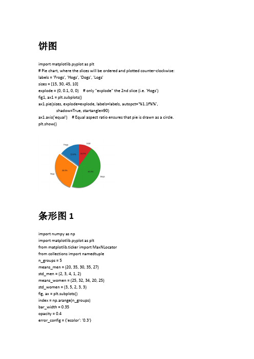
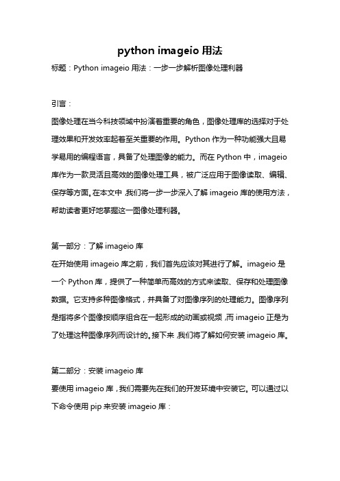
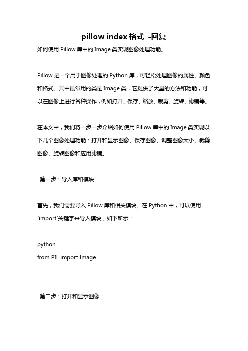
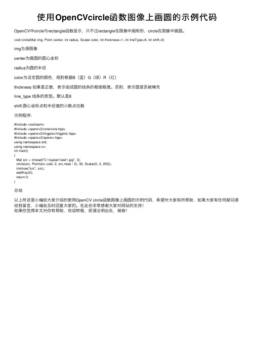
饼图import matplotlib.pyplot as plt# Pie chart, where the slices will be ordered and plotted counter-clockwise: labels = 'Frogs', 'Hogs', 'Dogs', 'Logs'sizes = [15, 30, 45, 10]explode = (0, 0.1, 0, 0) # only "explode" the 2nd slice (i.e. 'Hogs')fig1, ax1 = plt.subplots()ax1.pie(sizes, explode=explode, labels=labels, autopct='%1.1f%%',shadow=True, startangle=90)ax1.axis('equal') # Equal aspect ratio ensures that pie is drawn as a circle. plt.show()条形图1import numpy as npimport matplotlib.pyplot as pltfrom matplotlib.ticker import MaxNLocatorfrom collections import namedtuplen_groups = 5means_men = (20, 35, 30, 35, 27)std_men = (2, 3, 4, 1, 2)means_women = (25, 32, 34, 20, 25)std_women = (3, 5, 2, 3, 3)fig, ax = plt.subplots()index = np.arange(n_groups)bar_width = 0.35opacity = 0.4error_config = {'ecolor': '0.3'}rects1 = ax.bar(index, means_men, bar_width,alpha=opacity, color='b',yerr=std_men, error_kw=error_config,label='Men')rects2 = ax.bar(index + bar_width, means_women, bar_width,alpha=opacity, color='r',yerr=std_women, error_kw=error_config,label='Women')ax.set_xlabel('Group')ax.set_ylabel('Scores')ax.set_title('Scores by group and gender')ax.set_xticks(index + bar_width / 2)ax.set_xticklabels(('A', 'B', 'C', 'D', 'E'))ax.legend()fig.tight_layout()plt.show()表格图import numpy as npimport matplotlib.pyplot as pltdata = [[ 66386, 174296, 75131, 577908, 32015],[ 58230, 381139, 78045, 99308, 160454],[ 89135, 80552, 152558, 497981, 603535],[ 78415, 81858, 150656, 193263, 69638],[139361, 331509, 343164, 781380, 52269]] columns = ('Freeze', 'Wind', 'Flood', 'Quake', 'Hail')rows = ['%d year' % x for x in (100, 50, 20, 10, 5)]values = np.arange(0, 2500, 500)value_increment = 1000# Get some pastel shades for the colorscolors = plt.cm.BuPu(np.linspace(0, 0.5, len(rows)))n_rows = len(data)index = np.arange(len(columns)) + 0.3bar_width = 0.4# Initialize the vertical-offset for the stacked bar chart.y_offset = np.zeros(len(columns))# Plot bars and create text labels for the tablecell_text = []for row in range(n_rows):plt.bar(index, data[row], bar_width, bottom=y_offset, color=colors[row]) y_offset = y_offset + data[row]cell_text.append(['%1.1f' % (x / 1000.0) for x in y_offset])# Reverse colors and text labels to display the last value at the top.colors = colors[::-1]cell_text.reverse()# Add a table at the bottom of the axesthe_table = plt.table(cellText=cell_text,rowLabels=rows,rowColours=colors,colLabels=columns,loc='bottom')# Adjust layout to make room for the table:plt.subplots_adjust(left=0.2, bottom=0.2)plt.ylabel("Loss in ${0}'s".format(value_increment))plt.yticks(values * value_increment, ['%d' % val for val in values])plt.xticks([])plt.title('Loss by Disaster')plt.show()散点图import numpy as npimport matplotlib.pyplot as pltimport matplotlib.cbook as cbook# Load a numpy record array from yahoo csv data with fields date, open, close, # volume, adj_close from the mpl-data/example directory. The record array# stores the date as an np.datetime64 with a day unit ('D') in the date column. with cbook.get_sample_data('goog.npz') as datafile:price_data = np.load(datafile)['price_data'].view(np.recarray)price_data = price_data[-250:] # get the most recent 250 trading daysdelta1 = np.diff(price_data.adj_close) / price_data.adj_close[:-1]# Marker size in units of points^2volume = (15 * price_data.volume[:-2] / price_data.volume[0])**2close = 0.003 * price_data.close[:-2] / 0.003 * price_data.open[:-2]fig, ax = plt.subplots()ax.scatter(delta1[:-1], delta1[1:], c=close, s=volume, alpha=0.5)ax.set_xlabel(r'$\Delta_i$', fontsize=15)ax.set_ylabel(r'$\Delta_{i+1}$', fontsize=15)ax.set_title('Volume and percent change')ax.grid(True)fig.tight_layout()plt.show()平滑图import numpy as npimport matplotlib.pyplot as pltfrom matplotlib.widgets import Slider, Button, RadioButtonsfig, ax = plt.subplots()plt.subplots_adjust(left=0.25, bottom=0.25)t = np.arange(0.0, 1.0, 0.001)a0 = 5f0 = 3delta_f = 5.0s = a0*np.sin(2*np.pi*f0*t)l, = plt.plot(t, s, lw=2, color='red')plt.axis([0, 1, -10, 10])axcolor = 'lightgoldenrodyellow'axfreq = plt.axes([0.25, 0.1, 0.65, 0.03], facecolor=axcolor) axamp = plt.axes([0.25, 0.15, 0.65, 0.03], facecolor=axcolor)sfreq = Slider(axfreq, 'Freq', 0.1, 30.0, valinit=f0, valstep=delta_f) samp = Slider(axamp, 'Amp', 0.1, 10.0, valinit=a0)def update(val):amp = samp.valfreq = sfreq.vall.set_ydata(amp*np.sin(2*np.pi*freq*t))fig.canvas.draw_idle()sfreq.on_changed(update)samp.on_changed(update)resetax = plt.axes([0.8, 0.025, 0.1, 0.04])button = Button(resetax, 'Reset', color=axcolor, hovercolor='0.975')def reset(event):sfreq.reset()samp.reset()button.on_clicked(reset)rax = plt.axes([0.025, 0.5, 0.15, 0.15], facecolor=axcolor)radio = RadioButtons(rax, ('red', 'blue', 'green'), active=0)def colorfunc(label):l.set_color(label)fig.canvas.draw_idle()radio.on_clicked(colorfunc)plt.show()数据打钩标签图import datetimeimport numpy as npimport matplotlib.pyplot as pltimport matplotlib.dates as mdatesimport matplotlib.cbook as cbookyears = mdates.YearLocator() # every yearmonths = mdates.MonthLocator() # every monthyearsFmt = mdates.DateFormatter('%Y')# Load a numpy record array from yahoo csv data with fields date, open, close, # volume, adj_close from the mpl-data/example directory. The record array# stores the date as an np.datetime64 with a day unit ('D') in the date column. with cbook.get_sample_data('goog.npz') as datafile:r = np.load(datafile)['price_data'].view(np.recarray)fig, ax = plt.subplots()ax.plot(r.date, r.adj_close)# format the ticksax.xaxis.set_major_locator(years)ax.xaxis.set_major_formatter(yearsFmt)ax.xaxis.set_minor_locator(months)# round to nearest years...datemin = np.datetime64(r.date[0], 'Y')datemax = np.datetime64(r.date[-1], 'Y') + np.timedelta64(1, 'Y')ax.set_xlim(datemin, datemax)# format the coords message boxdef price(x):return '$%1.2f' % xax.format_xdata = mdates.DateFormatter('%Y-%m-%d')ax.format_ydata = priceax.grid(True)# rotates and right aligns the x labels, and moves the bottom of the# axes up to make room for themfig.autofmt_xdate()plt.show()使用预定义标签的图例import numpy as npimport matplotlib.pyplot as plt# Make some fake data.a =b = np.arange(0, 3, .02)c = np.exp(a)d = c[::-1]# Create plots with pre-defined labels.fig, ax = plt.subplots()ax.plot(a, c, 'k--', label='Model length')ax.plot(a, d, 'k:', label='Data length')ax.plot(a, c + d, 'k', label='Total message length')legend = ax.legend(loc='upper center', shadow=True, fontsize='x-large')# Put a nicer background color on the legend.legend.get_frame().set_facecolor('#00FFCC')plt.show()数学公式编辑图from __future__ import print_functionimport matplotlib.pyplot as pltimport subprocessimport sysimport reimport gc# Selection of features following "Writing mathematical expressions" tutorial mathtext_titles = {0: "Header demo",1: "Subscripts and superscripts",2: "Fractions, binomials and stacked numbers",3: "Radicals",4: "Fonts",5: "Accents",6: "Greek, Hebrew",7: "Delimiters, functions and Symbols"}n_lines = len(mathtext_titles)# Randomly picked examplesmathext_demos = {0: r"$W^{3\beta}_{\delta_1 \rho_1 \sigma_2} = "r"U^{3\beta}_{\delta_1 \rho_1} + \frac{1}{8 \pi 2} "r"\int^{\alpha_2}_{\alpha_2} d \alpha^\prime_2 \left[\frac{ "r"U^{2\beta}_{\delta_1 \rho_1} - \alpha^\prime_2U^{1\beta}_"r"{\rho_1 \sigma_2} }{U^{0\beta}_{\rho_1 \sigma_2}}\right]$",1: r"$\alpha_i > \beta_i,\ "r"\alpha_{i+1}^j = {\rm sin}(2\pi f_j t_i) e^{-5 t_i/\tau},\ "r"\ldots$",2: r"$\frac{3}{4},\ \binom{3}{4},\ \stackrel{3}{4},\ "r"\left(\frac{5 - \frac{1}{x}}{4}\right),\ \ldots$",3: r"$\sqrt{2},\ \sqrt[3]{x},\ \ldots$",4: r"$\mathrm{Roman}\ , \ \mathit{Italic}\ , \ \mathtt{Typewriter} \ "r"\mathrm{or}\ \mathcal{CALLIGRAPHY}$",5: r"$\acute a,\ \bar a,\ \breve a,\ \dot a,\ \ddot a, \ \grave a, \ "r"\hat a,\ \tilde a,\ \vec a,\ \widehat{xyz},\ \widetilde{xyz},\ "r"\ldots$",6: r"$\alpha,\ \beta,\ \chi,\ \delta,\ \lambda,\ \mu,\ "r"\Delta,\ \Gamma,\ \Omega,\ \Phi,\ \Pi,\ \Upsilon,\ \nabla,\ "r"\aleph,\ \beth,\ \daleth,\ \gimel,\ \ldots$",7: r"$\coprod,\ \int,\ \oint,\ \prod,\ \sum,\ "r"\log,\ \sin,\ \approx,\ \oplus,\ \star,\ \varpropto,\ "r"\infty,\ \partial,\ \Re,\ \leftrightsquigarrow, \ \ldots$"}def doall():# Colors used in mpl online documentation.mpl_blue_rvb = (191. / 255., 209. / 256., 212. / 255.)mpl_orange_rvb = (202. / 255., 121. / 256., 0. / 255.)mpl_grey_rvb = (51. / 255., 51. / 255., 51. / 255.)# Creating figure and axis.plt.figure(figsize=(6, 7))plt.axes([0.01, 0.01, 0.98, 0.90], facecolor="white", frameon=True)plt.gca().set_xlim(0., 1.)plt.gca().set_ylim(0., 1.)plt.gca().set_title("Matplotlib's math rendering engine",color=mpl_grey_rvb, fontsize=14, weight='bold') plt.gca().set_xticklabels("", visible=False)plt.gca().set_yticklabels("", visible=False)# Gap between lines in axes coordsline_axesfrac = (1. / (n_lines))# Plotting header demonstration formulafull_demo = mathext_demos[0]plt.annotate(full_demo,xy=(0.5, 1. - 0.59 * line_axesfrac),xycoords='data', color=mpl_orange_rvb, ha='center',fontsize=20)# Plotting features demonstration formulaefor i_line in range(1, n_lines):baseline = 1 - (i_line) * line_axesfracbaseline_next = baseline - line_axesfractitle = mathtext_titles[i_line] + ":"fill_color = ['white', mpl_blue_rvb][i_line % 2]plt.fill_between([0., 1.], [baseline, baseline],[baseline_next, baseline_next],color=fill_color, alpha=0.5)plt.annotate(title,xy=(0.07, baseline - 0.3 * line_axesfrac),xycoords='data', color=mpl_grey_rvb, weight='bold') demo = mathext_demos[i_line]plt.annotate(demo,xy=(0.05, baseline - 0.75 * line_axesfrac),xycoords='data', color=mpl_grey_rvb,fontsize=16)for i in range(n_lines):s = mathext_demos[i]print(i, s)plt.show()if '--latex' in sys.argv:# Run: python mathtext_examples.py --latex# Need amsmath and amssymb packages.fd = open("mathtext_examples.ltx", "w")fd.write("\\documentclass{article}\n")fd.write("\\usepackage{amsmath, amssymb}\n")fd.write("\\begin{document}\n")fd.write("\\begin{enumerate}\n")for i in range(n_lines):s = mathext_demos[i]s = re.sub(r"(?<!\\)\$", "$$", s)fd.write("\\item %s\n" % s)fd.write("\\end{enumerate}\n")fd.write("\\end{document}\n")fd.close()subprocess.call(["pdflatex", "mathtext_examples.ltx"])else:doall()读取数学问题使用TEXfrom __future__ import unicode_literalsimport numpy as npimport matplotlibmatplotlib.rcParams['etex'] = Truematplotlib.rcParams['tex.unicode'] = Trueimport matplotlib.pyplot as pltt = np.linspace(0.0, 1.0, 100)s = np.cos(4 * np.pi * t) + 2fig, ax = plt.subplots(figsize=(6, 4), tight_layout=True)ax.plot(t, s)ax.set_xlabel(r'\textbf{time (s)}')ax.set_ylabel('\\textit{Velocity (\N{DEGREE SIGN}/sec)}', fontsize=16) ax.set_title(r'\TeX\ is Number $\displaystyle\sum_{n=1}^\infty'r'\frac{-e^{i\pi}}{2^n}$!', fontsize=16, color='r')plt.show()XKCD图import matplotlib.pyplot as pltimport numpy as npwith plt.xkcd():# Based on "Stove Ownership" from XKCD by Randall Monroe# /418/fig = plt.figure()ax = fig.add_axes((0.1, 0.2, 0.8, 0.7))ax.spines['right'].set_color('none')ax.spines['top'].set_color('none')plt.xticks([])plt.yticks([])ax.set_ylim([-30, 10])data = np.ones(100)data[70:] -= np.arange(30)plt.annotate('THE DAY I REALIZED\nI COULD COOK BACON\nWHENEVER I WANTED',xy=(70, 1), arrowprops=dict(arrowstyle='->'), xytext=(15, -10)) plt.plot(data)plt.xlabel('time')plt.ylabel('my overall health')fig.text(0.5, 0.05,'"Stove Ownership" from xkcd by Randall Monroe',ha='center')with plt.xkcd():# Based on "The Data So Far" from XKCD by Randall Monroe# /373/fig = plt.figure()ax = fig.add_axes((0.1, 0.2, 0.8, 0.7))ax.bar([0, 1], [0, 100], 0.25)ax.spines['right'].set_color('none')ax.spines['top'].set_color('none')ax.xaxis.set_ticks_position('bottom')ax.set_xticks([0, 1])ax.set_xlim([-0.5, 1.5])ax.set_ylim([0, 110])ax.set_xticklabels(['CONFIRMED BY\nEXPERIMENT', 'REFUTED BY\nEXPERIMENT']) plt.yticks([])plt.title("CLAIMS OF SUPERNATURAL POWERS")fig.text(0.5, 0.05,'"The Data So Far" from xkcd by Randall Monroe',ha='center')plt.show()样本子图import matplotlib.pyplot as pltimport numpy as npnp.random.seed(19680801)data = np.random.randn(2, 100)fig, axs = plt.subplots(2, 2, figsize=(5, 5))axs[0, 0].hist(data[0])axs[1, 0].scatter(data[0], data[1])axs[0, 1].plot(data[0], data[1])axs[1, 1].hist2d(data[0], data[1])plt.show()极图import numpy as npimport matplotlib.pyplot as pltr = np.arange(0, 2, 0.01)theta = 2 * np.pi * rax = plt.subplot(111, projection='polar')ax.plot(theta, r)ax.set_rmax(2)ax.set_rticks([0.5, 1, 1.5, 2]) # Less radial ticksax.set_rlabel_position(-22.5) # Move radial labels away from plotted line ax.grid(True)ax.set_title("A line plot on a polar axis", va='bottom') plt.show()Log图import numpy as npimport matplotlib.pyplot as plt# Data for plottingt = np.arange(0.01, 20.0, 0.01)# Create figurefig, ((ax1, ax2), (ax3, ax4)) = plt.subplots(2, 2)# log y axisax1.semilogy(t, np.exp(-t / 5.0))ax1.set(title='semilogy')ax1.grid()# log x axisax2.semilogx(t, np.sin(2 * np.pi * t))ax2.set(title='semilogx')ax2.grid()# log x and y axisax3.loglog(t, 20 * np.exp(-t / 10.0), basex=2)ax3.set(title='loglog base 2 on x')ax3.grid()# With errorbars: clip non-positive values# Use new data for plottingx = 10.0**np.linspace(0.0, 2.0, 20)y = x**2.0ax4.set_xscale("log", nonposx='clip')ax4.set_yscale("log", nonposy='clip')ax4.set(title='Errorbars go negative')ax4.errorbar(x, y, xerr=0.1 * x, yerr=5.0 + 0.75 * y)# ylim must be set after errorbar to allow errorbar to autoscale limits ax4.set_ylim(ymin=0.1)fig.tight_layout()plt.show()椭圆图import matplotlib.pyplot as pltimport numpy as npfrom matplotlib.patches import EllipseNUM = 250ells = [Ellipse(xy=np.random.rand(2) * 10,width=np.random.rand(), height=np.random.rand(),angle=np.random.rand() * 360)for i in range(NUM)]fig, ax = plt.subplots(subplot_kw={'aspect': 'equal'})for e in ells:ax.add_artist(e)e.set_clip_box(ax.bbox)e.set_alpha(np.random.rand())e.set_facecolor(np.random.rand(3))ax.set_xlim(0, 10)ax.set_ylim(0, 10)plt.show()流向图import numpy as npimport matplotlib.pyplot as pltimport matplotlib.gridspec as gridspecw = 3Y, X = np.mgrid[-w:w:100j, -w:w:100j]U = -1 - X**2 + YV = 1 + X - Y**2speed = np.sqrt(U*U + V*V)fig = plt.figure(figsize=(7, 9))gs = gridspec.GridSpec(nrows=3, ncols=2, height_ratios=[1, 1, 2])# Varying density along a streamlineax0 = fig.add_subplot(gs[0, 0])ax0.streamplot(X, Y, U, V, density=[0.5, 1])ax0.set_title('Varying Density')# Varying color along a streamlineax1 = fig.add_subplot(gs[0, 1])strm = ax1.streamplot(X, Y, U, V, color=U, linewidth=2, cmap='autumn') fig.colorbar(strm.lines)ax1.set_title('Varying Color')# Varying line width along a streamlineax2 = fig.add_subplot(gs[1, 0])lw = 5*speed / speed.max()ax2.streamplot(X, Y, U, V, density=0.6, color='k', linewidth=lw)ax2.set_title('Varying Line Width')# Controlling the starting points of the streamlinesseed_points = np.array([[-2, -1, 0, 1, 2, -1], [-2, -1, 0, 1, 2, 2]])ax3 = fig.add_subplot(gs[1, 1])strm = ax3.streamplot(X, Y, U, V, color=U, linewidth=2,cmap='autumn', start_points=seed_points.T) fig.colorbar(strm.lines)ax3.set_title('Controlling Starting Points')# Displaying the starting points with blue symbols.ax3.plot(seed_points[0], seed_points[1], 'bo')ax3.axis((-w, w, -w, w))# Create a maskmask = np.zeros(U.shape, dtype=bool)mask[40:60, 40:60] = TrueU[:20, :20] = np.nanU = np.ma.array(U, mask=mask)ax4 = fig.add_subplot(gs[2:, :])ax4.streamplot(X, Y, U, V, color='r')ax4.set_title('Streamplot with Masking')ax4.imshow(~mask, extent=(-w, w, -w, w), alpha=0.5,interpolation='nearest', cmap='gray', aspect='auto')ax4.set_aspect('equal')plt.tight_layout()plt.show()线形图import matplotlibimport matplotlib.pyplot as pltimport numpy as np# Data for plottingt = np.arange(0.0, 2.0, 0.01)s = 1 + np.sin(2 * np.pi * t)# Note that using plt.subplots below is equivalent to using # fig = plt.figure() and then ax = fig.add_subplot(111) fig, ax = plt.subplots()ax.plot(t, s)ax.set(xlabel='time (s)', ylabel='voltage (mV)',title='About as simple as it gets, folks')ax.grid()fig.savefig("test.png")plt.show()多重图import numpy as npimport matplotlib.pyplot as pltx1 = np.linspace(0.0, 5.0)x2 = np.linspace(0.0, 2.0)y1 = np.cos(2 * np.pi * x1) * np.exp(-x1) y2 = np.cos(2 * np.pi * x2)plt.subplot(2, 1, 1)plt.plot(x1, y1, 'o-')plt.title('A tale of 2 subplots')plt.ylabel('Damped oscillation')plt.subplot(2, 1, 2)plt.plot(x2, y2, '.-')plt.xlabel('time (s)')plt.ylabel('Undamped')plt.show()图片处理图from __future__ import print_functionimport numpy as npimport matplotlib.cm as cmimport matplotlib.pyplot as pltimport matplotlib.cbook as cbookfrom matplotlib.path import Pathfrom matplotlib.patches import PathPatchdelta = 0.025x = y = np.arange(-3.0, 3.0, delta)X, Y = np.meshgrid(x, y)Z1 = np.exp(-X**2 - Y**2)Z2 = np.exp(-(X - 1)**2 - (Y - 1)**2)Z = (Z1 - Z2) * 2im = plt.imshow(Z, interpolation='bilinear', cmap=cm.RdYlGn,origin='lower', extent=[-3, 3, -3, 3],vmax=abs(Z).max(), vmin=-abs(Z).max()) plt.show()直方图import matplotlibimport numpy as npimport matplotlib.pyplot as pltnp.random.seed(19680801)# example datamu = 100 # mean of distributionsigma = 15 # standard deviation of distributionx = mu + sigma * np.random.randn(437)num_bins = 50fig, ax = plt.subplots()# the histogram of the datan, bins, patches = ax.hist(x, num_bins, density=1)# add a 'best fit' liney = ((1 / (np.sqrt(2 * np.pi) * sigma)) *np.exp(-0.5 * (1 / sigma * (bins - mu))**2))ax.plot(bins, y, '--')ax.set_xlabel('Smarts')ax.set_ylabel('Probability density')ax.set_title(r'Histogram of IQ: $\mu=100$, $\sigma=15$')# Tweak spacing to prevent clipping of ylabelfig.tight_layout()plt.show()路径图import matplotlib.path as mpathimport matplotlib.patches as mpatchesimport matplotlib.pyplot as pltfig, ax = plt.subplots()Path = mpath.Pathpath_data = [(Path.MOVETO, (1.58, -2.57)),(Path.CURVE4, (0.35, -1.1)),(Path.CURVE4, (-1.75, 2.0)),(Path.CURVE4, (0.375, 2.0)),(Path.LINETO, (0.85, 1.15)),(Path.CURVE4, (2.2, 3.2)),(Path.CURVE4, (3, 0.05)),(Path.CURVE4, (2.0, -0.5)),(Path.CLOSEPOLY, (1.58, -2.57)),]codes, verts = zip(*path_data)path = mpath.Path(verts, codes)patch = mpatches.PathPatch(path, facecolor='r', alpha=0.5) ax.add_patch(patch)# plot control points and connecting linesx, y = zip(*path.vertices)line, = ax.plot(x, y, 'go-')ax.grid()ax.axis('equal')plt.show()三维图from mpl_toolkits.mplot3d import Axes3Dimport matplotlib.pyplot as pltfrom matplotlib import cmfrom matplotlib.ticker import LinearLocator, FormatStrFormatter import numpy as npfig = plt.figure()ax = fig.gca(projection='3d')# Make data.X = np.arange(-5, 5, 0.25)Y = np.arange(-5, 5, 0.25)X, Y = np.meshgrid(X, Y)R = np.sqrt(X**2 + Y**2)Z = np.sin(R)# Plot the surface.surf = ax.plot_surface(X, Y, Z, cmap=cm.coolwarm,linewidth=0, antialiased=False)# Customize the z axis.ax.set_zlim(-1.01, 1.01)ax.zaxis.set_major_locator(LinearLocator(10))ax.zaxis.set_major_formatter(FormatStrFormatter('%.02f'))# Add a color bar which maps values to colors.fig.colorbar(surf, shrink=0.5, aspect=5)plt.show()轮廓和伪彩色import matplotlibimport matplotlib.pyplot as pltfrom matplotlib.colors import BoundaryNormfrom matplotlib.ticker import MaxNLocatorimport numpy as np# make these smaller to increase the resolutiondx, dy = 0.05, 0.05# generate 2 2d grids for the x & y boundsy, x = np.mgrid[slice(1, 5 + dy, dy),slice(1, 5 + dx, dx)]z = np.sin(x)**10 + np.cos(10 + y*x) * np.cos(x)# x and y are bounds, so z should be the value *inside* those bounds. # Therefore, remove the last value from the z array.z = z[:-1, :-1]levels = MaxNLocator(nbins=15).tick_values(z.min(), z.max())# pick the desired colormap, sensible levels, and define a normalization # instance which takes data values and translates those into levels. cmap = plt.get_cmap('PiYG')norm = BoundaryNorm(levels, ncolors=cmap.N, clip=True)fig, (ax0, ax1) = plt.subplots(nrows=2)im = ax0.pcolormesh(x, y, z, cmap=cmap, norm=norm)fig.colorbar(im, ax=ax0)ax0.set_title('pcolormesh with levels')# contours are *point* based plots, so convert our bound into point # centerscf = ax1.contourf(x[:-1, :-1] + dx/2.,y[:-1, :-1] + dy/2., z, levels=levels,cmap=cmap)fig.colorbar(cf, ax=ax1)ax1.set_title('contourf with levels')# adjust spacing between subplots so `ax1` title and `ax0` tick labels # don't overlapfig.tight_layout()plt.show()填满图import numpy as npimport matplotlib.pyplot as pltx = [0, 1, 2, 1]y = [1, 2, 1, 0]fig, ax = plt.subplots()ax.fill(x, y)plt.show()。
图形编码知识点总结

图形编码知识点总结一、概念图形编码是一种用来表示和传输图像信息的技术。
它是数字图像处理技术的一部分,用来把图像信息转换成数字信号,以便能够存储和传输。
图形编码技术是基于数字信号处理的基础上,通过压缩技术和编码方式,将图像信息转化成数字信号并保存在计算机或其他数字媒体上。
二、图像编码的分类1、无损编码无损编码是指在保持图像质量不变的情况下,将图像数据进行压缩,并进行编码以便于传输和存储。
常见的无损编码算法有无损压缩算法、赫夫曼编码和算术编码等。
无损编码的优点是能够保持图像质量不变,但缺点是无损编码算法产生的文件体积大,传输和存储成本高。
2、有损编码有损编码是指在一定情况下,将图像数据进行压缩并编码,在达到一定压缩比的同时,牺牲一定图像质量的编码方式。
有损编码通过舍弃图像数据中的一些细节信息,将图像数据压缩至较小的存储空间。
有损编码的优点是可以取得较大的压缩比,降低存储和传输成本,但缺点是会对图像质量造成一定程度的影响。
三、图像编码的基本原理1、信号采样信号采样是图像编码的第一步,它是将连续的图像信号转化为离散的数据点。
通过对图像进行采样,可以获得图像在空间和时间上的离散表示。
2、量化量化是将采样得到的离散数据映射为有限数量的离散数值。
量化的目标是将连续的图像信号转化为离散的数字信号集合,以方便图像编码和传输。
3、编码编码是将量化后的离散数据进行数字化处理,通过一定的编码方式将图像数据压缩并进行编码以便传输和存储。
编码方式常见有熵编码、差分编码、矢量量化和小波变换等。
四、常见的图像编码技术1、JPEGJPEG是一种常见的有损图像压缩标准,它采用的是DCT变换和量化技术,能够取得较大的压缩比。
JPEG压缩技术在图像编码中应用广泛,被用于数字摄影、网络传输和数字视频等领域。
2、PNGPNG是一种无损图像压缩标准,它将图像数据进行无损压缩和编码,以便于图像的存储和传输。
PNG压缩技术在需要无损图像保真度的场合得到广泛应用。
比较有意思的代码

比较有意思的代码1. 打印彩虹:使用不同颜色的 ASCII 码打印出一道彩虹。
```for(let i = 0; i <= 7; i++) {console.log(`\x1b[38;5;${i}m${'*'.repeat(i * 4)}`);}```2. 绘制 ASCII 图形:使用 ASCII 码绘制简单的图形,例如心形或笑脸。
```function drawHeart() {console.log('❤️');}function drawSmiley() {console.log(' ');}drawHeart();drawSmiley();```3. 生成随机诗句:使用 JavaScript 生成随机的诗句。
```function generateRandomPoem() {let poem = [];let words = ['青山', '绿水', '蓝天', '白云', '明月', '清风', '桃花', '春雨', '秋霜', '冬雪'];for(let i = 0; i < 4; i++) {let randomWord = words[Math.floor(Math.random() * words.length)];poem.push(randomWord);}poem.push('美丽');poem.push('人间');return poem.join(' ');}console.log(generateRandomPoem());```4. 生成验证码:使用 JavaScript 生成随机的验证码。
```function generateRandomCode() {let code = '';let characters = '0123456789abcdefghijklmnopqrstuvwxyz';for(let i = 0; i < 6; i++) {let randomCharacter = characters[Math.floor(Math.random() * characters.length)];code += randomCharacter;}return code;}console.log(generateRandomCode());```这些代码都比较有趣,可以让你体验到编程的乐趣。
数字图像处理~图像编码

Eb = -log2(0.3) = 1.737
Ec = -log2(0.2) = 2.322
总信息量也即表达整个字符串需要的位数为:
E = Ea * 5 + Eb * 3 + Ec * 2 = 14.855 位
举例说明:
如果用二进制等长编码,需要多少位?
数据压缩技术的理论基础是信息论。
2.信息量和信息熵
A
B
数据压缩的基本途径
数据压缩的理论极限
信息论中信源编码理论解决的主要问题:
信息量等于数据量与冗余量之差
I = D - du
数据是用来记录和传送信息的,或者说数据
是信息的载体。
数据所携带的信息。
信息量与数据量的关系:
du—冗余量
I— 信息量
D— 数据量
叁
实时传输:在10M带宽网上实时传输的话,需要压缩到原来数据量的?
肆
存储: 1张CD可存640M,如果不进行压缩,1张CD则仅可以存放?秒的数据
伍
可见,单纯依靠增加存储器容量和改善信道带宽无法满足需求,必须进行压缩
1 图像编码概述
数字化后的图像信息数据量非常大,图像压缩利用图像数据存在冗余信息,去掉这些冗余信息后可以有效压缩图像。
01.
02.
03.
04.
问题:
把某地区天气预报的内容看作一个信源,它有6种可能的天气:晴天(概率为0.30)、阴天(概率为0.20)、多云(概率为0.15)、雨天(概率为0.13)、大雾(概率为0.12)和下雪(概率为0.10),如何用霍夫曼编码对其进行编码?平均码长分别是多少?
哈夫曼编码
30
10
HTML图片代码

二 十 三 种 图 片 修 饰 样 式 及 代 码 html
1、单线框
代码:<img src="图片地址" style="border:3 solid #993333">
2、双线框 代码:<img src=图片地址 style="border:5 double #993333"> 3、凸出框 代码:<img src=图片地址 style="border:25 outset #993333"> 4、凹进框 代码: <img src=图片地址 style="border:25 inset #ff88ff"> 5、邮票框
17、浮雕效果 代码:<img src=图片地址style="filter:progid:DXImageTransform.Microsoft.Emboss()">
18、上下颠倒 代码:<img src=图片地址 style="filter:flipv">
19、左右颠倒 代码:<img src=图片地址 style="filter:fliph"> 20、色彩颠倒 代码:<img src=图片地址 style="filter:invert"> 21、粒状阴影 代码:<img src=图片地址 style="filter:progid:DXImageTransform.Microsoft.Glow(color=#cc8888,strength=30)">
⑤阴影 <IMG style="FILTER:progid:DXImageTransform.Microsoft.Shadow()" src="图片链接地址" width=200> <IMG style="FILTER:progid:DXImageTransform.Microsoft.Shadow(Color=#987cb9,Direction=135,Strength=10)" src="图 片链接地址" width=200> (Color=颜色;Direction=方向;Strength=强度) ⑥投影 <IMG style="FILTER:progid:DXImageTransform.Microsoft.DropShadow()" src="图片链接地址" width=200> <IMG style="FILTER:progid:DXImageTransform.Microsoft.DropShadow(Color=#987cb9,Offx=10,Offy=5,Positive=1)" src="图片链接地址" width=200> (Color=颜色;offx=横向位移;offy=纵向位移;Positive=非透明或透明像素建立可见投影1或0) 镂空 <IMG style="FILTER: Mask()" src="图片链接地址">
各种格式的图像编码

【图像编码】【文件格式】本次团队合作充分将时间的利用率达到了最高化,我们用了2天将思路制定以及部根据自己的喜好分成2组,有人肯定会说不是给你们题目了么?还制定什么思路?因为这次题目比较宽广,我们需要挑选重点以及难点来进行讲解,况且前期的准备工作充分了,对于后面接下来的过程将会更加得心应手,目的性明确。
我们小组里图像编码和文件格式又各分一组,用了3天的时间查找资料以及用了最后2天我们在图书馆以及网上进行了讨论总结。
【图像编码】1.为什么要使用图像编码答:图像编码主要利用图像信号的统计特性以及人类视觉的生理学及心理学特性,对图像信号进行高效编码,即研究数据压缩技术,目的是在保证图像质量的前提下压缩数据,便于存储和传输,以解决数据量大的矛盾。
一般来说,图像编码的目的有单个:1.减少数据存储量2.降低数据率以减少传输带宽3.压缩信息量,便于特征提取,为后续识别做准备。
2.经典编码技术2.1熵编码2.1.1行程编码2.1.2哈夫曼编码【原理】2.1.3算术编码优点:编码过程中按熵原理不丢失任何信息,根据消息出现概率的分布特性而进行的,是无损数据压缩编码。
缺点:使用长度不同的比特串对字母进行编码有一定的困难。
尤其是,几乎所有几率的熵都是一个有理数。
2.2预测编码2.1.1差分脉冲编码调制2.1.2自适应差分脉冲编码调制2.1.3帧间预测优点:在同等精度要求的条件下,就可以用比较少的比特进行编码,达到压缩数据的目的。
缺点:在于当图像中有运动物体时,两个传输帧在物体经过的区域上不再一一对应,因而引起图像模糊。
2.3变换编码(压缩比最高)2.1.1 K-L变换2.1.2离散余弦编码优点:在时域或空域描述时,数据之间相关性大,数据冗余度大,经过变换在变换域中描述,数据相关性大大减少,数据冗余量减少,参数独立,数据量少,这样再进行量化,编码就能得到较大的压缩比。
缺点:间接编码编码时间较长,压缩时间复杂度较大。
2.4混合编码优点:这种方法克服了原有波形编码与参数编码的弱点,并且结合了波形编码的高质量和参数编码的低数据率,取得了比较好的效果。
数字图像处理代码大全

1.图像反转MATLAB程序实现如下:I=imread('xian.bmp');J=double(I);J=-J+(256-1); %图像反转线性变换H=uint8(J);subplot(1,2,1),imshow(I);subplot(1,2,2),imshow(H);2.灰度线性变换MATLAB程序实现如下:I=imread('xian.bmp');subplot(2,2,1),imshow(I);title('原始图像');axis([50,250,50,200]);axis on; %显示坐标系I1=rgb2gray(I);subplot(2,2,2),imshow(I1);title('灰度图像');axis([50,250,50,200]);axis on; %显示坐标系J=imadjust(I1,[0.1 0.5],[]); %局部拉伸,把[0.1 0.5]内的灰度拉伸为[0 1]subplot(2,2,3),imshow(J);title('线性变换图像[0.1 0.5]');axis([50,250,50,200]);grid on; %显示网格线axis on; %显示坐标系K=imadjust(I1,[0.3 0.7],[]); %局部拉伸,把[0.3 0.7]内的灰度拉伸为[0 1]subplot(2,2,4),imshow(K);title('线性变换图像[0.3 0.7]');axis([50,250,50,200]);grid on; %显示网格线axis on; %显示坐标系3.非线性变换MATLAB程序实现如下:I=imread('xian.bmp');I1=rgb2gray(I);subplot(1,2,1),imshow(I1);title('灰度图像');axis([50,250,50,200]);grid on; %显示网格线axis on; %显示坐标系J=double(I1);J=40*(log(J+1));H=uint8(J);subplot(1,2,2),imshow(H);title('对数变换图像');axis([50,250,50,200]);grid on; %显示网格线axis on; %显示坐标系4.直方图均衡化MATLAB程序实现如下:I=imread('xian.bmp');I=rgb2gray(I);figure;subplot(2,2,1);imshow(I);subplot(2,2,2);imhist(I);I1=histeq(I);figure;subplot(2,2,1);imshow(I1);subplot(2,2,2);imhist(I1);5.线性平滑滤波器用MATLAB实现领域平均法抑制噪声程序:I=imread('xian.bmp');subplot(231)imshow(I)title('原始图像')I=rgb2gray(I);I1=imnoise(I,'salt & pepper',0.02);subplot(232)imshow(I1)title('添加椒盐噪声的图像')k1=filter2(fspecial('average',3),I1)/255; %进行3*3模板平滑滤波k2=filter2(fspecial('average',5),I1)/255; %进行5*5模板平滑滤波k3=filter2(fspecial('average',7),I1)/255; %进行7*7模板平滑滤波k4=filter2(fspecial('average',9),I1)/255; %进行9*9模板平滑滤波subplot(233),imshow(k1);title('3*3模板平滑滤波');subplot(234),imshow(k2);title('5*5模板平滑滤波');subplot(235),imshow(k3);title('7*7模板平滑滤波');subplot(236),imshow(k4);title('9*9模板平滑滤波'); 6.中值滤波器用MATLAB实现中值滤波程序如下:I=imread('xian.bmp');I=rgb2gray(I);J=imnoise(I,'salt&pepper',0.02);subplot(231),imshow(I);title('原图像');subplot(232),imshow(J);title('添加椒盐噪声图像');k1=medfilt2(J); %进行3*3模板中值滤波k2=medfilt2(J,[5,5]); %进行5*5模板中值滤波k3=medfilt2(J,[7,7]); %进行7*7模板中值滤波k4=medfilt2(J,[9,9]); %进行9*9模板中值滤波subplot(233),imshow(k1);title('3*3模板中值滤波'); subplot(234),imshow(k2);title('5*5模板中值滤波'); subplot(235),imshow(k3);title('7*7模板中值滤波'); subplot(236),imshow(k4);title('9*9模板中值滤波'); 7.用Sobel算子和拉普拉斯对图像锐化:I=imread('xian.bmp');subplot(2,2,1),imshow(I);title('原始图像');axis([50,250,50,200]);grid on; %显示网格线axis on; %显示坐标系I1=im2bw(I);subplot(2,2,2),imshow(I1);title('二值图像');axis([50,250,50,200]);grid on; %显示网格线axis on; %显示坐标系H=fspecial('sobel'); %选择sobel算子J=filter2(H,I1); %卷积运算subplot(2,2,3),imshow(J);title('sobel算子锐化图像');axis([50,250,50,200]);grid on; %显示网格线axis on; %显示坐标系h=[0 1 0,1 -4 1,0 1 0]; %拉普拉斯算子J1=conv2(I1,h,'same'); %卷积运算subplot(2,2,4),imshow(J1);title('拉普拉斯算子锐化图像');axis([50,250,50,200]);grid on; %显示网格线axis on; %显示坐标系8.梯度算子检测边缘用MATLAB实现如下:I=imread('xian.bmp');subplot(2,3,1);imshow(I);title('原始图像');axis([50,250,50,200]);grid on; %显示网格线axis on; %显示坐标系I1=im2bw(I);subplot(2,3,2);imshow(I1);title('二值图像');axis([50,250,50,200]);grid on; %显示网格线axis on; %显示坐标系I2=edge(I1,'roberts');figure;subplot(2,3,3);imshow(I2);title('roberts算子分割结果');axis([50,250,50,200]);grid on; %显示网格线axis on; %显示坐标系I3=edge(I1,'sobel');subplot(2,3,4);imshow(I3);title('sobel算子分割结果');axis([50,250,50,200]);grid on; %显示网格线axis on; %显示坐标系I4=edge(I1,'Prewitt');subplot(2,3,5);imshow(I4);title('Prewitt算子分割结果');axis([50,250,50,200]);grid on; %显示网格线axis on; %显示坐标系9.LOG算子检测边缘用MATLAB程序实现如下:I=imread('xian.bmp');subplot(2,2,1);imshow(I);title('原始图像');I1=rgb2gray(I);subplot(2,2,2);imshow(I1);title('灰度图像');I2=edge(I1,'log');subplot(2,2,3);imshow(I2);title('log算子分割结果'); 10.Canny算子检测边缘用MATLAB程序实现如下:I=imread('xian.bmp'); subplot(2,2,1);imshow(I);title('原始图像')I1=rgb2gray(I);subplot(2,2,2);imshow(I1);title('灰度图像');I2=edge(I1,'canny'); subplot(2,2,3);imshow(I2);title('canny算子分割结果');11.边界跟踪(bwtraceboundary函数)clcclear allI=imread('xian.bmp');figureimshow(I);title('原始图像');I1=rgb2gray(I); %将彩色图像转化灰度图像threshold=graythresh(I1); %计算将灰度图像转化为二值图像所需的门限BW=im2bw(I1, threshold); %将灰度图像转化为二值图像figureimshow(BW);title('二值图像');dim=size(BW);col=round(dim(2)/2)-90; %计算起始点列坐标row=find(BW(:,col),1); %计算起始点行坐标connectivity=8;num_points=180;contour=bwtraceboundary(BW,[row,col],'N',connectivity,num_p oints);%提取边界figureimshow(I1);hold on;plot(contour(:,2),contour(:,1), 'g','LineWidth' ,2); title('边界跟踪图像');12.Hough变换I= imread('xian.bmp');rotI=rgb2gray(I);subplot(2,2,1);imshow(rotI);title('灰度图像');axis([50,250,50,200]);grid on;axis on;BW=edge(rotI,'prewitt');subplot(2,2,2);imshow(BW);title('prewitt算子边缘检测后图像');axis([50,250,50,200]);grid on;axis on;[H,T,R]=hough(BW);subplot(2,2,3);imshow(H,[],'XData',T,'YData',R,'InitialMagnification','fit'); title('霍夫变换图');xlabel('\theta'),ylabel('\rho');axis on , axis normal, hold on;P=houghpeaks(H,5,'threshold',ceil(0.3*max(H(:))));x=T(P(:,2));y=R(P(:,1));plot(x,y,'s','color','white');lines=houghlines(BW,T,R,P,'FillGap',5,'MinLength',7); subplot(2,2,4);,imshow(rotI);title('霍夫变换图像检测');axis([50,250,50,200]);grid on;axis on;hold on;max_len=0;for k=1:length(lines)xy=[lines(k).point1;lines(k).point2];plot(xy(:,1),xy(:,2),'LineWidth',2,'Color','green');plot(xy(1,1),xy(1,2),'x','LineWidth',2,'Color','yellow');plot(xy(2,1),xy(2,2),'x','LineWidth',2,'Color','red');len=norm(lines(k).point1-lines(k).point2);if(len>max_len)max_len=len;xy_long=xy;endendplot(xy_long(:,1),xy_long(:,2),'LineWidth',2,'Color','cyan'); 13.直方图阈值法用MATLAB实现直方图阈值法:I=imread('xian.bmp');I1=rgb2gray(I);figure;subplot(2,2,1);imshow(I1);title('灰度图像')axis([50,250,50,200]);grid on; %显示网格线axis on; %显示坐标系[m,n]=size(I1); %测量图像尺寸参数GP=zeros(1,256); %预创建存放灰度出现概率的向量for k=0:255GP(k+1)=length(find(I1==k))/(m*n); %计算每级灰度出现的概率,将其存入GP中相应位置endsubplot(2,2,2),bar(0:255,GP,'g') %绘制直方图title('灰度直方图')xlabel('灰度值')ylabel('出现概率')I2=im2bw(I,150/255);subplot(2,2,3),imshow(I2);title('阈值150的分割图像')axis([50,250,50,200]);grid on; %显示网格线axis on; %显示坐标系I3=im2bw(I,200/255); %subplot(2,2,4),imshow(I3);title('阈值200的分割图像')axis([50,250,50,200]);grid on; %显示网格线axis on; %显示坐标系14. 自动阈值法:Otsu法用MATLAB实现Otsu算法:clcclear allI=imread('xian.bmp');subplot(1,2,1),imshow(I);title('原始图像')axis([50,250,50,200]);grid on; %显示网格线axis on; %显示坐标系level=graythresh(I); %确定灰度阈值BW=im2bw(I,level);subplot(1,2,2),imshow(BW);title('Otsu法阈值分割图像')axis([50,250,50,200]);grid on; %显示网格线axis on; %显示坐标系15.膨胀操作I=imread('xian.bmp'); %载入图像I1=rgb2gray(I);subplot(1,2,1);imshow(I1);title('灰度图像')axis([50,250,50,200]);grid on; %显示网格线axis on; %显示坐标系se=strel('disk',1); %生成圆形结构元素I2=imdilate(I1,se); %用生成的结构元素对图像进行膨胀subplot(1,2,2);imshow(I2);title('膨胀后图像');axis([50,250,50,200]);grid on; %显示网格线axis on; %显示坐标系16.腐蚀操作MATLAB实现腐蚀操作I=imread('xian.bmp'); %载入图像I1=rgb2gray(I);subplot(1,2,1);imshow(I1);title('灰度图像')axis([50,250,50,200]);grid on; %显示网格线axis on; %显示坐标系se=strel('disk',1); %生成圆形结构元素I2=imerode(I1,se); %用生成的结构元素对图像进行腐蚀subplot(1,2,2);imshow(I2);title('腐蚀后图像');axis([50,250,50,200]);grid on; %显示网格线axis on; %显示坐标系17.开启和闭合操作用MATLAB实现开启和闭合操作I=imread('xian.bmp'); %载入图像subplot(2,2,1),imshow(I);title('原始图像');axis([50,250,50,200]);axis on; %显示坐标系I1=rgb2gray(I);subplot(2,2,2),imshow(I1);title('灰度图像');axis([50,250,50,200]);axis on; %显示坐标系se=strel('disk',1); %采用半径为1的圆作为结构元素I3=imclose(I1,se); %闭合操作subplot(2,2,3),imshow(I2);title('开启运算后图像');axis([50,250,50,200]);axis on; %显示坐标系subplot(2,2,4),imshow(I3);title('闭合运算后图像');axis([50,250,50,200]);axis on; %显示坐标系18.开启和闭合组合操作I=imread('xian.bmp'); %载入图像subplot(3,2,1),imshow(I);title('原始图像');axis([50,250,50,200]);axis on; %显示坐标系I1=rgb2gray(I);subplot(3,2,2),imshow(I1);title('灰度图像');axis([50,250,50,200]);axis on; %显示坐标系se=strel('disk',1);I3=imclose(I1,se); %闭合操作subplot(3,2,3),imshow(I2);title('开启运算后图像');axis([50,250,50,200]);axis on; %显示坐标系subplot(3,2,4),imshow(I3);title('闭合运算后图像');axis([50,250,50,200]);axis on; %显示坐标系se=strel('disk',1);I4=imopen(I1,se);I5=imclose(I4,se);subplot(3,2,5),imshow(I5); %开—闭运算图像title('开—闭运算图像');axis([50,250,50,200]);axis on; %显示坐标系I6=imclose(I1,se);I7=imopen(I6,se);subplot(3,2,6),imshow(I7); %闭—开运算图像title('闭—开运算图像');axis([50,250,50,200]);axis on; %显示坐标系19.形态学边界提取利用MATLAB实现如下:I=imread('xian.bmp'); %载入图像subplot(1,3,1),imshow(I);title('原始图像');axis([50,250,50,200]);grid on; %显示网格线axis on; %显示坐标系I1=im2bw(I);subplot(1,3,2),imshow(I1);title('二值化图像');axis([50,250,50,200]);grid on; %显示网格线axis on; %显示坐标系I2=bwperim(I1); %获取区域的周长subplot(1,3,3),imshow(I2);title('边界周长的二值图像');axis([50,250,50,200]);grid on;axis on;20.形态学骨架提取利用MATLAB实现如下:I=imread('xian.bmp'); subplot(2,2,1),imshow(I); title('原始图像');axis([50,250,50,200]); axis on;I1=im2bw(I);subplot(2,2,2),imshow(I1); title('二值图像');axis([50,250,50,200]); axis on;I2=bwmorph(I1,'skel',1); subplot(2,2,3),imshow(I2); title('1次骨架提取');axis([50,250,50,200]); axis on;I3=bwmorph(I1,'skel',2); subplot(2,2,4),imshow(I3); title('2次骨架提取');axis([50,250,50,200]); axis on;21.直接提取四个顶点坐标I = imread('xian.bmp');I = I(:,:,1);BW=im2bw(I);figureimshow(~BW)[x,y]=getpts。
(完整版)数字图像处理代码大全

1.图像反转MATLAB程序实现如下:I=imread('xian.bmp');J=double(I);J=-J+(256-1); %图像反转线性变换H=uint8(J);subplot(1,2,1),imshow(I);subplot(1,2,2),imshow(H);2.灰度线性变换MATLAB程序实现如下:I=imread('xian.bmp');subplot(2,2,1),imshow(I);title('原始图像');axis([50,250,50,200]);axis on; %显示坐标系I1=rgb2gray(I);subplot(2,2,2),imshow(I1);title('灰度图像');axis([50,250,50,200]);axis on; %显示坐标系J=imadjust(I1,[0.1 0.5],[]); %局部拉伸,把[0.1 0.5]内的灰度拉伸为[0 1]subplot(2,2,3),imshow(J);title('线性变换图像[0.1 0.5]');axis([50,250,50,200]);grid on; %显示网格线axis on; %显示坐标系K=imadjust(I1,[0.3 0.7],[]); %局部拉伸,把[0.3 0.7]内的灰度拉伸为[0 1]subplot(2,2,4),imshow(K);title('线性变换图像[0.3 0.7]');axis([50,250,50,200]);grid on; %显示网格线axis on; %显示坐标系3.非线性变换MATLAB程序实现如下:I=imread('xian.bmp');I1=rgb2gray(I);subplot(1,2,1),imshow(I1);title('灰度图像');axis([50,250,50,200]);grid on; %显示网格线axis on; %显示坐标系J=double(I1);J=40*(log(J+1));H=uint8(J);subplot(1,2,2),imshow(H);title('对数变换图像');axis([50,250,50,200]);grid on; %显示网格线axis on; %显示坐标系4.直方图均衡化MATLAB程序实现如下:I=imread('xian.bmp');I=rgb2gray(I);figure;subplot(2,2,1);imshow(I);subplot(2,2,2);imhist(I);I1=histeq(I);figure;subplot(2,2,1);imshow(I1);subplot(2,2,2);imhist(I1);5.线性平滑滤波器用MATLAB实现领域平均法抑制噪声程序:I=imread('xian.bmp');subplot(231)imshow(I)title('原始图像')I=rgb2gray(I);I1=imnoise(I,'salt & pepper',0.02);subplot(232)imshow(I1)title('添加椒盐噪声的图像')k1=filter2(fspecial('average',3),I1)/255; %进行3*3模板平滑滤波k2=filter2(fspecial('average',5),I1)/255; %进行5*5模板平滑滤波k3=filter2(fspecial('average',7),I1)/255; %进行7*7模板平滑滤波k4=filter2(fspecial('average',9),I1)/255; %进行9*9模板平滑滤波subplot(233),imshow(k1);title('3*3模板平滑滤波');subplot(234),imshow(k2);title('5*5模板平滑滤波');subplot(235),imshow(k3);title('7*7模板平滑滤波');subplot(236),imshow(k4);title('9*9模板平滑滤波'); 6.中值滤波器用MATLAB实现中值滤波程序如下:I=imread('xian.bmp');I=rgb2gray(I);J=imnoise(I,'salt&pepper',0.02);subplot(231),imshow(I);title('原图像');subplot(232),imshow(J);title('添加椒盐噪声图像');k1=medfilt2(J); %进行3*3模板中值滤波k2=medfilt2(J,[5,5]); %进行5*5模板中值滤波k3=medfilt2(J,[7,7]); %进行7*7模板中值滤波k4=medfilt2(J,[9,9]); %进行9*9模板中值滤波subplot(233),imshow(k1);title('3*3模板中值滤波'); subplot(234),imshow(k2);title('5*5模板中值滤波'); subplot(235),imshow(k3);title('7*7模板中值滤波'); subplot(236),imshow(k4);title('9*9模板中值滤波'); 7.用Sobel算子和拉普拉斯对图像锐化:I=imread('xian.bmp');subplot(2,2,1),imshow(I);title('原始图像');axis([50,250,50,200]);grid on; %显示网格线axis on; %显示坐标系I1=im2bw(I);subplot(2,2,2),imshow(I1);title('二值图像');axis([50,250,50,200]);grid on; %显示网格线axis on; %显示坐标系H=fspecial('sobel'); %选择sobel算子J=filter2(H,I1); %卷积运算subplot(2,2,3),imshow(J);title('sobel算子锐化图像');axis([50,250,50,200]);grid on; %显示网格线axis on; %显示坐标系h=[0 1 0,1 -4 1,0 1 0]; %拉普拉斯算子J1=conv2(I1,h,'same'); %卷积运算subplot(2,2,4),imshow(J1);title('拉普拉斯算子锐化图像');axis([50,250,50,200]);grid on; %显示网格线axis on; %显示坐标系8.梯度算子检测边缘用MATLAB实现如下:I=imread('xian.bmp');subplot(2,3,1);imshow(I);title('原始图像');axis([50,250,50,200]);grid on; %显示网格线axis on; %显示坐标系I1=im2bw(I);subplot(2,3,2);imshow(I1);title('二值图像');axis([50,250,50,200]);grid on; %显示网格线axis on; %显示坐标系I2=edge(I1,'roberts');figure;subplot(2,3,3);imshow(I2);title('roberts算子分割结果');axis([50,250,50,200]);grid on; %显示网格线axis on; %显示坐标系I3=edge(I1,'sobel');subplot(2,3,4);imshow(I3);title('sobel算子分割结果');axis([50,250,50,200]);grid on; %显示网格线axis on; %显示坐标系I4=edge(I1,'Prewitt');subplot(2,3,5);imshow(I4);title('Prewitt算子分割结果');axis([50,250,50,200]);grid on; %显示网格线axis on; %显示坐标系9.LOG算子检测边缘用MATLAB程序实现如下:I=imread('xian.bmp');subplot(2,2,1);imshow(I);title('原始图像');I1=rgb2gray(I);subplot(2,2,2);imshow(I1);title('灰度图像');I2=edge(I1,'log');subplot(2,2,3);imshow(I2);title('log算子分割结果'); 10.Canny算子检测边缘用MATLAB程序实现如下:I=imread('xian.bmp'); subplot(2,2,1);imshow(I);title('原始图像')I1=rgb2gray(I);subplot(2,2,2);imshow(I1);title('灰度图像');I2=edge(I1,'canny'); subplot(2,2,3);imshow(I2);title('canny算子分割结果');11.边界跟踪(bwtraceboundary函数)clcclear allI=imread('xian.bmp');figureimshow(I);title('原始图像');I1=rgb2gray(I); %将彩色图像转化灰度图像threshold=graythresh(I1); %计算将灰度图像转化为二值图像所需的门限BW=im2bw(I1, threshold); %将灰度图像转化为二值图像figureimshow(BW);title('二值图像');dim=size(BW);col=round(dim(2)/2)-90; %计算起始点列坐标row=find(BW(:,col),1); %计算起始点行坐标connectivity=8;num_points=180;contour=bwtraceboundary(BW,[row,col],'N',connectivity,num_p oints);%提取边界figureimshow(I1);hold on;plot(contour(:,2),contour(:,1), 'g','LineWidth' ,2); title('边界跟踪图像');12.Hough变换I= imread('xian.bmp');rotI=rgb2gray(I);subplot(2,2,1);imshow(rotI);title('灰度图像');axis([50,250,50,200]);grid on;axis on;BW=edge(rotI,'prewitt');subplot(2,2,2);imshow(BW);title('prewitt算子边缘检测后图像');axis([50,250,50,200]);grid on;axis on;[H,T,R]=hough(BW);subplot(2,2,3);imshow(H,[],'XData',T,'YData',R,'InitialMagnification','fit'); title('霍夫变换图');xlabel('\theta'),ylabel('\rho');axis on , axis normal, hold on;P=houghpeaks(H,5,'threshold',ceil(0.3*max(H(:))));x=T(P(:,2));y=R(P(:,1));plot(x,y,'s','color','white');lines=houghlines(BW,T,R,P,'FillGap',5,'MinLength',7); subplot(2,2,4);,imshow(rotI);title('霍夫变换图像检测');axis([50,250,50,200]);grid on;axis on;hold on;max_len=0;for k=1:length(lines)xy=[lines(k).point1;lines(k).point2];plot(xy(:,1),xy(:,2),'LineWidth',2,'Color','green');plot(xy(1,1),xy(1,2),'x','LineWidth',2,'Color','yellow');plot(xy(2,1),xy(2,2),'x','LineWidth',2,'Color','red');len=norm(lines(k).point1-lines(k).point2);if(len>max_len)max_len=len;xy_long=xy;endendplot(xy_long(:,1),xy_long(:,2),'LineWidth',2,'Color','cyan'); 13.直方图阈值法用MATLAB实现直方图阈值法:I=imread('xian.bmp');I1=rgb2gray(I);figure;subplot(2,2,1);imshow(I1);title('灰度图像')axis([50,250,50,200]);grid on; %显示网格线axis on; %显示坐标系[m,n]=size(I1); %测量图像尺寸参数GP=zeros(1,256); %预创建存放灰度出现概率的向量for k=0:255GP(k+1)=length(find(I1==k))/(m*n); %计算每级灰度出现的概率,将其存入GP中相应位置endsubplot(2,2,2),bar(0:255,GP,'g') %绘制直方图title('灰度直方图')xlabel('灰度值')ylabel('出现概率')I2=im2bw(I,150/255);subplot(2,2,3),imshow(I2);title('阈值150的分割图像')axis([50,250,50,200]);grid on; %显示网格线axis on; %显示坐标系I3=im2bw(I,200/255); %subplot(2,2,4),imshow(I3);title('阈值200的分割图像')axis([50,250,50,200]);grid on; %显示网格线axis on; %显示坐标系14. 自动阈值法:Otsu法用MATLAB实现Otsu算法:clcclear allI=imread('xian.bmp');subplot(1,2,1),imshow(I);title('原始图像')axis([50,250,50,200]);grid on; %显示网格线axis on; %显示坐标系level=graythresh(I); %确定灰度阈值BW=im2bw(I,level);subplot(1,2,2),imshow(BW);title('Otsu法阈值分割图像')axis([50,250,50,200]);grid on; %显示网格线axis on; %显示坐标系15.膨胀操作I=imread('xian.bmp'); %载入图像I1=rgb2gray(I);subplot(1,2,1);imshow(I1);title('灰度图像')axis([50,250,50,200]);grid on; %显示网格线axis on; %显示坐标系se=strel('disk',1); %生成圆形结构元素I2=imdilate(I1,se); %用生成的结构元素对图像进行膨胀subplot(1,2,2);imshow(I2);title('膨胀后图像');axis([50,250,50,200]);grid on; %显示网格线axis on; %显示坐标系16.腐蚀操作MATLAB实现腐蚀操作I=imread('xian.bmp'); %载入图像I1=rgb2gray(I);subplot(1,2,1);imshow(I1);title('灰度图像')axis([50,250,50,200]);grid on; %显示网格线axis on; %显示坐标系se=strel('disk',1); %生成圆形结构元素I2=imerode(I1,se); %用生成的结构元素对图像进行腐蚀subplot(1,2,2);imshow(I2);title('腐蚀后图像');axis([50,250,50,200]);grid on; %显示网格线axis on; %显示坐标系17.开启和闭合操作用MATLAB实现开启和闭合操作I=imread('xian.bmp'); %载入图像subplot(2,2,1),imshow(I);title('原始图像');axis([50,250,50,200]);axis on; %显示坐标系I1=rgb2gray(I);subplot(2,2,2),imshow(I1);title('灰度图像');axis([50,250,50,200]);axis on; %显示坐标系se=strel('disk',1); %采用半径为1的圆作为结构元素I3=imclose(I1,se); %闭合操作subplot(2,2,3),imshow(I2);title('开启运算后图像');axis([50,250,50,200]);axis on; %显示坐标系subplot(2,2,4),imshow(I3);title('闭合运算后图像');axis([50,250,50,200]);axis on; %显示坐标系18.开启和闭合组合操作I=imread('xian.bmp'); %载入图像subplot(3,2,1),imshow(I);title('原始图像');axis([50,250,50,200]);axis on; %显示坐标系I1=rgb2gray(I);subplot(3,2,2),imshow(I1);title('灰度图像');axis([50,250,50,200]);axis on; %显示坐标系se=strel('disk',1);I3=imclose(I1,se); %闭合操作subplot(3,2,3),imshow(I2);title('开启运算后图像');axis([50,250,50,200]);axis on; %显示坐标系subplot(3,2,4),imshow(I3);title('闭合运算后图像');axis([50,250,50,200]);axis on; %显示坐标系se=strel('disk',1);I4=imopen(I1,se);I5=imclose(I4,se);subplot(3,2,5),imshow(I5); %开—闭运算图像title('开—闭运算图像');axis([50,250,50,200]);axis on; %显示坐标系I6=imclose(I1,se);I7=imopen(I6,se);subplot(3,2,6),imshow(I7); %闭—开运算图像title('闭—开运算图像');axis([50,250,50,200]);axis on; %显示坐标系19.形态学边界提取利用MATLAB实现如下:I=imread('xian.bmp'); %载入图像subplot(1,3,1),imshow(I);title('原始图像');axis([50,250,50,200]);grid on; %显示网格线axis on; %显示坐标系I1=im2bw(I);subplot(1,3,2),imshow(I1);title('二值化图像');axis([50,250,50,200]);grid on; %显示网格线axis on; %显示坐标系I2=bwperim(I1); %获取区域的周长subplot(1,3,3),imshow(I2);title('边界周长的二值图像');axis([50,250,50,200]);grid on;axis on;20.形态学骨架提取利用MATLAB实现如下:I=imread('xian.bmp'); subplot(2,2,1),imshow(I); title('原始图像');axis([50,250,50,200]); axis on;I1=im2bw(I);subplot(2,2,2),imshow(I1); title('二值图像');axis([50,250,50,200]); axis on;I2=bwmorph(I1,'skel',1); subplot(2,2,3),imshow(I2); title('1次骨架提取');axis([50,250,50,200]); axis on;I3=bwmorph(I1,'skel',2); subplot(2,2,4),imshow(I3); title('2次骨架提取');axis([50,250,50,200]); axis on;21.直接提取四个顶点坐标I = imread('xian.bmp');I = I(:,:,1);BW=im2bw(I);figureimshow(~BW)[x,y]=getpts。
自己积累的一些EmguCV代码(主要有图片格式转换,图片裁剪,图片翻转,图片旋转和图片平移等功能)

⾃⼰积累的⼀些EmguCV代码(主要有图⽚格式转换,图⽚裁剪,图⽚翻转,图⽚旋转和图⽚平移等功能)using System;using System.Drawing;using Emgu.CV;using Emgu.CV.CvEnum;using Emgu.CV.Structure;namespace ZNLGIS{public class ImageClass{//图⽚裁剪public static Image<Bgr, Byte> Cut(Image<Bgr,Byte> image ,Rectangle rectangle){System.Drawing.Size roisize = new Size(260,380);IntPtr dst = CvInvoke.cvCreateImage(roisize, Emgu.CV.CvEnum.IPL_DEPTH.IPL_DEPTH_8U, 3);CvInvoke.cvSetImageROI(image.Ptr, rectangle);CvInvoke.cvCopy(image.Ptr, dst, IntPtr.Zero);return OpenCVEmguCVDotNet.IplImagePointerToEmgucvImage<Bgr, Byte>(dst);}//图⽚裁剪public static Image<Bgr, Byte> Cut2(Image<Bgr,Byte> image,int oldwidth,int oldheight){int x = image.Width - oldwidth;int y = image.Height - oldheight;System.Drawing.Size roisize = new System.Drawing.Size(oldwidth, oldheight); //要裁剪的图⽚⼤⼩IntPtr dst = CvInvoke.cvCreateImage(roisize, Emgu.CV.CvEnum.IPL_DEPTH.IPL_DEPTH_8U, 3);System.Drawing.Rectangle rect = new System.Drawing.Rectangle(x/2, y/2, oldwidth, oldheight);CvInvoke.cvSetImageROI(image.Ptr, rect);CvInvoke.cvCopy(image.Ptr, dst, IntPtr.Zero);return OpenCVEmguCVDotNet.IplImagePointerToEmgucvImage<Bgr, Byte>(dst);}//图⽚翻转public static Image<Bgr, Byte> FlipImage(Image<Bgr, Byte> image, bool isHorizontal){if (isHorizontal){CvInvoke.cvFlip(image.Ptr, IntPtr.Zero, FLIP.HORIZONTAL);}else{CvInvoke.cvFlip(image.Ptr, IntPtr.Zero, FLIP.VERTICAL);}return image;}//图⽚旋转public static Image<Bgr, Byte> RotateImage(Image<Bgr, Byte> image_old, double angle, bool clockwise){IntPtr image_temp;double anglerad = Math.PI * (angle / 180);int newwidth = (int)Math.Abs(image_old.Bitmap.Height * Math.Sin(anglerad)) +(int)Math.Abs(image_old.Bitmap.Width * Math.Cos(anglerad)) + 1;int newheight = (int)Math.Abs(image_old.Bitmap.Height * Math.Cos(anglerad)) +(int)Math.Abs(image_old.Bitmap.Width * Math.Sin(anglerad)) + 1;image_temp = CvInvoke.cvCreateImage(new Size(newwidth, newheight), IPL_DEPTH.IPL_DEPTH_8U, 3);CvInvoke.cvZero(image_temp);int flag = -1;if (clockwise){flag = 1;}float[] m = new float[6];int w = image_old.Bitmap.Width;int h = image_old.Bitmap.Height;m[0] = (float)Math.Cos(flag * angle * Math.PI / 180);m[1] = (float)Math.Sin(flag * angle * Math.PI / 180);m[3] = -m[1];m[4] = m[0];m[2] = w * 0.5f;unsafe{void* p;IntPtr ptr;fixed (float* pc = m){p = (void*)pc;ptr = new IntPtr(p);}IntPtr M = CvInvoke.cvMat(2, 3, MAT_DEPTH.CV_32F, ptr);CvInvoke.cvGetQuadrangleSubPix(image_old.Ptr,image_temp,M);}return OpenCVEmguCVDotNet.IplImagePointerToEmgucvImage<Bgr, Byte>(image_temp);}//图⽚平移public static Image<Bgr, Byte> Py(Image<Bgr, Byte> src,int x,int y){System.Drawing.Size roisize = new Size(src.Width, src.Height);Image<Bgr, Byte> dst = new Image<Bgr, byte>(src.Width, src.Height, new Bgr(Color.Transparent));int i, j;int w = src.Width;int h = src.Height;if (x >= 0 && y >= 0){for (i = 0; i < w - x; i++){for (j = 0; j < h - y; j++){CvInvoke.cvSet2D(dst, j + y, i + x, CvInvoke.cvGet2D(src, j, i));}}}else if (x >= 0 && y < 0){for (i = 0; i < w - x; i++){for (j = -y; j < h; j++){CvInvoke.cvSet2D(dst, j + y, i + x, CvInvoke.cvGet2D(src, j, i));}}}else if (x < 0 && y >= 0){for (i = -x; i < w; i++){for (j = 0; j < h - y; j++){CvInvoke.cvSet2D(dst, j + y, i + x, CvInvoke.cvGet2D(src, j, i));}}}else{for (i = -x; i < w; i++){for (j = -y; j < h; j++){CvInvoke.cvSet2D(dst, j + y, i + x, CvInvoke.cvGet2D(src, j, i));}}}return OpenCVEmguCVDotNet.IplImagePointerToEmgucvImage<Bgr, Byte>(dst);}}}using System;using System.Drawing;using System.Drawing.Imaging;using System.Runtime.InteropServices;using Emgu.CV;using Emgu.CV.CvEnum;namespace ZNLGIS{public class OpenCVEmguCVDotNet{/// <summary>/// 将MIplImage结构转换到IplImage指针;/// 注意:指针在使⽤完之后必须⽤Marshal.FreeHGlobal⽅法释放。
如何使用Python进行图像处理与特征提取

如何使用Python进行图像处理与特征提取步骤一:引入所需的Python库要进行图像处理与特征提取,我们需要引入一些常用的Python库。
在开始编写代码之前,确保你已经安装了以下库:- OpenCV:它是一个用于图像处理的强大库,提供了许多用于读取、处理和保存图像的函数。
- NumPy:这个库提供了用于高性能数值计算的功能,对于矩阵和向量的操作很方便。
- Matplotlib:这是一个用于创建绘图和可视化数据的库。
步骤二:读取和显示图像使用OpenCV库来读取和显示图像。
以下是一个简单的代码示例:```import cv2import matplotlib.pyplot as plt# 读取图像image = cv2.imread('image.jpg')# 显示图像plt.imshow(cv2.cvtColor(image, cv2.COLOR_BGR2RGB))plt.axis('off')plt.show()```上面的代码将读取名为「image.jpg」的图像,并用matplotlib库将其显示出来。
步骤三:图像处理你可以使用OpenCV库进行各种图像处理操作,例如调整亮度、对比度、色彩平衡等等。
以下是一些示例代码:- 调整亮度:```import cv2# 读取图像image = cv2.imread('image.jpg')# 将图像亮度增加50brightened_image = cv2.add(image, 50)```- 调整对比度:```import cv2# 读取图像image = cv2.imread('image.jpg')# 将图像对比度增加50contrast_image = cv2.multiply(image, 1.5)```- 调整色彩平衡:```import cv2# 读取图像image = cv2.imread('image.jpg')# 调整色彩平衡balanced_image = cv2.cvtColor(image, cv2.COLOR_BGR2LAB)l_channel, a_channel, b_channel = cv2.split(balanced_image)l_channel = cv2.equalizeHist(l_channel)balanced_image = cv2.merge((l_channel, a_channel, b_channel))balanced_image = cv2.cvtColor(balanced_image, cv2.COLOR_LAB2BGR)```步骤四:特征提取在进行机器学习等任务时,我们常常需要从图像中提取特征。
分类结果可视化代码

在给定的代码中,我们使用了Python和机器学习库(如scikit-learn,matplotlib和seaborn)来实现一个简单的图像分类器。
以下是代码的主要部分:
1. 导入所需的库。
2. 加载数据集:我们使用了CIFAR-10数据集,它包含60000张32x32的彩色图像,分为10个类别。
3. 数据预处理:我们对图像进行了归一化处理,并将标签转换为one-hot编码。
4. 定义模型:我们使用了一个简单的卷积神经网络(CNN)模型,它包含两个卷积层,两个最大池化层,一个全连接层和一个输出层。
5. 编译模型:我们使用了Adam优化器,以及准确度作为评估指标。
6. 训练模型:我们使用了5个epoch对模型进行训练,并在训练过程中对验证集进行评估。
7. 评估模型:我们计算了模型在测试集上的准确度。
8. 预测图像:我们使用训练好的模型对测试集中的图像进行预测,并将预测结果转换回实际的类别标签。
9. 可视化分类结果:我们使用matplotlib库绘制了实际标签和预测标签的柱状图,以便于对比模型的性能。
通过这个代码示例,我们可以学习如何使用Python和深度学习库实现一个简单的图像分类器,并对分类结果进行可视化。
python imageio用法

python imageio用法标题:Python imageio用法:一步一步解析图像处理利器引言:图像处理在当今科技领域中扮演着重要的角色,图像处理库的选择对于处理效果和开发效率起着至关重要的作用。
Python作为一种功能强大且易学易用的编程语言,具备了处理图像的能力。
而在Python中,imageio 库作为一款灵活且高效的图像处理工具,被广泛应用于图像读取、编辑、保存等方面。
在本文中,我们将一步一步深入了解imageio库的使用方法,帮助读者更好地掌握这一图像处理利器。
第一部分:了解imageio库在开始使用imageio库之前,我们首先应该对其进行了解。
imageio是一个Python库,提供了一种简单而高效的方式来读取、保存和处理图像数据。
它支持多种图像格式,并具备了对图像序列的处理能力。
图像序列是指将多个图像按顺序组合在一起形成的动画或视频,而imageio正是为了处理这种图像序列而设计的。
接下来,我们将了解如何安装imageio库。
第二部分:安装imageio库要使用imageio库,我们需要先在我们的开发环境中安装它。
可以通过以下命令使用pip来安装imageio库:pythonpip install imageio安装完成后,我们便可以开始使用imageio库来处理图像数据。
第三部分:读取图像在图像处理中,最基本的操作之一便是读取图像数据。
使用imageio库,我们可以轻松地读取不同格式的图像数据。
以下是使用imageio库读取图像的示例代码:pythonimport imageio# 读取图像image = imageio.imread("image.jpg")在上述示例中,我们使用了imageio.imread函数来读取一张名为image.jpg的图像。
该函数将返回一个包含图像数据的NumPy数组。
这个数组可以方便地用于后续的图像处理操作。
读取图像后,我们通常需要将其显示出来以便预览或进一步处理。
pillow index格式 -回复

pillow index格式-回复如何使用Pillow库中的Image类实现图像处理功能。
Pillow是一个用于图像处理的Python库,可轻松处理图像的属性、颜色和格式。
其中最常用的类是Image类,它提供了大量的方法和功能,可以在图像上进行各种操作,例如打开、保存、缩放、裁剪、旋转、滤镜等。
在本文中,我们将一步一步介绍如何使用Pillow库中的Image类实现以下几个图像处理功能:打开和显示图像、保存图像、调整图像大小、裁剪图像、旋转图像和应用滤镜。
第一步:导入库和模块首先,我们需要导入Pillow库和相关模块。
在Python中,可以使用`import`关键字来导入模块,如下所示:pythonfrom PIL import Image第二步:打开和显示图像在Pillow中,可以使用`Image`类的`open`方法来打开图像文件。
此方法会返回一个`Image`对象,我们可以使用它来访问和处理图像的各个部分。
下面是打开图像并显示的代码示例:pythonimage = Image.open("image.jpg")image.show()以上代码将打开名为`image.jpg`的图像文件,并在默认的图像查看器中显示图像。
第三步:保存图像使用`Image`类的`save`方法,我们可以将图像保存到磁盘上。
该方法接受一个文件名作为参数,并将图像保存为对应格式的文件。
下面是保存图像的示例代码:pythonimage.save("new_image.jpg")以上代码将保存图像为名为`new_image.jpg`的文件。
第四步:调整图像大小通过使用`Image`类的`resize`方法,我们可以调整图像的大小。
该方法接受一个元组作为参数,表示新的图像大小。
下面是示例代码:pythonresized_image = image.resize((800, 600))resized_image.show()以上代码将将图像调整为宽度800像素和高度600像素,并在默认的图像查看器中显示调整后的图像。
internimage源码解析

internimage源码解析InternImage是一个开源项目,旨在提供一种用于图像处理和分析的Python库。
它基于Pillow库,并提供了一些额外的功能和工具,以简化图像处理的流程。
下面我将对InternImage的源代码进行解析,并分析其主要功能和特点。
InternImage的源代码主要包含以下几个方面的内容:图像加载和保存、图像缩放和旋转、图像滤波和变换、图像特征提取和匹配、图像分割和识别等。
下面我将逐个进行解析。
图像加载和保存部分,InternImage通过使用Pillow库提供的Image.open函数来加载图像。
加载后的图像数据存储在一个PIL.Image对象中。
加载完图像后,可以使用PIL.Image对象的save方法来保存图像。
图像缩放和旋转部分,InternImage提供了resize和rotate两个函数。
resize函数可以将图像按照指定的大小进行缩放,参数包括目标尺寸和插值方法。
rotate函数可以将图像按照指定的角度进行旋转,参数为旋转角度和插值方法。
这些函数利用了Pillow库提供的resize 和rotate方法,简化了图像缩放和旋转的操作。
图像滤波和变换部分,InternImage提供了一些常用的图像滤波函数,如均值滤波、高斯滤波、中值滤波等。
这些函数利用了Pillow库提供的filter方法,将滤波操作应用于图像数据。
此外,InternImage还提供了一些图像变换函数,如直方图均衡化、图像加噪等。
图像特征提取和匹配部分,InternImage利用了一些经典的图像处理算法来提取图像的特征,并将其表示为特征向量。
其中包括SIFT算法、SURF算法、ORB算法等。
提取到的特征向量可以用于图像匹配和识别。
InternImage还提供了一些常用的图像匹配算法,如最邻近匹配、RANSAC匹配等。
图像分割和识别部分,InternImage利用了一些机器学习算法和深度学习算法来实现图像分割和识别任务。
图片的几种常用代码

图片的几种常用代码1)、基本代码:<IMG src="图片地址">注意:二边的双引号"千万不能漏掉,括号<>也不能漏掉。
2)、图片大小代码:style="WIDTH: 100px; HEIGHT: 150px"说明:WIDTH意思是宽的意思,更改后面的100数值,数值越大图片越宽. HEIGHT意思是高的意思,更改后面的150数值,数值越大图片越高.加上图片大小代码就变成了如下:<IMG style="WIDTH: 100px; HEIGHT: 150px" src="图片地址"> 3)、图片边框代码:border=0说明:border意思是框的意思,说白了就是给图片加个框架,更改后面的0数值,边框就越粗,为0就是没有边框.加上图片边框代码就变成了如下:<IMG style="WIDTH: 100px; HEIGHT: 150px" src="/99bd48-150.jpg" border=0> 5)、图片上说明文字代码:alt=返回本站首页查看更多内容彩说明:alt=高音的意思,在= 后面写你想给图片备注说明的文字.这段代码必须放在IMG的后面,并有要有个空格,文字的结尾也要有个空格加上图片上说明文字代码就变成了如下:<IMG alt=返回本站首页查看更多内容彩 style="WIDTH: 100px; HEIGHT: 150px" src="图片地址" border=0>4)、图片超级链接代码:<A href="网址" target=_blank> </A>说明:图片的代码必须放在</A>的前面.加上图片超级链接代码就变成了如下:<A href="网址" target=_blank><IMG alt=返回本馆首页查看更多内容彩 style="WIDTH: 100px; HEIGHT: 150px" src="图片地址" border=0></A>。
渐晕效应校正代码

# 显示原始图像和校正后的图像 cv2.imshow('Original Image', image) cv2.imshow('Corrected Image', corrected_image) cv2.waitKey(0) cv2.destroyAllWindows() ```
# 校正图像的每个通道 corrected_image = np.zeros_like(image) for channel in range(image.shape[2]):
corrected_image[:,:,channel] = image[:,:,channel] / correction_factor
渐晕效应校正代码
渐晕效应(Vignetting)是指图像在边缘部分逐渐变暗或变亮的现象。为了校正渐晕效应,可以使用以
下代码示例:
```python import cv2 import numpy as np
def correct_vignetting(image): # 计算图像的中心坐标 height, width = image.shape[:2] center_x, center_y = int(width/2), int(height/2)
# 将校正后的像素值限制在0-255范围内 corrected_image = np.clip(corrected_image, 0, 255).astype(np.uint8)
return corrected_image
渐晕效应校正代码
# 读取图像 image = cv2.imread('input.jpg')
使用OpenCVcircle函数图像上画圆的示例代码

使⽤OpenCVcircle函数图像上画圆的⽰例代码OpenCV中circle与rectangle函数显⽰,只不过rectangle在图像中画矩形,circle在图像中画圆。
void circle(Mat img, Point center, int radius, Scalar color, int thickness=1, int lineType=8, int shift=0)img为源图像center为画圆的圆⼼坐标radius为圆的半径color为设定圆的颜⾊,规则根据B(蓝)G(绿)R(红)thickness 如果是正数,表⽰组成圆的线条的粗细程度。
否则,表⽰圆是否被填充line_type 线条的类型。
默认是8shift 圆⼼坐标点和半径值的⼩数点位数⽰例程序:#include <iostream>#include <opencv2/core/core.hpp>#include <opencv2/imgproc/imgproc.hpp>#include <opencv2/opencv.hpp>using namespace std;using namespace cv;int main(){Mat src = imread("C:\\tupian\\test1.jpg", 3);circle(src, Point(src.cols/ 2, src.rows / 2), 30, Scalar(0, 0, 255));imshow("src", src);waitKey(0);return 0;}总结以上所述是⼩编给⼤家介绍的使⽤OpenCV circle函数图像上画圆的⽰例代码,希望对⼤家有所帮助,如果⼤家有任何疑问请给我留⾔,⼩编会及时回复⼤家的。
在此也⾮常感谢⼤家对⽹站的⽀持!如果你觉得本⽂对你有帮助,欢迎转载,烦请注明出处,谢谢!。
- 1、下载文档前请自行甄别文档内容的完整性,平台不提供额外的编辑、内容补充、找答案等附加服务。
- 2、"仅部分预览"的文档,不可在线预览部分如存在完整性等问题,可反馈申请退款(可完整预览的文档不适用该条件!)。
- 3、如文档侵犯您的权益,请联系客服反馈,我们会尽快为您处理(人工客服工作时间:9:00-18:30)。
将以下代码放入head中:<style type="text/css">/* Reset style */* { margin:0;padding:0;word-break:break-all; }body { background:#FFF;color:#333; font:12px/1.6em Helvetica, Arial, sans-serif; }h1, h2, h3, h4, h5, h6 { font-size:1em; }a { color:#0287CA; t ext-decoration:none; }a:hover { text-decoration:underline; }ul, li { list-style:none; }fieldset, img { border:none; }legend { display:none; }em, strong, cite, th { font-style:normal;font-weight:normal; }input, textarea, select, button { font:12px Helvetica, Arial, sans-serif; }table { border-collapse:collapse; }html { overflow:-moz-scrollbars-vertical; } /*Always show Firefox scrollbar*//* iFocus style */#ifocus { width:525px;height:245px;margin:20px; border:1px solid #DEDEDE; background:#F8 F8F8; }#ifocus_pic { display:inline;position:relative;float:left;width:410px;height:225px;over flow:hidden;margin:10px 0 0 10px; }#ifocus_piclist { position:absolute; }#ifocus_piclist li { width:410px;height:225px; overflow:hidden; }#ifocus_piclist img { width:410px;height:225px; }#ifocus_btn { display:inline;float:right;width:91px; margin:9px 9px 0 0; }#ifocus_btn li { width:91px;height:57px;cursor:pointer;opacity:0.5;-moz-opacity:0.5; filter:alpha(opacity=50); }#ifocus_btn img { width:75px;height:45px; margin:7px 0 0 11px; }#ifocus_btn .current { background: url(/by yourself) no-repeat;opacity:1;-moz-opacity:1;filter:alpha(opacity=100); }#ifocus_opdiv { position:absolute; left:0;bottom:0;width:410px;height:35px;background:#000; opacity:0.5;-moz-opacity:0.5;filter:alpha(opacity=50); }#ifocus_tx { position:absolute;left:8px;bottom:8px;color:#FFF; }#ifocus_tx .normal { display:none; }</style><script type="text/javascript">function $(id) { return document.getElementById(id); }function addLoadEvent(func){var oldonload = window.onload;if (typeof window.onload != 'function') {window.onload = func;} else {window.onload = function(){oldonload();func();}}}function moveElement(elementID,final_x,final_y,interval) {if (!document.getElementById) return false;if (!document.getElementById(elementID)) return false;var elem = document.getElementById(elementID);if (elem.movement) {clearTimeout(el em.movement);}if (!elem.style.left) {elem.style.left = "0px";}if (!elem.style.top) {elem.style.top = "0px";}var xpos = parseInt(elem.style.left);var ypos = parseInt(elem.style.top);if (xpos == final_x && ypos == final_y) {return true;}if (xpos < final_x) {var dist = Math.ceil((final_x -xpos)/10);xpos = xpos + dist;}if (xpos > final_x) {var dist = Math.ceil((xpos -final_x)/10);xpos = xpos -dist;}if (ypos < final_y) {var dist = Math.ceil((final_y -ypos)/10);ypos = ypos + dist;}if (ypos > final_y) {var dist = Math.ceil((ypos -final_y)/10);ypos = ypos -dist;}elem.style.left = xpos + "px";elem.style.top = ypos + "px";var repeat = "moveElement('"+elementID+"',"+final_x+","+final_y+","+interval+")"; elem.movement = setTimeout(repeat,interval);}function classNormal(iFocusBtnID,iFocusTxID){var iFocusBtns= $(iFocusBtnID).getElementsByTagName('li'); var iFocusTxs = $(iFocusTxID).getElementsByTagName('li'); for(var i=0;i<iFocusBtns.length; i++) {iFocusBtns[i].className='normal';iFocusTxs[i].className='normal';}}function classCurrent(iFocusBtnID,iFocusTxID,n){var iFocusBtns= $(iFocusBtnID).getElementsByTagName('li'); var iFocusTxs = $(iFocusTxID).getElementsByTagName('li'); iFocusBtn s[n].className='current';iFocusTxs[n].className='current';}function iFocusChange() {if(!$('ifocus')) return false;$('ifocus').onmouseover = function(){atuokey = true};$('ifocus').onmouseout = function(){atuokey = false};var iFocusBtns = $('if ocus_btn').getElementsByTagName('li'); var listLength = iFocusBtns.length;iFocusBtns[0].onmouseover = function() {moveElement('ifocus_piclist',0,0,5);classNormal('ifocus_btn','ifocus_tx');classCurrent('ifocus_btn','ifocus_tx',0);}if (listLength>=2) {iFocusBtns[1].onmouseover = function() {moveElement('ifocus_piclist',0,-225,5);classNormal('ifocus_btn','ifocus_tx');classCurrent('ifocus_btn','ifocus_tx',1);}}if (listLength>=3) {iFocusBtns[2].onmouseover = function() {moveElement('ifocus_piclist',0,-450,5);classNormal('ifocus_btn','ifocus_tx');classCurrent('ifocus_btn','ifocus_tx',2);}}if (listLength>=4) {iFocusBtns[3].onmouseover = function() {moveElement('ifocus_piclist',0,-675,5);classNormal('ifocus_btn','ifocus_tx');classCurrent('ifocus_btn','ifocus_tx',3);}}}setInterval('autoiFocus()',5000);var atuokey = false;function autoiFocus() {if(!$('ifocus')) return false;if(atuokey) return false;var focusBtnList = $('ifocus_btn').getElementsByTagName('li'); var listLength = focusBtnList.length;for(var i=0;i<listLength; i++) {if (focusBtnList[i].className == 'current') var currentNum = i; }if (currentNum==0&&listLength!=1 ){moveElement('ifocus_piclist',0,-225,5);classNormal('ifocus_btn','if ocus_tx');classCurrent('ifocus_btn','ifocus_tx',1);}if (currentNum==1&&listLength!=2 ){moveElement('ifocus_piclist',0,-450,5);classNormal('ifocus_btn','ifocus_tx');classCurrent('ifocus_btn','ifocus_tx',2);}if (currentNum==2&&listLength!=3 ){moveElement('ifocus_piclist',0,-675,5);classNormal('ifocus_btn','ifocus_tx');classCurrent('ifocus_btn','ifocus_tx',3);}if (currentNum==3 ){moveElement('ifocus_piclist',0,0,5);classNormal('ifocus_btn','ifocus_tx');classCurrent('ifocus_btn','ifocus_tx',0);}if (currentNum==1&&listLength==2 ){moveElement('ifocus_piclist',0,0,5);classNormal('ifocus_btn','ifocus_tx');classCurrent('ifocus_btn','ifocus_tx',0);}if (currentNum==2&&listLength==3 ){moveElement('ifocus_piclist',0,0,5);classNormal('ifocus_btn','ifocus_tx');classCurrent('ifocus_btn','ifocus_tx',0);}}addLoadEvent(iFocusChange);</script>将以下代码放入要展示的位置:<div id="ifocus"><div id="ifocus_pic"><div id="ifocus_piclist" style="left:0;top:0;"><ul><li><a href="#"><img src="cimg/11.jpg" alt="zzjs net" onload="return imgzoom(this,60 0);"onclick="javascript:window.open(this.src);"style="cursor:pointer;"/></a></li><li><a href="#"><img src="cimg/22.jpg" alt="zzjs net" onload="return imgzoom(this,60 0);"onclick="javascript:window.open(this.src);"style="cursor:pointer;"/></a></li><li><a href="#"><img src="cimg/33.jpg" alt="zzjs net" onload="return imgzoom(this,60 0);"onclick="javascript:window.open(this.src);"style="cursor:pointer;"/></a></li><li><a href="#"><img src="cimg/00.jpg" alt="zzjs net" onload="return imgzoom(this,60 0);"onclick="javascript:window.open(this.src);"style="cursor:pointer;"/></a></li></ul></div><div id="ifocus_opdiv"></div><div id="ifocus_tx"><ul><li class="current">视频教学:</li><li class="normal">专注于网页特效及广告代码。
