激光束焊接在航空工业的知识模型
3D打印技术之LSF(激光立体成型技术)

3D打印技术之LSF(激光立体成型技术)激光立体成形技术(Laser Solid Forming,LSF)的基本原理是:首先在计算机中生成零件的三维CAD模型,然后将该模型按一定的厚度分层“切片”,即将零件的三维数据信息转换成一系列的二维轮廓信息,再采用激光熔覆的方法按照轮廓轨迹逐层堆积材料,最终形成三维实体零件或需进行少量加工的毛坯。
图1显示了典型的LSF过程。
图1 LSF技术加工示意图从LSF技术的原理来看,其成形思路与快速原型(Rapid Prototype, RP)技术完全一致,即采用全新的增材制造原理实现零件的成形。
因此,它具有一些与RP技术相同的特点,如柔性好(无需专用工具和夹具)、高度集成、加工速度快等。
此外,该技术还具有RP 技术所不具备的一些优点:1) 显著提高材料的力学和耐腐蚀性能。
利用激光束与材料相互作用时的快速熔化和凝固过程,可以获得细小、均匀、致密的组织,消除成分偏析的不利影响,从而提高材料的力学和耐腐蚀性能。
表1是几种材料的LSF件力学性能数据,从中可以看出,LSF件的力学性能已达到锻件标准。
2) 制造速度快、节省材料、降低成本。
LSF技术直接使用金属材料制作零件或近形件,后续的机械加工量很小,极大地节省了材料,同时省去了模具制造的周期和费用,从而大幅度缩短了零件的加工周期。
尽管大功率激光加工本身的成本较高,但在航空航天领域高性能零件的制造中其综合成本仍然能够有较大幅度的降低。
表2是LSF技术与传统铸造和锻造技术的综合比较,从中可以看出,该技术应用于航空用盘形零件时,其在材料利用率、研制周期、总成本等方面均优于铸造和锻造技术。
表1 LSF件拉伸性能结果表2 LSF技术与锻造和铸造技术的综合比较(航空用盘形零件)3) 可在零件不同部位形成不同的成分和组织,合理控制零件的性能。
从成形原理上讲,LSF技术是逐点堆积材料,因而可以很方便地在零件的不同部位获得不同的成分,特别是采用自动送粉熔覆的方式进行成形时,通过精确控制送粉器粉末输送流量,原则上可以在零件的任意部位获得所需要的成分,从而实现零件材质和性能的最佳搭配。
激光技术及其应用

激光表面处理技术
激光淬火
利用激光的高能量密度对金属表面进行快速加热和冷却,从而改变其组织结构和 性能。具有提高硬度、耐磨性、耐腐蚀性等优点,广泛应用于机械制造、汽车等 领域。
激光熔覆
利用激光将合金粉末或陶瓷粉末熔化并涂覆在基体表面,形成一层具有优异性能 的涂层。具有提高耐磨性、耐腐蚀性、耐高温等优点,广泛应用于航空航天、石 油化工等领域。
液体激光器
以液体作为工作物质,具有调 谐范围宽、光束质量好等特点 。
半导体激光器
以半导体材料作为工作物质, 具有体积小、重量轻、效率高 、寿命长等优点,且易于集成
和调制。
激光束特性及参数
01
02
03
04
光束质量
衡量激光束的聚焦能力和传输 特性的重要参数,包括光束直 径、发散角、瑞利长度等。
输出功率与能量
通信质量。
05 激光技术在军事 领域应用
激光雷达侦察与目标识别
激光雷达侦察
利用激光雷达的高精度测距、测 速和成像能力,对敌方目标进行 远距离、高精度的侦察和监视。
目标识别
通过激光雷达获取的目标反射信 号,对目标进行形状、大小、距 离等参数的识别,为打击决策提 供准确信息。
激光制导武器系统
激光制导导弹
空间光通信中激光链路建立
激光发射与接收
在空间光通信中,需要在发射端 和接收端分别设置激光器和光检 测器,用于产生和接收激光信号
。
瞄准与跟踪
由于空间环境的动态变化,需要 采用精确的瞄准和跟踪技术,确 保激光束能够准确地指向目标并
保持稳定。
大气影响与补偿
空间光通信中的激光传输会受到 大气湍流、折射等因素的影响, 需要采取相应的补偿措施以提高
双光束激光焊接技术在民用飞机上的应用现状及发展
双光束激光焊接技术在民用飞机上的应用现状及发展能源危机的持续发酵、欧盟“碳税”的征收都必将促使航空公司对民用客机提出更加明确的减重要求。
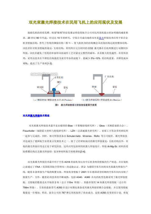
20世纪90年代起,经过近10年的研究,空客公司成功地将双光束激光焊接技术应用于铝合金机身壁板结构,替代了传统的铆接结构(图1),使飞机机身的结构概念从组装结构过渡到整体结构。
该技术针对机身壁板的蒙皮- 长桁结构,利用两台完全相同的CO2 激光器在长桁两侧进行双侧同步焊接,该技术避免了传统的单面焊双面成形工艺对蒙皮完整性的破坏,具有极大的优越性。
有资料表明:采用该技术在不降低结构强度及疲劳寿命的前提下,能减少5%~10% 的结构重量,并降低成本15%,提高了生产效率[1-3]。
双光束激光焊接技术简述双光束激光焊接技术最早是由德国的Bias(不莱梅射线研究所)、Gkss(亥姆霍兹联合会)、Fraunhofer(福朗霍夫材料与射线研究所)、LZH(汉诺威激光研究所)、亚琛工大等众多科研院所一起参与完成的。
同时,相关焊接设备由Schuler-held、M.torres、Rofin 等公司提供。
激光焊接技术也成为了德国航空业的重点发展技术之一。
除了已经研制成功的激光焊接蒙皮- 长桁结构以外,其他的激光焊接应用也正处于研发阶段。
这些应用包括利用机器人焊接角片、焊接Al-Mg-Sc 材料的着陆襟翼结构以及激光焊接铝- 钛异种材料航空座椅滑轨[3-4]。
双光束激光焊接技术最早用于空客A318的前机身以及中后机身两块壁板的生产制造,并在装机之前通过了FAA(美国联邦航空管理局)的适航认证。
图2 为德国空客车间的双光束激光焊接生产线,随着3条焊接生产线的购置安装,焊接机身壁板于2001年在德国诺登哈姆的空客车间内实现了批量生产。
另外,随着此项技术的不断成熟,包括A340、A380 在内的机型也都采用了激光焊接壁板,且壁板的数量也从开始的2块(总计110m 焊缝),到最多使用14块激光焊接壁板(总计约798m焊缝)。
航空工业中的焊接技术发展及展望
航空工业中的焊接技术发展及展望摘要:随着工业4.0的提出以及国家对航空制造业的关注,航空制造业的革命迫在眉睫。
随着世界经济、军事和科技的迅猛发展,航空航天技术已经成为提高国家综合国力的重要途径和手段。
而焊接已成为航空制造工程中最重要的连接方法之一。
本文分析了航空工业中的焊接技术发展及展望、关键词:焊接技术;航空航天工业;发展焊接技术是连接技术中的一部分,是制造技术的重要组成部分,同时也是航空飞机、航空航天发动机、箭弹星船体结构、容器、管路和一些精密器件制造中不可缺少的技术。
在现代生产和制造领域中,越来越多的产品采用各种焊接方法把不同材料、形状、结构和功能的零部件连接成一个复杂的整体,大大简化了构件整体加工的工序,节省了材料,提高了生产效率。
一、国内焊接技术现状国内焊接技术在飞机及发动机上的应用与国外相比还有很大差距,但近年来也取得了长足进步。
我国电子束焊接技术也应用在如起落架、框、腹鳍、受油嘴等飞机结构件上。
发动机零部件采用电子束焊接技术相对较多,如某型发动机高压压气机转子、燃烧室机匣高压涡轮组件等关键件均采用了电子束焊接技术。
我国西飞公司生产的如H6系列飞机和Y7系列飞机,焊接的主要承力结构件是飞机的主起落架和前起落架零组件,焊接工艺均采用手工电弧焊接工艺。
将来要制造的大型运输机,飞机起落架以及主承力梁、翼盒的结构骨架和发动机挂架等将采用焊接结构,其材料有高强度钢,也焊工艺无法满足要求,需要先进的焊接技术。
另外,中国一航第一飞机设计研究院、西飞公司和北京航空制造工程研究所合作,已经将激光焊接技术成功地应用于某型飞机的钛合金腹鳍的焊接。
针对航空发动机的环形板件、薄壁筒形件、机械加工工件圆周对接环焊缝、纵焊缝的自动氩弧焊接,成都焊研科技有限责任公司在美国Jetline公司9500控制器的基础上进行二次开发,结合自身在弧焊控制方面的最新研究成果,研制出一种专门用于航空产品的弧焊控制系统。
此外,国内发动机行业通过多个型号的实践,焊接技术已取得较大的进步,许多新工艺如E B W、I F W、V B、自动氩弧焊、轨迹氩弧焊和弧焊机器人、S P F/D B、P A W及低应力无变形焊接技术等均得到了应用。
造飞机的新技术
造飞机的新技术!!!战争的需求催生了飞机制造技术的进步,世界航空工业发展近百年来,随着复杂航空武器装备的快速升级换代,各项制造技术取得了突飞猛进的发展,在飞机制造领域不断突破、创新。
一代飞机技术需求拉动了飞机制造技术的发展,而制造技术的创新发展又推动了飞机向更高的水平不断换代演进。
本文针对不同时代的飞机技术特点分析了应用于该年代飞机的典型制造技术,将新一代飞机研制中应用的先进制造技术进行总结,与读者分享。
不同时代战机的技术特点自从第一次世界大战中军用飞机首次出现在战场上以来,战斗机经历了近百年的发展,国际航空界依据战斗机的作战任务和其技术特点,以及代与代之间要有质的飞跃、跨台阶式提高的基本原则,对其进行了分“代”。
每代飞机应用的典型材料与典型工艺技术特点如表1所示。
由表1可知,伴随着飞机性能的稳步提升,飞机制造模式也在进行着深刻的变革与创新。
如图1所示,在新型飞机上复合材料、钛合金用量日趋上升,已成为主体材料,新材料的广泛应用给飞机制造业带来更高的技术要求与挑战。
同时,随着数字化技术研究应用的逐步深入,飞机制造正在逐渐摆脱以实物模拟量传递且相互联系的串行制造方式,取而代之的是以三维数字量传递的并行独立制造方式。
新材料与新制造方式的普及带动飞机制造企业在生产技术领域实现突破。
在零件制造领域,全新的零件制造技术逐渐呈现出高精度、大尺寸加工、高材料利用率、近净成形、高效率、柔性工装、无膜制造、数控加工等特点。
在飞机装配领域,传统的模拟量协调、手工钻铆、专用刚性工装、专用量具检测等技术逐渐被数字量协调、自动化钻铆、柔性工装、数字化检测、高效快速研制等技术取代。
新一代飞机研制的先进制造技术1 先进零部件制造技术新一代飞机轻量化、隐身、高可靠性、长寿命、短周期、低成本等研制需求,对飞机制造技术提出了更高的要求,零件制造向无膜敏捷制造、大型整体复合成形、精准制造方向发展。
1.1 结构件高效数控加工技术高效数控加工是数控加工领域的必然发展趋势,是继高速切削、高速加工之后悄然兴起的新观点[1]。
高功率脉冲激光技术及其在工业领域的应用

高功率脉冲激光技术及其在工业领域的应用一、概述高功率脉冲激光技术是一种新型的激光加工技术,它具有高能量、高峰值功率、短脉冲宽度等特点,可以用于材料加工、医疗、环保等领域。
本文将重点介绍其在工业领域的应用。
二、高功率脉冲激光技术的基本原理高功率脉冲激光技术是利用激光器产生的短脉冲激光束对材料进行加工。
其基本原理是:当激光束照射到物体表面时,由于吸收和反射作用,物体表面会产生一个极短暂的高温区域,使材料发生相应变化。
这种变化可以是表面溶解、汽化或者爆炸等。
通过控制激光束的能量和时间,可以实现对材料的加工。
三、高功率脉冲激光技术在工业领域的应用1. 金属材料切割高功率脉冲激光技术在金属材料切割方面具有很大的应用价值。
它可以对各种金属材料进行高效、精确、无损伤的切割,同时可以实现复杂形状的切割。
这种技术在制造业中得到广泛应用,例如汽车制造、电子产品制造等。
2. 3D打印高功率脉冲激光技术在3D打印中也有着重要的应用。
通过控制激光束的能量和时间,可以实现对材料的精确切割和熔化,从而实现3D打印。
这种技术可以用于快速原型制作、医学模型制作等领域。
3. 焊接高功率脉冲激光技术在金属焊接方面也有着广泛的应用。
它可以实现对各种金属材料的高效、精确、无损伤的焊接,同时还可以实现复杂形状结构件的焊接。
这种技术在航空航天、汽车制造等领域得到广泛应用。
4. 表面处理高功率脉冲激光技术在表面处理方面也有着重要的应用。
它可以对各种材料表面进行清洗、去污、除锈等处理,同时还可以实现表面改性和增强。
这种技术在汽车制造、电子产品制造等领域得到广泛应用。
5. 刻蚀高功率脉冲激光技术在刻蚀方面也有着重要的应用。
它可以对各种材料进行高效、精确、无损伤的刻蚀,同时可以实现复杂形状的刻蚀。
这种技术在电子产品制造、光学元件制造等领域得到广泛应用。
四、高功率脉冲激光技术的发展趋势随着科技的不断进步,高功率脉冲激光技术也在不断发展和完善。
未来,这种技术将更加普及和成熟,并将在更多领域得到应用。
先进焊接技术在飞机制造中的应用

等军 民机制造 中, 都相继大量采用 了焊接技术作 为飞机结构 的连接方法 , 焊接技术替代铆接技术 已经 成为一种趋势 。这 种替代不再 是上 世纪 的技术 预言 , 不久 的将来 , 飞机部 件之 间的连接不会完全采 用铆 接或螺接 技术 , 出现 焊接技术 而会
力的不足 ; 同时应重点关注搅拌摩擦焊接技术的发展 动态, 掌握 国外该技 术的应用状况和使 用经验。 关键词 : 飞机 制造 ; 焊接技术 ; 电子束焊 ; 激光焊 ; 搅拌焊 中图分类号 : 2 1 3 4 文献标识码 : 文章编号 :0 89 3 (0 8 0—0 80 V 6 . A 10 —2 32 0 ) 1 0 —4 0
维普资讯
第 2 卷第 1 6 期
2008年 1月
西安航 空技术 高等专科学校学报
J unl f ia eoeh i l ol e o ra o ’nA rt nc l g X c aC e
Vl . 6Nl. 0 2 0 1 1
Jn .200 8 a
2 倍 。焊接技术除 了应用在飞机大件的连接 中以外 , 0 已经
克服 了焊接位置 的严 格 限制 , 部 区域 已经开始 代铆 接 , 局 应 用于机身的制造 中。电子束焊接技 术( 脚
种先进焊接技术 。
收稿 日期 :0 70 —3 2 0 —92
杂, 不可能使用整体锻件或板材制造, 并且主起落架部件和 承力梁公差要求又高, 传统的焊接技术不可能满足要求。洛
维普资讯
第1 期
张颖云 , : 等 先进焊 接技术在 飞机 制造 中的应用
激光焊接技术在航空航天领域中的应用

激光焊接技术在航空航天领域中的应用激光焊接技术是一种高科技焊接方式,它是指使用激光束来加热材料,使其熔化并在焊点处形成焊缝的一种技术。
相对于传统的焊接技术,激光焊接技术在焊接速度、焊接质量、能源消耗等方面有着明显的优势,因此在航空航天领域中的应用日益广泛。
一、激光焊接技术的基本原理激光焊接技术通过激光束的聚焦,将高能量的光束照射到焊接材料上,使其迅速升温并熔化,生成熔池。
在激光束停止照射后,熔池很快冷却凝固,形成焊缝。
激光束的能量密度非常高,可以使焊接材料的温度迅速升高,因此激光焊接能够在非常短的时间内完成焊接,焊接速度快、质量高。
二、激光焊接技术在航空航天领域中的应用在航空航天领域中,激光焊接技术的应用非常广泛,主要体现在以下几个方面:1.飞机结构件的焊接激光焊接技术可以用来焊接飞机结构件,如机翼、机身、发动机舱盖等,这些结构件需要具备轻、强、刚的特点。
激光焊接技术可以控制焊接的能量和速度,从而获得高质量的焊接,避免焊接过程中出现变形、裂纹等质量问题。
2.涡轮叶片的制造涡轮叶片是航空发动机的重要部件,激光焊接技术可以用来制造涡轮叶片。
传统的制造方法需要使用多道工序,而激光焊接技术可以在一次加工中完成整个涡轮叶片的加工,大大提高了生产效率和质量。
3.卫星零部件的制造卫星是航空航天领域中的重要组成部分,激光焊接技术可以用来制造卫星零部件,如外壳、支架等。
这些部件需要具备高强度、轻量化、高精度等特点,而激光焊接技术可以满足这些要求。
三、激光焊接技术的发展趋势激光焊接技术是一种不断发展的焊接技术,未来的发展趋势主要体现在以下几个方面:1.激光功率的提高随着激光技术的不断发展,激光功率不断提高,可以更加深入地焊接各种材料,提高焊接效率和质量。
2.智能化制造未来的制造将更加智能化,激光焊接技术也将实现智能化制造,自动化程度更高,可以实现更高效、更高质量、更高精度的焊接。
3.多模式激光未来激光焊接技术将采用多模式激光,不同的激光模式可以适应不同的焊接需求,从而实现更加精细的焊接。
先进焊接技术在航空制造中的应用

先进焊接技术在航空制造中的应用随着航空业的迅猛发展和技术水平的日益提高,航空制造技术也在不断更新迭代。
其中焊接技术作为航空制造工艺中不可或缺的一环,其性能与技术水平的提升,对于提高飞机的质量、可靠性和安全性起到了重要作用。
本文将介绍先进焊接技术在航空制造中的应用,从焊接过程到焊接材料,从焊接设备到产品质量,深入探讨这些技术在航空制造中的应用和优势。
一、焊接过程焊接作为航空制造中最基本的连接工艺,对整个工艺流程的安全、可靠性和质量等方面有着至关重要的影响。
近年来,先进的焊接技术不断涌现,得到了广泛应用。
1.激光焊接技术激光焊接是目前最为先进的焊接技术之一。
由于其高能密度和较小的热影响区,可实现高质量、高效率的焊接。
具体来说,激光焊接是以激光束为热源,将工件局部加热到熔融状态后冷却成整体,从而实现连接的过程。
该技术应用广泛,可用于铝合金、钛合金及不锈钢等材料的焊接,并具有在狭小的空间内完成焊缝的优点。
2.电子束焊接技术电子束焊接也是一种高精度、高能量密度的非常规焊接技术,其原理是通过一个高能电子束对材料进行熔化和合金化,从而形成焊缝。
相比传统的气体保护焊接,电子束焊接具有焊接点热影响小、焊缝尺寸稳定、成型精度高等优点,适用于高精度、高强度、高温应力下的航空部件的焊接。
3.摩擦搅拌焊接技术摩擦搅拌焊接是一种不用熔化材料直接实现材料连接的新型焊接技术。
它通过旋转摩擦产生热量,然后加压使材料软化而不熔化,最终实现焊接。
与传统的熔覆接头焊接相比,摩擦搅拌焊接技术具有焊接热影响小、无烟尘、无气泡、成型稳定等优点。
二、焊接材料在焊接过程中,选用适宜的焊接材料也至关重要。
航空制造中常用的焊接材料包括铝合金、钛合金、不锈钢等。
这些材料需具备一定的力学性能、耐腐蚀性和高温抗氧化性能等特点。
在铝合金焊接中,常见的焊接材料有铝硅合金、铝镁合金、铝锂合金等。
其中铝硅合金是应用最广的铝合金焊接材料,其成本低、焊接强度高。
而在航空工业中,钛合金也是非常重要的材料,其高强度、轻量、高温强度和良好的可加工性使其成为航空航天、航空发动机等重要部件的首选材料。
激光焊接中的材料熔化过程数值模拟

激光焊接中的材料熔化过程数值模拟激光焊接是一种高效、精确的焊接方法,被广泛应用于汽车、航空、电子、机械等行业。
在激光焊接中,材料的熔化过程至关重要,对焊缝的质量和性能有着决定性的影响。
因此,通过数值模拟对激光焊接中的材料熔化过程进行研究,有助于优化焊接工艺、提高焊接质量。
首先,我们需要了解激光焊接中的材料熔化过程。
在激光束的照射下,工件表面的温度迅速升高,当温度达到了材料的熔点时,材料开始融化。
随着激光束的移动,焊缝部位的材料被加热和熔化,形成液态池。
激光束移动的方向决定了液态池的形状和大小。
当激光束停止照射时,液态池开始冷却固化,形成焊缝。
由于激光焊接中涉及的物理、化学、热力学、流体力学等多学科知识,直接进行实验研究非常耗时耗力。
而数值模拟则可以通过计算机模拟并预测激光焊接中的材料熔化过程,大大减少了实验成本。
数值模拟可以根据激光焊接中的材料属性、激光束参数、焊接速度等因素,建立对应的数学模型,从而预测熔化过程和焊缝质量。
一般来说,激光焊接中的材料熔化过程数值模拟包含以下几个步骤:第一步,建立数学模型。
根据焊接过程中的物理规律,建立数学模型是进行数值模拟的第一步。
数值模拟的计算结果的准确性和可靠性取决于数学模型的正确性和精度。
因此,建立数学模型是数值模拟中至关重要的一步。
第二步,确定材料属性。
不同的材料具有不同的熔点、热导率、密度等物理特性,这些特性将影响材料的熔化过程。
因此,在进行激光焊接中的材料熔化过程数值模拟前,需要对材料的物理性质进行确定。
第三步,确定激光参数。
激光参数包括激光功率、扫描速度、焊缝形状等。
这些参数会对材料熔化过程产生显着影响,因此需要进行合理的设置。
第四步,计算熔化过程。
根据数学模型、材料属性和激光参数,计算机模拟出焊接过程中材料的熔化和形成液态池的过程。
通过模拟,可以得出不同工艺参数下的液态池的尺寸、形状和温度等信息。
第五步,计算焊缝质量。
根据计算结果,可以预测焊缝的质量和性能。
关于电子束焊接应用

关于电子束焊接应用机械制造及自动化专业1班小组成员:组长:刘浩王静泽,陈磊,杨一,马自超,杨成林,刘淑芳,王晓雪摘要:在当今时代,电子束焊接术的每一个进步的积累使人类的航空制造技术更加的完善和强健。
电子束焊接技术因其高能量密度和优良的焊缝质量,率先在国内航空工业得到应用。
先进发动机和飞机工业中已广泛应用了电子束焊接技术,取得了很大的经济效益和社会效益,该项技术从上世纪八十年代开始逐步在向民用工业转化。
汽车工业、机械工业等已广泛应用该技术。
最早研发电子束技术的国家是德国,凭借先进和敏锐的科学研发能力,德国的电子束当前已经处于行业中的领先地位。
电子束焊接的应用涵盖了从薄膜焊接到一次性接合200mm得两个共建的焊接。
电子束技术的产生使得机械零件的设计具有了更多的自由度,同时,它还广泛应用在航空航天和太空开发部件的加工、船舶制造业或电子和汽车工业的批量生产上。
关键词:电子束焊接应用一、电子束焊的工作原理和分类高电位能使电子得到高能量,通常表现为电子具有很高的动能。
电子束焊正是利用高速电子流轰击工件接缝处所产生的热能,使金属熔合的一种焊接方法。
电子轰击工件时,动能转变为热能。
会聚的电子束用于焊接时可达到的功率密度非常高,所以可以焊接其他方法不能焊接的材料,并能使焊缝非常小。
同时电子束的快速可控性更是大大拓宽了它的用途。
1、工作原理电子束是从电子枪中产生的。
通常电子是以热发射或场致发射的方式从发射体(阴极)逸出的。
这时电子的能量只有几个电子伏特,在25~300kV的加速电压的作用下,电子被加速到0.3~0.7倍的光速,具有一定的动能,这时电子的功率已大大提高,经电子枪中静电透镜和电磁透镜的会聚作用,电子成为功率密度很高的电子束。
这种电子束撞击到工作表面,电子的动能就转变为热能,使金属迅速熔化和蒸发。
在高压金属蒸汽的作用下熔化的金属被排开,电子束就能继续撞击深处的固态金属,很快在被焊工件上“钻”出一个小孔,小孔的周围被液态金属包围。
激光焊接调研报告
激光焊接调研报告激光焊接调研报告激光焊接是一种现代化的焊接技术,利用高能量密度的激光束,将焊接材料加热至熔化或半熔状态,通过材料的自身表面张力实现焊接。
该技术具有高精度、高效率和非接触性等优点,在工业生产中得到广泛应用。
首先,激光焊接具有高精度的特点。
由于激光束的高能量密度和集中性,焊接过程中的热影响区域相比传统焊接方法更小,可以实现精确控制焊缝的形状和尺寸。
这对一些对焊接质量要求较高的行业尤为重要,比如汽车制造和航天航空工业。
其次,激光焊接具有高效率的特点。
激光焊接所需的能量较低,且热输入量小,焊接速度快,可以节约大量能源和生产时间。
另外,激光焊接机器设备小巧,占地面积小,不需要太多人力资源,节约了人力成本。
再次,激光焊接具有非接触性的特点。
激光焊接不需要直接接触焊接材料,避免了由于接触引起的杂质和气泡的产生,可以实现清洁的焊接过程。
此外,激光焊接还可以实现远距离焊接,无需对焊接材料进行特殊的定位和固定,提高了焊接的灵活性和便捷性。
然而,激光焊接也存在一些问题和挑战。
首先,激光焊接设备和技术相对成熟,但仍然需要不断改进和创新,提高焊接质量和效率。
例如,对材料的选择和激光参数的优化还需要进行更深入的研究和探索。
其次,激光焊接的成本相对较高。
激光焊接设备的价格较高,维护和保养成本也较高,这对中小型企业来说可能是一项负担。
此外,操作人员对激光设备的操作技术要求较高,需要经过专业培训和技能提升。
最后,激光焊接还存在安全隐患。
激光束具有高能量密度,对人体和环境具有一定的危害,如果不正确使用或保护不当,可能导致人身伤害或设备损坏。
因此,在激光焊接过程中,应加强安全教育和保护措施,确保操作人员和设备的安全。
总之,激光焊接作为一种先进的焊接技术,有着广阔的应用前景。
虽然仍面临一些技术和经济上的挑战,但通过不断的研发和推广应用,激光焊接将在各个行业中发挥更大的作用,推动工业制造的进一步升级和发展。
激光焊接在航空航天工业中的应用
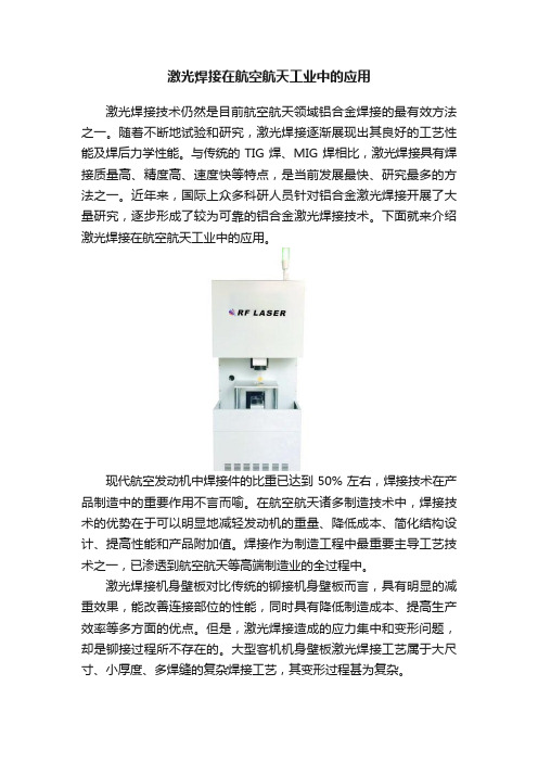
激光焊接在航空航天工业中的应用激光焊接技术仍然是目前航空航天领域铝合金焊接的最有效方法之一。
随着不断地试验和研究,激光焊接逐渐展现出其良好的工艺性能及焊后力学性能。
与传统的TIG焊、MIG焊相比,激光焊接具有焊接质量高、精度高、速度快等特点,是当前发展最快、研究最多的方法之一。
近年来,国际上众多科研人员针对铝合金激光焊接开展了大量研究,逐步形成了较为可靠的铝合金激光焊接技术。
下面就来介绍激光焊接在航空航天工业中的应用。
现代航空发动机中焊接件的比重已达到 50% 左右,焊接技术在产品制造中的重要作用不言而喻。
在航空航天诸多制造技术中,焊接技术的优势在于可以明显地减轻发动机的重量、降低成本、简化结构设计、提高性能和产品附加值。
焊接作为制造工程中最重要主导工艺技术之一,已渗透到航空航天等高端制造业的全过程中。
激光焊接机身壁板对比传统的铆接机身壁板而言,具有明显的减重效果,能改善连接部位的性能,同时具有降低制造成本、提高生产效率等多方面的优点。
但是,激光焊接造成的应力集中和变形问题,却是铆接过程所不存在的。
大型客机机身壁板激光焊接工艺属于大尺寸、小厚度、多焊缝的复杂焊接工艺,其变形过程甚为复杂。
钛合金主要广泛用在飞机上,并已由次承力结构件转为主结构件,铝合金是运载火箭及各种航天器的主要结构材料。
先通过对比铝合金、钛合金的传统焊接与激光复合焊,突显出激光加工有能量集中、易于操作、高柔性化、节能环保和高质高效等优点。
武汉瑞丰光电激光设备凭借多年的激光研发经验,产品技术成熟,产品性能安全稳定。
瑞丰光电激光电始终坚持“质量第一、服务第二、价格第三”的态度,给客户提供最优质的产品及服务。
以上就是激光焊接在航空航天工业中的应用,激光焊接的最大优点是其能量集中,形成焊接接头深宽比大、焊接变形较小。
随着激光光束质量的不断改进,激光焊接现已成为一种成熟的焊接方法,广泛地应用于国民经济和国防建设的不同领域。
激光束焊接技术在航空航天领域的应用

激光束焊接技术在航空航天领域的应用引言随着航空航天行业的不断发展,对于焊接技术的要求也越来越高。
传统的焊接方法,如电弧焊接和气体保护焊接,存在着一些局限性,无法满足航空航天领域对焊接质量、效率和可靠性的严苛要求。
而激光束焊接技术凭借其高能密度、小热影响区、精确控制等优势,日益成为航空航天领域的焊接新选择。
本文将深入探讨激光束焊接技术在航空航天领域的应用,并分析其优势和未来发展趋势。
一、激光束焊接技术的原理与特点1. 原理:激光束焊接技术是利用高能激光束照射材料表面,通过光能转化为热能,使焊接材料局部加热熔化,然后形成牢固的焊缝。
2. 特点:a. 高能密度:激光束具有高能浓度和聚焦性,可以将光能集中在焊接区域,使焊接材料迅速加热到熔化温度,实现高质量焊接。
b. 小热影响区:由于激光束焊接过程瞬间完成,热影响区小,减少了热变形和应力集中的可能性,提高了焊接接头的精度和强度。
c. 精确控制:激光束焊接技术可以通过调整激光参数、焊接速度和光斑大小等参数,实现对焊接过程的精确控制,达到各种焊接质量需求。
二、激光束焊接技术在航空领域的应用1. 航空结构件焊接:航空器的金属结构件通常需要进行焊接,如飞机机身、引擎零部件等。
激光束焊接技术可以在不破坏材料机械性能的情况下,实现高强度、高质量的焊接。
2. 轻型材料焊接:为了提高航空器的载荷能力和燃料效率,航空领域开始采用轻型材料,如铝合金和镁合金。
这些材料在传统的焊接方式下容易产生缺陷。
激光束焊接技术能够在保证焊接质量的前提下,实现对轻型材料的高质量焊接。
3. 可焊接材料扩展:激光束焊接技术可以焊接多种可焊接材料,如不锈钢、钛合金、镍基合金等,拓宽了航空领域的焊接范围。
4. 修复与加工:航空器在使用过程中可能会遭受磨损、疲劳等损伤,需要进行修复。
激光束焊接技术可以进行局部修复焊接,将损伤部分重新焊接到整体上,提高了航空器的使用寿命。
三、激光束焊接技术在航天领域的应用1. 航天器结构件制造:激光束焊接技术可以实现航天器结构件的高质量焊接制造,如航天飞机的航空舱、发动机舱等。
激光加工过程的建模与仿真

激光加工过程的建模与仿真激光加工是一种高效、高精度的现代加工技术,在制造行业中得到了广泛应用。
其基本原理是利用能量高度集中的激光束在材料表面扫描或重复加工形成所需形状。
但是,激光加工是一个非常复杂的过程,需要精确的模拟和仿真来实现预测、优化和控制,因此激光加工过程的建模和仿真越来越受到关注。
一、激光加工的基础原理在激光加工中,激光束被聚焦在一个非常小的点上,该点的温度高到足以使材料熔化或蒸发,从而形成所需的形状。
加工速度、功率密度、材料特性、激光束直径和工作距离等因素对加工效果有很大影响。
激光加工技术通常分为三种类型:雕刻、切割和焊接。
雕刻是在工件表面深度刻上一个图案或文字。
激光切割是将工件切割成所需的形状。
激光焊接是将工件上的两个或多个零件焊接在一起。
二、激光加工仿真的必要性由于激光加工过程涉及许多参数和复杂的物理机制,因此对其进行系统分析和优化是非常有挑战性的。
在实际操作中,必须考虑到各种因素的相互作用,以得到正确的结果。
考虑这些因素并学习实施激光加工过程并不容易。
因此,在实际操作之前,使用计算机模拟来预测加工品质和瑕疵的可能性变得越来越重要。
基于此,激光加工仿真的必要性越来越得到重视。
三、激光加工仿真的方法激光加工仿真方法可以基于物理方法或统计方法。
物理方法基于激光加工的基本原理进行模拟。
统计方法则通过建立统计模型来模拟激光加工过程。
模型越复杂、越真实,精度就越高,建模越需要更多的时间和实验数据,并且需要计算和编程的技能。
四、激光加工建模的挑战激光加工建模的主要难点在于开发适用于各种不可预测的材料的精细模型。
建模时需要考虑到诸如熔化、固化和膨胀等物理现象带来的影响,以及材料特性、工作环境和光学参数等。
此外,研究过程还需要协调工作区和材料特征的变化,以及激光发射时产生的瞬态干扰和其他干扰。
五、激光加工仿真的应用激光加工仿真的应用非常广泛,可用于改善加工品质、提高生产效率和减少运营成本。
在汽车、航空航天、消费品和医疗设备等行业中,激光加工仿真已得到广泛应用。
激光技术在工业应用中的前景
激光技术在工业应用中的前景激光技术,这玩意儿可真是个神奇的存在!就拿我前阵子的一次经历来说吧,我去参观了一家汽车制造工厂,那场面,让我对激光技术在工业应用中的前景有了更深的感受。
一走进工厂,首先映入眼帘的是一台巨大的激光切割机。
那机器就像一个精准的超级剪刀,快速而准确地将钢板剪成各种形状。
以前我总觉得切割金属得靠那种又笨又重的传统工具,还得工人师傅们费好大的劲儿。
但眼前这激光切割机,简直太牛了!它发出的那束光,又细又亮,就这么轻轻一扫,坚硬的钢板瞬间就被切开,切口还特别平滑,没有一点儿毛刺。
激光焊接也是让我大开眼界。
在生产线上,工人们正在用激光焊接汽车的零部件。
那激光束就像一根神奇的针线,把两个部件紧紧地“缝”在一起,而且焊接的地方强度高,密封性好。
不像以前的焊接方法,不仅效率低,还容易出现瑕疵。
在印刷行业,激光技术也有着出色的表现。
还记得有一次我去打印店打印东西,看到他们用的激光打印机,那打印速度和质量,简直绝了!无论是彩色的图片还是精细的文字,都能打印得清晰逼真。
而且激光打印机的稳定性也很好,不像喷墨打印机,有时候会出现喷头堵塞的问题。
再说说激光打标,这在工业产品的标识和防伪方面可发挥了大作用。
像一些电子产品、珠宝首饰上的标记,用激光打出来的又清晰又持久,还不容易被篡改。
激光技术在材料加工方面的优势也越来越明显。
它可以对各种材料进行表面处理,比如硬化、镀膜等,提高材料的性能和使用寿命。
而且激光还能用于快速成型,直接把设计好的模型变成实物,大大缩短了产品的开发周期。
随着科技的不断发展,激光技术的应用前景简直是一片光明。
比如说在医疗领域,激光可以用来治疗各种疾病,像激光近视手术,让很多人摆脱了眼镜的束缚;在通信领域,激光通信能实现高速、大容量的数据传输。
在未来,我相信激光技术会变得更加普及和强大。
它可能会让工厂的生产效率更高,产品质量更好,成本更低。
说不定有一天,我们家里的各种用品都是用激光技术制造出来的,那该多酷啊!总之,激光技术在工业应用中的前景真是不可限量。
焊接技术在航空航天工业中的应用
航空航天科学技术DOI:10.16660/ki.1674-098X.2005-1012-9786焊接技术在航空航天工业中的应用冯瑞(中国航空工业集团公司西安航空计算技术研究所 陕西西安 710000)摘 要:随着国家经济实力不断增强,在科学技术不断发展的双重保障下,我国焊接技术发展越来越成熟。
航空航天工业一直是作为国家实力的一项重要象征存在的,并且在整个航空航天工业中,焊接技术的应用是非常重要的一环,它是制造技术的主要组成部分。
因此本文的探析重点就放在焊接技术与航空航天工业之间的应用关系上,以此来进行深入研究。
关键词:焊接技术 航空航天工业 应用 分类中图分类号:G623 文献标识码:A 文章编号:1674-098X(2020)10(b)-0004-03Application of Welding Technology in Aerospace IndustryFENG Rui(AVIC, Xi'an Institute of Aeronautical Computing Technology, Xi'an, Shaanxi Province, 710000China)Abstract:With the increasing national economic strength, under the double guarantee of continuous development of science and technology, China's welding technology development is becoming more and more mature.The aerospace industry has always been an important symbol of national strength and in the entire aerospace industry., The application of welding technology is a very important link., It is the main component of manufacturing technology. Therefore, this paper focuses on the application of welding technology and aerospace industry in order to carry out in-depth research.Key Words: Welding technology; Aerospace industry; Application; Classification从技术品种来看,焊接技术属于链接技术中的一环。
激光钎焊仿真毕业设计
激光钎焊仿真毕业设计激光钎焊仿真毕业设计毕业设计是每个大学生必须完成的一项重要任务,它既是对所学知识的综合应用,也是对自己能力的一次全面考核。
在我读研期间,我选择了激光钎焊仿真作为我的毕业设计课题。
本文将详细介绍激光钎焊仿真的背景、原理和实验过程,以及我在设计过程中遇到的困难和解决方法。
一、激光钎焊仿真的背景随着科技的不断进步,激光钎焊技术在工业生产中得到了广泛应用。
激光钎焊具有高能量密度、热影响区小、焊接速度快等优点,因此被广泛应用于汽车制造、航空航天等领域。
然而,在实际应用中,激光钎焊过程中的温度分布、熔池形状等参数很难直接观测和测量,因此需要通过仿真来进行分析和优化。
二、激光钎焊仿真的原理激光钎焊仿真主要基于有限元分析方法,通过建立数学模型来模拟激光钎焊过程中的温度场、应力场等物理现象。
首先,需要对钎焊过程进行建模,包括激光束的传输、材料的热传导和相变等。
然后,通过求解数学模型,得到钎焊过程中的温度分布、熔池形状等参数。
最后,通过对仿真结果的分析和优化,可以改善激光钎焊的质量和效率。
三、激光钎焊仿真的实验过程在我的毕业设计中,我选择了一种常用的激光钎焊材料——铝合金进行仿真实验。
首先,我需要对铝合金的材料性质进行研究和分析,包括热导率、熔点等参数。
然后,我使用ANSYS软件建立了钎焊过程的数学模型,并设置了激光功率、扫描速度等参数。
接下来,我进行了多组实验,通过改变激光功率和扫描速度等参数,观察钎焊过程中的温度分布和熔池形状的变化。
最后,我对实验结果进行了统计和分析,得出了一些有价值的结论。
四、在设计过程中遇到的困难和解决方法在进行激光钎焊仿真的过程中,我遇到了一些困难。
首先,建立数学模型需要对材料的性质和钎焊过程的物理现象有深入的了解。
为了解决这个问题,我进行了大量的文献阅读和实验研究,提高了自己的专业知识水平。
其次,仿真过程中需要对软件进行熟练操作,这对我的计算机技术能力提出了一定的要求。
激光束焊接原理及应用完整版课件

数据分析与优化
利用大数据技术对焊接过程中的数据 进行分析,不断优化焊接参数,提高 焊接质量。
智能预测与维护
通过机器学习等技术预测设备故障, 实现设备的预防性维护,提高设备利 用率。
CHAPTER
激光束焊接质量控制与检测
激光束焊接缺陷与防止措施
01
气孔
02
裂纹
03
咬边
激光束焊接质量检测方法
射线检测
高功率、高效率激光束焊接技术发展
高功率激光器
高效能量转换
复合激光束焊接技术研究与应用
激光-电弧复合焊接
将激光束与电弧复合使用,能够同时利用两者的优势,提高焊接速度和质量。
激光-超声复合焊接
利用超声波的振动效应,能够改善焊接接头的组织和性能,提高焊接质量。
激光束焊接在新能源、环保领域的应用前景
新能源领域
激光束焊接的工艺参数
激光功率
光斑直径
焊接速度
保护气体
CHAPTER
激光束焊接设备与技术
激光束焊接设备的组成
光束传输系统
将激光束从激光器 传输到工作区域。
工作台
承载和移动焊接件 的部分。
激光器
产生并控制激光束 的关键部分。
聚焦系统
将激光束聚焦到所 需直径,以达到焊 接要求。
控制系统
控制整个焊接过程, 包括激光输出、工 作台移动等。
激光束焊接技术能够应用于太阳能电池板、锂离子电池等新能源产品的制造中,实现高质量、高效率的焊接。
环保领域
激光束焊接技术具有无污染、低能耗等优点,在环保领域的应用前景广阔,如环保设备、水处理设备等制造过程 中可采用该技术。
激光束焊接技术的教育与培训展望
专业人才培养
- 1、下载文档前请自行甄别文档内容的完整性,平台不提供额外的编辑、内容补充、找答案等附加服务。
- 2、"仅部分预览"的文档,不可在线预览部分如存在完整性等问题,可反馈申请退款(可完整预览的文档不适用该条件!)。
- 3、如文档侵犯您的权益,请联系客服反馈,我们会尽快为您处理(人工客服工作时间:9:00-18:30)。
ORIGINAL ARTICLEKnowledge modelling for laser beam welding in the aircraft industryXiaofeng Sun &Essam Shehab &Jörn MehnenReceived:11January 2012/Accepted:27June 2012/Published online:11July 2012#Springer-Verlag London Limited 2012Abstract This paper presents a knowledge model of the laser beam welding (LBW)in the aircraft industry,which is developed through the utilisation of integration definition for function modelling and concept mapping.The devel-oped knowledge model has been captured in the form of rules and recommendations,which is commonly used as guidelines in this field,and represented with unified model-ling language.The LBW component development com-prises four key stages,namely,structure design,process planning,fixture fabrication and component fabrication.This has been achieved through the adoption of a three-phase qualitative research methodology:data collection and analysis,knowledge model development and validation.The captured knowledge in the form of rules and recom-mendations has developed an understanding of the LBW in the aircraft industry and improved the structure design and process planning from joint type selection,structure dimen-sion definition and process parameter optimisation,etc.A prototype handbook has been developed based on skin –stringer connection of aircraft fuselage to guide designers and engineers directly in developing laser beam-welded fuselage panels.The procedure of knowledge modelling for the LBW as well as the methods and tools adopted can be applied to other processes.The developed knowledge model has been validated through a case study.Keywords Laser beam welding .Aircraft industry .Structure design .Process planning .Knowledge modelling1IntroductionAlthough the application of composites has been increasing dramatically recently,reaching 50and 53%of the structure mass for B787and A350,respectively,light metals,such as aluminium and titanium,still account for over 30%of the structure mass [16].The development of the third generation of Al-Li alloys and Al-Mg-Sc alloys illustrates that metal technology in the aircraft industry will keep developing [12].Thus,a study of technologies and manufacturing processes which focuses on these light metals still has great potential.The laser beam welding (LBW)process has been develop-ing rapidly in recent decades as it is possible to manufacture joints of most light metals and their combinations for its high power intensity [21].It is a trend of the development of the metal fuselage in the aircraft industry as it is capable of inte-grating and simplifying the structure [20],as well as reducing the weight and cost [23],which meet the main concerns of the aircraft industry.Furthermore,the high production rate and automation of LBW can easily solve the shortage of the tradi-tional riveting process which is intensive in process time [7].Structure design and process planning are always guided or restricted by rules and recommendations in the aircraft industry to reduce mistakes induced by individuals.Thus,it will contribute to the application of the LBW process in this field if knowledge of the process is captured in the form of rules and recommendations and utilised to guide structure design and process planning.However,such rules and recommendations for the LBW process are still lacking in the aircraft industry today.2Literature reviewKnowledge modelling is a process to create knowledge,which is a key procedure within knowledge managementX.SunShanghai Aircraft Manufacturing Co.,Ltd.,Shanghai 200436,ChinaE.Shehab (*):J.MehnenManufacturing and Materials Department,Cranfield University,Bedford MK430AL,UKe-mail:e.shehab@Int J Adv Manuf Technol (2013)66:763–774DOI 10.1007/s00170-012-4364-0and is necessary for a company to innovate products and processes.Davenport and Prusak [6]believe that knowledge modelling contributes to a developed understanding of the knowledge,including knowledge source,the input and out-put,the flow of knowledge and other variables.Mohammad et al.[15]has developed two different frameworks for capturing tacit and explicit knowledge,which are concise and cost efficient and could be used by most large organ-isations.A knowledge web-based system is developed to support collaboration in a global engineering environment [19],which is capable of distributing the product life cycle information and knowledge effectively.For material pro-cessing,Rentzsch et al.[18]recommend knowledge map-ping to locate knowledge about the impact of process stages to the product attributions.With this method,the impact of every process stage on every product attribute can be cap-tured and visualised systematically.Hunter et al.[11]sug-gest a knowledge template that defines the common entities and inference processes in the fixture design process for machining,which is able to be reused to other types of fixtures uses like assembly or welding.Wang et al.[24]proposes a rough set-based knowledge modelling method for the aluminium alloy pulsed gas tungsten arc welding process to obtain the knowledge and make it easily under-stood and revised,which is regarded as the basis of the intelligent control of the welding process.LBW is a fusion welding process which is capable of joining two or more pieces of material by the interaction of the laser beam and the material surface (American Welding Society (AWS)[2]).There are two distinctly different modes of LBW which are commonly referred to as conduc-tion mode welding and keyhole mode welding.According to the different energy sources,LBW can be classified as single beam welding,dual beam welding and laser-X hybrid welding (X is a different welding method)as illustrated in Fig.1.For a T butt joint,dual beam welding is preferred for lower distortion resulting from symmetric welding.Single beam welding for this configuration easily causes residual stress and distortion [8].Laser-X hybrid weldingcombinesFig.1Laser beam welding methods (AWS 2010)Fig.2A typical structure of a skin –stringer connectionthe advantages of both welding technologies because it introduces a secondary energy source to the weld pool area.Schubert et al.[21]state that LBW is capable of manu-facturing joints of most light metals and their combinations,such as aluminium,magnesium and titanium,because of its high energy density.Brenner et al.[4]compare LBW with riveting and found that the LBW process illustrates signifi-cant advantages,such as weight reduction of the aircraft fuselage panel,operation cost saving and corrosion resis-tance improvement.Other advantages,such as improvement of production rate and simplicity of fixture are also remark-able.Rendigs and Knower [17]found in their research that the LBW speed can reach 8to 10m/min while the compa-rable riveting process is only 0.15to 0.25m/min.It is two times of the automatic riveting speed [14].Recent research by Li et al.[13]confirm that the LBW process gains more advantages from high power density and welding speed,such as a small heat affected zone,low distortion,high joint strength and high production rate,compared with traditionalwelding process,such as gas metal arc welding.Walz [23]proposes a solution to reduce the influence of high capital cost of a LBW system by sharing the system to other processes,such as laser cutting,surface hardening and trim-ming.Because LBW is an accurate process,close fitting,well clamping and exact positioning are required;otherwise,the accurate beam/joint alignment cannot be achieved and the workpiece cannot be welded properly.It is found that a stable LBW process depends on defining and controlling the processing parameters which influence process stability for high-quality welds at high welding speeds [5].The laser power [25],welding speed [1]and focal position [5]have been studied and identified to be the most important process parameters for the LBW process as they are related to a hidden parameter called energy density which is a key factor of penetration welding and will influence the weld formation.All these three parameters are found to have great influence on tensile strength of the welds [1,5,25].Anawa et al.[3]develop a mathematical model to describe the influence of theseTable 1Sample of questions and their responses Sample of questionsResponseQ1.For chemical-milled skin,what tolerance is usually given in the design stage?Are there any rules?To investigate the design tolerance and rules of chemical-milled skins Q2.How to verify that the whole LBW procedure is under control?What are the vehicles?To investigate the method of process control Q3.How to locate and clamp the skin?How to define the fixture tolerance?To investigate the method and tool for skin locating and clamping,as well as the fixture toleranceJointWelding speedFocal opticsLaser PowerProtection gasFiller metalMaterialProcess control StructureProcess SpecificationMaterial controlEquipment ProcedureProcess parameters ProcessFacility controlDesign factorsProcess factorsProduct Resource Personnel Fixture GeometryDimensionToleranceWeldbilitypreparationFig.3A concept map of design and process factors for laser beam weldingparameters on the fusion zone area and to predict its value, which is capable of optimising the process parameters.The utilisation of protection gas[25],filler metal[9,26]and joint preparation[5,10]have also been studied and found effective to the final weld.LBW is a possible solution that contributes to weight reduc-tion of fuselage panels and has been studied by many research-ers.However,most of these research studies are about weld properties of a certain material based on experiments.There are only a few research studies about knowledge modelling of the LBW process and even fewer about knowledge modelling of the LBW process in this field in the form of rules and recommen-dations,aiming to guide structure design and process planning. 3Research methodologyThe approach adopted in this paper to build the knowl-edge model for the LBW process in the aircraft industry is based on a literature review and investigation in prac-tice.A qualitative methodology was adopted in this paper,using the primary tools of interviews,question-naire and literature review to collect data and information and using concept mapping,rules and recommendations, integration definition for function modelling(IDEF0)and unified modelling language to build the knowledge mod-el.The research methodology comprises three major phases:data collection and analysis,knowledge model development and validation.Data collection and analysis is essential for knowledge model development as the final results will be greatly influenced by the efficiency of data and information. Thus,a questionnaire,a number of semi-structured inter-views and a comprehensive literature review have been conducted in this phase to collect enough efficient data and information.The semi-structured interviews were conducted with specialists from an aerospace company in China to collect information from industry.Based on this,concept mapping has been utilised to analyse and categorise the collected information.In the second phase,process mapping with IDEF0and concept mapping are used to further analyse the LBW process in the aircraft industry,based on the collected data in the previous phase.An IDEF0map was built for the LBW structure development procedure to structure the col-lected information and identify the considerations of this procedure.Then the knowledge about these considerations can be identified,captured and represented,so as to develop the knowledge model.The skin–stringer connection of an aircraft's low fuselage panel(see Fig.2)has been chosen as the case to be studied in the third phase because it is a typical structure in the aircraft industry.The proposed knowl-edge model is applied to this specific component for validation.FinalSDRR: Structure Design Rules and RecommendationsPPRR: Process Planning Rules and RecommendationsQC: Quality ControlFig.4Top-level route map oflaser beam welding componentdevelopmentFig.5Develop laser beam welding component4Data collection and analysisThe semi-structured questionnaire was designed to capture data on fuselage panel structure design (including geometry,dimension and tolerance),LBW process planning and fix-ture design.Eleven experts and engineers from a leading aircraft manufacturing company in China were interviewed in this stage,including three structure designers,two man-ufacturing engineers,two fixture/tooling designers and four LBW process researchers.Seventeen questions were designed.Table 1illustrates three examples of questions and their responses.The question “For chemical-milled skin,what tolerance is usually given in the design stage?Are there any rules?”was designed to investigate the design tolerance of chemical-milled skins,whilst the question “How to verify that the whole LBW procedure is under control?”was asked to investigate the LBW procedure is followed.It is widely accepted in the manufacturing industry that the data and information of each production can be divided into three domains:product,process and resource.This is defined in the structure of ISO 10303-214(ISO/TC184/SC4)and other standards.It is obvious that the LBW process in the aircraft industry should follow this basic principle.In this paper,product information includes design factors induced in the design stage,such as structure dimensionC7: material specification C4: current manufacturing capability O1: material choice O2: structure model O3: technique requirement O4: quality control plan O 5: work order O6: procedure O7: work instruction O8: NC code O9: fixture design O10: fixture O11: final product O12: best practice or lessons learntFig.6Decomposed map for develop laser beam welding componentC2: strength requirementC3: rules and recommendationsC4: current manufacturing capability Fig.7Design structure for the laser beam weldingand tolerance,whilst process and resource information means process factors induced in the process planning stage,such as procedure,process parameters and fixture (see Fig.3).The LBW process capabilities are greatly influenced by these factors.Based on the collected information from the questionnaire,semi-structured interviews and literature review,all the LBW process-related information is classified as design factors and process factors,i.e.two aspects.Furthermore,the design fac-tors are further categorised as material and structure aspects,while the process factors are categorised as procedure,processparameter,fixture design and process control,i.e.four aspects.A concept map including all of this information has been built to show the inter-relationships of these aspects,as illustrated in Fig.3.This provides a foundation for the knowledge modeldevelopment.C3: rules and recommendationsC4: current manufacturing capability C5: other regulations of the company Fig.9Plan process for the laser beam welding componentRRSSDRRProductGeometryDimension Telorance PPRRProcessProcedure Laser powerFocal positionWelding speedFiller metalShielding gas Joint preparationResource FixtureFig.10Categorisation of captured knowledge about laser beam welding5Knowledge model development5.1Laser beam welding component development procedure The top-level route map of the LBW component development procedure in the aircraft industry is illustrated in Fig.4.The whole procedure was broken down into four key stages,namely,structure design,process planning,fixture fabrication and component fabrication.The design and process planning is guided and assessed by certain rules and recommendations to ensure the design and process quality,while the fixture and component fabrication are assessed by quality control require-ments.Rules and recommendations play an important role in this procedure as it is possible to make the design and process suitable for LBW at the conceptual design stage so as to reduce the cost of rework after releasing the design and process.IDEF0was utilised to build a process map of LBW component development procedure for its advantages inprocess knowledge modelling as shown in Fig.5.The main inputs of LBW component development include upstream design inputs (including surface geometry,frame plane and stringer axis)and raw materials,whilst the outputs include final product as well as best practice or lessons learnt.The procedure is controlled by geometry restriction,strength requirement,structure design rules and recommendations (SDRRs)and process planning rules and recommendations (PPRRs),current manufacturing capability,other regula-tions of the company,material specification and process specification.Personnel (including structure designers,pro-cess engineers,fixture designers and welding operators),tools (including computers and design software etc.),Inter-net/intranet and facilities (fixture fabrication equipment,LBW equipment etc.)are the main mechanics of this procedure.This procedure contains several stages according to the top-level route map.Thus,a decomposed IDEF0map was developed to further analyse this procedure as illustrated in Fig.6.As “fabricate fixture/tooling ”and “fabricate LBW component ”are both controlled by the outputs of the “plan process for LBW component ”,they are not considered as key stages influencing the LBW process capabilities.Most of the LBW process variables are defined and prepared in the design and planning stages.Thus,the identified LBW considerations have been focused on structure design and process planning.5.1.1Structure design considerationsThe design structure for the LBW component was decom-posed into “design skin structure ”,“design stringer struc-ture ”and “design weld seam ”as illustrated in Fig.7.Additionally,the joint type as well as the structure for skin and stringer should be selected before the design isconducted.Fig.11Example of rules and recommendations for productdomainFig.12Example of rules and recommendations for resource domainOne of the main considerations for LBW structure design is the material,including what material to choose and how to ensure the quality of the material.The weldability of materials is the first influencing factor of material choice because it determines the weldability of the component directly.Material with better weldability as well as high strength and toughness is preferred for laser beam-welded component.To ensure the quality of material,a material specification defining the trademarks of materials as well as suppliers is specified during this stage to give the process planning a guideline or regulation for material preparation.The joint structure should adequately fulfil its service requirements,and the configuration and size should bepractical for LBW.The dimension of the skin is limited by the LBW equipment and the process margin.If there is no special requirement,the standard extruded “L ”profile (see Fig.8)with simple section geometry is preferred and a profile structure with various thicknesses should be avoided.For any developed aircraft,it is necessary to demonstrate that safety and airworthiness will be given throughout the whole lifetime of the structure.Thus,proper technique requirements should be established;the most important one is process specification,containing all the information and requirements for a stable process.Weld defects criteria should also be established so that the welding results can be assessed.However,the requirements should also bepracticalFig.13Example of rules and recommendations for processdomainFig.14Schematicrepresentation of laser beam welding in the aircraft industryfor the current LBW process capabilities.High technique requirements will not provide extra safety but will increase the operation cost and make the process uneconomic.5.1.2Process planning considerationsFigure 9illustrates the decomposed IDEF0map for the plan process of LBW component.This action is decomposed into “plan LBW process ”,“plan skin fabrication process ”and “plan stringer fabrication process ”.The fabrication processes of skin and stringer are out of scope of this paper and restricted by the LBW process;thus,they will not be discussed in this paper.The main considerations are identified and classified into two aspects:process and resource.It is necessary to develop and establish a reliable and validated procedure to make sure that the whole fabrication process is under control and stable because it is a focus of airworthiness.The influence from each stage of the proce-dure should be considered in order to improve the results.Furthermore,the procedure should be validated within the industry environment as different conditions may affect the results.High-quality laser welds are obtained only after opti-misation of the key process parameters.So the process param-eters should be optimised through performance testing andverification experiment,and the optimised parameters should be defined in the process specifications.Resource is always a strong support of a process;no process can be completed successfully without resource.It can be categorised as material,equipment,fixture and personnel in the aircraft industry.The considera-tions include the quality of material,the accuracy and capability of the equipment,the efficiency of the fixture and the certification of operators.Taking fixture as an example,the workpiece should be located and clamped with a specific fixture to ensure good fit-up of parts and minimise gap to achieve the required laser beam/joint alignment tolerances.When designing the fixture/tooling for LBW,the accessibility of the laser beam to the joint as well as the shielding gas should also be considered.5.2Knowledge captureBased on the identified structure design and process planning considerations in Section 5.1,knowledge about these consid-erations is captured as rules and recommendations.The whole structure of the rules and recommendations set includes two aspects,SDRR and PPRR as shown in Fig.10.Introduction Terms and definitions include include include includeincludeincludeAdvantages and disadvantages LBW handbookApplicationsStructure designmanualProcess planningmanualJoint type recommendationProcess selection recommendation Fixture design recommendationEffect of welding speed Effect of laser power Fig.15Content of prototype of LBW handbook for aircraft fuselage panel developmentFig.16Refinement of the stringer structure for laser beam weldingRules check whether the structure designing and process planning are respecting the considerations.They are made up of a condition (“IF ”)and an action or statement (“THEN ”).Recommendations suggest the suitable structure design and process planning solutions from experience,experiments and/or literature.Three examples of rules and recommendations for aluminium LBW process in the aircraft industry are shown in Figs.11,12,and 13,regarding to structure design,process and fixture,respectively.5.3Knowledge representationBased on the product,process and resource (PPR)model and identified considerations,a further developed schematic dia-gram was built to represent the LBW process in the aircraft industry as shown in Fig.14.Before conducting LBW fabri-cation,component design for LBW,including joint type se-lection,skin and stringer structure design and weld definition and process planning,including LBW process definition,the process parameter optimisation and resource preparation must be identified.All of these aspects can be guided by the developed rules and recommendations.A prototype of the LBW handbook for the aircraft fuselage panel was developed to illustrate the implemen-tation of the knowledge.Figure 15presents the content of the handbook,including an introduction of the principle,advantages and disadvantages as well as the applications in the aircraft industry to develop an understanding of the LBW process in the aircraft industry.The structure design and process planning manual guide designers and engi-neers on how to design a structure suitable for LBW,how to design a fixture to achieve accurate locating and clamping as well as good fit-up and how to optimise process parameters to gain a sound as-welded geometry.Each rule or recommendation is described and explained in detail,based on which,a complete understanding of the rule can be gained and the aim of sharing the knowl-edge can be achieved.6Validation of the developed knowledge modelIn order to demonstrate the potential weight reduction,a fuselage panel from a commercial aircraft was chosen for the case study.The panel was originally designed for rivet-ing with a “Z ”-type stringer and the dimension is 1,731×2,786×530mm.The material for the skin is Al-Li alloy 2198while the material for the stringer is Al-Li alloy 2099,both having good weldability.CATIA V5R18is used for structure design and weight calculation.Following the rules and recommendations for structure design,the stringer is modified from “Z ”type to “L ”type (see Fig.16).The weight of a low fuselage panel before and after design optimisation is shown in Table 2.The calculated weight reduction is 8.89%.This result corresponds with the data obtained from the literature,namely 5%[4]to 10%[22]of weight reduction.Experiments were carried out in Commercial Aircraft Corporation of China to validate the effect of laser power (P )on as-welded geometry.The experiments for testing the effect of P to weld depth (H ),weld width (W )and the angle of weld profile (γ)were on condition that welding speed (V w )03.8m/min and feeding speed (V f )02.7m/min and the structure of these specimens is illustrated in Fig.17with dimensions of 200×100mm.The micrographs of weld geometry in different laser power are shown in Fig.18,which prove that the weld depth and width increase withTable 2The weight of a low fuselage panel before and after design optimisation StateDimensionMaterialMass (kg)Before 1,731×2,786×530mm Al-Li alloy 2198(skin)59.153Al-Li alloy 2099(stringer)After 1,731×2,786×530mm Al-Li alloy 2198(skin)53.893Al-Li alloy 2099(stringer)Fig.17Schematic diagram of specimen structureP=1.9KWP=1.6KWP=1.7KW P=1.8KW 1mmDepthFig.18Effect of laser power to weld profilethe laser power.When the power is low,the welding mode is likely to be conduction welding and the weld pools at both sides of the T butt joint are separate.With the increase of laser power,the two pools become united and the weld angle decreases which results in a concave weld profile.The experiments carried out for testing deflection were on condition that V f 02.7m/min and the dimension of speci-mens is 600×150mm.The deflection include deformation (δ)and angular distortion (φ).Figure 19illustrates the effect of linear heat input (E ′)to deflection,which proves that both δand φincrease with the E ′.The deflection is thought to be mainly caused by solidification shrinkage,which increases with the E ′.As E ′increases with the P at the same time,thus,if P increases,the deformation increases.7Conclusions and future researchThis paper has described the knowledge modelling for the LBW process in the aircraft industry,which is a necessity for expanding its application.A set of rules and recommen-dations as well as a prototype handbook was developed to guide the designers and engineers for structure design,pro-cess parameter optimisation and fixture design.Some key rules were selected and validated through case studies and experiments.The results of this research can be summarised as follows:1.Structure design rules and recommendations guidestructure designers to make design suitable for LBW;2.Process planning rules and recommendations guidemanufacturing engineers to optimise process parameters to achieve the required as-welded geometry;3.Fixture design rules and recommendations give basicguidelines to the fixture designers to make their design suitable for LBW;4.The prototype handbook has contributed to the under-standing of the LBW process in the aircraft industry and detailed the application of rules and recommendations.This research focused on LBW of skin –stringer connec-tions on a fuselage panel because it is the major source of weight reduction and is a simple repeating and time con-suming job which is extremely suited to LBW.The rules and recommendations for skin and stringer structure design canonly be applied to the aircraft industry,which is the limita-tion of these rules.Furthermore,only the effect of process parameters on as-welded geometry was studied for process planning;the effects of these parameters to defects as well as the interactions of these parameters were not covered,which also limits the contribution of these rules and recommenda-tions.Thus,the effect of process parameters on defects,such as pores and hot cracking,is a possible topic for further research,while the interactions of process parameters is another one.Both studies of these two topics are capable of enhancing the rules and recommendations.The knowl-edge of LBW process can be enriched if a quality control system or handbook of LBW process in the aircraft industry can be developed.The development of an advisor system which is compatible with the structure design and fixture design software can further implement these rules and recommendations.Acknowledgments This work was supported by the Commercial Aircraft Corporation of China (COMAC).The authors would like to thank Dr Hongbing Liu and other interviewees of COMAC for taking part in the questionnaire and semi-structured interviews,as well as Dr Xiaohong Zhan of COMAC and Mr Suder Wojciech of Cranfield University for validation of the developed rules and recommendations.References1.Al-Kazzaz H,Medraj M,Cao X,Jahazi M (2008)Nd:YAG laser welding of aerospace grade ZE41A magnesium alloy:modelling and experimental investigations.Mater Chem Phys 109(1):61–762.American Welding Society (2010)Recommended practices for laser beam welding,cutting,and allied processes,Miami,AWS3.Anawa EM,Olabi AG,Hashmi MSJ (2008)Application of Taguchi method to optimise dissimilar laser welded components.Int J Manuf Technol Manag 15(2):219–2274.Brenner B,Standfu J,Dittrich D,Winderlich B,Liebscher J,Hackius J (2008)Laser beam welding of aircraft fuselage structures,27th International Congress on Applications of Lasers &Electro Optics,p 838-8455.Cao X,Jahazi M,Immarigeon JP,Wallace W (2005)A review of laser welding techniques for magnesium alloys.J Mater Process Technol 171(2):188–2046.Davenport TH,Prusak L (2000)Working knowledge:how organizations manage what they know.Harvard Business School Press,Boston7.Dittrich D,Standfuss J,Liebscher J,Brenner B,Beyer E (2011)(2011),Laser beam welding of hard to weld Al alloys for a regional aircraft fuselage design —first results.Phys Procedia 12:113–122,Part A8.Duley WW (1998)Laser welding.Wiley,New York9.Haferkamp H,Goede M,Bormann A,Cordini P (2001)Laser beam welding of magnesium alloys —new possibilities using filler wire and arc welding.Proc LANE:Laser Assist Net Shape Eng 3:333–33810.Haferkamp H,Niemeyer M,Dilthey U,Trager G (2000)Laser andelectron beam welding of magnesium materials.Weld Cut 52(8):178–1800.511.5222.62425.426.828.43031.632.838.6D e f o r m a t i o nE'/J/mmφ/°δ/mmFig.19Effect of linear heat input to deformation。
