SST109中文资料
RK109DT RK109DTX 微波 红外双鉴入侵探测器 安装说明书

RK109DT/RK109DTX 微波/红外双鉴入侵探测器安装说明书1.RK109DTX (微波/被动红外/防下潜型)及RK109DT (微波/被动红外型)是微处理器控制的双技术入侵探测器。
红外与微波技术相结合,互相补充以确保最可靠的探测效果并防止误报。
实际运动识别运算法则的出现,使得RK109DT(X)系列产品优于其它的双鉴探测器。
这种先进的运动分析法使得RK109DT(X)能够将人体的实际运动因素与其它经常导致误报的干扰因素区分开来。
RK109DT(X)的另一独特优点在于其微波运动模拟电路,它可以模拟人体在微波区域移动产生的效果。
这种模拟程序定期运行以供自检,监督并确保微波探测的正常工作。
此外,还运用短时间热脉冲定期对热电传感器及其电路进行检测。
如果它们不能正常工作,会触发出错报警。
为了弥补前透镜的探测范围,RK109DT(X)还在正面机盖的底部安装了一个向下的透镜。
此透镜用于防止从探测器的下面非法接触探测器。
2. 一般参数输入电压:9-16 VDC 工作电流:12 VDC 时大约为26 mA 屏蔽继电器(RK109DT(X)):约60 秒红外部分 透镜数据:34光束,900视角最大覆盖面积:9 x 9 m (30 x 30 ft)垂直调整:+2至-12,具有垂直调整标尺 传感器:双源低噪音热电传感器触发指示:绿色LED 灯闪烁长达5秒 灵敏度调节:可选择,1或2个动作微波部分发 射 器:DRO-稳定型微波传送带 频 率:2.45 GHz探测范围:可在25%至100%(3 m - 9 m )之间调整 触发指示:绿色LED 灯亮,时间长达5秒 报警器,防拆及出错数据报警指示:如果2种探测都被触发,红色LED 灯亮2-3秒 继电器触点:常闭,额定值:0.1 A/30 VDC ;18Ω电阻与触点串联报警持续时间:2-3 秒(红色LED 灯亮且输出继电器触点断开)防拆开关触点:常闭,50 mA/30 VDC 出错输出:常开集电极,最大100 mA 出错/屏蔽指示:红绿灯交替闪烁,且出错输出被拉向低档位物理性能尺寸: 104 x 60 x 35 mm 重量: 86 g安装直接安装:装于平面或墙角(无需支架),最高2.4 m环境条件工作温度:-100C 至500C 贮存温度:-200C 至600CRFI 保护:大于30 V/m (20 MHz 至1000 MHz)3. 3.1 总体原则在选择安装位置时必须注意以下几个重要原则:微波辐射可以穿透玻璃和非金属的墙壁。
SSTK中文资料
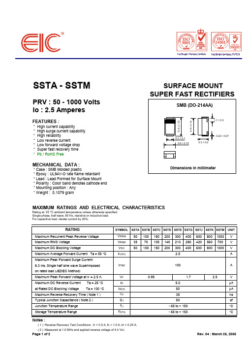
SSTA - SSTMSURFACE MOUNT SUPER FAST RECTIFIERSPRV : 50 - 1000 Volts Io : 2.5 AmperesFEATURES :* High current capability* High surge current capability * High reliability* Low reverse current* Low forward voltage drop * Super fast recovery time * Pb / RoHS FreeMECHANICAL DATA :* Case : SMB Molded plastic* Epoxy : UL94V-O rate flame retardant * Lead : Lead Formed for Surface Mount * Polarity : Color band denotes cathode end * Mounting position : Any * Weight : 0.1079 gramMAXIMUM RATINGS AND ELECTRICAL CHARACTERISTICSRating at 25 °C ambient temperature unless otherwise specified.Single phase, half wave, 60 Hz, resistive or inductive load. For capacitive load, derate current by 20%.SYMBOL SSTA SSTB SSTC SSTD SSTE SSTG SSTJ SSTK SSTM UNITMaximum Recurrent Peak Reverse Voltage V RRM 501001502003004006008001000V Maximum RMS Voltage V RMS 3570105140210280420560700V Maximum DC Blocking VoltageV DC 501001502003004006008001000V Maximum Average Forward Current Ta = 55 °C I F(AV) 2.5A Maximum Peak Forward Surge Current 8.3 ms. Single half sine wave Superimposed on rated load (JEDEC Method)Maximum Peak Forward Voltage at I F = 2.5 A.V F 0.95V Maximum DC Reverse Current Ta = 25 °C I R 5.0µA at Rated DC Blocking Voltage Ta = 100 °C I R(H)50µA Maximum Reverse Recovery Time ( Note 1 )Trr35ns Typical Junction Capacitance ( Note 2 )C J 50pf Junction Temperature Range T J - 65 to + 150°C Storage Temperature RangeT STG- 65 to + 150°CNotes :( 1 ) Reverse Recovery Test Conditions : IF = 0.5 A, IR= 1.0 A, Irr = 0.25 A. ( 2 ) Measured at 1.0 MHz and applied reverse voltage of 4.0 V DCPage 1 of 2Rev. 04 : March 25, 2005A1.72.5RATINGI FSM 100Page 2 of 2Rev. 04 : March 25, 2005。
SST单片机中文教程
· 兼容 80C51 系列,内置超级 FLASH 存储器的单片机 · SST89E5XXRD
工作电压 VDD=4.5~5.5V 5 伏工作电压时 0~40MHz 的频率范围 · SST89V5XXRD 工作电压 VDD=2.7~3.6V 在 3 伏工作电压下,原厂保证 0~25 MHz 的工作频率 ,实际最高可达 40MHz · 与现行的 80C52 列单片机硬件 PIN-TO-PIN 完全兼容,软件、开发工具也完全 兼容 · 1K*8 的内部 RAM(256Bytes+768Bytes,可放心使用 C 语言编程) · 两块超级 FLASH EEPROM —SST89E516RD/SST89V516RD:64K*8 的基本存储块和 8K*8 的二级存储块
座等生产设备,又避免了因为人为因素的选错文件,程序泄密等弊端. 简单,安全,保密,易 于生产管理
4. 数据存储:非易失数据存储(可超过 64K),掉电后数据不丢失,片内数据存储更保密。 5. 应用灵活:内嵌两块小扇区(128 字节/扇区)的 FLASH 存储器,程序和数据存储空间充
分互补利用, 不作程序的空间,均可作为数据存储.突破了标准 51 单片机的程序与数据必 须分开和 64K 的极限.用户程序最大可达 72K,数据存储可超 64K.
频 率Hz 5V /E 3V /V
存储器
RAM 4 P
源 级 指针
检 狗速口 I
测
40M 33M 64K+8K 1KB 1ch+ 5ch 8 4 2 √ √ √ √ √ √
40M 33M 32K+8K 1KB 1ch+ 5ch 8 4 2 √ √ √ √ √ √
—帧错误检测 —自动地址识别 · 9 个中断源,四个中断优先级 · 看门狗定时器(Watchdog Timer, 缺省情况下不打开,用户不需要时可不使用) · 可编程计数阵列(PCA) 标准为每个机器周期 12 个时钟,器件可选择在每个机器周期 6 个时钟基础上加 倍 掉电检测(Brow-out 缺省为产生复位,也可设置为产生中断) · 降低 EMI 模式(通过 AUXR SFR 不允许 ALE 输出时钟) 以上三项确保了 SST 单片机的高抗干扰性,可直接取代 ATMEL 公司的单片机 · 四个 8 位 I/O 口(32 根输入输出线)
109级高强螺栓标准

109级高强螺栓标准高强螺栓是一种常用的紧固件,广泛应用于桥梁、建筑、机械设备等领域。
而109级高强螺栓是其中一种常见的规格,其标准对于确保工程质量和安全具有重要意义。
本文将对109级高强螺栓的标准进行介绍,以便相关领域的工程师和技术人员更好地了解和应用。
首先,109级高强螺栓的材料标准是十分关键的。
根据相关标准,109级高强螺栓的材料应为优质合金钢,其化学成分和机械性能需符合国家标准或行业标准的要求。
这些要求包括螺栓的拉伸强度、屈服强度、延伸率等指标,以确保在工程中承受较大载荷时不会出现断裂或变形的情况。
其次,109级高强螺栓的表面处理也是十分重要的一环。
通常情况下,高强螺栓会经过热处理和表面镀层等工艺,以提高其耐腐蚀性能和抗疲劳性能。
对于109级高强螺栓来说,其表面处理的要求更为严格,需要保证其在恶劣环境下依然能够保持良好的使用性能。
另外,螺栓的尺寸和螺纹标准也是109级高强螺栓标准的重要内容之一。
在工程实践中,螺栓的尺寸和螺纹必须与配合的螺母和螺栓孔相匹配,以确保其能够正确地安装和紧固。
因此,109级高强螺栓的尺寸公差、螺纹规格等方面的标准都需要严格执行,以保证其在工程中的可靠性和稳定性。
最后,对于109级高强螺栓的质量控制也是至关重要的。
在生产过程中,需要严格执行相关标准和规范,对材料、工艺、尺寸等进行全面的检测和控制,以确保产品质量符合标准要求。
同时,在使用过程中,需要对螺栓进行定期的检测和维护,以确保其在工程中的安全可靠性。
总的来说,109级高强螺栓标准涉及材料、表面处理、尺寸和螺纹标准、质量控制等多个方面,对于工程质量和安全具有重要意义。
只有严格执行相关标准和规范,才能确保109级高强螺栓在工程中发挥应有的作用,为工程的顺利进行提供保障。
希望本文能够帮助相关领域的工程师和技术人员更好地理解和应用109级高强螺栓标准,推动工程质量和安全水平的提升。
CSL109A
CSL109A数字式线路保护装置技术说明书( V 1.00 版)2000年10月1 概述 (1)2 主要技术数据 (1)3 结构 (4)4 硬件说明 (4)4.1 交流插件 (4)4.2 模数变换插件 (5)4.3 故障录波插件 (5)4.4 CPU插件 (6)4.5 继电器插件 (7)4.6 电源插件 (8)4.7 人机对话板 (8)4.8 选供的打印机接口和工程师站 (9)4.9 装置端子说明 (10)5 人机对话 (10)5.1 正常运行显示 (10)5.2 各种功能键 (12)6装置功能说明 (15)6.1启动元件 (15)6.2距离保护 (15)6.3和流保护 (17)6.4过流保护 (17)6.5手合加速回路 (17)6.6 PT断线 (17)6.7 CT断线 (17)6.8 故障处理软件流程 (17)6.9 与变电站综合自动化系统配合 (22)6.10 故障录波插件功能 (23)7 定值管理 (24)7.1 概述 (24)7.2 定值清单 (24)7.3 故障录波插件定值 (26)8 用户安装调试说明 (29)8.1 通电前检查 (29)8.2 装置通电检查 (30)8.2.1 直流稳压电源通电检查 (30)8.2.2 整机通电检查 (30)8.2.3 开入量检查 (30)8.2.4 零漂检查 (30)8.2.5 电流电压刻度检查 (30)8.2.6 定值输入 (31)8.2.7 开出传动试验 (31)8.3 模拟短路试验 (31)8.3.1 试验目的及项目 (31)8.3.2 试验注意事项 (31)8.4 耐压试验 (31)9 维护运行 (31)9.1 装置的投运 (31)9.2 装置的运行 (31)9.3 保护的动作信号及报告 (32)9.4 报告信息 (32)9.4.1正常显示信息 (32)9.4.2CSL109A保护动作及告警信息 (32)9.5 其它注意事项 (33)10 维修指南 (34)11 贮存 (34)* 订货须知 (34)** 附图 (35)附图1 面板布置图 (36)附图2 CSL109A装置插件位置图 (37)附图3 各插件联系简图 (38)附图4 交流插件原理图 (39)附图5 VFC芯片电压频率特性 (40)附图6 模数变换插件原理图 (41)附图7 继电器插件原理图 (42)附图8 电源插件原理图 (43)附图9 CSL109A背板端子图(非综自) (44)附图10CSL109A背板端子图(综自硬压板) (45)附图11 CSL109A背板端子图(综自软压板) (46)附图12CSL109A背板连线图 (47)附图13CPU插件原理图 (48)附图14 -1MMI插件原理图 (49)附图14-2 MMI插件原理图 (50)附图15-1 录波插件原理图 (51)附图15-2 录波插件原理图 (52)1.概述本装置系由微型计算机构成的以相间距离保护和和流保护为核心的成套线路保护装置,主要适用于220KV两相供电的电铁线路。
SST175中文资料
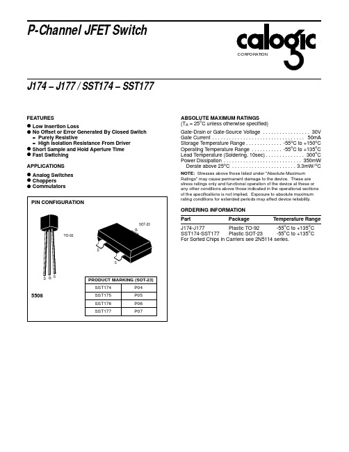
APPLICATIONS
ORDERING INFORMATION Part
SOT-23 G
TO-92
Package
Temperature Range
J174-J177 Plastic TO-92 -55oC to +135oC SST174-SST177 Plastic SOT-23 -55oC to +135oC For Sorted Chips in Carriers see 2N5114 series.
rDS(on)
85
125
250
300
VGS = 0, VDS = -0.VDS = 0, VGS = 10V
Csg(off)
5.5
5.5
5.5
5.5
pF
f = 1MHz (Note 3)
Cdg(on) + Csg(on)
32
32
32
32
VDS = VGS = 0
SYMBOL PARAMETER Gate Reverse Current (Note 1) Gate Source Cutoff Voltage Gate Source Breakdown Voltage Drain Saturation Current (Note 2) Drain Cutoff Current (Note 1) Drain-Source ON Resistance Drain-Gate OFF Capacitance Source-Gate OFF Capacitance Drain-Gate Plus Source Gate ON Capacitance Turn On Delay Time Rise Time Turn Off Delay Time Fall Time 5.5 5 J174 J175 J176 J177 UNITS TEST CONDITIONS MIN TYP MAX MIN TYP MAX MIN TYP MAX MIN TYP MAX IGSS 1 1 1 1 nA VDS = 0, VGS = 20V
ASTM C109 C109M-02

Designation:C109/C109M–02Standard Test Method forCompressive Strength of Hydraulic Cement Mortars(Using2-in.or[50-mm]Cube Specimens)1This standard is issued under thefixed designation C109/C109M;the number immediately following the designation indicates the year of original adoption or,in the case of revision,the year of last revision.A number in parentheses indicates the year of last reapproval.A superscript epsilon(e)indicates an editorial change since the last revision or reapproval.This standard has been approved for use by agencies of the Department of Defense.1.Scope*1.1This test method covers determination of the compres-sive strength of hydraulic cement mortars,using2-in.or [50-mm]cube specimens.N OTE1—Test Method C349provides an alternative procedure for this determination(not to be used for acceptance tests).1.2This test method covers the application of the test using either inch-pound or SI units.The values stated in either system shall be regarded separately as standard.Within the text,the SI units are shown in brackets.The values stated in each system are not exact equivalents;therefore,each system shall be used independently of the bining values from the two systems may result in nonconformance with the specification.1.3Values in SI units shall be obtained by measurement in SI units or by appropriate conversion,using the Rules for Conversion and Rounding given in Standard IEEE/ASTM SI 10,of measurements made in other units.1.4This standard does not purport to address all of the safety concerns,if any,associated with its use.It is the responsibility of the user of this standard to establish appro-priate safety and health practices and determine the applica-bility of regulatory limitations prior to use.(Warning—Fresh hydraulic cementitious mixtures are caustic and may cause chemical burns to skin and tissue upon prolonged exposure.2)2.Referenced Documents2.1ASTM Standards:C230Specification for Flow Table for Use in Tests of Hydraulic Cement3C305Practice for Mechanical Mixing of Hydraulic Cement Pastes and Mortars of Plastic Consistency3C349Test Method for Compressive Strength of Hydraulic Cement Mortars(Using Portions of Prisms Broken in Flexure)3C511Specification for Moist Cabinets,Moist Rooms and Water Storage Tanks Used in the Testing of Hydraulic Cements and Concretes3C670Practice for Preparing Precision and Bias Statements for Test Methods for Construction Materials4C778Specification for Standard Sand3C1005Specification for Reference Masses and Devices for Determining Mass and V olume3C1437Test Method for Flow of Hydraulic Cement Mor-tar3IEEE/ASTM SI10Standard for Use of the International System of Units(SI):The Modern Metric System53.Summary of Test Method3.1The mortar used consists of1part cement and2.75parts of sand proportioned by mass.Portland or air-entraining portland cements are mixed at specified water/cement ratios. Water content for other cements is that sufficient to obtain a flow of11065in25drops of theflow table.Two-inch or [50-mm]test cubes are compacted by tamping in two layers. The cubes are cured one day in the molds and stripped and immersed in lime water until tested.4.Significance and Use4.1This test method provides a means of determining the compressive strength of hydraulic cement and other mortars and results may be used to determine compliance with speci-fications.Further,this test method is referenced by numerous other specifications and test methods.Caution must be exer-cised in using the results of this test method to predict the strength of concretes.5.Apparatus5.1Weights and Weighing Devices,shall conform to the requirements of Specification C1005.The weighing device shall be evaluated for precision and bias at a total load of2000 g.5.2Glass Graduates,of suitable capacities(preferably large enough to measure the mixing water in a single operation)to1This test method is under the jurisdiction of ASTM Committee C01on Cement and is the direct responsibility of Subcommittee C01.27on Strength.Current edition approved June10,2002.Published August2002.Originally published as C109–st previous edition C109/C109M–01.2See the section on Safety,Manual of Cement Testing,Annual Book of ASTMStandards,V ol04.01.3Annual Book of ASTM Standards,V ol04.01.4Annual Book of ASTM Standards,V ol04.02.5Annual Book of ASTM Standards,V ol14.04. 1*A Summary of Changes section appears at the end of this standard. Copyright©ASTM International,100Barr Harbor Drive,PO Box C700,West Conshohocken,PA19428-2959,United States.deliver the indicated volume at 20°C.The permissible variation shall be 62mL.These graduates shall be subdivided to at least 5mL,except that the graduation lines may be omitted for the lowest 10mL for a 250-mL graduate and for the lowest 25mL of a 500-mL graduate.The main graduation lines shall be circles and shall be numbered.The least graduations shall extend at least one seventh of the way around,and intermediate graduations shall extend at least one fifth of the way around.5.3Specimen Molds ,for the 2-in.or [50-mm]cube speci-mens shall be tight fitting.The molds shall have not more than three cube compartments and shall be separable into not more than two parts.The parts of the molds when assembled shall be positively held together.The molds shall be made of hard metal not attacked by the cement mortar.For new molds the Rockwell hardness number of the metal shall be not less than 55HRB.The sides of the molds shall be sufficiently rigid to prevent spreading or warping.The interior faces of the molds shall be plane surfaces and shall conform to the tolerances of Table 1.5.4Mixer,Bowl and Paddle ,an electrically driven mechani-cal mixer of the type equipped with paddle and mixing bowl,as specified in Practice C 305.5.5Flow Table and Flow Mold ,conforming to the require-ments of Specification C 230.5.6Tamper ,a nonabsorptive,nonabrasive,nonbrittle mate-rial such as a rubber compound having a Shore A durometer hardness of 80610or seasoned oak wood rendered nonab-sorptive by immersion for 15min in paraffin at approximately 392°F or [200°C],shall have a cross section of about 1⁄2by 1in.or [13by 25mm]and a convenient length of about 5to 6in.or [120to 150mm].The tamping face shall be flat and at right angles to the length of the tamper.5.7Trowel ,having a steel blade 4to 6in.[100to 150mm]in length,with straight edges.5.8Moist Cabinet or Room,conforming to the require-ments of Specification C 511.5.9Testing Machine ,either the hydraulic or the screw type,with sufficient opening between the upper bearing surface and the lower bearing surface of the machine to permit the use of verifying apparatus.The load applied to the test specimen shall be indicated with an accuracy of 61.0%.If the load applied by the compression machine is registered on a dial,the dial shall be provided with a graduated scale that can be read to at least the nearest 0.1%of the full scale load (Note 2).The dial shall be readable within 1%of the indicated load at any given load level within the loading range.In no case shall the loading range of a dial be considered to include loads below the value that is 100times the smallest change of load that can be read on the scale.The scale shall be provided with a graduation lineequal to zero and so numbered.The dial pointer shall be of sufficient length to reach the graduation marks;the width of the end of the pointer shall not exceed the clear distance between the smallest graduations.Each dial shall be equipped with a zero adjustment that is easily accessible from the outside of the dial case,and with a suitable device that at all times until reset,will indicate to within 1%accuracy the maximum load applied to the specimen.5.9.1If the testing machine load is indicated in digital form,the numerical display must be large enough to be easily read.The numerical increment must be equal to or less than 0.10%of the full scale load of a given loading range.In no case shall the verified loading range include loads less than the minimum numerical increment multiplied by 100.The accuracy of the indicated load must be within 1.0%for any value displayed within the verified loading range.Provision must be made for adjusting to indicate true zero at zero load.There shall be provided a maximum load indicator that at all times until reset will indicate within 1%system accuracy the maximum load applied to the specimen.N OTE 2—As close as can be read is considered 1⁄50in.or [0.5mm]along the arc described by the end of the pointer.Also,one half of the scale interval is about as close as can reasonably be read when the spacing on the load indicating mechanism is between 1⁄25in.or [1mm]and 1⁄16in.or [1.6mm].When the spacing is between 1⁄16in.or [1.6mm]and 1⁄8in.or [3.2mm],one third of the scale interval can be read with reasonable certainty.When the spacing is 1⁄8in.or [3.2mm]or more,one fourth of the scale interval can be read with reasonable certainty.5.9.2The upper bearing shall be a spherically seated,hardened metal block firmly attached at the center of the upper head of the machine.The center of the sphere shall lie at the center of the surface of the block in contact with the specimen.The block shall be closely held in its spherical seat,but shall be free to tilt in any direction.The diagonal or diameter (Note 3)of the bearing surface shall be only slightly greater than the diagonal of the face of the 2-in.or [50-mm]cube in order to facilitate accurate centering of the specimen.A hardened metal bearing block shall be used beneath the specimen to minimize wear of the lower platen of the machine.The bearing block surfaces intended for contact with the specimen shall have a Rockwell hardness number not less than 60HRC.These surfaces shall not depart from plane surfaces by more than 0.0005in.or [0.013mm]when the blocks are new and shall be maintained within a permissible variation of 0.001in.or [0.025mm].N OTE 3—A diameter of 31⁄8in.or [79.4mm],is satisfactory,provided that the lower bearing block has a diameter slightly greater than the diagonal of the face of the 2-in.or [50-mm]cube but not more than 2.9in.or [74mm],and is centered with respect to the upper bearing block andTABLE 1Permissible Variations of Specimen Molds2-in.Cube Molds[50-mm]Cube MoldsParameterNew In Use NewIn UsePlaneness of sides<0.001in.<0.002in.[<0.025mm][<0.05mm]Distance between opposite sides 2in.60.0052in.60.02[50mm 60.13mm][50mm 60.50mm]Height of each compartment 2in.+0.01in.2in.+0.01in.[50mm +0.25mm [50mm +0.25mm to −0.005in.to −0.015in.to −0.13mm]to −0.38mm]Angle between adjacent faces A9060.5°9060.5°9060.5°9060.5°AMeasured at points slightly removed from the intersection.Measured separately for each compartment between all the interior faces and the adjacent face and between interior faces and top and bottom planes of themold.held in position by suitable means.6.Materials6.1Graded Standard Sand:6.1.1The sand(Note4)used for making test specimens shall be natural silica sand conforming to the requirements for graded standard sand in Specification C778.N OTE4—Segregation of Graded Sand—The graded standard sand should be handled in such a manner as to prevent segregation,since variations in the grading of the sand cause variations in the consistency of the mortar.In emptying bins or sacks,care should be exercised to prevent the formation of mounds of sand or craters in the sand,down the slopes of which the coarser particles will roll.Bins should be of sufficient size to permit these precautions.Devices for drawing the sand from bins by gravity should not be used.7.Temperature and Humidity7.1Temperature—The temperature of the air in the vicinity of the mixing slab,the dry materials,molds,base plates,and mixing bowl,shall be maintained between73.565.5°F or [23.063.0°C].The temperature of the mixing water,moist closet or moist room,and water in the storage tank shall be set at73.563.5°F or[2362°C].7.2Humidity—The relative humidity of the laboratory shall be not less than50%.The moist closet or moist room shall conform to the requirements of Specification C511.8.Test Specimens8.1Make two or three specimens from a batch of mortar for each period of test or test age.9.Preparation of Specimen Molds9.1Apply a thin coating of release agent to the interior faces of the mold and non-absorptive base plates.Apply oils and greases using an impregnated cloth or other suitable means. Wipe the mold faces and the base plate with a cloth as necessary to remove any excess release agent and to achieve a thin,even coating on the interior surfaces.When using an aerosol lubricant,spray the release agent directly onto the mold faces and base plate from a distance of6to8in.or[150to200 mm]to achieve complete coverage.After spraying,wipe the surface with a cloth as necessary to remove any excess aerosol lubricant.The residue coating should be just sufficient to allow a distinctfinger print to remain following lightfinger pressure (Note5).9.2Seal the surfaces where the halves of the mold join by applying a coating of light cup grease such as petrolatum.The amount should be sufficient to extrude slightly when the two halves are tightened together.Remove any excess grease witha cloth.9.3After placing the mold on its base plate(and attaching, if clamp-type)carefully remove with a dry cloth any excess oil or grease from the surface of the mold and the base plate to which watertight sealant is to be applied.As a sealant,use paraffin,microcrystalline wax,or a mixture of three parts paraffin tofive parts rosin by mass.Liquify the sealant by heating between230and248°F or[110and120°C].Effect a watertight seal by applying the liquefied sealant at the outside contact lines between the mold and its base plate.N OTE5—Because aerosol lubricants evaporate,molds should be checked for a sufficient coating of lubricant immediately prior to use.If an extended period of time has elapsed since treatment,retreatment may be necessary.N OTE6—Watertight Molds—The mixture of paraffin and rosin specified for sealing the joints between molds and base plates may be found difficult to remove when molds are being e of straight paraffin is permissible if a watertight joint is secured,but due to the low strength of paraffin it should be used only when the mold is not held to the base plate by the paraffin alone.A watertight joint may be secured with paraffin alone by slightly warming the mold and base plate before brushing the joint. Molds so treated should be allowed to return to the specified temperature before use.10.Procedure10.1Composition of Mortars:10.1.1The proportions of materials for the standard mortar shall be one part of cement to2.75parts of graded standard sand by e a water-cement ratio of0.485for all portland cements and0.460for all air-entraining portland cements.The amount of mixing water for other than portland and air-entraining portland cements shall be such as to produce aflow of11065as determined in accordance with10.3and shall be expressed as weight percent of cement.10.1.2The quantities of materials to be mixed at one time in the batch of mortar for making six and nine test specimens shall be as follows:Number of Specimens69 Cement,gSand,gWater,mL50013757402035Portland(0.485)Air-entraining portland(0.460)242230359340 Other(toflow of11065)...... 10.2Preparation of Mortar:10.2.1Mechanically mix in accordance with the procedure given in Practice C305.10.3Determination of Flow:10.3.1Determineflow in accordance with procedure given in Test Method C1437.10.3.2For portland and air-entraining portland cements, merely record theflow.10.3.3In the case of cements other than portland or air-entraining portland cements,make trial mortars with varying percentages of water until the specifiedflow is obtained.Make each trial with fresh mortar.10.4Molding Test Specimens:10.4.1Immediately following completion of theflow test, return the mortar from theflow table to the mixing bowl. Quickly scrape the bowl sides and transfer into the batch the mortar that may have collected on the side of the bowl and then remix the entire batch15s at medium speed.Upon completion of mixing,the mixing paddle shall be shaken to remove excess mortar into the mixing bowl.10.4.2When a duplicate batch is to be made immediately for additional specimens,theflow test may be omitted and the mortar allowed to stand in the mixing bowl90s without covering.During the last15s of this interval,quickly scrape the bowl sides and transfer into the batch the mortar that may have collected on the side of the bowl.Then remix for15s at mediumspeed.10.4.3Start molding the specimens within a total elapsed time of not more than 2min and 30s after completion of the original mixing of the mortar batch.Place a layer of mortar about 1in.or [25mm](approximately one half of the depth of the mold)in all of the cube compartments.Tamp the mortar in each cube compartment 32times in about 10s in 4rounds,each round to be at right angles to the other and consisting of eight adjoining strokes over the surface of the specimen,as illustrated in Fig. 1.The tamping pressure shall be just sufficient to ensure uniform filling of the molds.The 4rounds of tamping (32strokes)of the mortar shall be completed in one cube before going to the next.When the tamping of the first layer in all of the cube compartments is completed,fill the compartments with the remaining mortar and then tamp as specified for the first layer.During tamping of the second layer,bring in the mortar forced out onto the tops of the molds after each round of tamping by means of the gloved fingers and the tamper upon completion of each round and before starting the next round of tamping.On completion of the tamping,the tops of all cubes should extend slightly above the tops of the molds.Bring in the mortar that has been forced out onto the tops of the molds with a trowel and smooth off the cubes by drawing the flat side of the trowel (with the leading edge slightly raised)once across the top of each cube at right angles to the length of the mold.Then,for the purpose of leveling the mortar and making the mortar that protrudes above the top of the mold of more uniform thickness,draw the flat side of the trowel (with the leading edge slightly raised)lightly once along the length of the mold.Cut off the mortar to a plane surface flush with the top of the mold by drawing the straight edge of the trowel (held nearly perpendicular to the mold)with a sawing motion over the length of the mold.10.5Storage of Test Specimens —Immediately upon completion of molding,place the test specimens in the moist closet or moist room.Keep all test specimens,immediately after molding,in the molds on the base plates in the moist closet or moist room from 20to 72h with their upper surfaces exposed to the moist air but protected from dripping water.If the specimens are removed from the molds before 24h,keep them on the shelves of the moist closet or moist room until they are 24-h old,and then immerse the specimens,except those for the 24-h test,in saturated lime water in storage tanks con-structed of noncorroding materials.Keep the storage water clean by changing as required.10.6Determination of Compressive Strength :10.6.1Test the specimens immediately after their removal from the moist closet in the case of 24-h specimens,and from storage water in the case of all other specimens.All testspecimens for a given test age shall be broken within the permissible tolerance prescribed as follows:Test Age Permissible Tolerance24h 61⁄2h 3days 61h 7days 63h 28days612hIf more than one specimen at a time is removed from the moist closet for the 24-h tests,keep these specimens covered with a damp cloth until time of testing.If more than one specimen at a time is removed from the storage water for testing,keep these specimens in water at a temperature of 73.56 3.5°F or [2362°C]and of sufficient depth to completely immerse each specimen until time of testing.10.6.2Wipe each specimen to a surface-dry condition,and remove any loose sand grains or incrustations from the faces that will be in contact with the bearing blocks of the testing machine.Check these faces by applying a straightedge (Note 7).If there is appreciable curvature,grind the face or faces to plane surfaces or discard the specimen.A periodic check of the cross-sectional area of the specimens should be made.N OTE 7—Specimen Faces—Results much lower than the true strength will be obtained by loading faces of the cube specimen that are not truly plane surfaces.Therefore,it is essential that specimen molds be kept scrupulously clean,as otherwise,large irregularities in the surfaces will occur.Instruments for cleaning molds should always be softer than the metal in the molds to prevent wear.In case grinding specimen faces is necessary,it can be accomplished best by rubbing the specimen on a sheet of fine emery paper or cloth glued to a plane surface,using only a moderate pressure.Such grinding is tedious for more than a few thousandths of an inch (hundredths of a millimetre);where more than this is found necessary,it is recommended that the specimen be discarded.10.6.3Apply the load to specimen faces that were in contact with the true plane surfaces of the mold.Carefully place the specimen in the testing machine below the center of the upper bearing block.Prior to the testing of each cube,it shall be ascertained that the spherically seated block is free to e no cushioning or bedding materials.Bring the spherically seated block into uniform contact with the surface of the specimen.Apply the load rate at a relative rate of movement between the upper and lower platens corresponding to a loading on the specimen with the range of 200to 400lbs/s [900to 1800N/s].Obtain this designated rate of movement of the platen during the first half of the anticipated maximum load and make no adjustment in the rate of movement of the platen in the latter half of the loading especially while the cube is yielding before failure.N OTE 8—It is advisable to apply only a very light coating of a good quality,light mineral oil to the spherical seat of the upper platen.11.Calculation11.1Record the total maximum load indicated by the testing machine,and calculate the compressive strength as follows:fm 5P /A(1)where:fm =compressive strength in psi or[MPa],FIG.1Order of Tamping in Molding of TestSpecimensP=total maximum load in lbf or[N],andA=area of loaded surface in2or[mm2].Either2-in.or[50-mm]cube specimens may be used for the determination of compressive strength,whether inch-pound or SI units are used.However,consistent units for load and area must be used to calculate strength in the units selected.If the cross-sectional area of a specimen varies more than1.5%from the nominal,use the actual area for the calculation of the compressive strength.The compressive strength of all accept-able test specimens(see Section12)made from the same sample and tested at the same period shall be averaged and reported to the nearest10psi[0.1MPa].12.Report12.1Report theflow to the nearest1%and the water used to the nearest0.1%.Average compressive strength of all specimens from the same sample shall be reported to the nearest10psi[0.1MPa].13.Faulty Specimens and Retests13.1In determining the compressive strength,do not con-sider specimens that are manifestly faulty.13.2The maximum permissible range between specimens from the same mortar batch,at the same test age is8.7%of the average when three cubes represent a test age and7.6%when two cubes represent a test age(Note9).N OTE9—The probability of exceeding these ranges is1in100when the within-batch coefficient of variation is2.1%.The2.1%is an average for laboratories participating in the portland cement and masonry cement reference sample programs of the Cement and Concrete Reference Laboratory.13.3If the range of three specimens exceeds the maximum in13.2,discard the result which differs most from the average and check the range of the remaining two specimens.Make a retest of the sample if less than two specimens remain after disgarding faulty specimens or disgarding tests that fail to comply with the maximum permissible range of two speci-mens.N OTE10—Reliable strength results depend upon careful observance of all of the specified requirements and procedures.Erratic results at a given test period indicate that some of the requirements and procedures have not been carefully observed;for example,those covering the testing of the specimens as prescribed in10.6.2and10.6.3.Improper centering of specimens resulting in oblique fractures or lateral movement of one of the heads of the testing machine during loading will cause lower strength results.14.Precision and Bias14.1Precision—The precision statements for this test method are listed in Table2and are based on results from the Cement and Concrete Reference Laboratory Reference Sample Program.They are developed from data where a test result is the average of compressive strength tests of three cubes molded from a single batch of mortar and tested at the same age.A significant change in precision will not be noted when a test result is the average of two cubes rather than three. 14.2These precision statements are applicable to mortars made with cements mixed,and tested at the ages as noted.The appropriate limits are likely,somewhat larger for tests at younger ages and slightly smaller for tests at older ages. 14.3Bias—The procedure in this test method has no bias because the value of compressive strength is defined in terms of the test method.15.Keywords15.1compressive strength;hydraulic cement mortar;hy-draulic cement strength;mortar strength;strengthTABLE2PrecisionTest Age,DaysCoefficientof Variation1s%AAcceptableRange of TestResults d2s%A Portland CementsConstant water-cementratio:Single-lab374.03.611.310.2Av 3.810.7Multi-lab376.86.419.218.1Av 6.618.7 Blended CementsConstantflow mortar:Single-lab37284.03.83.411.310.79.6Av 3.810.7Multi-lab37287.87.67.422.121.520.9Av7.621.5 Masonry CementsConstantflow mortar:Single-lab7287.97.522.321.2Av7.721.8Multi-lab72811.812.033.433.9Av11.933.7A These numbers represent,respectively,the(1s%)and(d2s%)limits as described in Practice C670.SUMMARY OF CHANGESThis section identifies the location of changes to this test method that have been incorporated since the lastissue,C109/C109M–01.(1)Temperatures were revised in7.1.(2)A warning statement was added to1.4,with accompanyingfootnote.ASTM International takes no position respecting the validity of any patent rights asserted in connection with any item mentioned in this ers of this standard are expressly advised that determination of the validity of any such patent rights,and the riskof infringement of such rights,are entirely their own responsibility.This standard is subject to revision at any time by the responsible technical committee and must be reviewed everyfive years and if not revised,either reapproved or withdrawn.Your comments are invited either for revision of this standard or for additional standardsand should be addressed to ASTM International Headquarters.Your comments will receive careful consideration at a meeting of theresponsible technical committee,which you may attend.If you feel that your comments have not received a fair hearing you shouldmake your views known to the ASTM Committee on Standards,at the address shown below.This standard is copyrighted by ASTM International,100Barr Harbor Drive,PO Box C700,West Conshohocken,PA19428-2959, United States.Individual reprints(single or multiple copies)of this standard may be obtained by contacting ASTM at the aboveaddress or at610-832-9585(phone),610-832-9555(fax),or service@(e-mail);or through the ASTM website().。
LM109资料
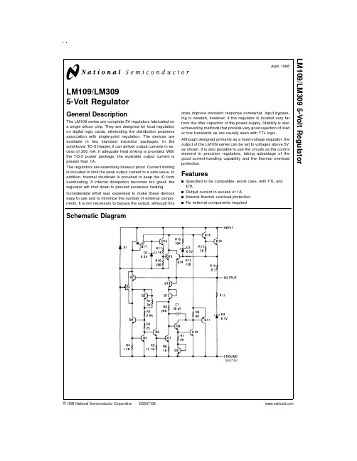
LM109/LM3095-Volt RegulatorGeneral DescriptionThe LM109series are complete 5V regulators fabricated on a single silicon chip.They are designed for local regulation on digital logic cards,eliminating the distribution problems association with single-point regulation.The devices are available in two standard transistor packages.In the solid-kovar TO-5header,it can deliver output currents in ex-cess of 200mA,if adequate heat sinking is provided.With the TO-3power package,the available output current is greater than 1A.The regulators are essentially blowout proof.Current limiting is included to limit the peak output current to a safe value.In addition,thermal shutdown is provided to keep the IC from overheating.If internal dissipation becomes too great,the regulator will shut down to prevent excessive heating.Considerable effort was expended to make these devices easy to use and to minimize the number of external compo-nents.It is not necessary to bypass the output,although thisdoes improve transient response somewhat.Input bypass-ing is needed,however,if the regulator is located very far from the filter capacitor of the power supply.Stability is also achieved by methods that provide very good rejection of load or line transients as are usually seen with TTL logic.Although designed primarily as a fixed-voltage regulator,the output of the LM109series can be set to voltages above 5V,as shown.It is also possible to use the circuits as the control element in precision regulators,taking advantage of the good current-handling capability and the thermal overload protection.Featuresn Specified to be compatible,worst case,with TTL and DTLn Output current in excess of 1An Internal thermal overload protection n No external components requiredSchematic DiagramDS007138-1April 1998LM109/LM3095-Volt Regulator©1999National Semiconductor Corporation Absolute Maximum Ratings (Note 1)If Military/Aerospace specified devices are required,please contact the National Semiconductor Sales Office/Distributors for availability and specifications.Input Voltage35VPower DissipationInternally LimitedOperating Junction Temperature Range LM109−55˚C to +150˚C LM3090˚C to +125˚C Storage Temperature Range −65˚C to +150˚CLead Temperature (Soldering,10sec.)300˚CElectrical Characteristics (Note 2)ParameterConditionsLM109LM309UnitsMinTyp Max Min Typ Max Output Voltage T j =25˚C 4.75.05 5.3 4.85.05 5.2V Line Regulation T j =25˚C 4.0504.050mV 7.10V ≤V IN ≤25V Load RegulationT j =25˚CTO-39Package 5mA ≤I OUT ≤0.5A 15501550mV TO-3Package5mA ≤I OUT ≤1.5A 1510015100mV Output Voltage7.40V ≤V IN ≤25V, 4.65.44.755.25V5mA ≤I OUT ≤I MAX ,P <P MAXQuiescent Current 7.40V ≤V IN ≤25V 5.210 5.210mA Quiescent Current Change 7.40V ≤V IN ≤25V 0.50.5mA 5mA ≤I OUT ≤I MAX 0.80.8mA Output Noise Voltage T A =25˚C4040µV10Hz ≤f ≤100kHzLong Term Stability 1020mV Ripple Rejection T j =25˚C 5050dBThermal Resistance,(Note 3)Junction to CaseTO-39Package 1515˚C/W TO-3Package2.52.5˚C/WNote 1:“Absolute Maximum Ratings”indicate limits beyond which damage to the device may occur.Operating Ratings indicate conditions for which the device is functional,but do not guarantee specific performance limits.Note 2:Unless otherwise specified,these specifications apply −55˚C ≤T j ≤+150˚C for the LM109and 0˚C ≤T j ≤+125˚C for the LM309;V IN =10V;and I OUT =0.1A for the TO-39package or I OUT =0.5A for the TO-3package.For the TO-39package,I MAX =0.2A and P MAX =2.0W.For the TO-3package,I MAX =1.0A and P MAX =20W.Note 3:Without a heat sink,the thermal resistance of the TO-39package is about 150˚C/W,while that of the TO-3package is approximately 35˚C/W.With a heat sink,the effective thermal resistance can only approach the values specified,depending on the efficiency of the sink.Note 4:Refer to RETS109H drawing for LM109H or RETS109K drawing for LM109K military specifications.Connection DiagramsMetal Can PackagesDS007138-33Order Number LM109H,LM109H/883or LM309HSee NS Package Number H03ADS007138-34Order Number LM109K STEEL orLM309K STEELSee NS Package Number K02A Order Number LM109K/883See NS Package Number K02C2Application Hints1.Bypass the input of the LM109to ground with≥0.2µFceramic or solid tantalum capacitor if main filter capaci-tor is more than4inches away.2.Avoid insertion of regulator into“live”socket if inputvoltage is greater than10V.The output will rise to within 2V of the unregulated input if the ground pin does not make contact,possibly damaging the load.The LM109 may also be damaged if a large output capacitor is charged up,then discharged through the internal clamp zener when the ground pin makes contact.3.The output clamp zener is designed to absorb tran-sients only.It will not clamp the output effectively if a fail-ure occurs in the internal power transistor structure.Ze-ner dynamic impedance is≈4Ω.Continuous RMS current into the zener should not exceed0.5A.4.Paralleling of LM109s for higher output current is notrecommended.Current sharing will be almost nonexist-ent,leading to a current limit mode operation for devices with the highest initial output voltage.The current limit devices may also heat up to the thermal shutdown point (≈175˚C).Long term reliability cannot be guaranteed under these conditions.5.Preventing latchoff for loads connected to negativevoltage:If the output of the LM109is pulled negative by a high cur-rent supply so that the output pin is more than0.5V negative with respect to the ground pin,the LM109can latch off.This can be prevented by clamping the ground pin to the output pin with a germanium or Schottky diode as shown.A silicon diode(1N4001)at the output is also needed to keep the positive output from being pulled too far negative.The10Ωresistor will raise+V OUT by≈0.05V.Crowbar Overvoltage Protection Typical Performance Characteristics DS007138-7Input CrowbarDS007138-8Output CrowbarDS007138-9*Zener is internal to LM109.**Q1must be able to withstand7A continuous current if fusing is not used at regulator input.LM109bond wires will fuse at currents above7A.†Q2is selected for surge capability.Consideration must be given to filter capacitor size,transformer impedance,and fuse blowing time.††Trip point is≈7.5V.Maximum AveragePower Dissipation(LM109K)DS007138-16Maximum AveragePower Dissipation(LM309K)DS007138-17Output ImpedanceDS007138-18 3Typical Performance Characteristics(Continued)Maximum AveragePower Dissipation (LM109H)DS007138-19Maximum AveragePower Dissipation (LM309H)DS007138-20Ripple RejectionDS007138-21Current LimitCharacteristics (Note 5)DS007138-22Thermally Induced Output Voltage VariationDS007138-23Ripple RejectionDS007138-24Note 5:Current limiting foldback characteristics are determined by input output differential,not by output voltage.Input-Output Differential (V)DS007138-25Output Voltage (V)DS007138-26Output Voltage (V)DS007138-27 4Typical Performance Characteristics(Continued)Typical ApplicationsQuiescent CurrentDS007138-28Quiescent CurrentDS007138-29Output Voltage NoiseDS007138-30Line Transient Response DS007138-31Load Transient ResponseDS007138-32Fixed 5V RegulatorDS007138-2*Required if regulator is located more than 4"from power supply filter capacitor.†Although no output capacitor is needed for stability,it does improve transient response.C2should be used whenever long wires are used to connect to the load,or when transient response is critical.Note:Pin 3electrically connected to case.Adjustable Output RegulatorDS007138-45Typical Applications(Continued)High Stability Regulator*DS007138-5*Regulation better than0.01%,load,line and temperature,can be obtained.†Determines zener current.May be adjusted to minimize thermal drift.‡Solid tantalum.Current RegulatorDS007138-6 *Determines output current.If wirewound resistor is used,bypass with0.1µF.6Physical Dimensions inches(millimeters)unless otherwise notedMetal Can Package(H)Order Number LM109H,LM109H/883or LM309HNS Package Number H03AMetal Can Package(K)Order Number LM109K STEEL,LM309K STEELNS Package Number K02A7Physical Dimensionsinches (millimeters)unless otherwise noted (Continued)LIFE SUPPORT POLICYNATIONAL’S PRODUCTS ARE NOT AUTHORIZED FOR USE AS CRITICAL COMPONENTS IN LIFE SUPPORT DE-VICES OR SYSTEMS WITHOUT THE EXPRESS WRITTEN APPROVAL OF THE PRESIDENT OF NATIONAL SEMI-CONDUCTOR CORPORATION.As used herein:1.Life support devices or systems are devices or sys-tems which,(a)are intended for surgical implant intothe body,or (b)support or sustain life,and whose fail-ure to perform when properly used in accordancewith instructions for use provided in the labeling,can be reasonably expected to result in a significant injury to the user.2.A critical component is any component of a life support device or system whose failure to perform can be rea-sonably expected to cause the failure of the life support device or system,or to affect its safety or effectiveness.National Semiconductor Corporation AmericasTel:1-800-272-9959Fax:1-800-737-7018Email:support@National Semiconductor EuropeFax:+49(0)180-5308586Email:europe.support@Deutsch Tel:+49(0)180-5308585English Tel:+49(0)180-5327832Français Tel:+49(0)180-5329358Italiano Tel:+49(0)180-5341680National Semiconductor Asia Pacific Customer Response Group Tel:65-2544466Fax:65-2504466Email:sea.support@National Semiconductor Japan Ltd.Tel:81-3-5639-7560Fax:81-3-5639-7507Metal Can Package (K)Mil-Aero ProductOrder Number LM109K/883NS Package Number K02CL M 109/L M 3095-V o l t R e g u l a t o rNational does not assume any responsibility for use of any circuitry described,no circuit patent licenses are implied and National reserves the right at any time without notice to change said circuitry and specifications.。
S109FA机组介绍(半山))
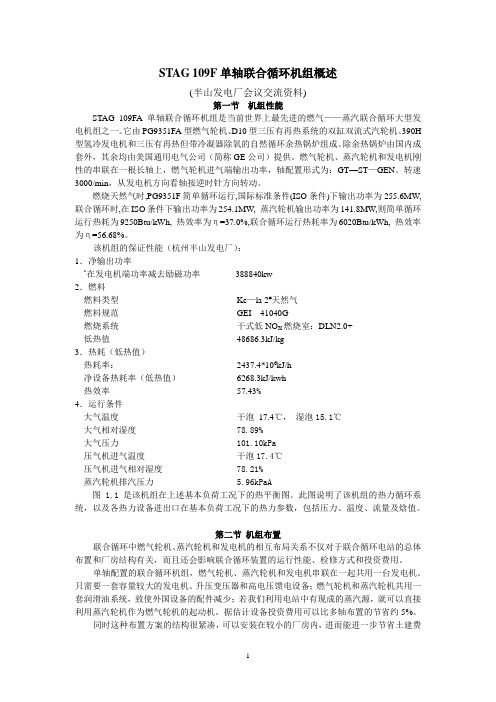
STAG 109F单轴联合循环机组概述(半山发电厂会议交流资料)第一节机组性能STAG 109FA单轴联合循环机组是当前世界上最先进的燃气——蒸汽联合循环大型发电机组之一。
它由PG9351FA型燃气轮机、D10型三压有再热系统的双缸双流式汽轮机、390H 型氢冷发电机和三压有再热但带冷凝器除氧的自然循环余热锅炉组成。
除余热锅炉由国内成套外,其余均由美国通用电气公司(简称GE公司)提供。
燃气轮机、蒸汽轮机和发电机刚性的串联在一根长轴上,燃气轮机进气端输出功率,轴配置形式为:GT—ST—GEN。
转速3000/min,从发电机方向看轴按逆时针方向转动。
燃烧天然气时,PG9351F简单循环运行,国际标准条件(ISO条件)下输出功率为255.6MW,联合循环时,在ISO条件下输出功率为254.1MW, 蒸汽轮机输出功率为141.8MW,则简单循环运行热耗为9250Btu/kWh, 热效率为η=37.0%,联合循环运行热耗率为6020Btu/kWh, 热效率为η=56.68%。
该机组的保证性能(杭州半山发电厂):1.净输出功率*在发电机端功率减去励磁功率388840kw2.燃料燃料类型Ke—la 2#天然气燃料规范GEI 41040G燃烧系统干式低NO X燃烧室:DLN2.0+低热值48686.3kJ/kg3.热耗(低热值)热耗率:2437.4*106kJ/h净设备热耗率(低热值)6268.3kJ/kwh热效率57.43%4.运行条件大气温度干泡17.4℃,湿泡15.1℃大气相对湿度 78.89%大气压力 101.10kPa压气机进气温度干泡17.4℃压气机进气相对湿度 78.21%蒸汽轮机排汽压力 5.96kPaA图 1.1是该机组在上述基本负荷工况下的热平衡图。
此图说明了该机组的热力循环系统,以及各热力设备进出口在基本负荷工况下的热力参数,包括压力、温度、流量及焓值。
第二节机组布置联合循环中燃气轮机、蒸汽轮机和发电机的相互布局关系不仅对于联合循环电站的总体布置和厂房结构有关,而且还会影响联合循环装置的运行性能、检修方式和投资费用。
美国海军潜艇序列表大全

Herring Kingfish Shad Silversides Trigger Wahoo Whale Angler Bashaw Bluegill Bream Cavalla Cobia Croaker Dace Dorado Flasher Flier Flounder Gabilan Gunnel Gurnard Haddo Hake Harder Hoe Jack Lapon Mingo Muskallunge Paddle Pargo Peto PoSS-127 SS-128 SS-129 SS-130 SS-131 SS-132 SS-133 SS-134 SS-135 SS-136 SS-137 SS-138 SS-139 SS-140 SS-141 SS-142 SS-143 SS-144 SS-145 SS-146 SS-147 SS-148 SS-149 SS-150 SS-151 SS-152 SS-153 SS-154 SS-155 SS-156 SS-157 SS-158 SS-159 SS-160
Seawolf Tambor Tautog Thresher Triton Trout Tuna Mackerel Marlin Gar Grampus Grayback Grayling Grenadier Gudgeon Gato Greenling Grouper Growler Grunion Guardfish Albacore Amberjack Barb Blackfish Bluefish Bonefish Cod Cero Corvina Darter Drum Flying Fish Finback Haddock Halibut
SS-233 SS-234 SS-235 SS-236 SS-237 SS-238 SS-239 SS-240 SS-241 SS-242 SS-243 SS-244 SS-245 SS-246 SS-247 SS-248 SS-249 SS-250 SS-251 SS-252 SS-253 SS-254 SS-255 SS-256 SS-257 SS-258 SS-259 SS-260 SS-261 SS-262 SS-263 SS-264 SS-265 SS-266 SS-267 SS-268
SN74HC148NSR中文资料
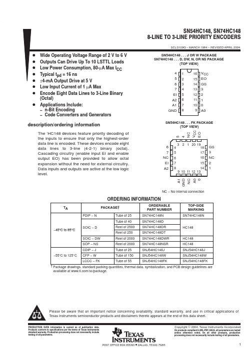
PACKAGING INFORMATIONOrderable Device Status (1)Package Type Package DrawingPins Package Qty Eco Plan (2)Lead/Ball Finish MSL Peak Temp (3)SN54HC148J ACTIVE CDIP J 161TBD A42SNPB N /A for Pkg Type SN74HC148D ACTIVE SOIC D 1640Green (RoHS &no Sb/Br)CU NIPDAU Level-1-260C-UNLIM SN74HC148DE4ACTIVE SOIC D 1640Green (RoHS &no Sb/Br)CU NIPDAU Level-1-260C-UNLIM SN74HC148DR ACTIVE SOIC D 162500Green (RoHS &no Sb/Br)CU NIPDAU Level-1-260C-UNLIM SN74HC148DRE4ACTIVE SOIC D 162500Green (RoHS &no Sb/Br)CU NIPDAU Level-1-260C-UNLIM SN74HC148DT ACTIVE SOIC D 16250Green (RoHS &no Sb/Br)CU NIPDAU Level-1-260C-UNLIM SN74HC148DTE4ACTIVE SOIC D 16250Green (RoHS &no Sb/Br)CU NIPDAU Level-1-260C-UNLIM SN74HC148DW OBSOLETE SOIC DW 16TBDCall TI Call TISN74HC148DWR ACTIVE SOIC DW 162000Green (RoHS &no Sb/Br)CU NIPDAU Level-1-260C-UNLIM SN74HC148DWRE4ACTIVE SOIC DW 162000Green (RoHS &no Sb/Br)CU NIPDAU Level-1-260C-UNLIM SN74HC148N ACTIVE PDIP N 1625Pb-Free (RoHS)CU NIPDAU N /A for Pkg Type SN74HC148NE4ACTIVE PDIPN 1625Pb-Free (RoHS)CU NIPDAU N /A for Pkg Type SN74HC148NSR ACTIVE SO NS 162000Green (RoHS &no Sb/Br)CU NIPDAU Level-1-260C-UNLIM SN74HC148NSRE4ACTIVE SO NS 162000Green (RoHS &no Sb/Br)CU NIPDAULevel-1-260C-UNLIMSNJ54HC148FK ACTIVE LCCC FK 201TBD POST-PLATE N /A for Pkg Type SNJ54HC148J ACTIVE CDIP J 161TBD A42SNPB N /A for Pkg Type SNJ54HC148WACTIVECFPW161TBDA42N /A for Pkg Type(1)The marketing status values are defined as follows:ACTIVE:Product device recommended for new designs.LIFEBUY:TI has announced that the device will be discontinued,and a lifetime-buy period is in effect.NRND:Not recommended for new designs.Device is in production to support existing customers,but TI does not recommend using this part in a new design.PREVIEW:Device has been announced but is not in production.Samples may or may not be available.OBSOLETE:TI has discontinued the production of the device.(2)Eco Plan -The planned eco-friendly classification:Pb-Free (RoHS),Pb-Free (RoHS Exempt),or Green (RoHS &no Sb/Br)-please check /productcontent for the latest availability information and additional product content details.TBD:The Pb-Free/Green conversion plan has not been defined.Pb-Free (RoHS):TI's terms "Lead-Free"or "Pb-Free"mean semiconductor products that are compatible with the current RoHS requirements for all 6substances,including the requirement that lead not exceed 0.1%by weight in homogeneous materials.Where designed to be soldered at high temperatures,TI Pb-Free products are suitable for use in specified lead-free processes.Pb-Free (RoHS Exempt):This component has a RoHS exemption for either 1)lead-based flip-chip solder bumps used between the die and package,or 2)lead-based die adhesive used between the die and leadframe.The component is otherwise considered Pb-Free (RoHS compatible)as defined above.Green (RoHS &no Sb/Br):TI defines "Green"to mean Pb-Free (RoHS compatible),and free of Bromine (Br)and Antimony (Sb)based flame retardants (Br or Sb do not exceed 0.1%by weight in homogeneous material)(3)MSL,Peak Temp.--The Moisture Sensitivity Level rating according to the JEDEC industry standard classifications,and peak solder temperature.6-Dec-2006Important Information and Disclaimer:The information provided on this page represents TI's knowledge and belief as of the date that it is provided.TI bases its knowledge and belief on information provided by third parties,and makes no representation or warranty as to the accuracy of such information.Efforts are underway to better integrate information from third parties.TI has taken and continues to take reasonable steps to provide representative and accurate information but may not have conducted destructive testing or chemical analysis on incoming materials and chemicals.TI and TI suppliers consider certain information to be proprietary,and thus CAS numbers and other limited information may not be available for release.In no event shall TI's liability arising out of such information exceed the total purchase price of the TI part(s)at issue in this document sold by TI to Customer on an annualbasis.6-Dec-2006IMPORTANT NOTICETexas Instruments Incorporated and its subsidiaries (TI) reserve the right to make corrections, modifications, enhancements, improvements, and other changes to its products and services at any time and to discontinue any product or service without notice. Customers should obtain the latest relevant information before placing orders and should verify that such information is current and complete. All products are sold subject to TI’s terms and conditions of sale supplied at the time of order acknowledgment.TI warrants performance of its hardware products to the specifications applicable at the time of sale in accordance with TI’s standard warranty. T esting and other quality control techniques are used to the extent TI deems necessary to support this warranty. Except where mandated by government requirements, testing of all parameters of each product is not necessarily performed.TI assumes no liability for applications assistance or customer product design. Customers are responsible for their products and applications using TI components. T o minimize the risks associated with customer products and applications, customers should provide adequate design and operating safeguards.TI does not warrant or represent that any license, either express or implied, is granted under any TI patent right, copyright, mask work right, or other TI intellectual property right relating to any combination, machine, or process in which TI products or services are used. Information published by TI regarding third-party products or services does not constitute a license from TI to use such products or services or a warranty or endorsement thereof. Use of such information may require a license from a third party under the patents or other intellectual property of the third party, or a license from TI under the patents or other intellectual property of TI.Reproduction of information in TI data books or data sheets is permissible only if reproduction is without alteration and is accompanied by all associated warranties, conditions, limitations, and notices. Reproduction of this information with alteration is an unfair and deceptive business practice. TI is not responsible or liable for such altered documentation.Resale of TI products or services with statements different from or beyond the parameters stated by TI for that product or service voids all express and any implied warranties for the associated TI product or service and is an unfair and deceptive business practice. TI is not responsible or liable for any such statements. Following are URLs where you can obtain information on other Texas Instruments products and application solutions:Products ApplicationsAmplifiers Audio /audioData Converters Automotive /automotiveDSP Broadband /broadbandInterface Digital Control /digitalcontrolLogic Military /militaryPower Mgmt Optical Networking /opticalnetwork Microcontrollers Security /securityLow Power Wireless /lpw Telephony /telephonyVideo & Imaging /videoWireless /wirelessMailing Address:Texas InstrumentsPost Office Box 655303 Dallas, Texas 75265Copyright 2006, Texas Instruments Incorporated。
温湿度测量仪说明书AS109
地址 0x0000 0x0001 0x0002 0x0003 0x0004 0x0005 0x0006 0x0007
寄存器信息 设备型号
版本号(低 8 位) 设备 ID 高 16 位 设备 ID 低 16 位 温度上限报警值 温度上限报警使能 温度下限报警值 温度下限报警使能
地址 0x0008 0x0009 0x000A 0x000B 0x000C 0x000D 0x000E 0x000F
湿度: 01D7 = 1×256+13×16+4 = 471 => 湿度 = 471÷10=47.1%RH
温度: 00D6 = 13×16+6 = 214
=> 温度 = 214÷10 = 21.4℃
◎ CRC 码的计算方法
1.预置1个16位的寄存器为十六进制FFFF(即全为1);称此寄存器为CRC寄存器;
按键
功能 菜单选择键 功能/数值增加键 功能/数值减少键
说明
切换显示菜单, 在多级菜单中可返回上一级菜单或退出菜单功能 菜单界面中执行上移或 切换功能及参数调整界面中执行参数“加” 菜单界面中执行下移或 切换功能及参数调整界面中执行参数“减”
确认键
在菜单中执行确认功能或进入下一级子菜单。
报警指示灯
报警指示灯状态: 低亮报警开、灭报警关、高亮闪烁达到报警条件
图 2 固定贴纸
安装方式二 1、安装前先取出固定底座一套(如图 4、5 所示); 2、用 M2.5*5(附件有提供)的 3 个螺丝先把产吕固定底座固定 在产品的后盖上,如图 6 所示:
图 3 固定孔
图 4 产品固定底座
图 5 墙面固定底座
3、用 M4 的 3 个螺丝(附件有提供)先墙面固定底座固定在
FW109 火灾报警控制器(联动型) 安装使用说明书
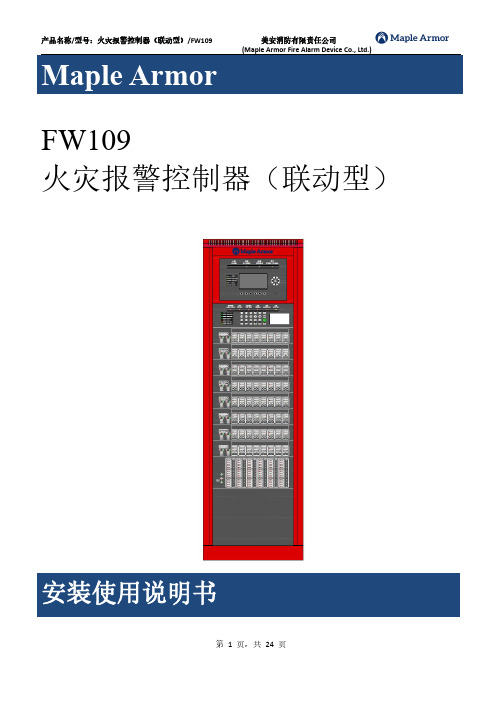
FW109火灾报警控制器(联动型)目录概述 (3)FW109火灾报警控制器(联动型) (3)特性 (4)规格参数及特性 (5)主要功能 (6)安装及调试 (7)系统设计要求 (7)电池连接方法 (7)现场调试 (7)操作界面说明 (11)界面说明 (11)控制器打印机的打印纸安装与使用 (20)常见故障分析及维护 (22)附录一操作级别划分表 (23)FW109火灾报警控制器(联动型)FW109型火灾报警控制器(联动型)是为中小型场所设计的智能火灾报警设备,支持99台控制器联网。
每台控制器支持16路回路(200点现场部件/回路)。
产品满足国标GB4717-2005图1控制器基本构成特性1.两总线无极性,采用地址编码技术。
整个系统只用两根总线,建筑物布线极其简单,布线路径及方式任意,且不分先后顺序,提高了布线可靠性,也便于穿线施工和线路维修,并可大大降低工程造价。
2.液晶中文界面,全部采用汉字显示。
各种操作以菜单形式给出提示,显示内容一目了然,操作起来便捷、清楚、直观,实现了良好的人机对话。
3.所接现场设备均内嵌微处理器。
点型光电感烟火灾探测器和点型感温火灾探测器均实时监视现场参数的变化,通过微处理器对采集到的现场参数进行分析、判断,从而大大降低探测器与控制器之间的信息传输量,进一步提高了火灾报警系统的可靠性。
4.黑匣子功能。
控制器内置大容量存储器,可以长时间保存控制器开机、关机、火警、各种故障、联动设备的启动及停止等信息。
便于事故发生后的信息查询。
5.极强的抗干扰能力。
控制器无论是硬件还是软件都有良好的抗干扰措施,控制器能在电磁干扰强的环境下正常稳定运行。
6.主从组网方式。
可以多台控制器组网,组网的控制器之间分集中机和区域机,一台控制器报警可以在报价机器和集中机上得到响应。
从而可以组成非常大的报警系统。
7.超大的系统容量。
单台控制器随种类不同,可以组成系统总报警回路从1回路到16回路,组网后系统容量更大。
汽车常用英文术语2

发动机后悬置托架 发动机安装支架 排气管安装支架,后 前翼子板支架,左 加油管固定支座 搁脚板支架 前扬声器支架(右) 油泵支架 燃油箱安装支架,前 保险丝盒支架 防盗喇叭支架 管夹支架 仪表板骨架支架,右 千斤顶支架 地图灯支架 动力转向管支架 把手支架 音响支架,左 贮液罐支架总成 谐振器支架 后保险杠侧支架,A 后保险杠固定支架 后排座椅靠背支架 后挂钩支架,右 保险杠侧支架 后保险杠侧支架 后稳定杆支架(右) 传感器支架 方向柱支架,外 行李箱装饰板支架,A 前连接杆衬套 橡胶套 稳定杆衬套 蜂鸣器 电缆 油门拉索总成 自动变速箱拉索 机仓盖拉索 行李箱盖拉索总成 后制动钳总成,左 倒車摄像头总成 碳罐 轮辋装饰罩 加油口盖总成
顶盖中弓形梁 行李箱盖工具盒 前限位器支座 前柱下铰链支座总成 顶罩侧板,右 轴承总成 支架 风机支架 离合器踏板支架总成 排气管支架 前保险杠支架,左 前座椅安装支架,左 加热器支架总成,A 千斤顶支架总成 消音器安装支架 焊接前地板手刹车支架 后挂钩支架总成 备胎支架 油门线支架 支架 拉手支架 电瓶支架总成 制动阀支架总成 碳罐支架 仪表板支架 干燥瓶支架 动力转向油罐支架总成 散热器支架(右) 座椅支架,右 传感器安装支架总成 稳定杆夹箍 支架 支架总成 制动管支架(右) 拉索支架 驻车钢索支架 支架—线夹 离合器管支架 压缩机支架 四通支架 杂物盒支架,前 电脑板支架 发动机装饰盖支架 发动机安装支架
85 86 87 88 89 90 91 92 93 94 95 96 97 98 99 100 101 102 103 104 105 106 107
总装 总装 总装 焊装 焊装 焊装 总装 总装 总装 总装 总装 总装 总装 焊装 总装 总装 总装 总装 总装 总装 焊装 焊装 焊装
长线驱动器——精选推荐

长线驱动器目 录安全操作指南' (1)1、RGB109简介 (2)1.1 概述 (2)1.2 规格特征 (2)主要功能及特征 (2)主要规格 (2)2、RGB109的使用 (3)2.1 设备的连接 (3)2.2 设备的结构 (4)后面板说明 (4)LCD液晶显示屏及按键说明 (6)2.3 设备的操作 (6)3、RGB109包装说明 (7)4、RGB-105长线驱动器 (7)4.1 技术性能及指标 (7)4.2 主要功能及设置 (7)5、常见故障及维修 (7)安全操作指南为确保设备可靠使用以及人员的安全,在安装、使用和维护时,请遵守以下事项:1:系统接地:系统必须要有完善的接地。
否则,不仅会造成信号的干扰和不稳定,而且还有可能因漏电引起人身事故。
2:禁止改变原设计:禁止对本产品的机械和电器设计更改或增添任何部件。
否则,生产厂家对由此所带来的危害性结果不负有任何责任3:从设备上插、拔信号线时,设备一定要断电操作,防止击穿芯片损坏设备。
带电热插、拔对设备造成的损坏不在保修范围。
4:请勿使用两芯插头,确保设备的输入电源为220V 50Hz的交流电。
5:机器内有交流220V高压部件,请勿擅自打开机壳,以免发生触电危险。
6:不要将系统设备置于过冷或者过热的地方。
7:设备电源在工作时会发热,因此要保持工作环境的良好通风,以免温度过高而损坏机器。
8:阴雨潮湿天气或长时间不使用时,应关闭设备电源总闸。
9:非专业人士未经许可,请不要试图拆开设备机箱,不要私自维修,以免发生意外事故加重设备的损坏程度。
10:不要将任何化学药品或液体洒在设备上或其附近。
1 RGB109简介1.1 概述在多媒体应用系统中,经常需要将模拟计算机显示信号进行远距离传输,这给工程中带来了许多问题,其中比较突出的问题有:1.由于传输线缆过长或信号不佳以及系统中其他设备的影响,图像会产生模糊、重影及拖尾等现象。
2.由于行场同步信号和三基色信号分离传输,当信号传至显示器一端时,会出现图像的偏移。
- 1、下载文档前请自行甄别文档内容的完整性,平台不提供额外的编辑、内容补充、找答案等附加服务。
- 2、"仅部分预览"的文档,不可在线预览部分如存在完整性等问题,可反馈申请退款(可完整预览的文档不适用该条件!)。
- 3、如文档侵犯您的权益,请联系客服反馈,我们会尽快为您处理(人工客服工作时间:9:00-18:30)。
Temperature Range -55oC to +135oC -55oC to +135oC -55oC to +135oC
ELECTRICAL CHARACTERISTICS (TA = 25oC unless otherwise specified)
SYMBOL IGSS VGS(off) BVGSS IDSS ID(off) rDS(on) Cdg(off) Csg(off) Cdg(on) + Csg(on) td(on) tr td(off) tf PARAMETER Gate Reverse Current (Note 1) Gate-Source Cutoff Voltage Gate-Source Breakdown Voltage Drain Saturation Current (Note 2) Drain Cutoff Current (Note 1) Drain-Source ON Resistance Drain-Gate OFF Capacitance Source-Gate OFF Capacitance Drain-Gate Plus Source-Gate ON Capacitance Turn On Delay Time Rise Time Turn OFF Delay Time Fall Time
• • • • • •
APPLICATIONS Analog Switches Choppers Commutators Low-Noise Audio Amplifiers
• • • •
PIN CONFIGURATION
SOT-23 G
TO-92
ABSOLUTE MAXIMUM RATINGS (TA = 25oC unless otherwise specified) Gate-Drain or Gate-Source Voltage . . . . . . . . . . . . . . . . -25V Gate Current . . . . . . . . . . . . . . . . . . . . . . . . . . . . . . . . . 50mA Storage Temperature Range . . . . . . . . . . . . . -55oC to +150oC Operating Temperature Range . . . . . . . . . . . -55oC to +135oC Lead Temperature (Soldering, 10sec) . . . . . . . . . . . . . +300oC Power Dissipation . . . . . . . . . . . . . . . . . . . . . . . . . . . . 360mW Derate above 25oC . . . . . . . . . . . . . . . . . . . . . . . 3.3mW/ oC
ns
NOTES: 1. Approximately doubles for every 10 C increase in TA. 2. Pulse test duration = 300µs; duty cycle ≤3%. 3. For design reference only, not 100% tested.
元器件交易网N-ຫໍສະໝຸດ hannel JFET Switch
CORPORATION
J108 – J110 / SST108 – SST110
FEATURES Low Cost Automated Insertion Package Low Insertion Loss No Offset or Error Voltages Generated by Closed Switch Purely Resistive High Isolation Resistance from Driver Fast Switching Low Noise
NOTE: Stresses above those listed under "Absolute Maximum Ratings" may cause permanent damage to the device. These are stress ratings only and functional operation of the device at these or any other conditions above those indicated in the operational sections of the specifications is not implied. Exposure to absolute maximum rating conditions for extended periods may affect device reliability.
TEST CONDITIONS VDS = 0V, VGS = -15V VDS = 5V, ID = 1µA VDS = 0V, IG = -1µA VDS = 15V, VGS = 0V VDS = 5V, VGS = -10V VDS ≤0.1V, VGS = 0V VDS = 0, VGS = -10V (Note 3) f = 1MHz VDS = VGS = 0 (Note 3) Switching Time Test Conditions (Note 3) J107 J109 J110 VDD 1.5V 1.5V 1.5V VGS(off) -12V -7V -5V RL 150Ω 150Ω 150Ω
D S
G D S
5018
PRODUCT MARKING (SOT-23) SST108 I08 SST109 I09 SST110 I10
ORDERING INFORMATION Part Package J108-110 Plastic TO-92 XJ108-110 Sorted Chips in Carriers SST109-110 Plastic SOT-23
o
108 109 110 UNITS MIN TYP MAX MIN TYP MAX MIN TYP MAX -3 -3 -3 nA -3 -10 -2 -6 -0.5 -4 V -25 -25 -25 80 40 10 mA 3 3 3 nA 8 12 18 Ω 15 15 15 15 85 4 1 6 30 4 1 6 30 15 85 4 1 6 30 15 85 pF
