1N4448W开关二极管
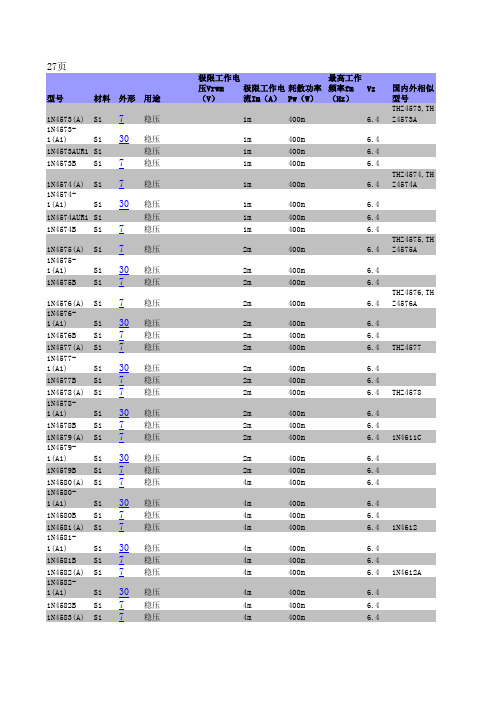
1N系列二极管

250μ 250μ 250μ
250μ 250μ
250μ 250μ 250μ
250μ 250μ
250μ 250μ 250μ
250μ 250μ
250μ 250μ 250μ
250μ
400m
6.4
2m
400m
6.4
4m
400m
6.4
4m
400m
4m
400m
4m
400m
6.4 6.4 6.4 1N4612
4m
400m
4m
400m
4m
400m
6.4 6.4 6.4 1N4612A
4m
400m
6.4
4m
400m
6.4
4m
400m
6.4
1N4583-
1(A1)
Si 30 稳压
1N4583B Si 7 稳压
)
Si 7
稳压 稳压
1N4616DUR1 Si
1N4617(-1) Si 7
1N4617C(C1
)
Si 7
稳压 稳压
稳压
1N4617CUR1 Si
1N4617D(D1
)
Si 7
稳压 稳压
1N4617DUR1 Si
1N4618(-1) Si 7
1N4618C(C1
)
Si 7
稳压 稳压
稳压
4m 4m 4m
3.6 3.6
3.6 3.6 3.9 MZ4622
3.9 3.9
3.9 3.9 4.3 MZ4623
常用开关二极管型号及主要参数

常用开关二极管型号及主要参数开关二极管是一种具有特殊结构的二极管,其主要作用是实现电路开关控制功能。
在数字电子、通信、电源管理等领域都广泛应用。
以下将对常用的几种开关二极管型号及其主要参数进行介绍。
1.1N4148开关二极管-最大反向电压:100V-最大正向电流:200mA-最大功耗:500mW- 开关时间:4ns1N4148是一种常见的开关二极管,具有快速开关、低反向电流、高正向导通能力等特点。
广泛应用于数字逻辑门、开关电路以及高频信号放大电路中。
2.1N4007开关二极管-最大反向电压:1000V-最大正向电流:1A-最大功耗:3W-开关时间:<50μs1N4007是一种经典的开关二极管,主要用于低频交流电源整流和保护电路,具有高耐压、大电流特点,适用于一般电源电路。
3.1N5822开关二极管-最大反向电压:40V-最大正向电流:3A-最大功耗:2.5W- 开关时间:20ns1N5822是一种快恢复型开关二极管,具有快速恢复时间和低导通损耗的特点。
常用于开关电源和充电电路中,以提高电路的稳定性和效率。
4.2N3904开关二极管-最大反向电压:40V-最大正向电流:200mA-最大功耗:625mW- 开关时间:20ns2N3904是一种常见的NPN型开关二极管,适用于低功耗开关电路和放大电路。
具有高动态特性、低饱和电压和低输入电容等特点。
5.PN2222开关二极管-最大反向电压:40V-最大正向电流:600mA-最大功耗:500mW- 开关时间:25nsPN2222是一种广泛应用的PNP型开关二极管,常用于电源管理、接口驱动、瞬态抑制等电路。
具有较高的集电极电流和较低的饱和电压。
以上是几种常见的开关二极管型号及其主要参数。
在实际应用中,选择合适的开关二极管要综合考虑最大反向电压、最大正向电流、功耗和开关时间等参数,并根据具体应用需求进行合适选择。
1N4148 4448--小信号肖特基二极管

mW
典型热阻 Type Thermal Resistance
RθJA
300
K/W
工作结温和存储温度
Operating junction and storage temperature range
Tj, TSTG
-50 --- +150
℃
电特性 TA = 25℃ 除非另有规定。
Electrical Characteristics Ratings at 25℃ ambient temperature unless otherwise specified.
trr
---
4.0
nS
IF = 10mA — IR = 1.0mA
VR = 6.0V, RL =100Ω
- 347 -
大昌电子 DACHANG ELECTRONICS
正向电流 IF(A) IF Instantaneous Forward Current (A)
SIYU R
特性曲线 Characteristic Curves
符号
最小值 最大值
单位
Symbols
MIN.
MAX.
Unit
测试条件 Test Condition
正向电压
Forward voltage
反向电流
Reverse current
1N4148
1N4448
VFM
1N4448
IRM
---
1.0
0.62
0.72
---
1.0
5.0
---
50
30
25
IF =10mA
符号
Symbols VRM
VRRM
1N4148,1N4448中文资料

封装: DO-35 玻璃封装 Case: DO-35 Glass Case
Unit:mm
极性: 色环端为负极 Polarity: Color band denotes cathode end 安装位置: 任意 Mounting Position: Any
极限值和温度特性 TA = 25℃ 除非另有规定。 Maximum Ratings & Thermal Characteristics Ratings at 25℃ ambient temperature unless otherwise specified.
不重复峰值反向电压 Non-repetitive Peak Reverse Voltage
反向峰值电压 peak repetitive Reverse Voltage 最大正向平均电流 Forward Continuous Current 平均整流输出电流 Average Rectified Output Current
1N4148 / 1N4448
DO-35 Glass
max. 0.52
小信号肖特基二极管 Small Signal Schottky Diodes
特征 Features
1.8 0.2
CATHODE MARK
min. 27.5 3.8 0.2 min. 27.5
·反向漏电流小。Low reverse leakage ·开关速度快。Fast switching speed ·最大功率耗散500mW。Maximum power dissipation 500mW ·高稳定性和可靠性。High stability and high reliability
符号
1N4148、1N4150、1N4448 开关二极管

“电子爱好者”网站是一个面向广大电子爱好者、大专院校学生、中小型企业工程技 术人员的电子技术应用、推广专业网站。主要内容有:电子技术应用交流,器件资料、电 子设计软件下载,电子技术支持服务,电子产品发布、转让和引进等信息。
本资料由"电子爱好者"网站收集整理,版权属原作者
The products listed in this document are designed to be used with ordinary electronic equipment or devices (such as audio visual equipment, office-automation equipment, communications devices, electrical appliances and electronic toys). Should you intend to use these products with equipment or devices which require an extremely high level of reliability and the malfunction of with would directly endanger human life (such as medical instruments, transportation equipment, aerospace machinery, nuclear-reactor controllers, fuel controllers and other safety devices), please be sure to consult with our sales representative in advance.
德昌电子1N4448W开关二极管sot-123规格书

Number: DB-022TAK CHEONG®SEMICONDUCTORGreen Product400mW SOD-123 SURFACE MOUNTSmall Outline Flat Lead Plastic Package General Purpose Application Fast Switching DiodeAbsolute Maximum RatingsT A = 25°C unless otherwise notedSymbol Parameter Value UnitsP D Power Dissipation400 mW T STG Storage Temperature Range -65 to +150°C T J Operating Junction Temperature +150 °C V RSM Non-Repetitive Peak Reverse Voltage 100 V V RRM Repetitive Peak Reverse Voltage 75 V I FRM Repetitive Peak Forward Current 300 mA I OContinuous Forward Current 150mAI FSM Peak Forward Surge Current (Pulse Width=1us)2 AThese ratings are limiting values above which the serviceability of the diode may be impaired.Specification Features:Fast Switching Device (T RR <4.0 nS) General Purpose DiodesFlat Lead SOD-123 Small Outline Plastic Package Surface Device Type Mounting RoHS Compliant Green EMCMatte Tin(Sn) Lead FinishBand Indicates CathodeDEVICE MARKING CODE:Device Type Device Marking1N4148WD1 1N4448W D2 1N914BWD3Electrical CharacteristicsT A = 25°C unless otherwise notedLimitsSymbol Parameter Test Condition Min Max UnitB VBreakdown VoltageI R =100µA I R =5µA100 75VoltsI RReverse Leakage CurrentV R =20V V R =75V25 5nAµAV FForward Voltage 1N4448W, 1N914BW1N4148W1N4448W, 1N914BWI F =5mA I F =10mA I F =100mA 0.62 0.721.0 1.0Volts T RRReverse Recovery TimeI F =10mA I R =60mA R L =100Ω I RR =1mA4 nSCCapacitance V R =0V, f=1M HZ 4 pF1N 4148W /1N 4448W /1N 914B WSOD-123 Flat LeadNumber: DB-022TAK CHEONGSEMICONDUCTORTypical Performance CharacteristicsTotal CapacitanceForward Voltage vs Ambient TemperatureNumber: DB-022TAK CHEONGSEMICONDUCTORPower Derating CurveReverse Current vs Reverse VoltageNumber: DB-022TAK CHEONGSEMICONDUCTORFlat Lead SOD-123 Package OutlineNote: Dimensions are exclusive of Burrs, Mold Flash & Tie Bar extrusions.Number: DB-100 April 14, 2008 / A DISCLAIMER NOTICETAK CHEONGNOTICEThe information presented in this document is for reference only. Tak Cheong reserves the right to make changes without notice for the specification of the products displayed herein.The product listed herein is designed to be used with ordinary electronic equipment or devices, and not designed to be used with equipment or devices which require high level of reliability and the malfunction of with would directly endanger human life (such as medical instruments, transportation equipment, aerospace machinery, nuclear-reactor controllers, fuel controllers and other safety devices), Tak Cheong Semiconductor Co., Ltd., or anyone on its behalf, assumes no responsibility or liability for any damagers resulting from such improper use of sale.This publication supersedes & replaces all information reviously supplied. For additional information, please visit our website , or consult your nearest Tak Cheong’s sales office for further assistance.。
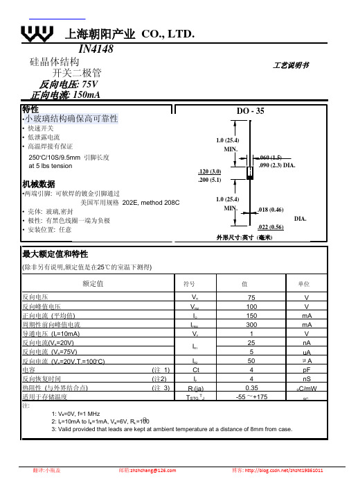
IN4148中文资料

DO - 35
1.0 (25.4) MIN.
.120 (3.0) .200 (5.1)
.060 (1.5) .090 (2.3) DIA.
1.0 (25.4) MIN.
.018 (0.46)
.022 (0.56) 外形尺寸:英寸 (毫米)
上海朝阳产业 CO., LTD.
IN4148
硅晶体结构 开关二极管
反向电压: 75V 正向电流: 150mA
工艺说明书
特性 •小玻璃结构确保高可靠性
• 快速开关 • 低泄露电流 • 高温焊接有保证
250oC/10S/9.5mm 引脚长度 at 5 lbs tension
机械数据
•两端引脚: 可软焊的镀金引脚通过 美国军用规格 202E, method 208C
翻译:小瓶盖
邮箱:zhzhchang@
博客: /zhzht19861011
nA
5
uA
反向电流 (VR=20V,TJ=100oC)
IR2
50
A
电容
(注 1)
Ct
4
pF
反向恢复时间
(注2)
IF
4
nS
热阻性 (与外界结合点) 适用于存储温度
注:
(注 3)
R(ja) TSTG,TJ
0.35 -55 +175
oC/mW
oC
1: VR=0V, f=1 MHz 2: IF=10mA to IR=1mA, VR=6V, RL=100 3: Valid provided that leads are kept at ambient temperature at a distance of 8mm from case.
IN4148WS贴片开关二极管

FIG. 1- FORWARD CHARACTERISTICS
1000 10,000
FIG. 2-LEAKAGE CURRENT VS JUNCTION TEMPERATURE
100
IR, LEAKAGE CURRENT(nA)
0 1 2
1000
10
100
1.0
10
0ห้องสมุดไป่ตู้1
0.01
1 0 100 200
VRRM VRWM VR VR(RMS) IFM IO IFSM Pd RΘJA
Tj
TSTG VRM
SYMBOLS
Reverse current Capacitance between terminals Reverse recovery time
VF1 VF2 VF3 VF4 IR1 IR2 CT trr
Dimensions in millimeters and (inches)
MAXIMUM RATINGS AND ELECTRICAL CHARACTERISTICS
Maximum ratings and electrical characteristics, Single diode @TA=25C PARAMETER Peak repetitive peak reverse voltage Working peak reverse voltage DC Blocking voltage RMS Reverse voltage Forward continuous current Average rectified output current Peak forward current @=1.0*s @=1.0s Power dissipation Thermal resistance junction to ambient Junction temperature Storage temperature Non-Repetitive peak reverse voltage Electrical ratings @TA=25C PARAMETER Froward voltage
Diodes二极管1N4448W-7-F选型手册

FAST SWITCHING SURFACE MOUNT DIODEFeatures• Fast Switching Speed • Surface Mount Package Ideally Suited for Automated Insertion • For General Purpose Switching Applications • High Conductance • Totally Lead-Free & Fully RoHS Compliant (Notes 1 & 2) • Halogen and Antimony Free. “Green” Device (Note 3) • Qualified to AEC-Q101 Standards for High ReliabilityMechanical Data• Case: SOD123• Case Material: Molded Plastic. UL Flammability ClassificationRating 94V-0 • Moisture Sensitivity: Level 1 per J-STD-020 • Terminals: Matte Tin Finish annealed over Alloy 42 leadframe(Lead Free Plating). Solderable per MIL-STD-202, Method 208 • Polarity: Cathode Band • Weight: 0.01 grams (approximate)Ordering Information (Note 4)Part NumberCompliance Case Packaging1N4448W-7-F Standard SOD123 3000/Tape & Reel 1N4448WQ-7-FAutomotive SOD123 3000/Tape & ReelNotes: 1. No purposely added lead. Fully EU Directive 2002/95/EC (RoHS) & 2011/65/EU (RoHS 2) compliant.2. See /quality/lead_free.html for more information about Diodes Incorporated’s definitions of Halogen- and Antimony-free, "Green" and Lead-free.3. Halogen- and Antimony-free "Green” products are defined as those which contain <900ppm bromine, <900ppm chlorine (<1500ppm total Br + Cl) and<1000ppm antimony compounds.4. For packaging details, go to our website at /products/packages.htmlMarking InformationDate Code KeyYear 1998 1999 2000 …20072008200920102011201220132014 2015 2016201720182019CodeJ K L … U VWX Y ZA B C D E F GMonth Jan Feb Mar Apr May Jun Jul Aug Sep Oct Nov DecCode 1 2 3 4 5 6 7 8 9 O N DTop ViewSOD123T5 = Product Type Marking Code YM = Date Code Marking Y = Year (ex: B = 2014)M = Month (ex: 9 = September)T5Y MMaximum Ratings (@T A = +25°C, unless otherwise specified.)Characteristic Symbol Value UnitNon-Repetitive Peak Reverse Voltage V RM100 V Peak Repetitive Reverse VoltageWorking Peak Reverse Voltage DC Blocking Voltage V RRM V RWM V R 75 V RMS Reverse Voltage V R(RMS)53 V Forward Continuous Current I FM500 mA Average Rectified Output Current I O250 mA Non-Repetitive Peak Forward Surge Current @t = 1.0μs@t = 1.0s I FSM4.0 1.0AThermal CharacteristicsCharacteristic Symbol Value UnitPower Dissipation (Note 5) P D 400 mW Thermal Resistance Junction to Ambient Air (Note 5) R θJA315 °C/W Operating and Storage Temperature Range T J , T STG-65 to +150 °CElectrical Characteristics (@T A = +25°C, unless otherwise specified.)Characteristic Symbol Min Max Unit Test ConditionReverse Breakdown Voltage (Note 6) V (BR)R 75 ⎯ V I R = 10μAForward Voltage V FM0.62 ⎯ ⎯ ⎯ 0.720.8551.0 1.25 V I F = 5.0mA I F = 10mA I F = 100mA I F = 150mAPeak Reverse Current (Note 6) I RM ⎯2.5 50 30 25 μAμAμA nA V R = 75V V R = 75V, T J = +150°C V R = 25V, T J = +150°C V R = 20VTotal Capacitance C T ⎯ 4.0 pF V R = 0, f = 1.0MHzReverse Recovery Time t rr ⎯4.0 ns I F = I R = 10mA,I rr = 0.1 x I R , R L = 100ΩNotes:5. Part mounted on FR-4 PC board with 1 inch by 1 inch pad layout.6. Short duration pulse test used to minimize self-heating effect.P , P O W E R D I S S I P A T I O N (m W )D T , AMBIENT TEMPERATURE (C)Fig. 1 Power Derating CurveA °02004005001003001101001000Figure 2 Typical Forward Characteristics V , INSTANTANEOUS FORWARD VOLTAGE (mV)F I , I N S T A N T A N E O U S F O R W A R D C U R R E N T (m A )FPackage Outline DimensionsPlease see AP02002 at /datasheets/ap02002.pdf for latest version.V , INSTANTANEOUS REVERSE VOLTAGE (V)Fig. 3 Typical Reverse Characteristics R I , I N S T A N T A N E O U S R E V E R S E C U R R E N T (µA )R V , DC REVERSE VOLTAGE (V)Fig. 4 Total Capacitance vs. Reverse Voltage R C , T O T A L C A P A C I T A N C E (p F )TI , FORWARD CURRENT (mA)Fig. 5 Reverse Recovery Time vs. Forward CurrentF t , R E V E R S E R E C O V E R Y T I M E (n S )r r 00.51.01.52.02.5SOD123Dim Min Max A 0.55 Typ B 1.40 1.70 C 3.55 3.85 H 2.55 2.85 J 0.00 0.10 K 1.00 1.35 L0.25 0.40 M 0.10 0.15α0 8°All Dimensions in mmSuggested Pad LayoutPlease see AP02001 at /datasheets/ap02001.pdf for the latest version.IMPORTANT NOTICEDIODES INCORPORATED MAKES NO WARRANTY OF ANY KIND, EXPRESS OR IMPLIED, WITH REGARDS TO THIS DOCUMENT, INCLUDING, BUT NOT LIMITED TO, THE IMPLIED WARRANTIES OF MERCHANTABILITY AND FITNESS FOR A PARTICULAR PURPOSE (AND THEIR EQUIVALENTS UNDER THE LAWS OF ANY JURISDICTION).Diodes Incorporated and its subsidiaries reserve the right to make modifications, enhancements, improvements, corrections or other changes without further notice to this document and any product described herein. Diodes Incorporated does not assume any liability arising out of the application or use of this document or any product described herein; neither does Diodes Incorporated convey any license under its patent or trademark rights, nor the rights of others. Any Customer or user of this document or products described herein in such applications shall assume all risks of such use and will agree to hold Diodes Incorporated and all the companies whose products are represented on Diodes Incorporated website, harmless against all damages.Diodes Incorporated does not warrant or accept any liability whatsoever in respect of any products purchased through unauthorized sales channel. Should Customers purchase or use Diodes Incorporated products for any unintended or unauthorized application, Customers shall indemnify and hold Diodes Incorporated and its representatives harmless against all claims, damages, expenses, and attorney fees arising out of, directly or indirectly, any claim of personal injury or death associated with such unintended or unauthorized application.Products described herein may be covered by one or more United States, international or foreign patents pending. Product names and markings noted herein may also be covered by one or more United States, international or foreign trademarks.This document is written in English but may be translated into multiple languages for reference. Only the English version of this document is the final and determinative format released by Diodes Incorporated.LIFE SUPPORTDiodes Incorporated products are specifically not authorized for use as critical components in life support devices or systems without the express written approval of the Chief Executive Officer of Diodes Incorporated. As used herein:A. Life support devices or systems are devices or systems which: 1. are intended to implant into the body, or2. support or sustain life and whose failure to perform when properly used in accordance with instructions for use provided in thelabeling can be reasonably expected to result in significant injury to the user.B. A critical component is any component in a life support device or system whose failure to perform can be reasonably expected to cause the failure of the life support device or to affect its safety or effectiveness.Customers represent that they have all necessary expertise in the safety and regulatory ramifications of their life support devices or systems, and acknowledge and agree that they are solely responsible for all legal, regulatory and safety-related requirements concerning their products and any use of Diodes Incorporated products in such safety-critical, life support devices or systems, notwithstanding any devices- or systems-related information or support that may be provided by Diodes Incorporated. Further, Customers must fully indemnify Diodes Incorporated and its representatives against any damages arising out of the use of Diodes Incorporated products in such safety-critical, life support devices or systems.Copyright © 2014, Diodes IncorporatedDimensions Value (in mm)G 2.250 X 0.900 X1 4.050 Y 0.950YXX1G。
1N4148快速开关二极管

Features:•High speed silicon switching diodes, axial leaded.•General purpose, industrial, military and space applications.•Hermetically sealed glass with a stud on either side of the glass passivated chip provides excellent stability.•Extremely low leakage and very high reliability.DO-35 Glass Axial PackageAbsolute Maximum Ratings (T A = 25°C unless otherwise specified)NOTE1. Cathode is marked by Band.Electrical Characteristics (T a = 25°C unless otherwise specified)DO-35, 52mm Taping Specification52mm Taping Specification1. T and A indicates axial tape and ammo packing (52mm tape spacing).2. 300mm (minimum) leader tape on every spool.3. Number of empty places allowed 0.25% without consecutive empty places.4. Ends of leads shall preferably not protrude beyond the tapes.5. Components shall be held sufficiently in the tape or tapes so that they can not come free in normal handling.Dimensions : Millimetres SpecificationsNotes:FRANCE –Farnell InOneTel No:++ 33 474 68 99 99Fax No:++33 474 68 99 90–Farnell InOne++ 45 44 53 66 66No:++ 45 44 53 66 02AUSTRIA –Farnell InOneTel No:++ 43 662 2180 680Fax No:++43 662 2180 670GERMANY –Farnell InOneTel No:++ 49 89 61 39 39 39Fax No:++49 89 613 59 01PORTUGAL –Farnell InOneTel No:++ 34 93 475 8804Fax No:++34 93 474 5288ESTONIA –Farnell InOneTel No:++ 358 9 560 7780Fax No:++358 9 345 5411NETHERLANDS –Farnell InOneTel No:++ 31 30 241 7373Fax No:++31 30 241 7333–Farnell InOne++ 44 8701 200 200No:++44 8701 200 201–++ 65 6788 0200No:++65 6788 0300HONG KONG –Farnell-Newark InOneTel No:++ 852 2268 9888Fax No:++852 2268 9899BELGIUM –Farnell InOneTel No:++ 32 3 475 2810Fax No:++32 3 227 3648BRAZIL – Farnell-Newark InOneTel No:++ 55 11 4066 9400Fax No:++55 11 4066 9410IRELAND –Farnell InOneTel No:++ 353 1 830 9277Fax No:++353 1 830 9016SPAIN –Farnell InOneTel No:++ 34 93 475 8805Fax No:++34 93 474 5107CHINA –Farnell-Newark InOneTel No:++86 10 6238 5152Fax No: ++86 10 6238 5022ITAL Y –Farnell InOneTel No:++ 39 02 93 995 200Fax No:++ 39 02 93 995 300SWEDEN –Farnell InOneTel No:++ 46 8 730 50 00Fax No:++46 8 83 52 62MALAYSIA –Farnell-Newark InOneTel No:++ 60 3 7873 8000Fax No:++60 3 7873 7000SWITZERLAND –Farnell InOneTel No:++ 41 1 204 64 64Fax No:++41 1 204 64 54DENMARK –Farnell InOneTel No:++ 45 44 53 66 44Fax No:++45 44 53 66 06–CPC–BuckHickman InOneNEW ZEALAND –Farnell InOneTel No:++ 64 9 357 0646Fax No:++64 9 357 0656 。
常用开关二极管型号及主要参数

常用开关二极管型号及主要参数开关二极管是电子元器件的一种,主要用于电路中的开关控制功能。
按照功能来说,开关二极管可以分为开关二极管和反向恢复二极管两种。
开关二极管通常用于低压电路中的开关控制电路,其主要参数有正向电压、反向电压、正向电流和反向电容等。
常用开关二极管型号1. 1N41481N4148是一种快速开关二极管,常用于高速开关电路和频繁开关电路的应用中。
其正向电压为100V,正向电流为300mA。
在开关频率高于1MHz时,其开关速度优于其他开关二极管。
2. 1N40071N4007是一种一般用途整流二极管,常用于低压电路中。
其正向电压为1000V,正向电流为1A。
由于其价格较低、结构简单,因此被广泛使用。
3. 1N58191N5819是一种快速恢复二极管,常用于功率电路中的开关控制电路。
其正向电压为40V,正向电流为1A。
由于其反向恢复时间短,可在高频开关电路中发挥较好的性能。
开关二极管的主要参数1. 正向电压正向电压是指正向工作时二极管的最大电压值,通常以Vf表示。
在超过正向电压时,二极管会开始导通。
2. 反向电压反向电压是指反向工作时二极管的最大电压值,通常以Vr表示。
在超过反向电压时,二极管会瞬时击穿并开始导通。
3. 正向电流正向电流是指正向工作时二极管的最大电流值,通常以If表示。
当二极管导通时,其正向电流会逐渐增大,并受到管子本身的导通能力和电路的限制。
4. 反向电容反向电容是指反向工作时二极管的电容值,通常以Cr表示。
反向电容主要由管子的内部结构以及与终端接触的材料等因素决定。
对于高频开关电路,反向电容应尽量小。
开关二极管是电子中不可或缺的元器件之一,其性能指标决定了电路的稳定性和可靠性。
以上介绍了三种常用的开关二极管型号及其主要参数,可根据实际需求进行选择和应用。
贴片开关二极管 1N4148W SOD-123 规格书推荐

Note 1:Device mounted on 1''x1'' FR4 PCB,1oz single-side copper.
1
D,Nov,2017
ELECTRICAL CHARACTERISTICS
Electrical Ratings @Ta=25℃
Parameter Symbol VF1 Forward voltage VF2 VF3 VF4 Reverse current Capacitance between terminals Reverse recovery time IR1 IR2 CT trr Min Typ Max 0.715 0.855 1.0 1.25 1 25 2 4 Unit V V V V μA nA pF ns Conditions IF=1mA IF=10mA IF=50mA IF=150mA VR=75V VR=20V VR=0V,f=1MHz IF=IR=10mA Irr=0.1XIR,RL=100Ω
Parameter Non-Repetitive Peak Reverse Voltage Peak Repetitive Peak Reverse Voltage Working Peak Reverse Voltage DC Blocking Voltage RMS Reverse Voltage Forward Continuous Current Average Rectified Output Current Non-Repetitive Peak Forward Surge Current @ t=8.3ms Power Dissipation 1N4148W BAV16W Thermal Resistance from Junction to Ambient(Note 1) Junction Temperature Storage Temperature Symbol VRM VRRM VRWM VR VR(RMS) IFM IO IFSM Pd RθJA Tj TSTG 71 300 150 2.0 350 400 250 150 -55~+150 V mA mA A mW ℃/W ℃ ℃ 100 V Limit 100 Unit V
FOSAN富信电子 二级管 1N4448WS-产品规格书

安徽富信半导体科技有限公司ANHUI FOSAN SEMICONDUCTOR TECHNOLOGY CO.,LTD.1N4448WSSOD-323Switching Diode 开关二极管■Features 特点Fast Switching Speed 快的开关速度Surface mount device 表面贴装器件High Conductance 高电导率Case 封装:SOD-323Marking 印字:T4■Maximum Rating 最大额定值(T A =25℃unless otherwise noted 如无特殊说明,温度为25℃)Characteristic 特性参数Symbol 符号Rating 额定值Unit 单位Non-Repetitive Peak Reverse Voltage 不重复反向峰值电压V RM 100V DC Reverse Voltage 直流反向电压V R 80V Forward Rectified Output Current 正向工作电流I O 150mA Non-Repetitive Peak Surge Current@t=1µS 不重复峰值浪涌电流I FSM 0.5A Power Dissipation 耗散功率P D 200mW Thermal Resistance Junction-Ambient 结到环境热阻R θJA 625℃/W Junction/Storage Temperature 结温/储藏温度T J,T stg-50to+150℃℃■Electrical Characteristics 电特性(TA=25℃unless otherwise noted 如无特殊说明,温度为25℃)Characteristic 特性参数Symbol 符号Min 最小值Max 最大值Unit 单位Condition 条件Reverse Voltage 反向电压V R 80V I R =100µA Forward Voltage 正向电压V F0.620.720.8551.01.25V I F =5mA I F =10mA I F =100mA I F =150mA Reverse Current 反向电流I R100255030nA nA µA µA V R =80V V R =20VV R =75V T J =150℃V R =20V T J =150℃Junction Capacitance 结电容C J 4pF V R =0.5V,f=1MHz Revers Recovery Time 反向恢复时间Trr4nSI rr =0.1*I R ,I F =I R =10mA,R L =100Ω安徽富信半导体科技有限公司ANHUI FOSAN SEMICONDUCTOR TECHNOLOGY CO.,LTD.1N4448WS ■Typical Characteristic Curve典型特性曲线■Dimension外形封装尺寸(mm)A bp C D E H E A1LpMin0.90.250.1 1.6 1.15 2.30.010.2Max 1.20.40.15 1.8 1.35 2.80.10.5。
电路板上的二极管型号

电路板上的二极管型号二极管型号:1N4148一、引言电子产品中常常使用到二极管,它是一种半导体器件,用于控制电流的流向。
其中一种常见的二极管型号是1N4148。
它是一款快速开关二极管,具有高反向电压和低正向电压的特点。
本文将介绍1N4148二极管的特性、应用领域以及相关注意事项。
二、1N4148二极管特性1N4148二极管具有以下特性:1. 高反向电压:1N4148的最高反向电压为100伏特,能够承受较高的反向电压而不损坏。
2. 低正向电压:1N4148的正向电压一般为0.7伏特,这意味着只有在正向电压大于0.7伏特时,电流才能够通过二极管。
3. 快速开关速度:1N4148的开关速度非常快,能够迅速响应输入信号的变化。
4. 小尺寸:1N4148二极管体积小,适合在电路板上布局紧凑的场合使用。
三、1N4148应用领域1N4148二极管由于其特性的优势,在众多应用领域中得到广泛应用,其中包括但不限于以下几个方面:1. 信号整形:由于1N4148具有快速开关速度和低正向电压的特点,常常用于信号整形电路中,将输入信号变得更加规范和稳定。
2. 模拟电路:1N4148二极管可以作为模拟电路中的小信号二极管使用,用于放大和调节电流信号。
3. 逻辑门电路:1N4148二极管可以用于构建逻辑门电路,实现逻辑运算和控制。
4. 开关电路:由于1N4148具有快速开关速度和高反向电压的特点,常常用于开关电路中,实现电流的开关控制。
5. 继电器保护:在继电器电路中,1N4148二极管可以用作保护二极管,防止电压峰值对继电器产生损害。
四、1N4148注意事项在使用1N4148二极管时,需要注意以下几点:1. 极性:1N4148二极管具有正负极性,正确连接是确保正常工作的前提。
通常,带有箭头的一端表示正极,应连接到电路的正极。
2. 最大额定电流:1N4148二极管的最大额定电流为300毫安,超过该电流可能会导致二极管损坏。
3. 温度:1N4148二极管工作温度范围一般为-65℃至+175℃,超出该范围可能会影响二极管的性能。
二极管“不为人知”的一面

二极管“不为人知”的一面
提起二极管,大家一般都会想到它有个“单向导通,反向截至”的“倔脾气”,因此在电路中发挥着重要的功能。
也有人用恰好利用了二极管的反向压
降作稳压管使用。
但是,二极管也有它不为人知“敏感”的一面。
这一点使他更增添了几分神秘色彩。
二极管是个敏感体质,它对温度,热量,那是相当的敏感。
1N4148这种二极管常见程度已经可以用“俯拾即是”来形容了。
在这里,我们就以它为例,对其的“敏感”特性进行介绍。
恩,你可以边听,边拿一只在手上观察。
让我们先来看看1N4148二极管的”体检报告”吧:
反向恢复速度:超级快小于0.000000004秒(4纳秒)
正向耐压:较低约100V
反向耐压:较低约
最大正向电流:约0.2A
……
还有一大堆,我就不罗嗦了。
从上面可以看出,1N4148是一个低电流,高频率的开关二极管。
不过我们只是拿他测测温,电流大不大没关系。
经过查找资料,后面弄清楚了,1N4148二极管大概是温度每升高一摄氏度,它的正向压降就会降低0.003V(3mV)。
如果把5节1N4148串联起来,那么温度每升高一度正向压降就会降低0.015V(15mV)了,你串得越多,变化度也就越大,也就越容易检测出变化来。
真是“韩信串二极管,多多益善”啊。
不过,大家也一定得注意一下,所谓“物极必反”,你要是串得太多,你。
ns4148原理

ns4148原理NS4148是一款高性能的集成电路,广泛应用于电子设备中的数据处理和存储等方面。
它的原理基于半导体技术和逻辑电路设计,通过精确的电子元件和电路连接实现各种功能。
NS4148的基本原理是利用PN结的特性,即P型半导体和N型半导体的结合。
该器件由P型半导体和N型半导体组成,在PN结的交界处形成一个电子井,当外加电压施加在PN结上时,电子会从P区域流向N区域,形成电流。
NS4148利用这种PN结的特性,实现了多种功能。
首先,它可以作为二极管使用,用于电路中的整流和保护。
在正向偏置时,电子从P区域流向N区域,形成电流;在反向偏置时,电子无法通过PN结,形成电流。
这种特性使得NS4148可以将交流信号转换为直流信号,用于电子设备的电源供应。
NS4148还可以用作开关。
当外加电压施加在PN结上时,当正向电压大于开启电压时,PN结导通,电流通过;当反向电压大于截止电压时,PN结截止,电流断开。
这种开关特性使得NS4148可以用于电路中的开关控制,如开关电源、数字逻辑电路等。
NS4148还具有快速恢复特性,即在反向电压截止后,能够迅速恢复到正向导通状态。
这种特性使得NS4148在高频电路中非常有用,可以用于高频信号的检测和处理。
除了以上功能,NS4148还具有低反向漏电流、高反向电压和高温工作等特点。
这些特点使得NS4148在各种极端环境下都能正常工作,广泛应用于电子设备中的各种场合。
NS4148作为一款高性能集成电路,基于PN结的特性实现了多种功能,包括二极管、开关和快速恢复等。
它的应用范围广泛,可以满足各种电子设备中的数据处理和存储等需求。
通过深入了解NS4148的原理,可以更好地理解和应用这款集成电路,提升电子设备的性能和功能。
- 1、下载文档前请自行甄别文档内容的完整性,平台不提供额外的编辑、内容补充、找答案等附加服务。
- 2、"仅部分预览"的文档,不可在线预览部分如存在完整性等问题,可反馈申请退款(可完整预览的文档不适用该条件!)。
- 3、如文档侵犯您的权益,请联系客服反馈,我们会尽快为您处理(人工客服工作时间:9:00-18:30)。
0.6(.023) 0.5(.020) 1.15(.045) 1.05(.041)
MECHANICAL DATA
Case: Molded plastic body Terminals: Plated leads solderable per MIL-STD-750, Method 2026 Polarity: Polarity symbols marked on case Marking:T5
VR, FORWARD CURRENT (mA)
FIG. 5- TOTAL CAPACITANCE VS REVERSE VOLTAGE
4
CT.TOTAL CAPACITANCE (pF)
f=1MHz
3
2
1
0 0 1 2 3 4 5 6
VR,REVERSE VOLTAGE (V)
R
LING JIE
STAR SEA ELECTRONICS CO.,LTD.
uA nA pF ns
Conditions IR=10uA IF=5mA IF=10mA IF=100mA IF=150mA VR=75V VR=20V VR=0V,f=1.0MHz IF=IR=10mA Irr=0.1XIR,RL=100
R
LING JIE
STAR SEA ELECTRONICS CO.,LTD.
384(0.112) 2.54(0.100)
3.9(0.154) 3.7(0.146)
2.7(0.106) 2.6(0.102)
.71(0.028) .50(0.020) .15(.006) MAX 1.35(.053) .94(.037) .135(.005) .127(.004)
【领先的片式无源器件整合供应商—南京南山半导体有限公司】
|样品申请单模板
第 2 页 共 2 页
TA,AMBIENT TEMPERATURE( C)
VF FORWARD VOLTAGE (mV)
FIG. 3- TYPICAL REVERSE CHARACTERISTICS
FIG. 4- REVERSE RECOVERY TIME VS FORWARD CURRENT
Trr, REVEERSE RECOVERY TIME (nS)
Pd.POWER DISSIPATION(mW)
500
IF, FORWARD CURRENT(A)
TA=25 C TA=50 C
400
10
300
TA=0 C TA=85 C 1.0 TA=-30 C
200
100
0 0
0.1 25 50 75 100 125 150 0 200 400 600 800 1000
Typ.
Max. 0.72 0.855 1.0 1.25 2.5 25 4 4
Unit V V V V V
Reverse current Capacitance between terminals Reverse recovery time
V(BR)R VF1 VF2 VF3 VF4 IR1 IR2 CT trr
SYMBOLS SYMBOLS
Limits 75 53 500 250 4.0 2.0 400 315 -65 to +150 100
UNITS V V mA mA A mW K/W C V
VRRM VRWM VR VR(RMS) IFM IO IFSM Pd RΘJA TSTG VRM
Min. 75 0.62
.25(.010) MIN
Dimensions in millimeters and (inches)
Maximum ratings and electrical characteristics, Single diode @TA=25C PARAMETER Peak repetitive peak reverse voltage Working peak reverse voltage DC Blocking voltage RMS Reverse voltage Forward continuous current Average rectified output current Peak forward surge current @=1.0us @=1.0s Power dissipation Thermal resistance junction to ambient Storage temperature Non-Repetitive peak reverse voltage Electrical ratings @TA=25C PARAMETER Reverse brdakdown voltage Forward voltage
【 领先的片式无源器件整合供应商 — 南京南山半导体有限公司 】
1N4448W
FAST SWITCHING DIODE
SOD-123
1.80(.071) 1.40(.055) 1.65(.065) 1.55(.061)
FEATURES
Fast switching speed Surface mount package ideally suited for automatic insertion For general purpose switching applications High conductance
【 领先的片式无源器件整合供应商 — 南京南山半导体有限公司 】
RATINGS AND CHARACTERISTIC CURVES 1N4448W
FIG. 1- POWER DERATING CURVE
600 100
FIG. 2-TYPICAL FORWARD CHARACTERISTICS
10
2.5
IR,REVERSE CURRENT(uA)
TA=100 C 1.0 TA=75 C
2.0
1.5
0.1
TA=50 C TA=25 C
1.0
TA=0 C
0.01 TA=-30 C
0.5
0.001 0
0 20 40 60 80 0 20 40 60 80 100
VR, REVERSE VOLTAGE (V)
