矩阵控制器M2000说明书k210中性
C2000安全光栅手册

安全光栅C2000多光束光电安全开关M2000技术手册注释 说明 建议1关于本说明书1.1本说明书的简介本说明书提供了安全光栅C2000系列、多光束光电安全开关 M2000系列、可测试的光电安全开关和控制器LE20的相关资料。
主要内容包括:•安全 *设置与操作 •应用 *产品接口 *维护1.2本说明书的服务对象以下人员可参阅此说明书: *机器设计人员 *工厂计划人员 *用户*负责安全的官员1.3本说明书的内容本说明书包括使用、订货和维护所必需的资料。
详述了传感器的工作原理, 应用及安装方法。
如需更多的资料可直接向施克( SICK )光电公司中国/香港办事处索取。
1・4本说明书中用到的标记本说明书中用一些符号来标记一些应引起注意的重要信息: 产品的一些特殊性能的说明为更好地理解产品某方面的技术性能而提供的一些背景资料 建议用户应采取的最好措施警告信息!注意警告标记,避免发生意外事故。
关于本说明书2使用安全须知针对各个环节,需要以2.1专家指导为保证安全,安装和电气接线只能由具有相关知识的专业人士进行。
下技能:2.1.1安装*具有机械安装经验4熟悉车间现有的安全标准2.1.2电气接线*具有电气接线经验*熟悉现有的电气安全标准2.1.3测试与初始启动有些国家和地区要求测试与初始启动必须由专业人士来进行。
2.1.4操作操作者在使用光电安全设备前,必须由有关专家进行指导培训。
2.2装置的使用2.2.1 C2000、M2000和可测试的光电安全开关安全光栅C2000是用来对机器和设备周围的危险区进行手臂安全保护的。
多光束光电安全开关M2000和可测试的光电安全开关是用来防止人员进入机器和设备周围的危险区。
因此,这些安全装置必须安装于危险区的入口处。
当至少有一条光束被遮断时,机器的危险动作就会被停止。
注释:C2000和M2000可单独使用,也可和安全控制装置、紧急停机装置或控制器LE20一起使用组成完整的安全控制系统。
CSSM2000-L软件使用手册

享御智能豪华型停车场管理系统软件使用手册Ver 1.0CSST深圳市科松物联网技术有限公司目录1前言 --------------------------------------------------------------------------------------------------------------- 31.1系统简介 --------------------------------------------------------------------------------------------------------- 3 1.2系统功能特性--------------------------------------------------------------------------------------------------- 32 系统结构组成 --------------------------------------------------------------------------------------------------- 62.1系统硬件配置 --------------------------------------------------------------------------------------------------- 6 2.2系统软件配置 --------------------------------------------------------------------------------------------------- 73配套系统结构 --------------------------------------------------------------------------------------------------- 73.1数据库安装及初始化 ----------------------------------------------------------------------------------------- 84 停车场服务端系统软件安装说明 --------------------------------------------------------------------------- 105 停车场服务端系统软件操作说明 --------------------------------------------------------------------------- 145.1系统操作 ------------------------------------------------------------------------------------------------------- 155.1.1锁屏--------------------------------------------------------------------------------------------------- 155.1.2修改密码 --------------------------------------------------------------------------------------------- 165.1.3退出系统 --------------------------------------------------------------------------------------------- 16 5.2系统设置 ------------------------------------------------------------------------------------------------------ 175.2.1停车场系统设置 ------------------------------------------------------------------------------------ 175.2.2停车场参数设置 ------------------------------------------------------------------------------------ 195.2.3操作员权限管理 ------------------------------------------------------------------------------------ 20 5.3用户管理------------------------------------------------------------------------------------------------------ 215.3.1 发卡程序(IC卡) ------------------------------------------------------------------------------- 215.3.2 发卡程序(ID卡) ------------------------------------------------------------------------------- 215.3.3 用户管理 -------------------------------------------------------------------------------------------- 225.3.3.11 ID卡扣费 ------------------------------------------------------------------------------------------------ 305.3.3.12查询功能------------------------------------------------------------------------------------------------- 30 5.4管理控制器 ---------------------------------------------------------------------------------------------------- 31 5.4.1操作控制器-------------------------------------------------------------------------------------------------- 31 5.4.2LED灯字幕设置 ------------------------------------------------------------------------------------------- 31 5.4.3更新控制器程序 ------------------------------------------------------------------------------------------- 32该模块主要是更新控制板程序。
湖山DS-M2000S手拉手会议系统说明书
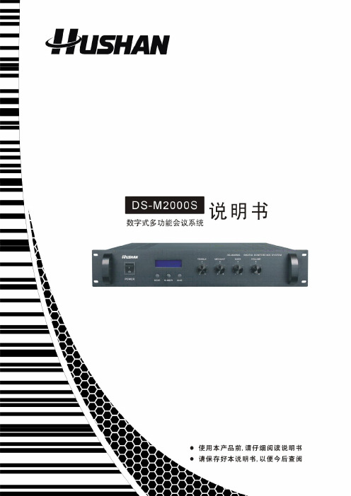
本系统功能全面,既能依据使用者的不同要求采用不同的操作模式来管理会议讨论,又可以与同声传译、有线/无线语言分配系统结合使用。
本系统可以连接电脑进行操作,也可脱离电脑独立工作;可通过主机面板选择系统控制模式:电脑控制模式和主机控制模式。
本主控机功率为415W,单台主机可带60套代表/主席单元,单台主机加扩展的通信能力最多可达到240台。
1.0电脑管理会议系统主控机简介●主控机与会议系统单体连接之数位控制及声音信号采用同一电缆传送(八芯)●可独立运作或是外接电脑结合软体同步联动操作,实现多种会务管理功能(会议模式或操作:指定发言、自由发言、申请发言及先进先出发言等)●单机可实现下列几个会议功能:开放式会议、限制发言、先进先出●系统具有优质声音输出效果●具三种会务管理模式:⏹开放模式⏹先进先出⏹限制发言●可选择同时发言之麦克风数1-9支(含)或全开放式发言●内置视像中央处理器,可实现发言者定位跟踪之功能●面板具有LCD液晶显示,122x32点阵显示会议模式;面板上具有功能键、旋钮供系统设定及调节之用●具音频讯号输出端子,可外接录音或音响设备●具与电话偶合器连接端子,可外接电话偶合器进行电话会议●PELCO-D、Visca协议全兼容●频率响应:40Hz~16KHz;总谐波失真:小于0.1%●消耗功率:415W●采用220V-240V~50Hz-60Hz交流供电●主机净重:11.8kg●外形尺寸:485mm(包括把手)×100mm(2U,包括机箱脚垫)×355mm(W×H×D);可水平放置于台面或安装于19英寸标准机柜中1.2主控机示意图1.电源开关(POWER)2.模式按键(MODE),可选择:自由模式,轮替模式(1-9支),限制模式(1-9支)3.发言人数按键(NUMBER)(1-9支)4.保存键(SA VE)5.LCD显示屏6.系统高音调节电位器(TREBLE)7.系统中音调节电位器(MEDIANT)8.系统低音调节电位器(BASS)9.系统总音量电位器(VOLUME)10、视像切换输入接口(VIDEO INPUT 1-8)11、视频输出接口(VIDEO OUTPUT 1-2)12、电脑数据接口(RS-232)13、高速云球控制接口(RS-232)14、指示灯15、高速云球控制接口(RS-422 / RS-485)16.代表机接线座(LINE)17.系统音频平衡输出端(LINE OUT)18.系统音频不平衡输出端(MIX OUT)19.电话偶合器输入/输出端(TEL)20.数据接口(DATA)21.系统高音增益旋钮(TREBLE GAIN)22.电源插座(220V-240V~50Hz-60Hz)2.0会议单元型号外观外观性能备注台面可移动式,金属底坐可拔插式双软管;自带有一条1.5M连接线。
TC electronic M2000 演播室效果处理器 用户手册 中文官方版

存储(Store)
预置的存储及命名
存储
组合预置的存储和命名
编辑(Edit)
编辑引擎 1 或 2
旁路(BYPASS)
对每个引擎的单独旁路键
二级功能
调用指南 寻找一个适合的预置 删除预置 删除预置的最快(也是唯 一)方法
编辑
引擎混合电平动态渐变
直通
旁路整个设备
快照 1-4
组合预置的快速存储 / 调用
二级功能
如果将 M2000 与非平衡的设备相连,必须将线缆末端的针 1 和 3 并在一起,与非平衡设 备相连。
我们将两个不用的针保留在 MIDI 接口上,作为一个可选的 RS485 接口。因此,如果用 户将 M2000 与其它使用这些针的设备相连,请先确定该线缆是 3 线的标准 MIDI 型号, 而不是 5 线的 MIDIPLUS 型。
调用指南 删除调用
控制部分
OK
确认操作
切换
可以执行“切换的”二级 功能
游标(CURSORS)
在参数间移动
调节轮(ADJUST)
设置参数值和预置号编号
二级功能
取消(CANCEL) 上一页 / 下一页(PAGE UP/DOWN)
7
后面板
主电源开关
注意:
平衡的 平衡的 串行编号 XLR 输入 XLR 输出
M2000 演播室效果处理器 用户手册
M2000
STUDIO EFFECTS PROCESSOR
2
目录
鸣谢
关于此手册,及帮助功能
○
○
○
○
○
○
○
○
○
○
○
○
○
○
○
○
矩阵切换器说明书.(DOC)
shProfessional Matrix矩阵切换器用户手册在使用本系统前,请详细阅读本说明书.并请保管好该手册目录前言 (4)一、清单、外形及安装说明 (5)1、包装清单 (5)2、普通矩阵前后面板 (6)3、数模高清混插矩阵前面板 (7)4、机架安装说明 (10)二、功能特点及主要技术指标 (11)一、普通矩阵 (11)1、功能与用途 (11)2、主要技术指标 (11)二、数模高清混插矩阵 (12)3、功能与用途 (12)2、主要技术指标 (13)三、系统连接图 (15)四、矩阵的操作 (16)1、指示灯及面板按键 (16)2、遥控器的使用 (19)3、显示屏及显示的画面 (20)4、菜单总表及一般操作方法 (22)5、各菜单说明 (24)6、矩阵的切换 (33)7、控制软件 (35)五、注意事项及故障处理 (52)1、注意事项 (52)2、常见故障检修 (52)附录A、串口控制协议 (53)1、通信接口 (53)2、控制命令 (54)附录B、编程说明 (61)1、用 VB 编程控制矩阵 (61)2、用 VC 编程控制矩阵 (62)3、用C# 编程控制矩阵 (64)4、用 Delphi 编程控制矩阵 (66)前言感谢您使用本公司矩阵切换器,使用时请注意以下事项:1.本产品所使用电源必须有电源保护地线,输入、输出设备的电源保护地线要为同一保护地线。
确保设备的输入电源为AC 100~240V/50Hz。
2.使用计算机控制本产品时必须保证控制计算机与本产品的连接电源保护地线是同一个地线。
3.使用本产品时严禁带电插拔输入、输出信号线及RS232 通讯接口线。
4.严禁将本产品放在过热或过冷的地方工作,应保持工作环境通风良好。
严禁将化学物品洒在本产品上。
5.严禁对本产品的机械和电路设计进行更改或增减任何部件,否则厂家对此产生的任何结果不负责任。
6.严禁擅自打开机箱外壳,机器内有交流220V 高压,以免发生触电危险。
矩阵控制操作使用说明书

矩阵操作使用说明书矩阵控制操作使用说明书深圳达实智能股份有限公司2010-8目录一、键盘对视频的选择 (3)二、快球预置位的设置与调用 (3)1、快球预置位的设置: (3)2、快球预置位的调用: (3)三、矩阵的编程和调用 (3)1、系统巡视功能 (4)2、成组切换功能 (5)一、键盘对视频的选择键盘对矩阵控制必须基于监视器的调用,所有功能都必须由键盘先调用一个监视器进行控制,然后再把系统中的某个摄像机的信号切换到该监视器上。
一旦摄像机被调用到监视器上,就可以控制该摄像机上所有的功能,如是快球就可以使用键盘控制快球转动、摄像机对焦、缩放、光圈开关等。
当去控制某个快球时,监视器上出现IN USE并且键盘发出长鸣时说明有别的用户正在控制,当在控制的键盘停止对该快球的控制后,才能对快球进行控制。
摄像机的调用:1)输入需要调用的监视器编号;2)按CLEAR键可以清除键盘上输入的信息;3)按MON键调用该监视器;4)输入需要调用的摄像机编号;5)按CAM键调用该摄像机;数字键数字键二、快球预置位的设置与调用1、快球预置位的设置:选择摄像机,调整好图像,输入自已定义的预置位编号,按【SHOT】键,按住智能键不松,再按【ON】键,最后松开智能键。
调整好图像,进行下一个预置位设置。
2、快球预置位的调用:在数字区输入想要调看的预置图像号码,按【SHOT】键,再按【ACK】键。
如事先没设置该预置图像,监视器图像则无变化。
三、矩阵的编程和调用1、系统巡视功能系统巡视功能是可以通过编程使一系列的画面显示及预置位的调用,或进行成组切换。
通过设定停留时间,可以精确定义每项操作在监视器上显示的时间。
系统巡视的使用:1. 选择想要设置为自由切换的监视器号;2. 输入想要每一摄像机停留的时间(2~240秒);3. 输入自由切换的起始摄像机号;4. 输入自由切换的结束摄像机号。
例如:在3号监视器上切换1-6号摄像机,画面停留2秒:1. 按【 3 】键,再按【MON】键(选择监视器);2. 按【 2 】键(输入自由切换停留时间);3. 稍长时间按住【RUN】键,直到显示屏显示“TIM”时松开键;4. 按【 1 】键,再按【ON】键(起始摄像机号);5. 按【 6 】键,再按【OFF】键(结束摄像机号)。
矩阵切换控制器硬件说明书讲解

矩阵切换控制器硬件说明书注意事项安全注意事项:一、打开矩阵包装,安装前请先根据配件清单,清点包装内的配件是否齐全,如有缺损请及时与厂家或供货商联系,以免由于缺损导致设备无法正常工作。
二、产品的安装和调试应由专业人员操作或在专业人员指导下进行。
三、安装时请考虑安放位置的周围环境因素,注意防尘、防水,以及避免一些剧烈外力、恶劣环境等能够导致设备损伤的因素。
四、第一次使用前,请认真阅读说明书的快速入门部分,避免由于使用不当造成设备无法正常使用或损坏。
五、使用过程中注意保护,避免划伤。
六、切记不要尝试自己拆盖维修,以免造成设备损坏或者其他危险,建议所有维修工作由专门的技术服务人员进行。
七、请使用原厂配件或由制造商推荐的配件。
附件清单:矩阵的包装箱中应该包含以上设备,购买后,请及时清点,如有缺损,请及时与供货商联系,以免影响您的正常使用。
注:所有附件以装箱清单为准。
由于产品功能和设计在不断改进,所以本手册的内容将做不定期的更新,恕不另行通知!目录第一章矩阵接口说明及连接示意图----------------------------------------------11.132路矩阵----------------------------------------------------------11.1.1 接口示意图---------------------------------------------------11.1.2 接口说明-----------------------------------------------------11.1.3 系统连接示意图-----------------------------------------------11.2 64路矩阵、256-16矩阵、256-32矩阵----------------------------------21.2.1 接口示意图---------------------------------------------------21.2.2 接口说明-----------------------------------------------------21.2.3 系统连接示意图-----------------------------------------------3第二章矩阵周边设备接口及连接------------------------------------------------52.1 并行报警主机-------------------------------------------------------52.1.1 接口示意图---------------------------------------------------52.1.2 接口说明-----------------------------------------------------52.1.3 与矩阵连接示意图---------------------------------------------52.2 音频矩阵-----------------------------------------------------------62.2.1 接口示意图---------------------------------------------------62.2.2 接口说明-----------------------------------------------------62.2.3 矩阵连接图---------------------------------------------------6第三章矩阵配套软件----------------------------------------------------------73.1 矩阵设置-----------------------------------------------------------73.1.1 概述---------------------------------------------------------73.1.2 硬件连接、软件登录-------------------------------------------73.1.3 属性设置-----------------------------------------------------83.2 字幕传输----------------------------------------------------------103.2.1 概述--------------------------------------------------------103.2.2 硬件连接、软件登录------------------------------------------103.2.3 属性设置----------------------------------------------------113.3 分控授权----------------------------------------------------------123.3.1 概述--------------------------------------------------------123.3.2 硬件连接、软件登录------------------------------------------123.3.3 属性设置----------------------------------------------------133.4 报警设置软件------------------------------------------------------153.4.1 概述--------------------------------------------------------153.4.2 硬件连接、软件登录------------------------------------------153.4.3 属性设置----------------------------------------------------15第四章系统操作-------------------------------------------------------------174.1 系统简介----------------------------------------------------------17 4.2 矩阵功能及主要特点------------------------------------------------174.3 系统配置与启动运行------------------------------------------------194.3.1 矩阵系统配置-------------------------------------------------194.3.2 系统运行顺序-------------------------------------------------224.3.3 系统运行状态-------------------------------------------------224.4 控制切换说明------------------------------------------------------23 第五章系统布线-------------------------------------------------------------245.1 系统分布----------------------------------------------------------245.2 系统布线----------------------------------------------------------245.2.1 电源线------------------------------------------------------255.2.2 控制/通讯线(RS-485线)-------------------------------------255.2.3 视频布线----------------------------------------------------255.2.4 音频布线----------------------------------------------------255.2.5 报警探头布线------------------------------------------------255.3 布线注意事项------------------------------------------------------26第一章矩阵接口说明及连接示意图1.1 32路矩阵1.1.1 接口示意图【图1-1】1.1.2 接口说明1.视频输入(VIDEO IN):最大32路输入2.视频输出(VIDEO OUT):最大16路输出3.音频输入(AUDIO IN): 最大32路输入4.音频输出(AUDIO OUT): 最大16路输出注:32路A系列矩阵为内置音频切换模块32路C系列矩阵为内置报警输入模块。
矩阵主机操作说明
N o te :
A
B
C
D
Oper ating Distance: 5,0 00 feet( 1.5km)
Boaud Rate: Contro lMethod: Input Voltage:
12 00,2400 ,4800,96 00 RS48 5,RS232 ,RS422 12 VDC 300mA
P OW ER C OD E -A C OD E -B C CT V E Q UIP ME M T F O R C OM M E RC IA L U S E O N L Y
助开关动作。 报警监视器编程 每个警点可通过编程来显示报警图像至指定的监
视器。所有的警点可被定时成自动设防、自动撤防状 态使用。
三、 菜单编程操作 3.0 菜单主选项…………………………………………………………………………………………………………15 3.1 权限菜单……………………………………………………………………………………………………………16 3.1.1 键盘/监视器权限………………………………………………………………………………………………16 3.1.2 键盘/摄像机权限…………………………………………………………………………………………………17 3.1.3 监视器/摄像机权限………………………………………………………………………………………………18 3.1.4 警点/键盘权限……………………………………………………………………………………………………18 3.1.5 网络/监视器权限…………………………………………………………………………………………………18 3.2 切换设置……………………………………………………………………………………………………………19 3.2.1 设置系统程序切换………………………………………………………………………………………………19 3.2.2 设置系统同步切换………………………………………………………………………………………………21
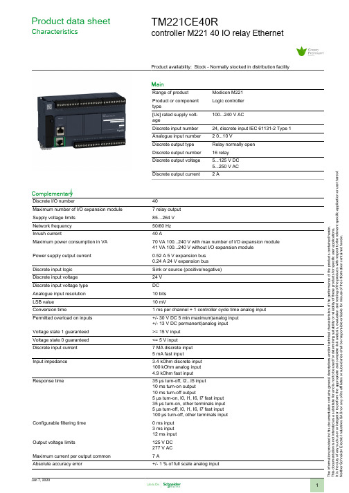
模檬 M221 控制器数据手册说明书
T h e i n f o r m a t i o n p r o v i d e d i n t h i s d o c u m e n t a t i o n c o n t a i n s g e n e r a l d e s c r i p t i o n s a n d /o r t e c h n i c a l c h a r a c t e r i s t i c s o f t h e p e r f o r m a n c e o f t h e p r o d u c t s c o n t a i n e d h e r e i n .T h i s d o c u m e n t a t i o n i s n o t i n t e n d e d a s a s u b s t i t u t e f o r a n d i s n o t t o b e u s e d f o r d e t e r m i n i n g s u i t a b i l i t y o r r e l i a b i l i t y o f t h e s e p r o d u c t s f o r s p e c i f i c u s e r a p p l i c a t i o n s .I t i s t h e d u t y o f a n y s u c h u s e r o r i n t e g r a t o r t o p e r f o r m t h e a p p r o p r i a t e a n d c o m p l e t e r i s k a n a l y s i s , e v a l u a t i o n a n d t e s t i n g o f t h e p r o d u c t s w i t h r e s p e c t t o t h e r e l e v a n t s p e c i f i c a p p l i c a t i o n o r u s e t h e r e o f .N e i t h e r S c h n e i d e r E l e c t r i c I n d u s t r i e s S A S n o r a n y o f i t s a f f i l i a t e s o r s u b s i d i a r i e s s h a l l b e r e s p o n s i b l e o r l i a b l e f o r m i s u s e o f t h e i n f o r m a t i o n c o n t a i n e d h e r e i n .Product data sheetCharacteristicsTM221CE40Rcontroller M221 40 IO relay EthernetProduct availability: Stock - Normally stocked in distribution facilityMainRange of product Modicon M221Product or component typeLogic controller [Us] rated supply volt-age100...240 V ACDiscrete input number 24, discrete input IEC 61131-2 Type 1Analogue input number 2 0...10 VDiscrete output type Relay normally open Discrete output number 16 relay Discrete output voltage 5...125 V DC 5...250 V AC Discrete output current2 AComplementaryDiscrete I/O number40Maximum number of I/O expansion module 7 relay output Supply voltage limits 85…264 V Network frequency 50/60 Hz Inrush current40 AMaximum power consumption in VA 70 VA 100...240 V with max number of I/O expansion module 41 VA 100...240 V without I/O expansion module Power supply output current 0.52 A 5 V expansion bus 0.24 A 24 V expansion bus Discrete input logic Sink or source (positive/negative)Discrete input voltage 24 V Discrete input voltage type DC Analogue input resolution 10 bits LSB value 10 mVConversion time1 ms per channel + 1 controller cycle time analog input Permitted overload on inputs +/- 30 V DC 5 min maximum)analog input +/- 13 V DC permanent)analog input Voltage state 1 guaranteed >= 15 V input Voltage state 0 guaranteed <= 5 V input Discrete input current 7 MA discrete input 5 mA fast input Input impedance3.4 kOhm discrete input 100 kOhm analog input4.9 kOhm fast inputResponse time35 µs turn-off, I2...I5 input 10 ms turn-on output 10 ms turn-off output5 µs turn-on, I0, I1, I6, I7 fast input 35 µs turn-on, other terminals input 5 µs turn-off, I0, I1, I6, I7 fast input 100 µs turn-off, other terminals input Configurable filtering time0 ms input 3 ms input 12 ms input Output voltage limits125 V DC 277 V AC Maximum current per output common 7 AAbsolute accuracy error+/- 1 % of full scale analog inputElectrical durability100000 Cycles AC-12, 120 V, 240 VA, resistive100000 Cycles AC-12, 240 V, 480 VA, resistive300000 Cycles AC-12, 120 V, 80 VA, resistive300000 Cycles AC-12, 240 V, 160 VA, resistive100000 Cycles AC-15, cos phi = 0.35, 120 V, 60 VA, inductive100000 Cycles AC-15, cos phi = 0.35, 240 V, 120 VA, inductive300000 Cycles AC-15, cos phi = 0.35, 120 V, 18 VA, inductive300000 Cycles AC-15, cos phi = 0.35, 240 V, 36 VA, inductive100000 Cycles AC-14, cos phi = 0.7, 120 V, 120 VA, inductive100000 Cycles AC-14, cos phi = 0.7, 240 V, 240 VA, inductive300000 Cycles AC-14, cos phi = 0.7, 120 V, 36 VA, inductive300000 Cycles AC-14, cos phi = 0.7, 240 V, 72 VA, inductive100000 Cycles DC-12, 24 V, 48 W, resistive300000 Cycles DC-12, 24 V, 16 W, resistive100000 Cycles DC-13, 24 V, 24 W, inductive (L/R = 7 ms)300000 cycles DC-13, 24 V, 7.2 W, inductive (L/R = 7 ms)Switching frequency20 switching operations/minute with maximum loadMechanical durability20000000 cycles relay outputMinimum load1 mA 5 V DC relay outputProtection type Without protection 5 AReset time1 sMemory capacity256 kB user application and data RAM 10000 instructions256 kB internal variables RAMData backed up256 kB built-in flash memory backup of application and dataData storage equipment 2 GB SD card optional)Battery type BR2032 lithium non-rechargeable 4 year(s)Backup time 1 year 77 °F (25 °C) by interruption of power supply)Execution time for 1 KInstruction0.3 ms event and periodic taskExecution time per instruction0.2 µs BooleanExct time for event task60 µs response timeMaximum size of object areas8000 %MW memory words255 %TM timers512 %KW constant words255 %C counters512 %M memory bitsRealtime clock WithClock drift<= 30 s/month 77 °F (25 °C)Regulation loop Adjustable PID regulator up to 14 simultaneous loopsCounting input number 4 fast input (HSC mode) 100 kHz 32 bitsCounter function Single phaseA/BPulse/directionIntegrated connection type USB port mini B USB 2.0Non isolated serial link serial 1 RJ45 RS232/RS485Ethernet RJ45Supply Serial)serial link supply 5 V, <200 mATransmission rate 1.2...115.2 kbit/s (115.2 kbit/s by default) 49.21 ft (15 m) RS4851.2...115.2 kbit/s (115.2 kbit/s by default) 9.84 ft (3 m) RS232480 Mbit/s USBCommunication port protocol USB port USB - SoMachine-NetworkNon isolated serial link Modbus master/slave - RTU/ASCII or SoMachine-NetworkEthernetPort Ethernet10BASE-T/100BASE-TX 1 328.08 ft (100 m) copper cableCommunication service DHCP clientModbus TCP clientEthernet/IP adapterModbus TCP serverModbus TCP slave deviceLocal signalling PWR 1 LED green)RUN 1 LED green)Module error (ERR) 1 LED red)SD card access (SD) 1 LED green)BAT 1 LED red)I/O state 1 LED per channel green)SL 1 LED green)ACT Ethernet network activity green)Link (Link Status) Ethernet network link yellow)Electrical connection Removable screw terminal block for inputsRemovable screw terminal block for outputsTerminal block, 3 for connecting the 24 V DC power supplyConnector, 4 for analogue inputsMini B USB 2.0 connector for a programming terminalMaximum cable distance between devices Shielded cable <32.81 ft (10 m) fast inputUnshielded cable <98.43 ft (30 m) outputUnshielded cable <98.43 ft (30 m) digital inputUnshielded cable <3.28 ft (1 m) analog inputInsulation Between input and internal logic 500 V ACNon-insulated between analogue input and internal logicNon-insulated between analogue inputsBetween supply and ground 1500 V ACBetween sensor power supply and ground 500 V ACBetween input and ground 500 V ACBetween output and ground 1500 V ACBetween supply and internal logic 2300 V ACBetween sensor power supply and internal logic 500 V ACBetween output and internal logic 2300 V ACBetween Ethernet terminal and internal logic 500 V ACBetween supply and sensor power supply 2300 V ACMarking CESensor power supply24 V DC 250 mA supplied by the controllerMounting support Top hat type TH35-15 rail IEC 60715Top hat type TH35-7.5 rail IEC 60715Plate or panel with fixing kitHeight 3.54 in (90 mm)Depth 2.76 in (70 mm)Width 6.30 in (160 mm)Net weight 1.01 lb(US) (0.456 kg)EnvironmentStandards EN/IEC 60664-1EN/IEC 61131-2EN/IEC 61010-2-201Product certifications DNV-GLEACABSCULusLRRCMCSAIACS E10Environmental characteristic Ordinary and hazardous locationResistance to electrostatic discharge8 KV in air EN/IEC 61000-4-24 kV on contact EN/IEC 61000-4-2Resistance to electromagnetic fields9.14 V/M (10 V/m) 80 MHz...1 GHz EN/IEC 61000-4-32.74 V/M (3 V/m) 1.4 GHz...2 GHz EN/IEC 61000-4-30.91 V/m (1 V/m) 2...2.7 GHz EN/IEC 61000-4-3Resistance to magnetic fields98.43 A/m (30 A/m) 50/60 Hz EN/IEC 61000-4-8Resistance to fast transients2 KV EN/IEC 61000-4-4 power lines)2 KV EN/IEC 61000-4-4 relay output)1 KV EN/IEC 61000-4-4 I/O)1 KV EN/IEC 61000-4-4 Ethernet line)1 kV EN/IEC 61000-4-4 serial link)Surge withstand2 KV power lines (AC) common mode EN/IEC 61000-4-52 KV relay output common mode EN/IEC 61000-4-51 KV I/O common mode EN/IEC 61000-4-51 KV shielded cable common mode EN/IEC 61000-4-50.5 KV power lines (DC) differential mode EN/IEC 61000-4-51 KV power lines (AC) differential mode EN/IEC 61000-4-51 KV relay output differential mode EN/IEC 61000-4-50.5 kV power lines (DC) common mode EN/IEC 61000-4-5Resistance to conducted disturbances10 V 0.15...80 MHz EN/IEC 61000-4-63 V 0.1...80 MHz Marine specification (LR, ABS, DNV, GL)10 V spot frequency (2, 3, 4, 6.2, 8.2, 12.6, 16.5, 18.8, 22, 25 MHz) Marine speci-fication (LR, ABS, DNV, GL)Electromagnetic emission Conducted emissions 79 dBμV/m QP/66 dBμV/m AV power lines (AC))0.15…0.5 MHz EN/IEC 55011Conducted emissions 73 dBμV/m QP/60 dBμV/m AV power lines (AC))0.5…300 MHz EN/IEC 55011Conducted emissions 120...69 dBµV/m QP power lines)10…150 kHz EN/IEC55011Conducted emissions 63 dBμV/m QP power lines)1.5…30 MHz EN/IEC 55011Radiated emissions 40 dBμV/m QP class A 10 m)30…230 MHz EN/IEC 55011Conducted emissions 79...63 dBμV/m QP power lines)150…1500 kHz EN/IEC55011Radiated emissions 47 dBμV/m QP class A 10 m)200…1000 MHz EN/IEC 55011 Immunity to microbreaks10 msAmbient air temperature for operation14…131 °F (-10…55 °C) horizontal installation)14…95 °F (-10…35 °C) vertical installation)Ambient air temperature for storage-13…158 °F (-25…70 °C)Relative humidity10…95 %, without condensation in operation)10…95 %, without condensation in storage)IP degree of protection IP20 with protective cover in placePollution degree<= 2Operating altitude0...6561.68 ft (0...2000 m)Storage altitude0.00…9842.52 ft (0…3000 m)Vibration resistance 3.5 mm 5…8.4 Hz symmetrical rail3.5 mm 5…8.4 Hz panel mounting1 gn 8.4…150 Hz symmetrical rail1 gn 8.4…150 Hz panel mountingShock resistance98 m/s² 11 msOrdering and shipping detailsCategory22533 - M2XX PLC & ACCESSORIESDiscount Schedule MSXGTIN00785901108979Package weight(Lbs)0.86 kg (1.9 lb(US))Returnability YesCountry of origin TWOffer SustainabilitySustainable offer status Green Premium productCalifornia proposition 65WARNING: This product can expose you to chemicals including: Lead and leadcompounds which is known to the State of California to cause Carcinogen & Re-productive harm. For more information go to REACh Regulation REACh DeclarationREACh free of SVHC YesEU RoHS Directive Pro-active compliance (Product out of EU RoHS legal scope)EU RoHS Decla-rationMercury free YesRoHS exemption information YesChina RoHS Regulation China RoHS DeclarationEnvironmental Disclosure Product Environmental ProfileCircularity Profile End Of Life InformationWEEE The product must be disposed on European Union markets following specificwaste collection and never end up in rubbish bins.Dimensions Drawings DimensionsMounting and Clearance Mounting on a RailDirect Mounting on a Panel Surface(1)Install a mounting stripMounting Hole LayoutMountingCorrect Mounting PositionAcceptable Mounting PositionIncorrect Mounting PositionClearanceProduct data sheetTM221CE40RConnections and SchemaDigital InputsWiring Diagram (Positive Logic)(*)Type T fuseWiring Diagram (Negative Logic)(*)Type T fuseConnection of the Fast InputsI0, I1, I6, I7Relay OutputsNegative Logic (Sink)(*)Type T fuse(1)The COM0, COM1, COM2 and COM3 terminals are not connected internally.(2)To improve the life time of the contacts, and to protect from potential inductive load damage, you must connect a free wheeling diode inparallel to each inductive DC load or an RC snubber in parallel of each inductive AC loadB Sink wiring (negative logic)Positive Logic (Source)(*)Type T fuse(1)The COM0, COM1, COM2 and COM3 terminals are not connected internally.(2)To improve the life time of the contacts, and to protect from potential inductive load damage, you must connect a free wheeling diode inparallel to each inductive DC load or an RC snubber in parallel of each inductive AC loadA Source wiring (positive logic)Analog InputsThe (-) poles are connected internally.Ethernet ConnectionUSB Mini-B ConnectionSL1 ConnectionSL1N.C.: not connected* : 5 Vdc delivered by the controller. Do not connect.Product data sheet Performance Curves TM221CE40RDerating CurvesEmbedded Digital Inputs (No Cartridge)X :Ambient temperature Y :Input simultaneous ON ratioEmbedded Digital Inputs (with Cartridge)X :Ambient temperature Y :Input simultaneous ON ratio。
专业矩阵切换器使用手册(DOC 28页)

User’s manual专业矩阵切换器使用手册Professional Matrix Series Rev.1.2注意:●《专业矩阵切换器用户手册》以其中一个矩阵型号为例作为使用说明,并可作为其它型号的矩阵用户手册。
●本手册只作为用户操作指示,不作为维修服务用途。
●本手册是矩阵切换器的通用手册,实际使用可能会与本手册的内容有出入,这种情况将不属错漏,将根据实际情况另作书面说明。
安全操作指南为确保设备可靠使用及人员的安全,在安装,使用和维修时,请遵守以下事项:1.系统接地。
系统必须有完善的接地,否则,不仅造成讯号干扰,不稳定或机械损坏,而且还可能因漏电引起人身事故;请使用标准的三线电源插座,其地线接地电阻应小于1Ω。
2.禁止改变原设计。
禁止对本产品的机械和电器设计更改或增添任何部件。
否则。
本公司对由此所带来的后果不负责任。
3.请勿使用两芯插头,确保设备的输入电源为220V50Hz的交流电。
4.机器内有220V高压部件,请勿打开机壳,以免触电。
5.不要将机器置于过冷或过热的地方。
6.设备电源在工作时会发热,因此要确保工作环境的良好通风。
以免温度过高而损坏机器。
7.阴雨潮湿天气或长时间不用时,应关闭设备电源总闸。
8.在下列操作之前一定要将设备的交流电源线从交流供电电源插座拔下:a.取下或重装设备的任何部件。
b.断开或重接设备的任何电器插头或其它连接。
9.非专业人士未经许可,请不要拆开机箱,不要私自维修,以免发生意外事故或加重设备的损坏程度。
10.不要将任何化学品或液体洒在设备上或其附近。
目录一、产品简介 (5)1、关于DVI、RGB、VGA、AV、系列矩阵切换器 (5)2、矩阵的型号、规格 (8)3、信号输入,输出端口说明 (9)4、远端控制及通讯接口说明 (9)二、矩阵面板示意图及矩阵系统的安装 (9)1、矩阵前后面板示意图 (9)2、设备接线:a. RGBHV连接线 b. 音频连接线 (14)3、VGA/RGB长线驱动器的连接 (15)4、矩阵与控制电脑的连接 (15)三、前面板功能键 (16)1、切换指令 (16)2、UP、Down状态查询指令 (16)3、SAVE存储指令 (16)4、RECALL调用指令 (16)5、CANCEL键 (16)一、《MATRIX 2.01》矩阵控制软件 (17)二、R S232通讯协议 (21)三、产品技术参数 (23)一.产品简介1.1关于DVI系列矩阵切换器DVI矩阵切换器,是一款高性能的电脑信号专业切换设备,用于多个DVI电脑信号输入输出交叉切换,提供独立的DVI输入、输出端子,每路DVI分量信号单独传输、单独切换,使信号传输衰减降至最低,图像和声音信号能高保真输出。
3M M2000 Intelligent Manometer手册说明书

Quick Start GuideM2000 Smart Manometer & Sensors10920 Madison Ave.Cleveland Ohio 44102 USA + 1 216 281 (800) 817-7849A trusted leader in measurement and calibration solutions.First things firstGeneral purpose use onlyM2000 Smart ManometerMST SensorsThese are not intended for hazardous locations.Steps to get started Make a connection▪Attach the pressure fittings to the internal pressure sensor module.▫The threads should be coated with a pipesealant compound before installation. ▫Tighten to finger tight plus 1.5 turns to 3turns using a 19 mm (3/4 in.) wrench on themanifold.Use only a wrench on the fittingand the manifold.▪Optional: Attach the pressure fittings to theexternal pressure sensor module.▪Optional: Attach the RTD cable and probe to anRTD module.Carefully equalize the pressureTo avoid damaging differential sensors:1. Make sure you are connecting to the correctpressure port on DN or DI differential pressure modules.1. P1 port is high pressure.2. P2 port is low pressure.2. Apply pressure to both differential ports (P1 andP2) at the same time.Know your batteriesThe Smart Manometer is powered by four 1.5 volt AA size batteries.▪Never mix batteries—not by manufacturer or bysize, by capacity, or by chemistry. ▪Never mix old and new batteries.▪Remove all four batteries in the M2000 at thesame time.▪Replace all four batteries with batteries from thesame package or with the same expiration date.Install the batteries1.Turn over the Smart Manometer so the display faces down.2. Remove the two screws on the battery coverwith the Phillips head screwdriver by turning them counterclockwise.3. Insert four AA batteries.Note: Pay attention to the positive (+) and negative (−) battery polarity markings at the bottom of the compartment.4. Replace the battery cover. To secure the cover,torque the screws clockwise 2 in. lbs. maximum.Learn the function keysMeriam Tethered Sensors (MTS)Optional Meriam Tethered Sensors▪Pressure (Absolute, Compound, Differential).▪Temperature (RTD PT100).Make an electrical connection▪Align the red dot on the Smart Manometer with the red dot on the Tether cable and push in.▪Align the red dot on the MTS with the red dot on the Tether cable and push in.USB cable & meriSuite CGFor use only in non-hazardous locationsConnect the USB cable to the Smart Manometer and to your computer to configure the M2000 and sensors using the meriSuite CG application.Install USB Drivers & meriSuite CGYou must install USB Drivers first then install the meriSuite CG application.For installation instructions:https:///resources/download/Open meriSuite CGUse meriSuite CG application to:▪Sync PC Time to Gauge for data logging anddisplay.▪Select or deselect the Display functions oneach Smart Manometer or Measurement Units that you need on each sensor.▪Select the timeout for the Backlight and for theAuto Off.Close meriSuite CG▪Do not turn off the power on the M2000 while it is communicating with meriSuite CG.▪Close meriSuite CG first, disconnect the USB, and turn off the Smart Manometer.1. Backward2. Home3. Forward4. Units5. Start6. Stop7. Up arrow 8. Left arrow 9. Zero or Tare 10. Right arrow 11. Down arrow 12. Cancel or Escor ×13. Accept or ✓14. Power15. Information 16. BacklightThe keys from left to rightFrequently Asked QuestionsFAQsHow often is a new pressure measurement displayed?The calibrator display updates with a new pressure measurement five times per second.What are the different Display functions on the calibrator?The calibrator ships with five functions turned on. They are listed in bold below. Turn functions on or off using meriSuite CG.1. Home (default)7. AVG(Average)2. MIN(Minimum)8. RATE3. MAX(Maximum)9. DATA LOG4. RELIEF VALVE TEST10. Temperature & Time5. + / - (Accuracy)11. LEAK TEST6. T.OFF, T.ON(Tare)12. LEAK TESTDURATIONWhat does it mean when the red backlight flashes?▪The flashing red backlight indicates an error condition.▪Possible error conditions are:▫Pressure has exceeded the stated upper limit of the sensor(s).▫Pressure has fallen below the stated lower limit of the sensor(s).▪The red backlight overrides the white backlight.FAQsWhat does the Zero (Ø) key do?Home▪If the sensor is within a tolerance band aroundzero, press and hold the Zero key to zero thepressure measurement and to reset the Minand Max measurements.▪Note: The tolerance band is approximately ± 1% of the Full Scale pressure value of the sensor.▪Absolute sensors have additional functionality.In Min or Max mode▪Press and hold the Zero key to reset the Minand Max measurement. However, this does notzero the pressure measurement.In Tare mode▪When the Tare is off (T.OFF), press and holdthe Zero key to turn on Tare (T.ON) and toset the Tare value at the current p ressuremeasurement.▪Likewise, when the Tare is on (T.ON), press andhold the Zero key to turn off the Tare mode.In Average mode▪Press and hold the Zero key to restart therolling average.Holding the Zero key▪The key must be held to perform the Zero orTare mode. The displayed value(s) dashes outduring the zero or tare process.Why are the available units differentbetween a 15 psi and 3 000 psi sensor?If a given measurement unit cannot displaythe correct number of digits, the calibratorautomatically advances to the next displayable unit.FAQsWhich version of Data Log is on mycalibrator?1. Turn on the calibrator.2. Press the Display button until DATA LOGappears.3. Press the Information button. The versionappears: Vers. Pro or Vers. Lite.How long does the white backlight stayon after the Backlight key is pressed?▪The white backlight has an automatic timeout.If no keys have been pressed, the backlightautomatically turns off after 1 minute.▪Note: You can configure the backlight timeoutwith meriSuite CG.What does the bar graph at the top of thedisplay indicate?▪The bar graph displays a live indication of thecurrent pressure applied to the sensor as a % ofFull Scale.▪However, when the battery percentage isdisplayed, the bar graph follows the large digitdisplay in indicating the remaining state ofcharge for the batteries.What does low battery indicator mean?▪Be prepared to change batteries when yousee the outline of the battery icon or when theoutline of the icon flashes.FAQsHow long will the calibrator remain on ifI leave it unattended?▪The default setting is Always On.▪You can configure the timeout for Auto Off withmeriSuite CG.How to contact usContact SalesIf you have any issues, questions, or suggestions,please contact us using one of the followingmethods.****************Meriam®10920 Madison AveCleveland Oh io 44102 USA+ 1 216 281 1100(800) 817-7849。
C2000安全光栅手册范文

f安全光栅C2000多光束光电安全开关M2000技术手册1关于本说明书1.1本说明书的简介本说明书提供了安全光栅C2000系列、多光束光电安全开关M2000系列、可测试的光电安全开关和控制器LE20的相关资料。
主要内容包括:∙安全∙设置与操作∙应用∙产品接口∙维护1.2本说明书的服务对象以下人员可参阅此说明书:∙机器设计人员∙工厂计划人员∙用户∙负责安全的官员∙维护人员1.3本说明书的内容本说明书包括使用、订货和维护所必需的资料。
详述了传感器的工作原理,应用及安装方法。
如需更多的资料可直接向施克(SICK)光电公司中国/香港办事处索取。
1.4本说明书中用到的标记本说明书中用一些符号来标记一些应引起注意的重要信息:注释产品的一些特殊性能的说明说明为更好地理解产品某方面的技术性能而提供的一些背景资料建议建议用户应采取的最好措施警告信息!注意警告标记,避免发生意外事故。
2使用安全须知2.1专家指导为保证安全,安装和电气接线只能由具有相关知识的专业人士进行。
针对各个环节,需要以下技能:2.1.1安装∙具有机械安装经验∙熟悉车间现有的安全标准2.1.2电气接线∙具有电气接线经验∙熟悉现有的电气安全标准2.1.3测试与初始启动有些国家和地区要求测试与初始启动必须由专业人士来进行。
2.1.4操作操作者在使用光电安全设备前,必须由有关专家进行指导培训。
2.2装置的使用2.2.1 C2000、M2000和可测试的光电安全开关安全光栅C2000是用来对机器和设备周围的危险区进行手臂安全保护的。
多光束光电安全开关M2000和可测试的光电安全开关是用来防止人员进入机器和设备周围的危险区。
因此,这些安全装置必须安装于危险区的入口处。
当至少有一条光束被遮断时,机器的危险动作就会被停止。
注释:C2000和M2000可单独使用,也可和安全控制装置、紧急停机装置或控制器LE20 一起使用组成完整的安全控制系统。
可测试的光电安全开关用做安全功能时,必须和控制器LE20一起使用。
HDMI 4x2 矩阵开关器 用户手册说明书

HDMI® 4x2 Matrix Switcher with Dual Audio De-embedder, ARC & 4K UltraHDUser Manual v1.1All rights reserved 20151.IntroductionThis is a high performance HDMI Matrix with four HDMI inputs & two outputs, it allows any source (Blue-Ray player, HD DVD player, satellite receiver, game system, etc.) to be shown on the any of the two displays simultaneously, and supports 4K×2K, 3D, 12-bit Deep Color. With its 3Gbps bandwidth and the additional features of the latest HDMI standards you can be sure of great HDMI distribution. It support dual ARC and wide band IR extend function also.2.FeatureCompliant with HDMI 1.4,HDCP 1.4Supports multiplexed HDMI 4-input and 2-outputSupports video format up to 4k2k@30Hz with 24bit RGB/YCbCr 4:4:4/YCBCR 4:2:2, and up to 4k2k@60Hz with 12bit YCBCR 4:2:0.Deep Color support 48/36/30/24-bitSupports reception of any audio data conforming to the HDMI specification such PCM at up to 192kHz, compressed audio (IEC 61937), DSD, DST, DTS and HBR.Supports Dual ARC controlSuper wideband IR control system, IR transport channel can be forward or backward. Supports button,IR,RS232 etc various controlled ways;3.Package Contents4x2 HDMI Matrix 1pc5V/1A DC power adaptor 1pcRemote Control 1pcOperation Manual 1pcWideband IR Tx 4pcWideband IR Rx 2pcRS232 Cable 1pc4.SpecificationVideo Bandwidth297MHz/2.97 GbpsInput Ports 4 × HDMI (Female type)Output Ports 2 × HDMI (Female type)Output Resolution480i ~1080p50/60, 4Kx2K@24/30, VGA~UXGAHDMI Cable in1080p/12bits (15m)HDMI Cable out1080p/12bits (15m)ESD Protection±8 kV (air-gap discharge)Human Body model: ±4 kV (contact discharge)Power Supply 5 V/1A DC (US/EU standards, CE/FCC/UL certified) Dimensions113 mm (W) × 260 mm (D) × 26 mm (H)Weight750 gChassis Material MetalSilkscreen Color BlackOperating Temperature0 °C~40 °C/ 32 °F~104 °FStorage Temperature−20 °C ~ 60 °C/−4 °F ~140 °FRelative Humidity20~90 % RH (non-condensing)Power Consumption 2.0 W5.Operation and Functions5.1 Front panel1.ON/OFF: Power on/off switch.2.POWER LED: This red LED illuminates when the device is connected with powersupply.3.IR: Remote control receiver window.4.OUT A: These red LED illuminates when the output A channel select to thecorresponding input.5.OUT B: These red LED illuminates when the output B channel select to thecorresponding input.6.ARC: Press this button to select OUT A or OUT B Coaxial audio from source or HDTV. ARC function: If you need use ARC, your HDTV must support this function, when you open the ARC function, the Coaxial of the matrix will output the HDTV current display content audio. Otherwise will output the matrix input source audio.7.RST BUTTON: Press this button the matrix setting will recover to factory state.5.2 Rear panel1.RS232: Connect the RS232 port to the PC or notebook by RS232 Cable to control thematrix.2.Input:This slot is where you connect the HDMI source output from Blu-ray, PS4,Set-top Box or a laptop.3.IR TX: Connect the IR Blaster cable included in the package for IR signal transmission.Pace the IR blaster in direct line-of-sight of the equipment to be controlled.4.IR RX: Connect to the IR Receiver for IR signal reception. Ensure that remote beingused is within the direct line-of-sight of the IR receiver.5.OUT B:The HDMI is where you connect the HDTV or monitor with HDMI cable forinput source display. The Coaxial audio output is where you connect to the amplifier with coaxial cable.6.OUT A:The HDMI is where you connect the HDTV or monitor with HDMI cable forinput source display. The Coaxial audio output is where you connect to the amplifier with coaxial cable.7.DC 5V: Plug the 5V1A DC power supply into the unit and connect the adaptor to ACwall outlet.5.3 Connect and Operate1. Connect the signal sources such as Blu-Ray Players, Play Station 3, audio/video receiver, satellite receivers and computers equipped with HDMI output interfaces with a short high-speed HDMI cable to the HDMI Matrix inputs.2. Connect the HDMI output from the HDMI Matrix to a high-definition display device such as HDTV, 4K Ultra HDTV or projectors with HDMI input interfaces. Use high-speed HDMI cables that are recommended for the distances that are required for each connection.3. The Matrix is powered by an external power supply that is included. Connect power first to the source, then to the Matrix and then to each HD TV or projector.4. The input source can be controlled from the display. This is accomplished by using an optional IR Receiver pigtail pointing away from the display(s), which can be connected with the optional HDMI IR Adapter, and inserted between the HDMI cable connector and the display with the toggle switcher at the “IR” posit ion. The IR Transmitter pigtail is then connected to the Matrix and pointed to the source(s). A remote control is used at the display to select switch inputs and output. The matrix also has the capability of being controlled via Remote control.5.4 Wideband IR (30 KHz---60 KHz) introductionIR BLASTER (TX)To control the source:Plug IR Blaster into IR TX port of transmitter unit; place blaster in front of the IR eye of the source.IR RECEIVER (RX)To control the source:Plug IR Receiver into IR RX port of receiver unit; place receiver at or near display.6.Remote ControlOUTPUT A: Press IN1\IN2\IN3\IN4 button will fast switch to selectinput source to HDMI OUTPUT A, and the LED will indicate thecorresponding input source. Press button OUTPUT A will cyclefrom input IN1\IN2\IN3\IN4.OUTPUT B: Press IN1\IN2\IN3\IN4 button will fast switch to selectinput source to HDMI OUTPUT B, and the LED will indicate thecorresponding input source. Press button OUTPUT B will cyclefrom input IN1\IN2\IN3\IN4.7. RS-232 Control guide using a PCInstallationThe PC controller is green software. Just use a cable to connect the PC via RS232 port and copy “4x2 HDMI matrix Controller.exe” to PC to complete installation.Preparation1. Connect PC and multi-viewer by RS232 cable2. Power-up multi-viewer3. Double click 4x2 HDMI matrix Controller.exe icon to run itGeneral Page1.Select RS232 COM port2.Click to connect or disconnect PC and Matrix3.Click to refresh device status: include device information and Input/Output Settings on“Matrix” page4.Click to clear device information5.Click to reset to the factory settingsEDID PageThe controller has 3 methods to set the EDID mode. Manual mode, Copy mode and open EDID file mode.1.Select the needed EDID to input port and click set button the EDID will write to theselected HDMI input ports.2.Copy the selected HDMI output or HDBT output EDID and click set button to write tothe selected HDMI input ports.3.Open the user define EDID file and click set button to write to the selected HDMI inputports.4.Click the status button to refresh input EDID status.Matrix Page1.LED which display Input number for respective Output2.Click to select Input port for respective Output port3.Click to select previous or next Input port for respective Output port4.Click to open or close output ARC functionFirmware Upgrade Page1.Click to open FW file (file extension is “.fw”)2.Click to upgrade the Matrix software3.Display the message of the software upgrade process.8.Connection DiagramWarrantyB.KanexPro TM warrants that (a) its products (the “Product”) will perform greatly inagreement with the accompanying written materials for a period of 3 years from the date of receipt and (b) that the product will be free from defects in materials and workmanship under normal use and service for a period of 1 year.C.Customer RemediesKanexPro entire liability and Customer’s exclusive remedy shall be, at KanexPro option, either return of the price paid for the product, or repair or replacement of the Product that does not meet this Limited Warranty and which is returned to Kanex Pro with a copy of customers’ receipt. This Limited Warranty is void if failure of the Product has resulted from accident, abuse, or misapplication. Any replacement Product will be warranted for the remainder of the original warranty period or 90 days whichever is longer.D.NO LIABILITY FOR DAMAGESTo the maximum extent permitted by applicable law, kanex Pro disclaims all other warranties, either express or implied, including, but not limited to implied warranties of merchantability and fitness for a particular purpose, with regard to product and any related written materials. This limited warranty gives customers specific legal rights. Customers may have other rights depending on the jurisdiction.E.NO LIABILITY FOR DAMAGESTo the maximum extent permitted by applicable law, in no event shall Kanex Pro be liable for any damages whatsoever (Including without limitation, special, incidental, consequential, or indirect damages for personal injury, loss of business profits, business interruption, loss of business information, or any other pecuniary loss) arising out of the use of or inability to use this product, even if Kanex pro has been advised of the possibility of such damages.SupportKanexPro Technical and Customer support inquiries can be sent electronically via the following avenues:Tech Support Inquiry: /support/Email: ********************KanexPro Customer support can be reached via phone at (888) 975-1368 (International Calls: 1-714-332-1682) during the following times:Monday – Friday: 6:00 am – 5:00 pm PST。
矩阵控制器M2000说明书k210中性

2安装、连接、设置、通电、指示灯警告:●全中文矩阵系统不能擅自拆离前面板,如用户拆离,擅自连线会影响通讯及程序。
●安装要由有资格的服务人员进行,并应当遵守相应规定。
必须避免无关人员不当引起故障。
并且维护人员要预先考虑,避免由于掉落物,外来人员破坏,建筑物振动或它相似原因引起故障发生。
●如果您在安装使用过程中遇到疑问和故障时,可向技术服务中心咨询。
一、安装全中文矩阵系统是按EIA标准设计3U机箱结构。
为便于通风和维修时的方便,安装时机箱的背面与墙的最小距离应不小于1米,并且全中文矩阵系统与任何其它设备之间应保持有0.5米的间距,安装人员应当确保有适当的气流流过机箱,以提供足够的通风条件。
二、连接系统中所有的连接器均设置在各机箱的后面板上。
为保证全部连接的正常完成,应在系统中所有设备都未通电时进行。
后面板连接如下图:2.1视/音频输出的连接视频输出插座设置在机箱的后面板,即标有数字(CON1-20)的那些DB15连接器,插上视频排线(带8个BNC插头)的BNC插头,其上都标清了输出序号,可接监视器、录像机(VCR)或其他具有75Ω输入阻抗的视频设备。
如果视频输出需要环接多个设备,则可经使用系统的环接输出口进行。
连接如图:视/音频输出2视/音频输出3视/音频输出48个BNC头2.2视/音频输入的连接视频输入连接是指将外部的视频信号接至,即标有数字(CON1-20)的那些DB15连接器,插上视频排线(带8个BNC 插头)的BNC 插头,其上都标清了输入序号。
对于全中文矩阵系统,各视频输入均接有75Ω电阻。
最好使用较高档的视频电缆,并且应遵循制造厂推荐的直接传送信号的最大距离。
视/音频输入1视/音频输入2视/音频输入3视/音频输入48个BNC 头视/音频输入5视/音频输入6视/音频输入7视/音频输入8注意:当传送距离超过300米时,最好应选用视频放大器对图像进行补偿。
视频输入的连接(全中文矩阵系统)对全中文矩阵系统,各视频输入未接有75Ω电阻,如果摄像机输入信号不环接到其他外接的75Ω终端设备,则全中文矩阵系统机箱相应的环接口必须有75Ω输入电阻,否则会造成图像信号过强、发白、字符抖动等现象。
安防技术_GE2000数字矩阵使用说明书
GE2000数字矩阵使用说明书GE2000数字矩阵主要实现监视远程图像、图像上电视墙、参数调节、控制前端云台镜头、录像、远程布/撤防的功能。
网络端连接配置:连接前的准备情况:1,需要安装解码卡驱动,把解码卡安装好。
2,当安装好解码卡后,设置配置路数,根据实际情况配置。
3,要求主机的显卡是64MB或更高,机器的操作系统是WIN2000操作系统,内存最少256MB内存。
4,网络带宽是10MB以上。
以下为操作的基本步骤:打开【开始】-【程序】-【黄金眼M4存储王网控】-【系统配置程序】后,弹出一个对话框,如下图所示:这个对话框是用来配置通道类型的,GE2000数字矩阵是采用的硬解码选择015-硬解码网控,(注:“010-网控A”是软解码的设置,不能进行矩阵切换上电视墙。
)。
设置完点“确定”按钮会弹出“系统配置程序”的登陆对话框,如下图所示选择“用户名和密码”登陆后,会弹出配置对话框,“通道类型”的配置也可在[视频]配置选项卡进行配置,如下图:第一步:在左边的编辑框中选择“视频通道”选项。
第二步:选择[增加]按钮弹出如下对话框,设置如下图所示:注:板卡类型选择“010-软解码网控A”(硬解码的类型)例如,配置4个网络端的视频输入;就增加4个视频通道,最后结果如下图所示注意:不要配置视频源,只需要配置视频通道就可以了,如果配置了视频源,将无法连接图像,系统运行将不正常。
然后选择【网络】页框中,设置用户想要连接的主机(可以设置多台),注意在本地连接中所有的主机都要选择一样的连接方式,不能一台是TCP/IP而别的是UDP方式,配置如下:单元号:主机端配置程序为该系统配置的主机单元号。
在以往的网控程序,连接主机直接通过主机IP,单元号无关紧要,但对于以后的网控系统,单元号设置不正确可能导致连接不上。
主机名:主机名称的助记符,不一定与该主机的网络名称相同,该名称将出现在网控程序左边的视图中。
主机IP:主机的IP地址。
矩阵控制软件使用说明书

深圳昊诚矩阵控制软件说明书V 1.3.81.安装软件1.1先安装光盘中的软件,只需点击下一步即可。
1.2安装完成显示桌面图标。
2. 系统设置当清除设置后或是第一次运行本软件时会出现系统设置对话框,如下图所示:1. 串口号必须是本机系统中存在的空闲串口。
2. 矩阵的出厂默认地址是 0XFE(16进制),也就是十进制的254。
3. 输入数和输出数必须是大于0的正整数。
4. 矩阵类型共分为3种:VGA、RGB、Video。
5. 如果你选购的矩阵可以支持AV切换请选中“支持AV切换”。
3. 主界面主界面如下所示:主界面分为菜单条、右上的切换模式控制以及系统设置和右下的模式管理。
3.1 切换通道比如要把输入2切换到输出3,只要用左键点击一下第2行的第3列的矩形框就行了。
软件默认是显示16行X16列,当矩阵规模的输入数或输出数大于16时就会出现上一页和下一页的按钮。
3.2 关断输出端口要关断那个输出只要对那路输出点击右键,然后点击弹出的右键菜单中的“关断”项就能关断该输出,如果输出端口被关断了颜色就变成红色。
当有输入端口切换到关断的输出时输出端口会自动恢复到打开的状态。
3.3 设置端口名称每个输入或输出端口下面都有一个输入框,在该输入框中可以输入端口的名字用来标识每个端口链接的对象(比如输入端口1连接了摄像头1就可以在1号输入端口的输入框中输入摄像头1)3.4 把某路输入切换到所有输出只要双击某个输入端口的蓝色小筐,就能把该输入端口输出到所有的输出端口。
如下图所示:3.5 设置切换方式该功能只有当矩阵支持AV切换的时候有用。
3.6 系统设置在系统设置曲可以设置用那个串口控制矩阵,以及每个切换命令之间的时间间隔。
3.7 模式管理(1)保存模式,点击“保存模式”按钮会出现如下所示的对话框:输入模式名点击“确定”按钮可以把当前切换状态存成一个模式。
(2)预览模式,当点击该模式的时候可以预览实际的切换效果。
(3)执行模式,如果要执行某个模式,只要选中一个模式然后点击“执行选中的模式”按钮。
盟威矩阵主机说明书

3.1.5 网络/监视器权限…………………………………………………………………………………………………38
3.2 切换设置……………………………………………………………………………………………………………39
3.2.1 设置系统程序切换………………………………………………………………………………………………39
3.3 键盘设置……………………………………………………………………………………………………………43
3.4 监视器设置…………………………………………………………………………………………………………44
3.5 摄像机设置…………………………………………………………………………………………………………45
二、 系统模块 2.1 主控制模块………………………………………………………………………………………………………………4 2.2 视频输入模块……………………………………………………………………………………………………………5 2.3 视频输出模块…………………………………………………………………………………………………………5 2.4 音频输入模块……………………………………………………………………………………………………………5 2.5 音频输出模块……………………………………………………………………………………………………………5 2.6 视频环接模块……………………………………………………………………………………………………………5 2.7 报警模块………………………………………………………………………………………………………………5 2.8 通讯接口………………………………………………………………………………………………………………5
10.3 矩阵主机与解码器连接图…………………………………………………………………………………………14
科迪矩阵控制软件使用说明(支持网络及定时切换)(201012)

科迪矩阵控制软件使用说明第一章软件安装本软件为绿色软件,将该科迪矩阵控制软件目录复制到硬盘上即可。
复制完成后,运行RWMP286.exe。
默认的用户名为:aaa,密码:123第二章软件使用运行RWMP286.exe后,会出现如下界面:(以下图片仅供参考,软件版本以应用软件为准)A切换画面简介:上图中,每一个彩色圆饼处所处的交叉点位置对应一路信号的输入输出关系。
右方为输出信号(即矩阵的目的端口),上方为输入数(即矩阵的源信号端口)。
例如,上图表示输入1切换至输出1,输入2切换至输出2,......,输入16切换至输出16。
当鼠标在屏幕上移动时,对应的输入和输出路数颜色会变化,以示区别,上图中鼠标停留在输入16(in16)和输出14(out14)的位置上。
圆饼被分隔成几部分,就表示矩阵有多少层,上图中圆饼有红色、蓝色两部分,故有视频、音频两层;当只点亮其中一层时,就单独切换该层,若全部点亮,则为多层同时切换。
按钮:状态刷新按钮,点击该按钮,矩阵的所有状态将刷新一遍。
当矩阵规模较大时,刷新时间会较长(几秒至几十秒不等)。
按钮:通过点击该按钮,可以放大或缩小的大小和显示的圆饼个数。
按钮:在预置后,‘切换’为按照预置进行切换;‘取消’为取消预置键。
保存预置设置功能:。
按“增加”键,进行预置,单击鼠标左键,如上图所示,预置切换路数,按“Done”即可按照自己定义的“Name”一栏的名称进行保存。
调用时,单击下拉菜单中选择已经预置的内容,所预置的内容通过“编辑”可以进行修改,并保存。
显示与矩阵之间的通讯数据,供专业人士参考。
B快速使用入门:1、查询矩阵状态:1)单路查询:鼠标左键单击屏幕右侧的输出按键,圆饼的位置就是所对应的输入路数。
2)多路查询:鼠标左键单击状态刷新按钮,所有路的状态将刷新一遍。
2、切换路数:1)单路切换:鼠标左键双击输入、输出的交叉点位置,既将所对应的输入路切换到所对应的输出路。
鼠标左键单击输入、输出的交叉点位置,既将所对应的输入路预置到所对应的输出路,之后按‘切换’键,即实现切换。
大华2门控制器说明书

大华2门控制器说明书1:产品概述本文档是针对大华2门控制器的说明书,旨在为用户提供详细的产品使用指南和操作说明。
2:产品特点2.1 双门控制:支持同时控制两扇门的开关和访问控制。
2.2 多种验证方式:支持刷卡、密码和指纹等多种验证方式,满足不同安全需求。
2.3 高安全性:采用高级加密算法和安全协议,保障系统数据的安全性。
2.4 多样化接口:提供多种接口,方便与其他安全设备的连接和集成。
3:硬件连接3.1 电源接口:将电源适配器连接到控制器的电源输入端口。
3.2 门禁设备接口:将读卡器、按钮和电磁锁等门禁设备连接到控制器的对应接口上。
3.3 网络接口:将控制器与局域网连接,用于远程管理和监控。
4:安装和部署4.1 安装位置选择:选择安装位置,确保设备安全可靠且易于使用。
4.2 设备安装:按照说明书中的步骤将控制器固定在所选择的位置上。
4.3 门禁设备连接:根据需求连接读卡器、按钮和电磁锁等门禁设备。
4.4 网络配置:设置控制器的网络参数,确保与局域网正常通信。
5:系统设置5.1 时间和日期设置:设置控制器的时间和日期信息,保证事件记录的准确性。
5.2 门禁权限设置:设置卡片、密码和指纹等用户的门禁权限,控制其对门禁设备的访问。
5.3 报警设置:设置报警规则和触发条件,响应异常事件并进行相应的报警处理。
5.4 记录查询与导出:查询控制器的开门记录、报警记录等,并可导出相应的记录文件。
6:远程管理6.1 远程监控:通过网络连接,实时监控门禁系统的状态和事件记录。
6.2 远程配置:通过网络连接,便捷地配置设备参数和权限管理。
6.3 远程维护:通过网络连接,远程升级设备固件和进行故障排除。
7:故障排除7.1 门禁设备故障排除:针对不同的故障现象,提供具体的排除方法。
7.2 网络故障排除:针对网络连接异常,提供对应的排除指南。
7.3 系统故障排除:针对系统异常和错误提示,提供相应的排错和解决方案。
8:附件本文档附带以下附件:8.1 大华2门控制器产品规格表8.2 大华2门控制器安装手册8.3 大华2门控制器网络配置指南9:法律名词及注释9.1 《中华人民共和国刑法》:中华人民共和国刑法是中华人民共和国的刑事法律体系的总条例。
(矩阵)安装说明

234235目录使用本说明书的注意事项 (3)第1章产品概况 (4)1.1产品特点 (4)1.2矩阵主机功能 (4)1.1.1键盘控制 (4)1.2.2手动切换 (4)1.2.3自动切换 (4)1.2.4通用切换 (5)1.2.1同步切换 (5)1.2.6群组切换 (5)1.2.7时间切换 (5)1.2.8报警响应 (5)1.2.9屏幕显示 (5)1.1.10控制端口 (5)1.2.11摄像机预置点 (5)1.2.12权限 (6)1.1.13编程方式 (6)第2章技术指标 (7)2.1面板介绍 (7)2.2技术指标 (10)2.2.1中型矩阵的技术指标 (10)2.2.2大型矩阵的技术指标 (11)第3章设备安装 (12)3.1安装 (12)3.2系统框图和典型连接图 (12)3.2.1视频连接 (18)3.2.2控制数据线连接 (18)3.2.3报警输入_输出的连接 (18)3.3通电 (19)3.3.1通电前 (19)3.3.2通电后 (19)第4章操作与编程 (20)4.1操作 (20)4.1.1密码登录 (20)4.1.2手动切换 (20)4.1.3控制前端设备 (21)4.1.4运行一个自动切换 (22)4.1.5运行一个通用切换 (22)4.1.6运行一个同步切换 (22)4.1.7运行一个群组切换 (22)4.1.8运行一个时间切换 (23)4.1.9停止一个已运行切换队列 (23)4.1.10改变切换队列的运行方向 (23)4.1.11控制多画面分割器 (23)4.2非菜单编程 (23)4.2.1字符显示位置调整 (24)4.2.2预置点设置 (24)4.2.3自动切换编程 (24)4.2.4报警编程 (25)4.2.5保存编程数据 (26)4.2.6键盘密码设置 (26)4.3菜单编程 (27)4.3.1菜单结构 (28)4.3.2系统 (28)4.3.3监视器 (32)4.3.2摄像机 (32)4.3.5键盘设置 (33)4.3.6报警 (33)4.3.7权限 (36)第5章附录 (40)5.1中英文对照表 (40)5.2名词解释 (41)5.3电视监控系统常见故障 (42)5.4区位码表 (42)使用本说明书的注意事项功能特点本说明书不适用章节产品名称/图片中型矩阵全功能无小型矩阵无字符叠加和屏幕菜单 4.2.1字符显示位置调整4.2.6中,“密码查询”部分4.3菜单编程大型矩阵主机无并行报警输入、输出需用报警接口箱来实现3.2中,典型连接图2“矩阵主机后面板并行报警输入、输出端口”部分4.2.4中“矩阵主机后面板并行报警输入、输出端口”部分第1章产品概况矩阵切换/控制(主机)系统采用了先进的大规模集成电路矩阵切换技术和计算机控制技术,可以为用户提供卓越的整体性能,它具有完备的视音频矩阵切换能力,可以在任意监视器上显示任意摄像机的图像和与之对应的声音。
- 1、下载文档前请自行甄别文档内容的完整性,平台不提供额外的编辑、内容补充、找答案等附加服务。
- 2、"仅部分预览"的文档,不可在线预览部分如存在完整性等问题,可反馈申请退款(可完整预览的文档不适用该条件!)。
- 3、如文档侵犯您的权益,请联系客服反馈,我们会尽快为您处理(人工客服工作时间:9:00-18:30)。
2安装、连接、设置、通电、指示灯警告:●全中文矩阵系统不能擅自拆离前面板,如用户拆离,擅自连线会影响通讯及程序。
●安装要由有资格的服务人员进行,并应当遵守相应规定。
必须避免无关人员不当引起故障。
并且维护人员要预先考虑,避免由于掉落物,外来人员破坏,建筑物振动或它相似原因引起故障发生。
●如果您在安装使用过程中遇到疑问和故障时,可向技术服务中心咨询。
一、安装全中文矩阵系统是按EIA标准设计3U机箱结构。
为便于通风和维修时的方便,安装时机箱的背面与墙的最小距离应不小于1米,并且全中文矩阵系统与任何其它设备之间应保持有0.5米的间距,安装人员应当确保有适当的气流流过机箱,以提供足够的通风条件。
二、连接系统中所有的连接器均设置在各机箱的后面板上。
为保证全部连接的正常完成,应在系统中所有设备都未通电时进行。
后面板连接如下图:2.1视/音频输出的连接视频输出插座设置在机箱的后面板,即标有数字(CON1-20)的那些DB15连接器,插上视频排线(带8个BNC插头)的BNC插头,其上都标清了输出序号,可接监视器、录像机(VCR)或其他具有75Ω输入阻抗的视频设备。
如果视频输出需要环接多个设备,则可经使用系统的环接输出口进行。
连接如图:视/音频输出2视/音频输出3视/音频输出48个BNC头2.2视/音频输入的连接视频输入连接是指将外部的视频信号接至,即标有数字(CON1-20)的那些DB15连接器,插上视频排线(带8个BNC 插头)的BNC 插头,其上都标清了输入序号。
对于全中文矩阵系统,各视频输入均接有75Ω电阻。
最好使用较高档的视频电缆,并且应遵循制造厂推荐的直接传送信号的最大距离。
视/音频输入1视/音频输入2视/音频输入3视/音频输入48个BNC 头视/音频输入5视/音频输入6视/音频输入7视/音频输入8注意:当传送距离超过300米时,最好应选用视频放大器对图像进行补偿。
视频输入的连接(全中文矩阵系统)对全中文矩阵系统,各视频输入未接有75Ω电阻,如果摄像机输入信号不环接到其他外接的75Ω终端设备,则全中文矩阵系统机箱相应的环接口必须有75Ω输入电阻,否则会造成图像信号过强、发白、字符抖动等现象。
2.3通讯线的连接全中文矩阵系统在机器后面板上有1个COM 接口(2个RS485接口)和1个RS232接口。
注意:当RS232接口有连线时,矩阵会认为通过电脑来控制,此时键盘不能控制矩阵,必须把它拨下来,键盘才能控制矩阵。
2.3.1 键盘通讯接口与矩阵RS485通讯接口连线 COM 接口配有线缆,其与键盘通讯接口连线如下图:通讯接口红线RS485_A ,黄线RS485_B 应和系列键盘的通讯接口RS485_A ,RS485_B 相连,及报警设备、多媒体控制器、系列其它设备的RS485总线相连。
键盘通讯连线如下图:2.3.2 球机通讯接口与矩阵RS485通讯接口连线COM 接口配有线缆,其与高速球、云台、解码器通讯接口连线如下图:通讯接口橙线RS485_A ,绿线RS485_B 应和高速球、云台、解码器的通讯接口RS485_A ,RS485_B 相连,2.3.3 RS232通讯接口全中文矩阵系统提供1个RS232通讯标准(配有线缆)的设备(PC 机、键盘、打印机、报警接口单元等)都可以连接到这些插口,直接连线距离可达10米远。
出厂时,系统所有的RS232口的数据格式均设定为2400比特,1位起始位,8位数据位和1位停止位。
电脑设置矩阵时,须连这个口。
注:当用RS485接口的键盘控制矩阵时,RS232接口线应拨下来。
2.4报警输出连接全中文矩阵系统有一路报警输出,当矩阵接收到报警信号时, 联动录像功能、启动灯光或报警喇叭等。
黄线RS485 B红线RS485 A绿线RS485 B橙线RS485 A连接方法见下图:2.5本机与音频矩阵连接实现同步切换的控制连接方法作为音/视频矩阵一体机,可以音/视频混用,但当视频容量达到一定程度而使音频不够用时,需要外接音频矩阵。
COM 接口配有线缆和转接盒,连接方法见下图:三、系统的设置3.1矩阵控制智能球、解码器的通讯协议和波特率设置(出厂设置为PELCO_D 协议,2400Bit/s ) 通讯协议和波特率由矩阵主板PCB 板上4位拨动开关设置。
主板在机箱位置如图:矩阵前面板矩阵主板上下两个螺丝松开就可把主板拨下来拨动开关在主板PCB 板上的位置如图:3.2键盘设置(出厂设置就可控制矩阵)按“Shift+Exit ”键进入键盘主菜单,按“MPX”键或按“Auto ”键直至LCD 显示如下:按“Enter ”键进入键盘设置菜单3.2.1主控键盘设置按“MPX”键或按“Auto ”键直至LCD 显示如下:→键盘当前ID →输入新ID 输入0,按“Enter ”键设置键盘为主控键盘。
(分控键盘设置:输入分控数1-16,按“Enter ”键设置键盘为多少号分控键盘,一台矩阵可接入一台主控键盘,16台分控键盘。
) 3.2.2键盘波特率设置按“MPX”键或按“Auto ”键直至LCD 显示如下:→键盘当前波特率 →输入新波特率输入9600数字,按“Enter ”键设置主控键盘波特率为9600Bit/s (必须)。
3.2.3键盘声音开/关设置按“MPX”键或按“Auto”键直至LCD显示如下:→键盘当前状态→选择新状态按“Shift+MON”选择声音开,再按“Enter”键确认。
按“Shift+CAM”选择声音关,再按“Enter”键确认。
3.2.4匹配电阻设置按“MPX”键或按“Auto”键直至LCD显示如下:→键盘当前状态→选择新状态按“Shift+MON”选择区配电阻开,再按“Enter”键确认。
按“Shift+CAM”选择区配电阻关,再按“Enter”键确认。
3.2.5键盘协议设置按“MPX”键或按“Auto”键直至LCD显示如下:→键盘当前协议→选择新协议输入1,选择Matri系统协议(必须设为Matri协议)。
3.2.6键盘按键测试按“MPX”键或按“Auto”键直至LCD显示如下:按“Enter”键进入按键测试状态,此时不能对镜头进行操作。
按“Exit”键退出键盘按键测试状态回到键设置菜单。
(再按“Exit”键退到主菜单。
)3.2.7矩阵可接入副控键盘数设定按“MPX”键或按“Auto”键直至LCD显示如下:输入0-16的数字,按“Enter”键设定最大分控数,一台矩阵最多可接入16个副控键盘。
3.2.8矩阵可接入最大报警输入数设定按“MPX”键或按“Auto”键直至LCD显示如下:→当前最大报警数→输入新数输入0-239的数字,按“Enter”键设定最大报警数,一台矩阵最多可接入239路报警输入。
四、系统的通电系统在通电前应做到:至少一个视频输入信号己连接到CAMERA输入口。
至少一个监视器己接到MONITOR输出口。
控制码端口己连接一个控制设备,如K210键盘等。
所有的视频和数据线均己正确地接好。
全中文矩阵系统供电电源220VAC,50/60HZ(海外版110VAC、50/60HZ)。
电源接通时,屏幕上显示时间日期和摄像机号等信息。
前面板STA指示灯闪,三个POWER灯亮。
这说明系统己通上电并准备好开始编程。
五、指示灯的提示1.矩阵电源指示灯电源接通时,矩阵前面板三个POWER灯亮,表示电源正常。
2.矩阵状态指示灯前面板STA指示灯闪(不带字符叠加的矩阵,输出板卡STA指示亮,灯不闪),准备好开始编程。
3.矩阵KEY指示灯前面板KEY指示灯亮,表示键盘已经接通。
如键盘已经连好(正负极也对),但灯不亮,请查看RS232端口有没有连线,如有请拨下来。
(因为电脑控制优先于键盘控制。
)4.矩阵PTZ指示灯当键盘对云台进行动作,PTZ指示灯闪。
注:在系统容量改变,即加入或拆去摄像机、监视器、键盘等设备时,请注意先将电源关掉。
1.通讯接口不能接错,各单机通讯线连接时注意+D与+D连接,-D与-D连接。
2.本机每一路视频输出口有两组,它们之间为同一图像输出,目的是满足更多的输出口要求。
系统概述一、概述全中文矩阵系统是一种集视频切换、音频切换、报警管理、跟随控制、IP网络选配控制于一体的完善的CCTV监控系统设备。
该系统采用模块组合结构,全交叉无阻塞矩阵切换设计的安全防范综合型控制系统。
本机可以作为纯视频矩阵、纯音频矩阵、音/视频矩阵和报警接入,跟随控制组成的一体化监控系统;对每路输出图像上均可叠加图形、文字和时间,使用电脑和本公司随机提供的软件可自编辑任何图形/文字信息(无字体,文种限制)输入矩阵、设置矩阵参数和系统数据备份等。
本机具有时序切换,分组切换等功能;报警联动灯光、录像、报警记录,查询均为中文菜单,操作简单,使用方便。
本机为标准的3U机箱,结构紧凑、单机箱容量是普通产品的2倍。
单机用户可用20个槽口,模块式安装系统可扩可缩,便于用户选购。
本机系统能将报警查询状态信息回送至控制中心。
二、主要技术参数供电电源:AC220V±10%/50Hz(海外版AC110V±10%/60Hz)RS232接口:一个标准RS232接口,波特率9600Bit/s,主要用于连接电脑。
RS485接口1:波特率9600Bit/s,主要用于连接键盘、报警设备、多媒体控制器。
RS485接口2:主要用于连接智能高速球、解码器、云台。
通讯波特率1200 Bit/S,2400 Bit/S,4800 Bit/S ,9600Bit/S。
通讯协议Matri、PELCO-D、PELCO-P。
通讯线连接方式:屏蔽双绞线切换属性:手动/编程自动全交叉无阻塞切换,具有单时序和群组切换功能音视频切换:同步切换切换方式:采用电源同步切换切换时间: PAL:≤20ms、NTSC:≤16.7ms视频输入信号: 1Vp-p(75Ω)视频输出信号: 1Vp-p(75Ω)音频输入信号: 0.5Vp-p(600Ω)音频输出信号:输入跟随视频信噪比:>58dB音频信噪比:>58dB视频输入间隔离度:>55dB视频输出间隔离度:>50dB音频输入间隔离度:>58dB音频输出间隔离度:>55dB视频通道带宽:12MHz音频通道带宽:50Hz~ 30KHz视频报警:有视频丢失检测报警功能数据保存:内置存储器件,各种数据配置设置至少保存10年数据备份:采用电脑备份屏幕显示:日期/时间、摄像机标题、报警信息等图形叠加特性:白底黑边框、突出显示,稳定、清晰、无跳动现象单卡音/视频输出: 4路单卡音/视频输入: 8路单机容量: 96ⅹ32报警联动输出:继电器,常开方式, 结点电流0.5A功率最大消耗: 60W工作环境:温度:-10℃~+55℃,相对湿度:≤95%无结露现象外型尺寸: 430 ⅹ132 ⅹ 240 (宽ⅹ高ⅹ深)三、基本功能1.完整的中文菜单操作通过使用主控键盘和1号监视器,可运用屏幕菜单对系统进行编程设置。
