矩阵操作说明书
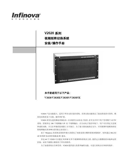
英飞拓矩阵V2020中文说明书
标志提醒用户严格按照本手册的说明和指示进行安装和操作。
警告:为避免火灾及电击的危险,请勿将本产品放置于雨淋或潮湿的地方!
目录
第一章 一般描述 ........................................................................... 1 1.1 特性 ..................................................................................... 1 1.2 描述 ..................................................................................... 1 1.3 关键术语 ............................................................................. 2 1.4 型号 ..................................................................................... 3 1.5 系统附件 ............................................................................. 4
请仔细阅读本手册,并妥善保存好本手册,以便将来查阅。
安全建议与警告
所有电子设备应避免受潮,远离火源或强磁场。 擦拭设备表面时,请使用干燥、柔软的抹布。 请保持设备周围良好的通风环境。 设备长时间不用时,请断开电源。 请使用厂家建议的原配件。 电源及电线应安装在远离地面和入口处的地方。 设备的维护需由专业人员进行。 建议妥善保管包装箱,方便设备的转移或搬运。
VGA矩阵操作说明书V1.0
Professional Matrix Switcher.在使用本系统前,请详细阅读本说明书,并请保管好该手册。
《专业级 VGA 矩阵切换器用户操作手册》以 VGA1209/1218 系列为例作为使用说明, 并可作为其它型号的 VGA 矩阵切换器用户手册。
本手册只作为用户操作指示,不作为维修服务用途。
其所述功能截止日期为 2013 年 5 月,该日期之后因 VGA 矩阵切换器版本不断更新,VGA 矩阵切换器 的实际使用可能会与本手册的内容有出入,这种情况将不属错漏,将根据实际情 况另作书面说明。
目 录一、前面板按键及遥控器说明及操作方法 (3)二、通讯协议及控制指令代码 (9)三、控制软件使用 (11)一、 前面板按键及遥控器说明及操作方法 前面板图示:按遥控器控制操作方法如下图:操作界面显示(前面板LCD屏):待机画面, 在任何状态下按“Cancel”返回此画面:菜单说明,按 S witch 键进入切换菜单,多次按此键,在以下功能间切换:Switch 各界面功能及操作:一对一单通道切换界面在箭头前输入想要切换通道的输入端口, 箭头后输入输出端口, 输入两位数会自动执行或按”OK”键执行.N 对N 多通道切换界面按”OK”键执行N 对N 多通道切换, 依次将输入通道1切换到输出通道1, 输入通道2切换到输出通道2,….输入通道N 切换到输出通道N. 如输入输出通道数目非一一对应, 则多余输入或输出通道关闭.一对N 多通道切换界面在箭头前输入想要切换的输入通道,将此通道输出到所有输出通道.巡检功能界面如图所示依次输入巡检功能各参数,通过巡检开关参数打开或关闭巡检功能,可通过上或下键在各参数编辑区域跳转,巡检功能在退出此界面后依然有效,如需改变巡检功能请再次进入此界面设置.菜单说明,按Fun 键进入功能菜单,多次按此键,在以下功能间切换:STATUS RECALLFun 各界面功能及操作状态保存界面输入要保存的组数,将当前通道对应关系保存到对应数据组里,可以保存从1到20共20组数据状态恢复界面输入要恢复的组数,将对应数据组的通道对应关系恢复到当前状态蜂鸣器开关界面按”OK”键打开或关闭蜂鸣器,蜂鸣器打开后按键或遥控器操作会有蜂鸣声.系统状态界面此界面无操作,仅供显示系统信息.二、通讯协议及控制指令代码本指令系统用于ASCII模式的串口通讯软件进行控制和操作。
数字矩阵(简要操作说明)

数字矩阵/网络视频解码矩阵使用说明书 扫码查看数字矩阵简要操作说明 (IE 操作)系统连接示意图数字视频墙Digital V ideoWallIP C amera 网络摄像机I P Camer a 网络摄像机NE TWORKN e twork Vi de o R e cod e r 网络视频服务器D i gi ta l Vi de o R e cod e r 硬盘录像机N e t w o r k V id e o D e c o d e r M a t r ix 网络数字矩阵 Key board 控制键盘(V 20以上) P C 计算机NO TEB O OK 计算机设备连接:数字矩阵的网络口与交换机连接,注:后背板上所有“LAN ”的网络口都需要接上网线。
矩阵HDMI 输出口与大屏的HDMI 接口相连接。
操作步骤:1、设备出厂时,默认IP 地址为192.168.0.200,默认子网掩码:255.255.255.0,默认用户名:admin ,默认密码:admin 。
2、需要将主控计算机IP 地址设置为和数字矩阵同一个网段,如192.168.0.XXX.3、直接打开浏览器,在地址栏输入192.168.0.200敲回车键,进入矩阵登陆界面,输入用户名密码登陆,建议使用谷歌浏览器。
4、初始化窗口:进入主界面点输出管理,点初始化窗口,可根据现场大屏布局排列来初始化窗口,如现场大屏是行3列4,则初始化时也选择行3列4,分辨率一般选择1080P ,制式可选P 制或N 制。
5、添加信号源:进入主界面点“输入源管理”来添加信号源,此时注意查看输入源IP 段是否与矩阵同一网段,如网段相同,直接点“搜索”,即可自动搜索出同网段所有信号源。
点击全选,批量输入用账号密码,此时输入的是信号源的用户名和密码,点确定,再点添加,再点“同步管理”里的上传数据。
6、如网段不相同,则需要修改矩阵的IP 或添加网段,进入主界面点“系统管理”里的系统设置,在左侧点网络设置,弹出IP 地址窗口,点添加IP 地址,输入与信号源相同的网段地址后,点确定再点设置,然后重复第6步骤。
HDMI8808矩阵说明书V10

2 SWT 3 END
(2)、AND键:即与操作,在LCD上显示'&'字符,当一个输入 端口同时切换到 多个输出端口时,使用这个命令可以快速实现切换操作。 命令格式:输入端 口号 S WT 输出端口号 A ND 输出端口 号…AND 输出端 口 号 END 举例说明:第二路输入端口切换到第三路、第四路和第八路输出端口,应 执行以下按键操作:
图 3 搜索 2000 操作 如果此 时H D M 88 08主机已 接通电 源并且L A N网线已 连接好,将会搜索到当前局域 网内 所有的C2 0 0 0网络 设备,选 择一个 未被系统 使用的 串口,如 图4所 示:
T568B 接线顺序
引脚序号 1 2 3 4 5 6 7 8
网线颜色 橙白 橙 绿白 蓝 蓝白 绿 棕白 棕
6.2 L A N通信软件安装及使用
-7-
HDMI矩阵(HDM-8808)使用说明书 在使用L AN接口前,先安装C 2 0 0 0软件包(这个软件可 向我可以申请),安装过程采
用默 认方式即可。安 装完成后 ,在开 始菜单可 以找到如下安装 好的程序,如图2所示 。
-4-
HDMI矩阵(HDM-8808使用说明书
STO 3
( 5)、R C L键: 全称R ecal l即调用键,可以将保 存在F 0~F 9存储区中对应关系直接 调 用出来使用,省去重新设置的麻烦。 命令格式:RCL存储区(F0~F 9 ) 举例说明:调用存储 区F3的 路由 关系 ,应执行 以下按 键操作:
3.2 H D M I矩阵背面
序号 1 2 3 4 5 6 7
SIGLENT SSM5000A系列集成开关矩阵操作指南说明书

QS10050_E01AQuickStartSIGLENT TECHNOLOGIES CO., LTDContents1.Copyright and statement (2)2.General safety summary (2)3.General inspection (3)4.Preparing for use (3)5.Front panel (5)6.Rear panel (7)er interface (8)8.Firmware operation (10)9.Help information (11)10.Remote control (11)11.Product certification (11)12.For more product information (11)1. Copyright and statement◆SIGLENT TECHNOLOGIES CO., LTD All Rights Reserved.◆SIGLENT is the registered trademark of SIGLENT TECHNOLOGIES CO., LTD.◆SIGLENT products are protected by patent law worldwide.◆Information in this publication replaces all previously corresponding material.◆SIGLENT reserves the right to modify or change parts of or all the specifications or pricingpolicies at the company’s sole decision.◆Any method of copying, extracting or translating the contents of this manual is not allowedwithout the permission of SIGLENT.2. General safety summaryCarefully read the following safety precautions to avoid any personal injury or damage to the instrument and any products connected to it. To avoid potential hazards, please use the instrument as specified:◆Only qualified technicians can carry out maintenance of the product.◆Only the power cord designed for the instrument and authorized by the local country couldbe used.◆The instrument is grounded through the protective earth conductor of the power cord. Toavoid electric shock, please make sure the instrument is grounded correctly before connecting its input or output terminals.◆The potential of the signal wire ground is equal to the earth, so do not connect the signalwire to a high voltage.◆To avoid fire or electric shock, please look over all ratings and safety labels on theinstrument. Before connecting the instrument, please read the manual carefully to gain more information about the ratings.◆Do not touch exposed contacts or components when the power is on.◆To avoid short-circuiting to the interior of the device or electric shock, please do not operatethe instrument in a humid environment.◆To avoid damage to the device or personal injury, it is important to operate the device awayfrom an explosive atmosphere.◆To avoid the influence of dust and moisture in the air, please keep the surface of the deviceclean and dry.Safety terms and symbols:◆Terms on the product, these terms may appear on the product.DANGER:Indicates direct injuries or hazards that may happen.WARNING:Indicates potential injuries or hazards that may happen.CAUTION:Indicates potential damages to the instrument or other property that may happen.◆Symbols on the product, these symbols may appear on the product:Hazardous Voltage Warning Protective Ground Earth Chassis Ground3. General inspectionInspect the shipping container:◆Keep the shipping container or cushioning material until the contents of the shipmenthave been completely checked and the instrument has passed both electrical and mechanical tests. The consigner or carrier will be responsible for damages to the instrument resulting from shipment. SIGLENT will not provide free maintenance or replacementInspect the instrument:◆If the instrument is found to be damaged, defective, or fails in electrical or mechanicaltests, please contact SIGLENT.Check the accessories:◆Please check the accessories according to the packing list. If the accessories areincomplete or damaged, please contact your SIGLENT sales representative.4. Preparing for use◆Dimensions:Figure 4-1 Front View (unit: mm)Figure 4-2 Top View (unit: mm)Adjust the supporting legs:For benchtop operation, you may want to use the supporting legs. Adjust the supporting feet appropriately to tilt the equipment upwards.Figure 4-3 adjusting of supporting legsConnect to AC power supply:The equipment accepts 100-240 V, 50/60/400Hz AC power supply. Please use the power cord provided in the accessory to connect the instrument to the power source5. Front panelFigure 5-1 Front panelPower switch:◆Light-off indicates that the instrument is in the stand-by state. Pressing this button willcause the instrument to begin the start-up process and the power switch light will turn white.◆ A White light constantly on indicates the instrument is in the operating state. A short presswill cause the instrument to save the current settings and then return to the stand-by state and the light will turn Off.RF connectors:Figure 5-2 Front panel RF connectors◆There are two groups of RF connectors. A-D are the source group, 1-24 are the extendedgroup. A and B could be connected to one of 1-6 or 13-18 ports, but A and B can’t be connected to the same number port simultaneously. Such as C and D ports, the number of ports can be connected to are 7-12 and 19-24.◆When a couple of RF connector are linked together, the corresponding port lights abovethe RF connectors will be lit up with the same color.◆To avoid damage to the instrument, the RF connector input signal must meet the following:The DC voltage and the maximum continuous RF power cannot exceed 35V and 20 dBm respectively.6. Rear panelFigure 6-1 Rear panel7. User interfaceSet the link config of ports. Four steps to config:1. Rotatethe knob to select one of the four ports(A-D); 2. push theknobchange the number of linked port;4. push the knob to finishsetting and return.8. Firmware operationCheck system informationEnter the System sub-menu to check the system information, including:◆Startup times◆Vendor◆Product model◆Serial number◆Software version◆Mainboard temperatureFirmware upgradeFollow this procedure to update the instrument firmware1. Download the firmware package from official SIGLENT websites only.2. Extract and copy the .ADS file into the root directory of a USB stick.update the system software.4. The progress bar will appear on the screen while updating, the instrument will restartautomatically if updates succeed or display a pop-up prompt box if updates fail.Note: Please ensure that line power is constant during the upgrade by using an Uninterruptible Power Supply (UPS), Failure to maintain line power may be cause upgrade failure or instrument damage.9. Help informationConnect our sales rep for more information and help.10. Remote controlThe switch matrix supports communication with compatible computers via USB and LAN interfaces. By using these interfaces, in combination with programming languages and/ or NI-VISA software, users can remotely control the switch matrix.11. Product certificationSIGLENT guarantees this product conforms to the national and industrial standards in China as well as the ISO9001: 2008 standard and the ISO14001: 2004 standard. Other international standard conformance certification is in progress.12. For more product informationYou can obtain the instrument information and installation status of all options through Utility menu, for more information of this product, please refer to the following manuals (you can also download them from the SIGLENT web site):◆SSM5000A Switch Matrix user manual:Provides detailed introductions of the functions of this instrument.◆SSM5000A Switch Matrix programming manual:Provides detailed introductions of the SCPI commands and programming of thisinstrument.◆SSM5000A Switch Matrix Data Sheet:Provides the main characteristics and specifications of this instrument.。
矩阵切换器使用说明书
矩阵切换器
Professional Matrix
前言
感谢您使用本公司矩阵切换器,使用时请注意以下事项:
1.本产品所使用电源必须有电源保护地线,输入、输出设备的电源保护地 线要为同一保护地线。确保设备的输入电源为 AC 100~240V/50Hz。
2.使用计算机控制本产品时必须保证控制计算机与本产品的连接电源保护 地线是同一个地线。
1
矩阵切换器
目录
Professional Matrix
前 言....................................................................................................................... 1 目 录....................................................................................................................... 2 一、清单、外形及安装说明 ................................................................................... 4
7
矩阵切换器
矩阵控制操作使用说明书

矩阵操作使用说明书矩阵控制操作使用说明书深圳达实智能股份有限公司2010-8目录一、键盘对视频的选择 (3)二、快球预置位的设置与调用 (3)1、快球预置位的设置: (3)2、快球预置位的调用: (3)三、矩阵的编程和调用 (3)1、系统巡视功能 (4)2、成组切换功能 (5)一、键盘对视频的选择键盘对矩阵控制必须基于监视器的调用,所有功能都必须由键盘先调用一个监视器进行控制,然后再把系统中的某个摄像机的信号切换到该监视器上。
一旦摄像机被调用到监视器上,就可以控制该摄像机上所有的功能,如是快球就可以使用键盘控制快球转动、摄像机对焦、缩放、光圈开关等。
当去控制某个快球时,监视器上出现IN USE并且键盘发出长鸣时说明有别的用户正在控制,当在控制的键盘停止对该快球的控制后,才能对快球进行控制。
摄像机的调用:1)输入需要调用的监视器编号;2)按CLEAR键可以清除键盘上输入的信息;3)按MON键调用该监视器;4)输入需要调用的摄像机编号;5)按CAM键调用该摄像机;数字键数字键二、快球预置位的设置与调用1、快球预置位的设置:选择摄像机,调整好图像,输入自已定义的预置位编号,按【SHOT】键,按住智能键不松,再按【ON】键,最后松开智能键。
调整好图像,进行下一个预置位设置。
2、快球预置位的调用:在数字区输入想要调看的预置图像号码,按【SHOT】键,再按【ACK】键。
如事先没设置该预置图像,监视器图像则无变化。
三、矩阵的编程和调用1、系统巡视功能系统巡视功能是可以通过编程使一系列的画面显示及预置位的调用,或进行成组切换。
通过设定停留时间,可以精确定义每项操作在监视器上显示的时间。
系统巡视的使用:1. 选择想要设置为自由切换的监视器号;2. 输入想要每一摄像机停留的时间(2~240秒);3. 输入自由切换的起始摄像机号;4. 输入自由切换的结束摄像机号。
例如:在3号监视器上切换1-6号摄像机,画面停留2秒:1. 按【 3 】键,再按【MON】键(选择监视器);2. 按【 2 】键(输入自由切换停留时间);3. 稍长时间按住【RUN】键,直到显示屏显示“TIM”时松开键;4. 按【 1 】键,再按【ON】键(起始摄像机号);5. 按【 6 】键,再按【OFF】键(结束摄像机号)。
至龙五输入大屏矩阵开关操作指南说明书
Atlona Manuals SwitchersA T -UHD-SW-510WSolution Setup and Configuration GuideFive-Input Universal Matrix Switcherwith Wireless Presentation Link4K/UHDVersion InformationTable of ContentsIntroduction 4 Solution Setup and Configuration Guide 5Input Auto Switching 5 Display Control 7 CEC Control 7RS-232 Control 11Configuring IP Control 17Scheduling Display Operation Times 19 Trigger Port 20 Wiring 20Configuration using the Web GUI 20 Relay Port 22 Wiring 22Operation 22Configuration using the Web GUI 23IntroductionWelcome to the AT-UHD-SW-510W Solution Setup and Configuration Guide. This document covers the following topics:• Input Auto SwitchingThis section explains how to configure the AT-UHD-SW-510W to automatically switch inputs, when sources are connected or disconnected.• Display ControlThe AT-UHD-SW-510W provides control of display (sink) devices through CEC, RS-232, or IP protocols.Step-by-step instructions are provided on how to setup each protocol and how to enter commands.In addition, the display can be automatically powered-on or powered-off based on the current time and date.The “Scheduling Display Times” section will cover this procedure.• Trigger Port and Relay PortEach of these sections explain how to connect devices such as occupancy sensors, screens, curtains, and how to configure the AT-UHD-SW-510W to work with these devices.Auto-switching is enabled (On), by default, and can be enabled or disabled through the web GUI.1. Launch a web browser.2. In the address bar, type the IP address of the AT-UHD-SW-510W.3. Enter the login credentials and click the Login button. The default credentials are listed below:Username: admin Password: Atlona 4. The Info page will be displayed, as shown on the next page.5. Click Display in the menu on the left side of the window.6. Locate the AutoSwitch check box, under the Control window group.7. Click this check box to enable auto-switching. When auto-switch is enabled, a check mark will appear in thisbox. To disable auto-switching, click the AutoSwitch check box again.Display ControlThe following section cover display control using the following methods:• CEC • RS-232•IPCEC ControlCEC Control over HDMIConsumer Electronics Control (CEC) is the simplest method when working with a consumer display. Note that the display must have CEC enabled to receive CEC messages. CEC can be transmitted over HDMI and/or HDBaseT. Note that if both connection methods are used, simultaneously, the same CEC messages will be transmitted over both HDMI OUT and HDBaseT OUT ports.a. Connect an HDMI cable from the HDMI OUT port on the AT-UHD-SW-510W to an HDMI input on the displaydevice.CEC Control over HDBaseT1. Enable CEC on the display device. Refer to the documentation for the display device. It should be noted thatdifferent manufacturers will identify CEC with their own brand name. Refer to the table below.a. Connect a category cable (CAT-5e or better) from the HDBaseT OUT port on the AT-UHD-SW-510W to acompatible receiver. The example below uses an AT-UHD-100CE-RX-PSE.b. Connect an HDMI cable from the HDMI OUT port on the receiver to the HDMI input on the display device.NOTE: If using AMS and the AT-UHD-SW-510W is running 2.4.0 or greater, click on the device withinAMS to access the web interface.4. The Login page will be displayed. Enter the required credentials. The default credentials are shown below:Username: adminPassword: Atlona5. Click the Submit button or press the ENTER key on the keyboard.6. Click Display in the menu on the left side of the window.7. Click the Control Type drop-down list and select CEC.8. Under the CEC section, next to HDMI, test the power-on and power-off commands by clicking the ON and OFFbuttons, respectively. The display should power-on and power-off when clicking these buttons.Solution Setup and Configuration Guide If the display does not respond, check the following:• Verify that CEC is enabled on the display device.• Verify the integrity of the HDMI cable. Try connecting a different HDMI cable between the AT-UHD-SW-510W and the display device.• Try connecting the HDMI cable to a different HDMI input on the display device.Consumer Electronics Control (CEC): Atlona has confirmed proper CEC functionality with several current models of Samsung, Panasonic, and Sony displays. However, it is not guaranteed that CEC will work with all displays. Many manufacturers do not support the CEC “off” command, and older displays use proprietary commands. Atlona only supports displays that use the CEC command structure defined in HDMI 1.2a. It is recommended that dealers re-quest an evaluation product from Atlona, before designing a system using the CEC protocol. If this is not possible, then other control methods will need to be considered, in order to control displays using Atlona products.AT-UHD-SW-510WRS-232 ControlD i sp l a yA T -U H D -S W -510WN D TR x DThe AT-UHD-SW-510W can be connected directly to the display, using these ports, or a receiver, such as the AT-UHD-100CE-RX-PSE can be used to extend these signals to a remote display, up to 330 feet (100 meters) away. No external control system is required. This allows for convenient control of the display device from the location of the source device.Two RS-232 connection methods will be covered in this section:• Controlling a Display from the AT-UHD-SW-510W •Controlling a Display over HDBaseT1. port on the AT-UHD-SW-510W to the RS-Controlling a Display from the AT-UHD-SW-510WHDBaseT (up to 330 feet / 100 meters)1.must be AT-UHD-100CE-RX-PSE2. Connect the included 3-pin captive screw connector from the RS-232 port on the AT-UHD-EX-100CE-RX-PSE toAT-UHD-EX-100CE-TX-PSED i sp l a yA T -U HD-E X -100CE -T X -PS EN D T R x DControlling a Display over HDBaseTUsername: admin Password: Atlona 4. Click the Submit button or press the ENTER key on the keyboard.5. Click Display in the menu on the left side of the window.6. Click the Control Type drop-down list and select RS-232.NOTE: If Local RS232 Only or Both is selected, then the AT-UHD-SW-510W cannot be controlled from a controlled system using RS-232.7. Scroll down and locate the RS-232 section.a. If the RS-232 cable is connected directly from the AT-UHD-SW-510W to the display, then click the RS232Mode drop-down list and select Local RS232 Only .b. If the RS-232 cable is connected to a remote extender, over HDBaseT, then click the RS232 Mode drop-down list and select HDBaseT RS232 Only .9. Scroll down to the RS-232/IP Commands section and click the Manufacturer drop-down list to select themanufacturer of the device that is being controlled.10. Continue fine-tuning the device selection by clicking the Products and Model drop-down lists. Once all fieldshave been set to the proper values, the AT-UHD-SW-510W will populate the ON , OFF , Volume+, Volume-, and Mute fields with the commands used by that device.Refer to the next page for example command strings.8. Click the Baud Rate , Data Bits , Parity , and Stop Bits drop-down list to set the values required by the controlsystem. If these values do not match the RS-232 settings of the control system, then RS-232 control will not function properly.NOTE: If the manufacturer/model is not listed in the drop-down lists, then commands for the ON , OFF , Volume+, Volume-, and Mute fields can be entered manually. Consult the User Manual for the sink device to obtain the correct command format.HEX Command StringsASCII Command Stringsa. An example hexadecimal power-on command for a display might be:\xBE\xEF\x03\x06\x00\xBA\xD2\x01\x00\x00\x60\x01\x00\x0DConsult the display documentation for the correct command strings.b. Make sure the command string is terminated correctly. In most cases, a CR (carriage return) should bespecified. In the example above, “\x0D” is the hexadecimal value for a carriage return. a. An example ASCII power-on command for a display might be:PWOFF\x0DNote the use of the “\x0D” delimter in the command string. This must be used to terminate the command string.11. Click the Send button to test each command.12. Click the Savebutton to commit changes.Configuring IP ControlAT-UHD-100CE-RX-PSEDisplay control can also be performed over IP . The steps are similar to the HDBaseT RS-232 setup, except that an Ethernet cable is connected between the LAN port on the extender and the display device.The following example shows how to extend IP control, using the AT-UHD-100CE-RX-PSE.1. HDBaseT IN port onmust be 2. Connect an Ethernet cable from the LAN port on the AT-UHD-EX-100CE-RX-PSE to the Ethernet port on thedisplay device.9. Locate the IP section and enter the IP address, of the device that is being controlled, in the IP address field.10. Enter the port number in the Port field. Valid port numbers can be from 0 to 65535.11. Refer to step 9, on page 13, to complete the configuration process.5. The Login page will be displayed. Enter the required credentials. The default credentials are shown below:Username: admin Password: Atlona 6. Click the Submit button or press the ENTER key on the keyboard.7. Click Display in the menu on the left side of the window.8. Click the Control Type drop-down list and select IP .5. Click drop-down lists, next to Start Time , to set the hour and minute when the display will be powered-on.Time is specified in 24-hour format.6. Click the End Time drop-down lists, for both hour and minute, to specify the display power-off time. Time isspecified in 24-hour format.7. Click the Timezone drop-down list to set the proper time zone.8. Click the desired checkbox(s) to specify which day(s) that the unit will power-on and power-off the connectedDisplay Auto PowerEnable Time Display Control3. Click the Display Auto Power check box. When enabled, a check mark will appear in this box.4. Click the Enable Time Display Control check box.The TRIGGER I/O port, on the rear panel, allows voltage-controlled devices, such as an occupancy sensor, to be connected to the AT-UHD-SW-510W. Use the included 4-pin captive screw connector to connect the device. The trigger voltage range is 3 V to 30 V DC.Configuration of the TRIGGER I/O port can be done through the web GUI or using API commands. Refer to the Application Programmers Interface, on the Atlona AT-UHD-SW-510W product web page, for more information.Passive sensorPowered sensorIMPORTANT: Some occupancy sensors require 24 V DC instead of 12 V DC. In these cases, an external power supply will be required in order to power the sensor.1. Launch a web browser.2. In the address bar, type the IP address of the AT-UHD-SW-510W.Trigger PortWiringConfiguration using the Web GUINOTE: If using AMS and the AT-UHD-SW-510W is running 2.4.0 or greater, click on the device within AMS to access the web interface.3. The Login page will be displayed. Enter the required credentials. The default credentials are shown below:Username: admin Password: Atlona4. Click the Submit button or press the ENTER key on the keyboard.5. Click Display in the menu on the left side of the window.6. Locate the Trigger I/O section.7. Click the desired checkboxes for the desired operation. By default, both Enable Power Off and Enable Power On are checked (enabled).22Relay PortThe AT-UHD-SW-510W provides a RELAY port, which provides a control interface for screens, curtains, and or other devices.The RELAY connector is wired to a pair of single-pole single-throw (SPST) relays, as shown below, providing two independent switches and a common (COM) connection. The relay is designed to work with devices that conform to standard Low Voltage Control (LVC). The AT-UHD-SW-510W software allows only a single relay switch to be enabled at any time.The AT-UHD-SW-510W can be programmed through the built-in web GUI to pulse the C2 contact when the AT-UHD-SW-510W is active and then pulse the C1 contact when the AT-UHD-SW-510W becomes inactive. Pulse length can also be configured using the web GUI. Refer to the next page for more information.IMPORTANT: The maximum voltage and current for the RELAY connector is 48 V / 1 A DC.IMPORTANT: When the AT-UHD-SW-510W is powered-on or rebooted, both C1 and C2 are will be in the Normally Open (NO) state.WiringOperationConfiguration of the RELAY port can be done through the web GUI or using API commands. Refer to the Application Programmers Interface, on the Atlona AT-UHD-SW-510W product web page, for more information.1. Launch a web browser.2. In the address bar, type the IP address of the AT-UHD-SW-510W.Configuration using the Web GUINOTE: If using AMS and the AT-UHD-SW-510W is running 2.4.0 or greater, click on the device withinAMS to access the web interface.3. The Login page will be displayed. Enter the required credentials. The default credentials are shown below:Username: adminPassword: Atlona4. Click the Submit button or press the ENTER key on the keyboard.5. Click Display in the menu on the left side of the window.6. Locate the Relay section.7. Click the Enable Momentary Relay check box to enable relay operation.8. Click the Relay Pulse Duration drop-down list and select the desired duration. Note that some external devicesmay not recognize pulse durations less than 1 second. In this case, it may be necessary to select a larger time interval.T oll free US International • 877.536.3976 • 41.43.508.4321© 2019 Atlona Inc. All rights reserved. “Atlona” and the Atlona logo are registered trademarks of Atlona Inc. All other brand names and trademarks or registered trademarks are the property of their respective owners. Pricing, specifications and availability subject to change without notice. Actual products, product images, and online product images may vary from images shown here.。
- 1、下载文档前请自行甄别文档内容的完整性,平台不提供额外的编辑、内容补充、找答案等附加服务。
- 2、"仅部分预览"的文档,不可在线预览部分如存在完整性等问题,可反馈申请退款(可完整预览的文档不适用该条件!)。
- 3、如文档侵犯您的权益,请联系客服反馈,我们会尽快为您处理(人工客服工作时间:9:00-18:30)。
一、高清混合矩阵切换器(HDMI)
原理
矩阵的接口分为信号输入\输出接口,INPUT 部分为信号输入端,OUTPUT部分为信号输出端。
将信号源(如电脑、DVD机)设备的输出端接入矩阵输入端(INPUT),将矩阵输出端(OUTPUT)接至信号使用设备(如投影机、电视机)的输入接口。
主要按键
1、Cancel键(取消键)在任何页面按“Cancel”都会回到待机画面状态。
2、ENTER键(确认键)相当于电脑的回车键,表示进入、确认
3、VIDEO键(视频键)视频切换模式按钮
4、AUDIO键(音频键)音频切换模式按钮
5、AV键(音视频键)音视频同步切换模式按钮
6、ALL:所有按钮,输入端口对所有输出端口时使用
7、SWITCH切换键按Switch 键进入切换菜单,多次按此键,可以在VIDEO、AUDIO、AV模式切换。
7.1 AV SWITCH,音视频同时切换。
在这个状态下,用数字键输入输入通道号和输出通道号,然后按OK(Enter)键,实现切换
7.2 VIDEO SWITCH,只切换视频,而不切换音频
7.3 AUDIO SWITCH,只切换音频,而不切换视频
7.4 AV TO ALL,把某路输入音视频同时切换到所有输出
7.5 AV N TO N,进行一对一切换,1到1,2到2,3到3,······n 到n
其它按键(选择了解)
POWER:电源指示灯RUN:矩阵工作指示灯IR:红外遥控接收头窗口SAVE:模式保存按钮MODE:模式调用按钮ALL:所有按钮,输入端口对所有输出端口时使用F1:自定义键(默认一一对应)FUN键(功能键):进入功能菜单,多次按此键可以在对应功能间切换。
操作步骤
1、通过HDMI接口,将笔记本(信号源)与一号桌插相连。
注:一号桌插对应HDMI矩阵的一号输入口。
2、在矩阵待机状态下两次按SWITCH切换键,出现以下界面:
3、在问号处键入数字1,因为步骤1中选择的是1号桌插。
4、按ENTER键确定操作,矩阵回到待机状态,成功完成音视频切换。
注:(1)从主席台到大屏幕方向依次对应着桌插的1、2、3···6顺序。
(2)如果使用2、3···6号桌插在步骤3中请键入对应的2、3···6号数字。
(3)在使用机柜旁边预留的HDMI接口时,步骤3中键入数字7。
(因为此输入口对应着矩阵的7号输入口)
二、VGA矩阵切换器
原理、使用方法还有操作步骤和HDMI矩阵大致相似,但在设置好VGA矩阵后还需要设置HDMI矩阵,才能完成信号的正常传输。
具体操作步骤如下:
1、通过VGA 接口,将笔记本(信号源)与一号桌插相连。
2、在VGA矩阵待机状态下按AV键,出现如右下界面:
3、键入数字1。
(现在选择的是1号桌插)
4、输入按键ALL
5、按ENTER键确认,矩阵回到待机状态,完成对VGA矩阵的操作。
接下来还要继续对HDMI矩阵进行设置。
6、在HDMI矩阵待机状态下两次按SWITCH切换键,出现以下界面:
7、在问号处键入数字8。
(VGA矩阵的所有输出信号都会作为输入信号从HDMI矩阵的8号口输入)
8、按ENTER键确定,这样就完成所有操作。
注:在使用VGA矩阵时,如果传输的信号源包含声音,如视频、宣传片、电影时,在步骤一中还需要插入音频线,才能将音视频完整传输过来,如下图。