IXGH120N30C3;中文规格书,Datasheet资料
富士通 PRIMERGY TX1320 M3塔式服务器 数据手册说明书
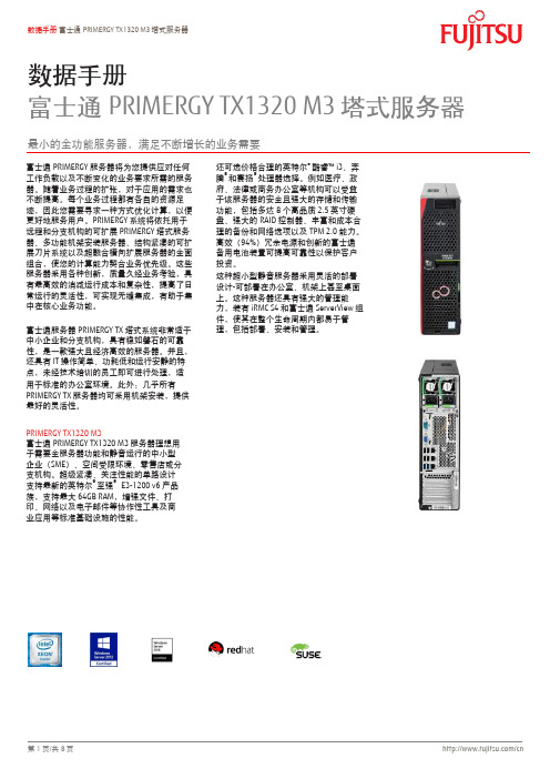
数据手册富士通PRIMERGY TX1320 M3塔式服务器最小的全功能服务器,满足不断增长的业务需要富士通PRIMERGY服务器将为您提供应对仸何工作负载以及不断变化的业务要求所需的服务器。
随着业务过程的扩张,对于应用的需求也不断提高。
每个业务过程都有各自的资源足迹,因此您需要寻求一种斱式优化计算,以便更好地服务用户。
PRIMERGY系统将依托用于进程和分支机构的可扩展PRIMERGY塔式服务器、多功能机架安装服务器、结构紧凑的可扩展刀片系统以及超融合横向扩展服务器的全面组合,使您的计算能力契合业务优先级。
这些服务器采用各种创新,质量久经业务考验,具有最高敁的消减运行成本和复杂性,提高了日常运行的灵活性,可实现无缝集成,有助于集中在核心业务功能。
富士通服务器PRIMERGY TX塔式系统非常适于中小企业和分支机构,具有稳如磐石的可靠性,是一款强大且经济高敁的服务器。
幵且,还具有IT操作简单、功耗低和运行安静的特点,未经技术培训的员工即可迚行处理,适用于标准的办公室环境。
此外:几乎所有PRIMERGY TX服务器均可采用机架安装,提供最好的灵活性。
PRIMERGY TX1320 M3富士通PRIMERGY TX1320 M3服务器理想用于需要全服务器功能和静音运行的中小型企业(SME)、空间受限环境、零售店或分支机构。
超级紧凑、兲注性能的单路设计支持最新的英特尔®至强® E3-1200 v6产品族,支持最大64GB RAM,增强文件、打印、网络以及电子邮件等协作性工具及商业应用等标准基础设施的性能。
还可选价栺合理的英特尔®酷睿™ i3、奔腾®和赛扬®处理器选择。
例如医疗、政府、法律或商务办公室等机构可以受益于该服务器的安全且强大的存储和传输功能,包括多达8个高品质2.5英寸硬盘、强大的RAID控制器、丰富和成本合理的备仹和网络选项以及TPM 2.0能力。
MBRS140T3G;中文规格书,Datasheet资料

(Note: Microdot may be in either location)
Lead and Mounting Surface Temperature for Soldering Purposes:
ORDERING INFORMATION
Device MBRS140T3G SBRS8140T3G Package SMB (Pb−Free) SMB (Pb−Free) Shipping† 2,500 / Tape & Reel 2,500 / Tape & Reel
†For information on tape and reel specifications, including part orientation and tape sizes, please refer to our Tape and Reel Packaging Specifications Brochure, BRD8011/D.
DC
3 10
0
1
2
3
4
5
IF(AV), AVERAGE FORWARD CURRENT (AMPS)
Figure 5. Power Dissipation
3
/
MBRS140T3G, SBRS8140T3G
PACKAGE DIMENSIONS
Figure 3. Typical Capacitance
I F(AV) , AVERAGE FORWARD CURRENT (AMPS)
10 9 8 7 6 5 4 3 2 1 0 30 40 50 60 70 80 90 100 TC, CASE TEMPERATURE (C) 110 120 130
DPG60C300HB;中文规格书,Datasheet资料
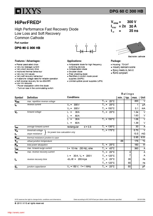
HiPerFRED²Features / Advantages:Applications:Package:Part numberV I RRM ==30030DPG 60 C 300 HBV A 2x Backside: cathodet rr =35nsHigh Performance Fast Recovery Diode Low Loss and Soft Recovery Common Cathode● Planar passivated chips● Very low leakage current ● Very short recovery time ● Improved thermal behaviour ● Very low Irm-values● Very soft recovery behaviour● Avalanche voltage rated for reliable operation ● Soft reverse recovery for low EMI/RFI ● Low Irm reduces:- Power dissipation within the diode- Turn-on loss in the commutating switch● Antiparallel diode for high frequency switching devices ● Antisaturation diode ● Snubber diode● Free wheeling diode● Rectifiers in switch mode power supplies (SMPS)● Uninterruptible power supplies (UPS)FAVI RMS A per pin 50R thCH K/W 0.25M D Nm 1.2mounting torque 0.8T stg °C 150storage temperature-55Weight g 6Symbol DefinitionRatingstyp.max.min.Conditions RMS currentthermal resistance case to heatsink Unit I is typically limited by: 1. pin-to-chip resistance; or by 2. current capability of the chip.In case of 1, a common cathode/anode configuration and a non-isolated backside, the whole current capability can be used by connecting the backside.F CN120mounting force with clip20Ordering Delivering ModeBase Qty Code KeyStandard Part Name DPG 60 C 300 HB 502163Tube 30D P G 60C 300 HBPart numberDiodeHiPerFRED extreme fastCommon CathodeT O-247AD (3) ===DPG60C300QB DPG60C300HJ DPG60C300PC DPF60C300HB TO-3P (3)ISOPLUS247 (3)TO-263AB (D2Pak) TO-247AD (3)Similar PartPackage1)1)Marking on Product DPG60C300HB 300300300300Voltage ClassCurrent Rating [A]Reverse Voltage [V]====RMSDPG80C300HB TO-247AD (3)300分销商库存信息: IXYSDPG60C300HB。
H13003
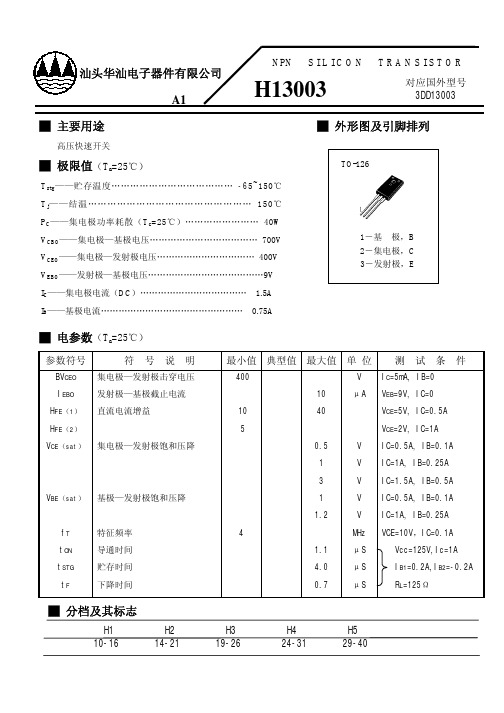
█ 外形图及引脚排列
TO-126
1―基 极,B 2―集电极,C 3―发射极,ELeabharlann █ 电参数(Ta=25℃)
参数符号
符号说明
BVCEO 集电极—发射极击穿电压
IEBO
发射极—基极截止电流
HFE(1) HFE(2)
直流电流增益
VCE(sat) 集电极—发射极饱和压降
VBE(sat) 基极—发射极饱和压降
fT
特征频率
tON
导通时间
tSTG
贮存时间
tF
下降时间
最小值 典型值 最大值 单 位 测 试 条 件
400
V IC=5mA, IB=0
10
μA VEB=9V, IC=0
10
40
VCE=5V, IC=0.5A
5
VCE=2V, IC=1A
0.5
V IC=0.5A, IB=0.1A
1
V IC=1A, IB=0.25A
3
V IC=1.5A, IB=0.5A
1
V IC=0.5A, IB=0.1A
1.2
V IC=1A, IB=0.25A
4
MHz VCE=10V,IC=0.1A
1.1
μS
Vcc=125V,Ic=1A
4.0
μS
IB1=0.2A,IB2=-0.2A
0.7
μS
RL=125Ω
█ 分档及其标志
H1 10-16
H2 14-21
H3 19-26
H4 24-31
H5 29-40
汕头华汕电子器件有限公司 A1
NPN S I L I C O N
H13003
TRANSISTOR
Lenovo ThinkAgile HX 系列产品说明说明书

ThinkAgile HX Certified Nodes Rapidly and confidently deploy HCI clustersOptimize Your HCI DeploymentWhen it comes to hyperconverged deployments, Lenovo offers flexibility so that customers can choose the model that best suits their business needs.Since 2014, Lenovo has collaborated with Nutanix to offer ThinkAgile HX Series, a best-in-class turnkey hyperconverged system that integrates, validates, and optimizes Nutanix’s industry-leading software with Lenovo's highly reliable platforms — including white-glove Lenovo deployment services.ThinkAgile HX appliances include a bundled Life of Device license, which remains with the appliance for its lifetime. For customers who prefer to provide their own Nutanix software licenses, Lenovo offers another choice: the ThinkAgile HX Certified Node, which includes:Fully validated configured and integrated hardware and firmware, certified with Nutanix softwarePreloaded Nutanix software for ready deployment, Nutanix term license obtained separatelyFlexibility to bring your own Nutanix term-basedlicense, transferable to other HX certified nodesFlexibility to provide your own deployment services or optionally use Lenovo Deployment Services Increase Simplicity and UptimeThinkAgile HX consolidates compute, storage, and virtualization software into simple building blocks, easily managed in scale-out clusters through a single interface. Achieve even simpler IT operations by using Nutanix Prism for one-click provisioning, insights, and firmware updates. Lenovo XClarity, a fast and intuitive resource management tool, can be used in concert with Prism.A successful hyperconverged deployment depends on reliable servers that ensure your business-critical workloads run without interruption. For 9 years running, Lenovo servers have ranked as the industry’s most reliable x86 platforms. Enhanced with faster processors and memory, Lenovo platforms hold more than 294 current performance world records, so you can run your workloads with blazing-fast speed. New refreshed HX series featuring the latest technological advancements in processing with 4th generation processors from Intel and AMD is now available with more cores and greater GPU density.With ThinkAgile HX Certified Nodes, you have the freedom to bring your own Nutanix term-based licenses while leveraging outstanding Lenovo reliability and performance plus Nutanix simplicity. Deploy yourHCI clusters rapidly and confidently with Lenovo.ThinkAgile HX 1U Eaglestream Certified Nodes - IntelThe 1U 1-node ThinkAgile HX 1U Eaglestream Certified Nodes is engineered for light-to-compute heavy workloads like business applications, VDI, optimized for remote office/branch office (ROBO) environments & databases. SpecificationsModel HX630 V3 ROBO Certified Nodes, 1U form factor HX630 V3 Certified Nodes, 1U form factor Target Audience Remote Office/Branch Office (ROBO)Small and Medium BusinessesProcessor1-2x 4th Generation Intel® Xeon® Silver, Gold, orPlatinum processor, up to 350W 2x 4th Generation Intel® Xeon® Silver, Gold, or Platinum processor, up to 350WMemory64GB - 4TB64GB - 8TBDrive Bays4x 3.5" + 2x 2.5” (Optional)10x 2.5" + 2x 2.5” (Optional)Hybrid Configuration SSD: 2x 1.6 TB, 1.92TB, 3.84TB, 7.68TBHDD: 2-4x 4TB, 6TB, 8TB, 10TB, 12TB, 16TB, 20TBNot applicableAll-Flash Configuration SAS/SATA: 2-4x 1.6TB, 1.92TB, 3.84TB, 7.68TB SAS/SATA: 2-12x 1.6TB, 1.92TB, 3.84TB, 7.68TBNVMe: 1.6TB, 1.92TB, 3.2TB, 3.84TB, 6.4TB, 7.68TB 10GBASE-T2-42-825GbE SFP28 Ports2-42-8Hypervisors Supported Nutanix Acropolis Hypervisor (preloaded), VMware ESXi (optional preload)Systems Management Hardware management via Lenovo XClaritySoftware management through Nutanix PrismFirmware upgrade via Nutanix Life Cycle Manager (LCM)License Options Nutanix New Pricing & Packaging; (PnP)Deployment Services Lenovo Professional Deployment services availableWarranty Support Lenovo 3-year, 4-year, or 5-year limited hardware warrantyThinkAgile HX 2U Eaglestream Certified Nodes - IntelThe 2U 1-node ThinkAgile HX 2U Eaglestream Certified Nodes is engineered for in memory databases, analytics, AI/ML, VDI, mission critical workloads.SpecificationsModel HX650 V3 Storage Certified Nodes, 2U form factor HX650 V3 Certified Nodes, 2U form factor Target Audience Big Data and High Capacity Mission critical workloadsProcessor2x 4th Generation Intel® Xeon® Silver, Gold, orPlatinum processor, up to 350W 2x 4th Generation Intel® Xeon® Silver, Gold, or Platinum processor, up to 350WMemory64GB - 8TB64GB - 8TBDrive Bays12x 3.5"+4x 2.5" (Optional)24x 2.5"Hybrid Configuration SSD: 2-12x 1.6 TB, 1.92TB, 3.84TB, 7.68TBHDD: 4-12x 4TB, 6TB, 8TB, 10TB, 12TB, 16TB, 20TBNot applicableAll-Flash Configuration SAS/SATA: 2-12x 1.6TB, 1.92TB, 3.84TB, 7.68TB SAS/SATA: 4-24x 1.6TB, 1.92TB, 3.84TB, 7.68TBNVMe: 2-8x 1.6TB, 1.92TB, 3.2TB, 3.84TB, 6.4TB,7.68TB10GBASE-T2-122-1225GbE SFP28 Ports2-122-12Hypervisors Supported Nutanix Acropolis Hypervisor (preloaded), VMware ESXi (optional preload)Systems Management Hardware management via Lenovo XClaritySoftware management through Nutanix PrismFirmware upgrade via Nutanix Life Cycle Manager (LCM)License Options Nutanix New Pricing & Packaging (PnP)Deployment Services Lenovo Professional Deployment services availableWarranty Support Lenovo 3-year, 4-year, or 5-year limited hardware warrantyThe 1U 1-node ThinkAgile HX 1U Icelake Certified Nodes is engineered for light-to-compute heavy workloads like business applications, VDI, optimized for remote office/branch office (ROBO) environments & databases.SpecificationsModel HX1331 Certified Nodes, 1U formfactor HX2331 Certified Nodes, 1U formfactorHX3331 Certified Nodes, 1U formfactorTarget Audience Remote Office/Branch Office(ROBO)Small and Medium Businesses General virtualization and VDIProcessor1x 3rd Generation Intel® Xeon®Silver, Gold, or Platinum processor,up to 270W 2x 3rd Generation Intel® Xeon®Silver, Gold, or Platinum processor,up to 270W2x 3rd Generation Intel® Xeon®Silver, Gold, or Platinum processor,up to 250WMemory64GB - 2TB64GB - 4TB64GB - 4TBDrive Bays4x 3.5" + 2x 2.5” (Optional)4x 3.5" + 2x 2.5” (Optional)10x-12x 2.5"SSD Options(Hybrid Config)2x 1.6 TB, 1.92TB, 3.84TB, 7.68TB2x 1.92TB, 3.84TB, 7.68TB2x-4x 1.6TB, 1.92TB, 3.84TB, 7.68TBHDD Options (Hybrid Config)2x or 4x 4TB, 6TB, 8TB, 10TB, 12TB,16TB2x or 4x 4TB, 6TB, 8TB, 10TB, 12TB,16TB4-10x 1TB, 2TB, 2.4TBSSD Options (All-Flash Config)2x, 4x or 6x 1.6TB, 1.92TB, 3.84TB,7.68TB2x, 4x or 6x 1.6TB, 1.92TB, 3.84TB,7.68TB2x-12x 1.6TB, 1.92TB, 3.84TB,7.68TBAll-NVMe Options none none2x,10x, 12x 1.6TB, 3.2TB, 3.84TB,6.4TB,7.68TBGPU0-1x single wide0-2x single wide0-2x single wide10GBASE-T2-62-62-625GbE SFP28 Ports2-42-62-6HypervisorsSupportedNutanix Acropolis Hypervisor (preloaded), VMware ESXi (optional preload)Systems Management Hardware management via Lenovo XClaritySoftware management through Nutanix Prism Firmware upgrade via Nutanix Life Cycle Manager (LCM)License Options Life of device (LOD) licenseDeploymentServicesLenovo Professional Deployment services available Warranty Support Lenovo 3-year, 4-year, or 5-year limited hardware warrantyThe 2U 1-node ThinkAgile HX Certified Nodes are engineered for storage-heavy workloads (Big Data and enterprise applications) and offer a high-capacity model.SpecificationsModel HX5531HX7531 (+ SAP HANA)Workloads Big Data and High Capacity High Performance and DatabasesForm Factor2U2UProcessor2x 3rd Generation Intel® Xeon® Silver, Gold, orPlatinum processor, up to 220W 2x 3rd Generation Intel® Xeon® Silver, Gold, or Platinum processor, up to 270WMemory64GB - 4TB64GB - 4TBDrive Bays12x 3.5" + 4x 2.5” (optional)24x 2.5"SSD Options (HybridConfig)2x-6x, 1.6TB, 1.92TB, 3.84TB, 7.68TB24x-8x 1.6TB, 1.92TB, 3.84TB, 7.68TBHDD Options (HybridConfig)6x-12x 4TB, 6TB 6x-10x 8TB 8x 10TB, 12TB, 16TB8x-20x 1TB, 2TB, 2.4TBSSD Options (All-FlashConfig)2x-16x 1.6TB, 1.92TB, 3.84TB, 7.68TB4x-24x 1.6TB, 1.92TB, 3.84TB, 7.68TBNVMe Options (All-FlashConfig)None0, 2x or 4x 1.6TB, 3.2TB, 6.4TB, 7.68TB GPU Options0 - 6x single wide or 2x double wide0 - 7x single wide or 2x double wide 10GBASE-T2-100-1025GbE SFP28 Ports2-160-16Hypervisors Supported Nutanix Acropolis Hypervisor (preloaded), VMware ESXi (optional preload)Systems Management Hardware management via Lenovo XClaritySoftware management through Nutanix PrismFirmware upgrade via Nutanix Life Cycle Manager (LCM)License Options Life of device (LOD) licenseDeployment Services Lenovo Professional Deployment services availableWarranty Support Lenovo 3-year, 4-year, or 5-year limited hardware warrantyThe 4U 1-node ThinkAgile HX Certified Nodes are engineered for high-performance and mission-critical workloads, enterprise applications and in-memory databases (such as SAP HANA) and optimized for I/O intensive operation. SpecificationsModel HX7821 (+ SAP HANA)Workload Mission-Critical WorkloadsForm Factor4UProcessor4x 2nd Generation Intel® Xeon® Silver, Gold, or Platinum processor, up to 205WMemory384GB - 6TBDrive Bays24x 2.5"SSD Options (Hybrid Config)Up to 8x 480GB, 800GB, 960GB, 1.6TB, 1.92TB, 3.84TB, 7.68TBHDD Options (Hybrid Config)Up to 20x 1TB, 2TB, or 2.4TB 2.5"SSD Options (All-Flash Config)Up to 24x 480GB, 800GB, 960GB, 1.6TB, 1.92TB, 3.84TB, 7.68TB0, 2x or 4x 1.6TB, 3.2TB, 6.4TBNVMe Options (All-FlashConfig)GPU Options Not supported10GBASE-T2-1025GbE SFP28 Ports0-8Hypervisors Supported Nutanix Acropolis Hypervisor (preloaded), VMware ESXi (optional preload)Systems Management Hardware management via Lenovo XClaritySoftware management through Nutanix PrismFirmware upgrade via Nutanix Life Cycle Manager (LCM)License Options Life of device (LOD) licenseDeployment Services Lenovo Professional Deployment services availableWarranty Support Lenovo 3-year, 4-year, or 5-year limited hardware warrantyThe ThinkAgile HX AMD 1U Certified Nodes, featuring the latest AMD EPYC processors, is available in a rack-dense 1U 1-node form-factor. It is packed with high memory and core density, making it perfect for virtual desktop infrastructure (VDI), general virtualization workloads (business applications) and ROBO.SpecificationsModel HX3376 Certified Nodes, 1U form factor HX645 V3 Certified Nodes, 1U form factorWorkloads General Virtualization and Virtual DesktopInfrastructure (VDI)General Virtualization and Virtual Desktop Infrastructure (VDI), ROBOProcessors1x or 2x AMD EPYC™ 7002 / 7003 SeriesProcessors, up to 64 cores, 240W 2x AMD EPYC™ 9004 Series Processors, up to 96 cores, 360WMemory64GB - 4TB64GB - 6TBDrive Bays Up to 12x 2.5" drivesUp to 4x NVMe drives (requires 2 CPUs)Up to 10x 2.5" + 2x 2.5" drivesUp to 4x NVMe drives (requires 2 CPUs)SSD Options (Hybrid Config)2x-4x 800GB, 960GB, 1.6TB, 1.92TB, 3.84TB,7.68TBNo hybrid config supportHDD Options (HybridConfig)44x-10x 1TB, 2TB, 2.4TB No HDD supportSSD Options (All-Flash Config)4x-12x 800GB, 960GB, 1.6TB, 1.92TB, 3.84TB,7.68TB22x-12x 960GB, 1.92TB, 3.84TB, 7.68TBNVMe Options (All-FlashConfig)2x-12x 960GB, 1.92TB, 3.84TB, 7.68TB0, 2, or 4x 1.6TB, 3.2TB, 3.84TB, 6.4TB, 7.68TB 10/25GbE SFP28 Ports0-62-4 25Gb ports via OCP + optional PCIe adapters License Options Life of device (LOD) license Nutanix New Packaging & Pricing (PnP) Hypervisors Supported Nutanix Acropolis Hypervisor (preloaded), VMware ESXi (optional preload)Systems Management Hardware management via Lenovo XClaritySoftware management through Nutanix PrismFirmware upgrade via Nutanix Life Cycle Manager (LCM)Warranty Support Lenovo 3-year, 4-year, or 5-year limited hardware warrantyThe ThinkAgile HX AMD 2U Certified Nodes, featuring the latest AMD EPYC processors, is available in a rack-dense 2U 1-node form-factor. It is packed with high memory, dense storage and core density, making it perfect for mission critical workloads – Database & Enterprise applications, AI/ML, Development & Test & Data Protection.SpecificationsModel HX665 V3 Storage Certified Nodes, 2U form factor HX665 V3 Certified Nodes, 2U form factorWorkloads File & Object Storage, Data Protection,Development & Test VDI, Database & Enterprise Application, Development & Test, AI/ML, Messaging, Collaboration and Unified CommunicationsProcessors1x or 2x AMD EPYC™ 9004 Series Processors, up to96 cores, 360W 2x AMD EPYC™ 9004 Series Processors, up to 96 cores, 360WMemory64GB - 6TB64GB - 6TBDrive Bays Up to 12x 3.5"+4x 2.5" drives Up to 24x 2.5" drivesSSD Options (Hybrid Config)2x-4x, 1.6TB, 1.92TB, 3.84TB, 7.68TB No hybrid config support HDD Options (Hybrid Config)4x-12x 4TB, 6TB, 8TB 8x 10TB, 12TB, 16TB, 20TB No HDD supportSSD Options (All-Flash Config)2x-12x 800GB, 960GB, 1.6TB, 1.92TB, 3.84TB,7.68TB2x-16x 1.92TB, 3.84TB, 7.68TBNVMe Options (All-Flash Config)None0, 2, or 4x 1.6TB, 3.2TB, 3.84TB, 6.4TB,7.68TB10/25GbE SFP28 Ports2-4 25Gb ports via OCP + optional PCIe adapters2-4 25Gb ports via OCP + optional PCIeadaptersHypervisors Supported Nutanix Acropolis Hypervisor (preloaded), VMware ESXi (optional preload)Systems Management Hardware management via Lenovo XClaritySoftware management through Nutanix PrismFirmware upgrade via Nutanix Life Cycle Manager (LCM)License Options Nutanix New Pricing & Packaging (PnP)Warranty Support Lenovo 3-year, 4-year, or 5-year limited hardware warranty© 2023 Lenovo. All rights reserved.Availability: Offers, prices, specifications and availability may change without notice. Lenovo is not responsible for photographic or typographic errors. Warranty: For a copy of applicable warranties, write to: Lenovo Warranty Information, 1009 Think Place, Morrisville, NC, 27560. Lenovo makes no representation or warranty regarding third-party products or services.Trademarks: Lenovo, the Lenovo logo, ThinkAgile®, and XClarity®are trademarks or registered trademarks of Lenovo. Intel® and Xeon® are trademarks of Intel Corporation or its subsidiaries. Other company, product, or service names may be trademarks or service marks of others.Document number DS0046, published April 11, 2023. For the latest version, go to /ds0046.。
茂加 V2403C 系列工业级物联网嵌入式计算机说明书
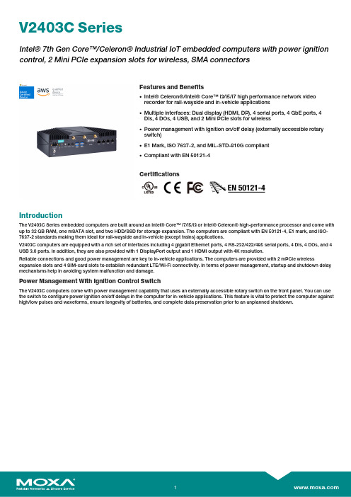
V2403C SeriesIntel®7th Gen Core™/Celeron®Industrial IoT embedded computers with power ignition control,2Mini PCIe expansion slots for wireless,SMA connectorsFeatures and Benefits•Intel®Celeron®/Intel®Core™i3/i5/i7high performance network videorecorder for rail-wayside and in-vehicle applications•Multiple interfaces:Dual display(HDMI,DP),4serial ports,4GbE ports,4DIs,4DOs,4USB,and2Mini PCIe slots for wireless•Power management with Ignition on/off delay(externally accessible rotaryswitch)•E1Mark,ISO7637-2,and MIL-STD-810G compliant•Compliant with EN50121-4CertificationsIntroductionThe V2403C Series embedded computers are built around an Intel®Core™i7/i5/i3or Intel®Celeron®high-performance processor and come with up to32GB RAM,one mSATA slot,and two HDD/SSD for storage expansion.The computers are compliant with EN50121-4,E1mark,and ISO-7637-2standards making them ideal for rail-wayside and in-vehicle(except trains)applications.V2403C computers are equipped with a rich set of interfaces including4gigabit Ethernet ports,4RS-232/422/485serial ports,4DIs,4DOs,and4 USB3.0ports.In addition,they are also provided with1DisplayPort output and1HDMI output with4K resolution.Reliable connections and good power management are key to in-vehicle applications.The computers are provided with2mPCIe wireless expansion slots and4SIM-card slots to establish redundant LTE/Wi-Fi connectivity.In terms of power management,startup and shutdown delay mechanisms help in avoiding system malfunction and damage.Power Management With Ignition Control SwitchThe V2403C computers come with power management capability that uses an externally accessible rotary switch on the front panel.You can use the switch to configure power ignition on/off delays in the computer for in-vehicle applications.This feature is vital to protect the computer against high/low pulses and waveforms,ensure longevity of batteries,and complete data preservation prior to an unplanned shutdown.AppearanceFront ViewRear ViewSpecificationsComputerCPU V2403C-KL1-T:Intel®Celeron®3965U processor(2M Cache,2.2GHz)V2403C-KL3-T:Intel®Core™i3-7100U processor(3M Cache,2.4GHz)V2403C-KL5-T:Intel®Core™i5-7300U processor(3M Cache,2.6GHz)V2403C-KL7-T:Intel®Core™i7-7600U processor(4M Cache,2.8GHz) Storage Slot 2.5-inch HDD/SSD slots x2mSATA slots x1Supported OS Windows10Embedded IoT Ent2019LTSC64-bitWindows10Embedded IoT Ent2021LTSC64-bitLinux Debian9imageLinux Debian11/Ubuntu20.04/CentOS7.9driversSystem Memory Slot SODIMM DDR4slot x2DRAM32GB maxGraphics Controller Celeron Model:Intel HD Graphics610i3/i5/i7Models:Intel HD Graphics620Computer InterfaceEthernet Ports Auto-sensing10/100/1000Mbps ports(RJ45connector)x4 Serial Ports RS-232/422/485ports x4,software selectable(DB9male) Digital Output DOs x4Digital Input DIs x4USB3.0USB3.0hosts x4,type-A connectorsAudio Input/Output Line in x1,Line out x1,3.5mm phone jackVideo Output HDMI x1,HDMI connector(standard)DP x1,DisplayPort connector(standard)Wi-Fi Antenna Connector RP-SMA x3Cellular Antenna Connector SMA x2(optional)GPS Antenna Connector SMA x1(optional)Expansion Slots mPCIe slots x2SIM Format MicroNumber of SIMs4Digital InputsConnector Screw-fastened Euroblock terminalI/O Mode DIIsolation3k VDCSensor Type Wet contact(NPN or PNP)Dry contactDry Contact Logic0:Short to GNDLogic1:OpenWet Contact(DI to COM)Logic0:0to3VDCLogic1:10to30VDCDigital OutputsConnector Screw-fastened Euroblock terminalCurrent Rating200mA per channelI/O Type SinkVoltage0to30VDCIsolation3k VDCLED IndicatorsSystem Power x1Storage x1LAN2per port(10/100/1000Mbps)Serial2per port(Tx,Rx)Serial InterfaceBaudrate50bps to115.2kbpsConnector DB9maleESD Contact:6kV;Air:8kV(level3)Isolation2kVData Bits5,6,7,8Flow Control RTS/CTS,XON/XOFF,ADDC®(automatic data direction control)for RS-485,RTSToggle(RS-232only)Parity None,Even,Odd,Space,MarkStop Bits1,1.5,2Serial SignalsRS-232TxD,RxD,RTS,CTS,DTR,DSR,DCD,GNDRS-422Tx+,Tx-,Rx+,Rx-,GNDRS-485-2w Data+,Data-,GNDRS-485-4w Tx+,Tx-,Rx+,Rx-,GNDPower ParametersInput Voltage12to48VDCPower Connector Terminal blockPower Consumption(Max.)70W(max.)Power Ignition ControlSwitch Type Rotary(front panel)Switch Settings Setting0:IGT function disabledSetting1:PWR ON delay:0.5sec;PWR OFF delay:30secSetting2:PWR ON delay:1sec;PWR OFF delay:30secSetting3:PWR ON delay:1sec;PWR OFF delay:60secSetting4:PWR ON delay:2sec;PWR OFF delay:60secSetting5:PWR ON delay:2sec;PWR OFF delay:90secSetting6:PWR ON delay:3sec;PWR OFF delay:90secSetting7:PWR ON delay:3sec;PWR OFF delay:150secSetting8:PWR ON delay:4sec;PWR OFF delay:180secSetting9:PWR ON delay:5sec;PWR OFF delay:180secPhysical CharacteristicsHousing AluminumIP Rating IP20Dimensions(without ears)250x75x150mm(9.84x2.95x5.91in)Weight2,500g(5.51lb)Installation Wall mounting(standard)Environmental LimitsOperating Temperature-40to70°C(-40to158°F)Storage Temperature(package included)-40to85°C(-40to185°F)Ambient Relative Humidity5to95%(non-condensing)Standards and CertificationsEMC EN55032/35EMI CISPR32,FCC Part15B Class AEMS IEC61000-4-2ESD:Contact:6kV;Air:8kVIEC61000-4-3RS:80MHz to1GHz:20V/mIEC61000-4-4EFT:Power:2kV;Signal:2kVIEC61000-4-5Surge:Power:2kVIEC61000-4-6CS:10VIEC61000-4-8PFMFSafety EN62368-1IEC62368-1UL62368-1Railway EN50121-4Shock IEC60068-2-27,IEC61373,MIL-STD-810G Vibration IEC60068-2-64,IEC61373,MIL-STD-810G DeclarationGreen Product RoHS,CRoHS,WEEEMTBFTime464,506hrsStandards Telcordia(Bellcore),GBWarrantyWarranty Period3yearsDetails See /warrantyPackage ContentsDevice1x V2403C Series computerInstallation Kit2x SSD/HDD trays1x clamp for HDMI cable1x wall-mounting kitDocumentation1x quick installation guide1x warranty cardDimensionsOrdering InformationModel NameCPUMemory (built-in)Optional OS Storage (mSATA)Optional SSD/HDDUSB PortsPower InputOperating Temp.Conformal CoatingV2403C-KL1-T Intel®Celeron®3965U –124x USB 3.0(type A)12to 48VDC (Terminal Block)-40to 70°C –V2403C-KL3-T Intel®Core™i3-7100U –124x USB 3.0(type A)12to 48VDC (Terminal Block)-40to 70°C –V2403C-KL5-T Intel®Core™i5-7300U –124x USB 3.0(type A)12to 48VDC (Terminal Block)-40to 70°C –V2403C-KL7-T Intel®Core™i7-7600U –124x USB 3.0(type A)12to 48VDC (Terminal Block)-40to 70°C –Accessories (sold separately)CablesCBL-PJTB-10Non-locking barrel plug to bare-wire cableWi-Fi Wireless ModulesV2400-WLAN22-AC SparkLAN WPEQ-261ACNI (BT)Wi-Fi mini card,4black screws V2400Cover-DB9Dual DB9expansion cover,4male hex standoff spacer pillars V2406C TPM2.0ModuleSLB9665XT2.0TPM 2.0module without conformal coatingCellular Wireless ModulesV2403C-LTECat4-AP Telit LE910C4LTE Cat.4mini card for the Asia-Pacific region,3SMA antenna cables V2403C-LTECat4-EU Telit LE910C4LTE Cat.4mini card for Europe,3SMA antenna cables V2403C-LTECat4-NFTelit LE910C4LTE Cat.4mini card for North America,3SMA antenna cables©Moxa Inc.All rights reserved.Updated Mar31,2023.This document and any portion thereof may not be reproduced or used in any manner whatsoever without the express written permission of Moxa Inc.Product specifications subject to change without notice.Visit our website for the most up-to-date product information.。
IXGP7N60C;IXGA7N60C;中文规格书,Datasheet资料

© 2002 IXYS All rights reserved98564A (06/02)Symbol Test Conditions Maximum RatingsVCES TJ= 25°C to 150°C600VVCGR TJ= 25°C to 150°C; RGE= 1 MΩ600VVGESContinuous±20VVGEMTransient±30VI C25TC= 25°C 14AI C90TC= 90°C 7AI CM TC= 25°C, 1 ms 30ASSOA VGE = 15 V, TVJ= 125°C, RG= 22 Ω ICM= 14A(RBSOA)Clamped inductive load, L = 300 µH @ 0.8 VCESPC TC= 25°C 54WTJ-55 (150)TJM150CTstg-55 (150)Maximum lead temperature for soldering 300C 1.6 mm (0.062 in.) from case for 10 sMd Mounting torque, (TO-220) M3 0.45/4 Nm/lb.in.M3.5 0.55/5 Nm/lb.in.Weight TO-220 4g TO-263 2 g Symbol Test Conditions Characteristic Values(TJ = 25°C, unless otherwise specified)min.typ.max.BVCESIC= 250 µA, VGE= 0 V600VVGE(th)IC= 250 µA, VCE= VGE2.5 5.5VI CES VCE= 0.8 • VCESTJ= 25°C100µA VGE= 0 V TJ= 125°C500µAI GES VCE= 0 V, VGE= ±20 V±100nAVCE(sat)IC= IC90, VGE= 15 V 2.0 2.7VFeatures•International standard packagesJEDEC TO-263 surfacemountable and JEDEC TO-220 AB•High frequency IGBT•High current handling capability•HiPerFAST TM HDMOS TM process•MOS Gate turn-on-drive simplicityApplications•Uninterruptible power supplies (UPS)•Switched-mode and resonant-modepower supplies•AC motor speed control•DC servo and robot drives•DC choppersAdvantages•High power density•Suitable for surface mounting•Very low switching losses for highfrequency applicationsVCES=600VIC25=14AVCE(sat)= 2.7Vtfi=45nsG = Gate, C = Collector,E = Emitter,TAB = CollectorHiPerFAST TM IGBT Lightspeed TM Series IXGA 7N60CIXGP 7N60CGEC (TAB)TO-263 AA (IXGA)TO-220AB (IXGP)IXYS reserves the right to change limits, test conditions, and dimensions.IXYS MOSFETs and IGBTs are covered by one or more of the following U.S. patents:4,835,5924,881,1065,017,5085,049,9615,187,1175,486,7156,306,728B14,850,0724,931,8445,034,7965,063,3075,237,4815,381,025SymbolTest ConditionsCharacteristic ValuesTO-220 AB Outlinelimeter Inches Min.Max.Min.Max.A 12.7013.970.5000.550B 14.7316.000.5800.630C9.9110.660.3900.420D 3.54 4.080.1390.161E 5.85 6.850.2300.270F 2.54 3.180.1000.125G 1.15 1.650.0450.065H 2.79 5.840.1100.230J 0.64 1.010.0250.040K 2.54BSC 0.100BSC M 4.32 4.820.1700.190N 1.14 1.390.0450.055Q 0.350.560.0140.022R2.29 2.790.0900.110TO-263 AA OutlinePins:1 - Gate2 - Collector3 - Emitter4 - CollectorBottom SideMin. Recommended Footprint (Dimensions in inches and mm)分销商库存信息:IXYSIXGP7N60C IXGA7N60C。
IXGH20N120A3;IXGP20N120A3;IXGA20N120A3;中文规格书,Datasheet资料
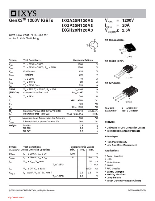
Symbol Test ConditionsMaximum RatingsV CES T J = 25°C to 150°C1200 V V CGR T J = 25°C to 150°C, R GE = 1M Ω1200 V V GES Continuous ±20 V V GEM Transient ±30VI C25T C = 25°C 40A I C110T C = 110°C 20A I CMT C = 25°C, 1ms120ASSOA V GE = 15V, T J = 125°C, R G = 10ΩI CM = 40 A (RBSOA)Clamped Inductive Load @V CE ≤ 960 V P C T C = 25°C180W T J -55 ... +150°C T JM 150°C T stg -55 ... +150°CM d Mounting Torque (TO-247 & TO-220) 1.13/10 Nm/lb.in.F CMounting Force (TO-263) 10..65 / 2.2..14.6N/lb.T L Maximum Lead Temperature for Soldering 300°CT SOLD 1.6mm (0.062 in.) from Case for 10s 260 °CWeightTO-263 2.5 g TO-220 3.0 g TO-2476.0 gSymbol Test Conditions Characteristic Values (T J = 25°C, Unless Otherwise Specified) Min. Typ. Max.BV CES I C = 250μA, V GE = 0V 1200VV GE(th)I C= 250μA, V CE = V GE2.55.0VI CES V CE = V CES , V GE = 0V25 μA T J = 125°C 1 mAI GES V CE = 0V, V GE = ±20V±100 nAV CE(sat)I C = 20A, V GE = 15V, Note 1 2.3 2.5 VT J = 125°C 2.5 VGenX3TM 1200V IGBTsV CES = 1200V I C110= 20A V CE(sat)≤ 2.5VUltra-Low Vsat PT IGBTs forup to 3 kHz SwitchingIXGA20N120A3IXGP20N120A3IXGH20N120A3Featuresz Optimized for Low Conduction Losses zInternational Standard PackagesAdvantagesz High Power DensityzLow Gate Drive RequirementApplicationsz Power Invertersz UPSz Motor Drives z SMPSz PFC Circuits z Battery Chargers z Welding Machines z Lamp BallastszInrush Current Protection CircuitsG = Gate C = Collector E = Emitter Tab = CollectorTO-263 AA (IXGA)G EGC ETO-220AB (IXGP)TO-247 (IXGH)IXYS Reserves the Right to Change Limits, Test Conditions, and Dimensions.Symbol Test Conditions Characteristic ValuesNotes:1. Pulse test, t ≤ 300μs, duty cycle, d ≤ 2%.2. Switching times & energy losses may increase for higher V CE (Clamp), T J or R G .1 = Gate2 = Collector3 = Emitter Tab = CollectorIXYS Reserves the Right to Change Limits, Test Conditions, and Dimensions.IXYS Reserves the Right to Change Limits, Test Conditions, and Dimensions.分销商库存信息:IXYSIXGH20N120A3IXGP20N120A3IXGA20N120A3。
毛家V2403系列无风扇x86工业级物联网嵌入式计算机产品介绍说明书

V2403SeriesFanless,rugged,ready-to-go x86Industrial IoT embeddedcomputersFeatures and Benefits•Intel Core-i Series processor with three performance options•-40to70°C(system and LTE)operating temperature•Dual CFast sockets for storing OS and OS backup•Triple mini-PCIe sockets for storage and wireless modules that supportmSATA,Wi-Fi,3G,LTE,GPS,and Bluetooth•Variety of interfaces:4serial ports,2Ethernet LAN ports,4DIs,4DOs,USB,HDMI,wireless•EN61000-6-2and EN61000-6-4certification;meets EMC standard for heavyindustry•Up to5Grms anti-vibration and100g/11ms anti-shock protection•Ready-to-run Debian8,Windows Embedded Standard7,and Windows10Embedded IoT Enterprise2016LTSB platforms•Moxa Proactive Monitoring utility for system hardware health monitoring•Moxa Smart Recovery utility to recover system from boot failure(W7E only)CertificationsIntroductionThe V2403Series fanless x86embedded computer is based on the Intel®3rd gen Core-i™Series processor,features the most reliable I/O design to maximize connectivity,and supports dual wireless modules,making it suitable for a diverse range of communication applications.The computer’s thermal design ensures reliable system operation in temperatures ranging from-40to70°C(with a special purpose Moxa wireless module installed).The V2403Series supports“Moxa Proactive Monitoring”for device I/O status monitoring and alerts,system temperature monitoring and alerts,and system power management.Monitoring system status closely makes it easier to recover from errors and provides the most reliable platform for your applications.Applications•Remote Terminal Unit(RTU)•Data acquisition•M2M communication(smart gateway)•Digital signage•Factory automation •In-vehicle monitor/data logger(transportation)•Programmable router•Energy usage optimization•Predictive maintenance•Asset managementAppearanceFront View Rear ViewSpecificationsComputerCPU V2403-C2Series:Intel®Celeron®Processor1047UE(2M cache,1.40GHz)V2403-C7Series:Intel®Core™i7-3517UE Processor(4M cache,up to2.80GHz) System Chipset Mobile Intel®HM65Express ChipsetGraphics Controller Intel®HD GraphicsSystem Memory Pre-installed Default4GB DDR3System Memory Slot SODIMM DDR3/DDR3L slot x1Supported OS Linux Debian8(Linux kernel v4.1)Windows Embedded Standard7(WS7E)32-bitWindows Embedded Standard7(WS7E)64-bitStorage Slot 2.5-inch HDD/SSD slots x1CFast slot x2mSATA slots x1Computer InterfaceEthernet Ports Auto-sensing10/100/1000Mbps ports(RJ45connector)x2Serial Ports RS-232/422/485ports x4,software selectable(DB9male)USB2.0USB2.0hosts x4,type-A connectorsAudio Input/Output Line in x1,Line out x1,3.5mm phone jackDigital Input DIs x4Digital Output DOs x4Expansion Slots mPCIe slot x2Video Output DVI-I x1,29-pin DVI-I connectors(female)HDMI x1,HDMI connector(type A)Wi-Fi Antenna Connector RP-SMA x2Cellular Antenna Connector SMA x2Number of SIMs2SIM Format MiniGPS Antenna Connector SMA x1Digital InputsIsolation3k VDCConnector Screw-fastened Euroblock terminalDry Contact On:short to GNDOff:openI/O Mode DISensor Type Dry contactWet Contact(NPN or PNP)Wet Contact(DI to COM)On:10to30VDCOff:0to3VDCDigital OutputsConnector Screw-fastened Euroblock terminalCurrent Rating200mA per channelI/O Type SinkVoltage24to40VDCLED IndicatorsSystem Power x1Storage x1LAN2per port(10/100/1000Mbps)Serial2per port(Tx,Rx)Serial InterfaceBaudrate50bps to921.6kbpsFlow Control RTS/CTS,XON/XOFF,ADDC®(automatic data direction control)for RS-485,RTSToggle(RS-232only)Isolation N/AParity None,Even,Odd,Space,MarkData Bits5,6,7,8Stop Bits1,1.5,2Serial SignalsRS-232TxD,RxD,RTS,CTS,DTR,DSR,DCD,GNDRS-422Tx+,Tx-,Rx+,Rx-,GNDRS-485-2w Data+,Data-,GNDRS-485-4w Tx+,Tx-,Rx+,Rx-,GNDPower ParametersInput Voltage9to36VDCPower Connector Terminal block(for DC models)Power Consumption(Max.) 3.51A@9VDC1.39A@24VDC0.93A@36VDCPower Consumption34W(max.)Physical CharacteristicsHousing AluminumIP Rating IP30Dimensions(with ears)275x63x154mm(10.83x2.47x6.06in) Dimensions(without ears)250x57x154mm(9.84x2.23x6.06in)Weight2,168g(4.82lb)Installation DIN-rail mounting(optional),Wall mounting(standard) Environmental LimitsOperating Temperature-40to70°C(-40to158°F)Storage Temperature(package included)-40to85°C(-40to185°F)Ambient Relative Humidity5to95%(non-condensing)Standards and CertificationsEMC EN55032/24,EN61000-6-2/-6-4EMI CISPR32,FCC Part15B Class AEMS IEC61000-4-2ESD:Contact:4kV;Air:8kVIEC61000-4-3RS:80MHz to1GHz:10V/mIEC61000-4-4EFT:Power:2kV;Signal:1kVIEC61000-4-5Surge:Power:2kV;Signal:1kVIEC61000-4-6CS:1VIEC61000-4-8PFMFSafety EN60950-1,UL508,UL60950-1Shock IEC60068-2-27Vibration IEC60068-2-64DeclarationGreen Product RoHS,CRoHS,WEEEMTBFTime329,398hrsStandards Telcordia(Bellcore),GBWarrantyWarranty Period3yearsDetails See /warrantyPackage ContentsDevice1x V2403Series computerInstallation Kit1x wall-mounting kitCable1x terminal block to power jack converter Documentation1x document and software CD1x quick installation guide1x warranty cardDimensionsOrdering InformationModel Name CPU Memory(Default)OS CFast(CTO)Backup CFast(CTO)SSD/HDD Tray(CTO)USIM SlotAntennaConnectorsOperatingTemp.V2403-C2-T Celeron1047UE4GB1(Optional)1(Optional)1(Optional)––-40to70°CV2403-C2-W-T Celeron1047UE4GB1(Optional)1(Optional)1(Optional)––-40to70°CV2403-C3-T i3-3217UE4GB1(Optional)1(Optional)1(Optional)––-40to70°C V2403-C3-W-T i3-3217UE4GB1(Optional)1(Optional)1(Optional)25-40to70°C V2403-C7-T i7-3517UE4GB1(Optional)1(Optional)1(Optional)25-40to70°C V2403-C7-W-T i7-3517UE4GB1(Optional)1(Optional)1(Optional)25-40to70°CV2403-C2-T-LX Celeron1047UE4GB8GB1(Optional)1(Optional)––-40to70°CV2403-C2-T-W7E Celeron1047UE4GB8GB1(Optional)1(Optional)––-40to70°CV2403-C2-T-W7E1Celeron1047UE8GB32GB1(Optional)64GB MLC––-40to70°CAccessories(sold separately)Battery KitsRTC Battery Kit Lithium battery with built-in connectorPower AdaptersPWR-24270-DT-S1Power adapter,input voltage90to264VAC,output voltage24V with2.5A DC loadPower CordsPWC-C7AU-2B-183Power cord with Australian(AU)plug,2.5A/250V,1.83mPWC-C7CN-2B-183Power cord with two-prong China(CN)plug,1.83mPWC-C7EU-2B-183Power cord with Continental Europe(EU)plug,2.5A/250V,1.83mPWC-C7UK-2B-183Power cord with United Kingdom(UK)plug,2.5A/250V,1.83mPWC-C7US-2B-183Power cord with United States(US)plug,10A/125V,1.83mDIN-Rail Mounting KitsDK-DC50131-01DIN-rail mounting kit,6screwsWall-Mounting KitsV2400Isolated Wall Mount Kit Wall-mounting kit with isolation protection,2wall-mounting brackets,4screwsStorage KitsFK-75125-02Storage bracket,4large silver screws,4soft washers,4small sliver bronze screws,1SATA powercable,4golden spacers(only for the V2406and V2426)AntennasANT-GPS-OSM-05-3M BK Active GPS antenna,26dBi,1572MHz,L1band antenna for GPSANT-LTEUS-ASM-01GSM/GPRS/EDGE/UMTS/HSPA/LTE,omni-directional rubber duck antenna,1dBiANT-WDB-ARM-02 2.4/5GHz,omni-directional rubber duck antenna,2dBi,RP-SMA(male)ANT-WCDMA-ASM-1.5GSM/GPRS/EDGE/UMTS/HSPA,omni-directional rubber duck antenna,1.5dBiANT-LTE-ASM-02GPRS/EDGE/UMTS/HSPA/LTE,omni-directional rubber duck antenna,2dBiWi-Fi Wireless ModulesV2403Wi-Fi mini Card SparkLAN WPEA-252NI Wi-Fi mini card,4black screws©Moxa Inc.All rights reserved.Updated Jun12,2019.This document and any portion thereof may not be reproduced or used in any manner whatsoever without the express written permission of Moxa Inc.Product specifications subject to change without notice.Visit our website for the most up-to-date product information.。
XGB系列产品说明书

No. NameDescriptions① LED IndicatorsShows the operation status②RS-232C Connector The connector for external connection③ RS-422/RS-485 ConnectorThe connector for external connectionNo. Switch status Switch status descriptions④All on Normal operatingAll off OS Download Mode (If you want to OS Download, Please contact us)LED NameLED Descriptions LED status LED status descriptions On Normal operating(a) How to connect RS-232C connector to the external modemCnet I/F module can communicate with devices of long distance through a modem at this time modem and channel RS-232C must be connected as shown in below tableCnet(9-PIN) Connection No. and Signal DirectionModem Pin No. Name Name 1 CDCD 2 RXD RXD 3 TXD TXD 4 DTR DTR 5 SG SG 6 DSR DSR 7 RTS RTS 8 CTS CTS 9 RI RI(b) How to connect RS-232C connector in null modem mode.In null modem mode, connector is able to be connected in 3-line (without handshake) type. Cnet(9-PIN) Connection No. and Signal DirectionComputer /Communicationdevice Pin No. Name Name 1 CDCD 2 RXD RXD 3 TXD TXD 4 DTR DTR 5 SG SG 6 DSR DSR 7 RTS RTS 8 CTS CTS 9RIRI(2) RS-422/485 Interface (XBL-C41A)RS-422 channel uses 5-pin terminal block for communication with external devices. Thenames and functions of pins, and data directions are as shown in the following table. Pin No. Name Signal direction (Cnet<-->External device) Function 1 TX+ Transmitted data (+) 2 TX- Transmitted data (-) 3 RX+ Received data (+) 4 RX- Received data (-) 5 SG Signal ground line [Pin assignment of RS-422 5-pin connector]RS-422 channel makes connection external devices and RS-422 and RS-485(Multi-drop)possible. When RS-422 channel is used as multi-drop, set channel RS-422 to RS-485communication in setting menu of RS-422 communication type of XG-PD, and connect the terminal of RS-422 as shown in the [RS-485 connection] table. Cnet Signal direction(Cnet<--->External device) External device Pin No. Name1 TX+ RX+2 TX- RX-3 RX+ TX+4 RX- TX-5 SG SG [RS-422 connection] Cnet Signal direction (Cnet<--->External device) External devicePin No. Name1 TX+ RX+2 TX- RX-3 RX+ TX+4 RX- TX-5 SG SG [RS-485 connection]Above figure shows how to connect RS-485 multi-drop communication. In the case of RS-485 communication, the TX+ and RX+ terminals should be shortened and TX- and RX- terminals should be shortened, then connected to the other devices. At this time,RS-485 should be selected by using the XG-PD. (3) Terminator (RS-422/485)(a) When the communication via channel RS-422 terminal resistor from external must beconnected. (b) Terminal resistor has the function to prevent distortion of signal by reflected wave of cable when long distance communication, the same resistor (1/2W) as characteristic impedance of cable must be connected to terminal of network.(c) When using the recommended cable in the section 3, connect terminal resistor ofusing another cable than recommended one, the same resistor (1/2W) as characteristic impedance of cable must be connected to both ends of cable.(e) How to connect terminal resistor [RS-485 connection]6. Cautions for system and network connection(1) All the stations in whole network should not have duplicated station number. Otherwise,it can cause serious communication error.(2) Use cable complying with specification in this data sheet. Otherwise, it can serious communication error.8. Warranty(1) Warranty periodLSIS provides an 18-month-warranty from the date of the production. (2) Warranty conditionsFor troubles within the warranty period, LSIS will replace the entire PLC or repair the troubled parts free of charge except the following cases.(a) The troubles caused by improper condition, environment or treatment exceptthe instructions of LSIS.(b) The troubles caused by external devices.(c) The troubles caused by remodeling or repairing based on the user’s owndiscretion.(d) The troubles caused by improper usage of the product.(e) The troubles caused by the reason which exceeded the expectation fromscience and technology level when LSIS manufactured the product. (f) The troubles caused by natural disaster.(3) This warranty is limited to the PLC itself only. It is not valid for the whole systemwhich the PLC is attached to.Be sure to check the rated voltage and terminal arrangement for the► The symbols which are indicated in the PLC and User’s Manual mean as follows. This symbol means paying attention because of danger of electric shock.Store this datasheet in a safe place so that you can take it out and read it whenever necessary. Always forward it to the end user Do not contact the terminals while the power is applied.Warning Caution ∙ HEAD OFFICELS Tower, 127, LS-ro, Dongan-gu, Anyang-si,Gyeonggi-do, 431-848, Korea Tel: 82-2-2034-4870 Fax: (82-2)2034-4648 e-mail: ****************∙ LSIS(ME) FZE _ Dubai, U.A.E. Tel: 971-4-886-5360 Fax: 971-4-886-5361 e-mail: ******************∙ LSIS Tokyo Office _ Tokyo, Japan Tel: 81-3-3582-9128 Fax: 81-3-3582-2667 e-mail: ****************∙ LSIS Shanghai Office _ Shanghai, ChinaTel: 86-21-5237-9977(609) Fax: 89-21-5237-7189 e-mail: ***************.cn∙ LSIS Beijing Office _ Beijing, ChinaTel: 86-10-5825-6027(666) Fax: 86-10-5825-6028 e-mail: **************.cn∙ LSIS Guangzhou Office _ Guangzhou, China Tel: 86-20-8328-6754 Fax: 86-20-8326-6287 e-mail: ***************.cn∙ LSIS Chengdu Office _ Chengdu, China Tel: 86-20-8328-6754 Fax: 86-20-8326-6287 e-mail: ***************∙ LSIS Qingdao Office _ Qingdao, China Tel: 86-532-8501-6068 Fax: 86-532-8501-6057 e-mail: ***************.cn∙ LSIS Europe B.V., Netherlands Tel: +31 (0)20 654 1420 Fax: +31(0)20 654 1429 e-mail: ******************- When using LSIS equipment, thoroughly read this datasheet and associated manuals introduced in thisdatasheet. Also pay careful attention to safety and handle the module properly.- Store this datasheet in a safe place so that you can take it out and read it whenever necessary..。
广州爱普电子技术有限公司产品说明书

Typical Features◆Wide input voltage range:85-265VAC/120-380VDC◆No-load power consumption≤≤0.5W◆Transfer efficiency(typ.87%)◆Switching frequency:65KHz◆Protection:Short Circuit,Over Current◆Isolation voltage:2500Vac◆Plastic case,conform to UL94V-0Class◆PCB mountingApplication FieldFA24-220SXXG3N3Series-----a compact size,high efficient power converter offered by Aipu.It features universal input voltage,DC and AC dual-use,low ripple,low temperature rise,low power consumption, high efficiency,high reliability,safer isolation,with good EMC performance.EMC and Safety standard meet international EN55032,IEC/EN61000.It widely used in power,industrial,instrument,smart home applications.For harsh EMC environment,the application circuit in the datasheet is strongly recommended.Typical Product ListPart No.Output SpecificationMax.Capacitive LoadRipple&Noise20MHz(Max)Efficiency@Full Load220Vac(Typical) Power Voltage1Current1Voltage2Current2(W)Vo1(V)Io1(m A)Vo2(V)Io2(m A)u F mVp-p%FA24-220S12G3N32412.02000--200015085 FA24-220S15G3N32415.01600--20008086 FA24-220S24G3N324241000--80010087 Note1:Ripple&Noise of FA24-220S15G3N3,FA24-220S24G3N3should be tested with EMC solution recommended circuit,please see photo1at back.Note2:Due to space limitations,above is only a part of our product list,please contact our sales team for more items.Note3:.”*”is model under developing.Note4:The typical output efficiency is based on that product is full loaded and burned-in after half an hour.Note5:The fluctuation range of full load efficiency(%,TYP)is±2%,full load output efficiency=total output power/module’s input power.Input SpecificationItem Operating Condition Min.Typ.Max.UnitInput Voltage Range AC Input85220265VAC DC Input120310380VDCInput Frequency Range-475063HzInput Current 115VAC//250mA 220VAC//150Surge Current 115VAC//10 220VAC//20Leakage Current-0.5mA TYP/230VAC/50HzExternal fuserecommended value-2A-5A/250VAC slow-fusing Hot plug-UnavailableRemote control terminal-UnavailableOutput SpecificationItem Operating Condition Min.Typ.Max.UnitVoltage Accuracy Full input voltagerangeAny loadVo1--±2.0%Vo2---%Line Regulation Nominal Load Vo1--±2.0% Vo2---%Load RegulationNominal inputVoltage20%~100%loadVo1--±2.0%Vo2---%No load power consumption Input115VAC--0.5W Input220VAC--Minimum loadSingle Output0--% Positive Negative Dualoutput commongrounded---% Positive Negative Dualoutput isolated---Turn-on Delay Time Nominal input voltage,fullload-300-mSPower-off Holding Time Input115VAC(full load)-65-mS Input220VAC(full load)--Output Overshooting Full input voltage range(full load)--10%Dynamic Response 25%~50%~25%50%~75%~50%Overshoot range(%):≤±5%%Recovery time(mS):≤5.0mS mSShort Circuit Protection Input full voltage range Continuous,Self-recovery Hiccup Drift Coefficient--±0.03%-%/℃Over Current Protection Input220VAC≥120%Io,Self-recovery HiccupRipple&Noise Vo=12.0V≤150mV Vo=15.0V≤80mVVo=24.0V≤100Note:Ripple&Noise is tested by Twisted Pair Method,details please see Ripple&Noise Test at back. General SpecificationsItem Operating Condition Min.Typ.Max.Unit Switching Frequency-606570KHz Operating Temperature--40-+75℃Storage Temperature--40-+85Relative Humidity-10-90%RHIsolation Voltage Input-Output,Test1min,leakage current≤5mA2500--VACInsulation Resistance Input-Output@DC500V100--MΩMTBF-≥300,000H@25℃Vibration-10-55Hz,10G,30Min,alongX,Y,ZClass of Case Material-UL94V-0EMC CharacteristicsTotal Item Sub Item Test Standard ClassEMC EMICE CISPR22/EN55032CLASS B(see recommended circuit Photo2)RE CISPR22/EN55032CLASS B(see recommended circuit Photo2)EMSRS IEC/EN61000-4-310V/m Perf.Criteria BCS IEC/EN61000-4-63Vr.m.s Perf.Criteria BESD IEC/EN61000-4-2Contact±4KV/Air±8KV Perf.Criteria BSurge IEC/EN61000-4-5±1KV Perf.Criteria B(see recommendedcircuit Photo2)EFT IEC/EN61000-4-4±2KV Perf.Criteria BVoltage dips,shortinterruptions and voltagevariations immunityIEC/EN61000-4-110%~70%Perf.Criteria BPacking DimensionPacking Code L x W x HG339.0x25.0x22.0mmPin DefinitionPin-out12345Single(S)AC(N)AC(L)GND NP+VoNote:If the definition of pin is not in accordance with the model selection manual,please refer to the label on actual item. Ripple&Noise Test:(Twisted Pair Method20MHZ bandwidth)Test Method:(1)12#twisted pair to connect,Oscilloscope bandwidth set as20MHz,100M bandwidth probe,terminated with0.1uFpolypropylene capacitor and10uF high frequency lowresistance electrolytic capacitor in parallel,oscilloscope set asSample pattern.(2)Input terminal connect to power supply,output terminalconnect to electronic load through jig plate,Use30cm±2cmsampling line.Power line selected from correspondingdiameter wire with insulation according to the flow of outputcurrent.Product Characteristic CurveNote1:Input Voltage should be derated base on Input Voltage Derating Curve when it is85~100VAC/240~265VAC/120~140VDC/340~380VDC.2:Our product is suitable to use under natural air cooling environment,if use it under closed condition,please contact with us. Typical EMC Circuit and Recommended Spec1.Typical Application CircuitPart No.CE1L1CE2TVS1FA24-220S12G3N3NC2uH470uF/16V SMBJ14.0AFA24-220S15G3N3220uF/25V5uH220uF/25V SMBJ17.0A*FA24-220S24G3N3220uF/35V5uH220uF/35V SMBJ26.0ANote:Output filter capacitor C2is electrolytic capacitor,recommend high frequency low resistor electrolytic capacitor,for capacity and current low,please refer to the technical specifications provided by each manufacturer.C2capacitor withstand voltage should derate to80%,capacitor C1is ceramic capacitor,to filter high frequency noise,recommended0.1uF/50V/1206.TVS1tube is a recommend component to protect post-circuit if converter fails.Recommend to external FUSE,Model:3.15A/250V, slow fusing.2.EMC solution recommended circuitPhoto2,EMC for higher requirement circuitComponent Products Module ValueFUSE 3.15A/250Vac 3.15A/250Vac,slow-fusing,necessaryNTC5D-95D-9MOV10D561K10D561KCX10.47uF/275Vac0.47uF/275VacL1 6.8uH/3.0A 6.8uH/3.0A H inductorLF2UU9.830mH min30mH/3.0ANote:1.The product should be used under the specification range,otherwise it will cause permanent damage to it.2.Product’s input terminal should connect to fuse;3.If the product is not worked under the load range(below the minimum load or beyond the load range),we cannot ensure that the performance of product is in accordance with all the indexes in this manual;4.Unless otherwise specified,data in this datasheet are tested under conditions of Ta=25℃,humidity<75%when inputting nominal voltage and outputting rated load(pure resistance load);5.All index testing methods in this datasheet are based on our Company’s corporate standards6.The performance indexes of the product models listed in this manual are as above,but some indexes of non-standard model products will exceed the above-mentioned requirements,please directly contact our technician for specific information;7.We can provide customized product service;8.The product specification may be changed at any time without prior notice.。
光敏二极管SGPD30C产品手册说明书

产品说明书平面贴片光敏二极管:SGPD30C⏹特点․快速响应․高感光灵敏度․较小的结电容․无铅环保,符合RoHS标准⏹描述SGPD30C是一款高速高灵敏度光敏二极管,具有较低结电容,小型化贴片(SMT)式结构,用透明环氧材料封装,长时间使用无测量参数衰减,可实用于多种不同用途,如声音传送、视频记录、遥控、测量、控制等。
⏹应用․高速光学传感器․复印机․光学仪器仪表․电梯、升降机正极负极Flat area 0.3 min.注: 1. 所有尺寸单位为毫米(英寸) 2. 未注明误差的尺寸±0.25mm(0.01英寸)⏹封装尺寸⏹极限参数(Ta=25℃)参数符号参数值单位反向电压VR 30V 耗散功率Pd 150mW 焊接温度Tsol 260℃工作温度Topr -25~+85℃存储温度Tstg-40~+85℃Ambient Temperature Ta(°C)P o w e r D i s s i p a t i o n (m W )5020020406080100-20-401001501008060200100Wavelength(nm)R e l a t i v e S p e c t r a l S e n s i t i v i t y (%)Ta=25°4030050070090011001300⏹光电参数(Ta=25℃)参数符号条件最小典型最大单位光谱带宽λ0.5---400---1100nm 感光峰值波长λp ------940---nm 开路电压V OC Ee=5m W/cm 2λp=940nm ---0.35---V短路电流I SC Ee=5m W/cm 2λp=940nm ---95---μA反向亮电流I LEe=5m W/cm 2λp=940nm V R =5V 8095---μA暗电流Id Ee=0m W/cm 2V R =10V------10nA反向击穿电压BV R Ee=0m W/cm 2I R =100μA 30------V 总计电容CtEe=0m W/cm 2V R =3V f=1MHZ ---25---pF 上升/下降时间t r /t fV R =10V R L =1K Ω50/50nS⏹光电特性曲线图.1耗散功率与环境温度图.2相对频谱灵敏度400Ambient Temperature Ta(°C)R e v e r s e D a r k C u r r e n t (n A )608010020101001000V =10V R1Reverse Voltage (V)T e r m i n a l C a p a c i t a n c e C t (p F )101000.120406080f=1MHz V =3V Ee=0mW cmR2/10Load Resistance R L ( )R e s p o n s e T i m e t r ,t f (u s )10310410101101010101010-3V =10V RT =25 Ca °Ω160120804002.55.07.5Ee(mW/cm )R e v e r s e L i g h t C u r r e n t (u A )10.02V =5V Rλ=940nm图.3暗电流与环境温度图.4反向感光电流与辐射强度图.5结电容与反向电压图.6响应时间与负载电阻注: 1. 所有尺寸单位为毫米(英寸)正极负极注: 1. 所有尺寸单位为毫米(英寸) 2. 未注明误差的尺寸为 ± 0.1mm(.004")⏹包装尺寸⏹载带尺寸图(数量:1000个/盘)注意事项:1.我公司保留更改产品材料和以上说明书的权利,更改以上产品说明书恕不另行通知。
13003BR中文资料

Absolute Maximum Ratings (Ta=25°C)• Maximum TemperaturesStorage Temperature............................................................................................ -50 ~ +150 °C Junction Temperature...................................................................................... 150 °C Maximum • Maximum Power DissipationTotal Power Dissipation (Tc=25°C)..................................................................................... 40 W • Maximum Voltages and Currents (Ta=25°C)VCEX Collector to Emitter Voltage.................................................................................... 700 V VCEO Collector to Emitter Voltage.................................................................................... 400 V VEBO Emitter to Base Voltage.............................................................................................. 9 V IC Collector Current ........................................................................................ Continuous 1.5 A IB Base Current............................................................................................. Continuous 0.75 A Characteristics (Ta=25°C)Symbol Min.Typ.Max.Unit Test ConditionsBVCEX700--V IC=1mA, VBE(off)=1.5VBVCEO400--V IC=10mAIEBO--1mA VEB=9VICEX--1mA VCE=700V, VBE(off)=1.5V *VCE(sat)1--500mV IC=0.5A, IB=0.1A*VCE(sat)2--1V IC=1A, IB=0.25A*VCE(sat)3--3V IC=1.5A, IB=0.5A*VBE(sat)--1V IC=0.5A, IB=0.1A*VBE(sat)-- 1.2V IC=1A, IB=0.25A*hFE18-40IC=0.5A, VCE=2V*hFE25-25IC=1A, VCE=2V*Pulse Test: Pulse Width ≤380us, Duty Cycle≤2%Page No. : 2/3 Characteristics CurvePage No. : 3/3 TO-126 DimensionImportant Notice:• All rights are reserved. Reproduction in whole or in part is prohibited without the prior written approval of HSMC.• HSMC reserves the right to make changes to its products without notice.•HSMC semiconductor products are not warranted to be suitable for use in Life-Support Applications, or systems.• HSMC assumes no liability for any consequence of customer product design, infringement of patents, or application assistance. Head Office And Factory:•Head Office (Hi-Sincerity Microelectronics Corp.): 10F.,No. 61, Sec. 2, Chung-Shan N. Rd. Taipei Taiwan R.O.C.Tel: 886-2-25212056 Fax: 886-2-25632712, 25368454•Factory 1: No. 38, Kuang Fu S. Rd., Fu-Kou Hsin-Chu Industrial Park Hsin-Chu Taiwan. R.O.CTel: 886-3-5983621~5 Fax: 886-3-5982931。
Sophos XG系列硬件设备操作说明书

Operating InstructionsXG 105(w)/115(w)/125(w)/135(w) Rev. 3/XG 106(w) Rev.1ForewordWe are pleased to welcome you as a new customer of our Sophos XG appliances.To install and configure the hardware appliance you can use the following documents:ÌHardware Quick Start Guide: Connection to thesystem peripherals in a few stepsÌOperating Instructions: Notes on the security andcommissioning of the hardware applianceÌAdministration Guide: Installing and configuring the software applianceThe Hardware Quick Start Guide and the Safety Instructions are also deliveredin printed form together with the hardware appliance. The instructions must be read carefully prior to using the hardware and should be kept in a safe place.You may download all user manuals and additional documentation from the support webpage at: /supportSecurity SymbolsThe following symbol and its meaning appears in the Hardware Quick Start Guide, Safety Instructions and in these Operating Instructions.Caution and Important Note. If these notes are not correctly observed:ÌThis is dangerous to life and the environmentÌThe appliance may be damagedÌThe functions of the appliance will be no longer guaranteedÌSophos shall not be liable for damages arising from afailure to comply with the Safety InstructionsDesigned UseThe hardware appliances are developed for use in networks.The XG 105(w)/106(w)/115(w)/125(w)/135(w) models may be operated asa standalone appliance. The hardware appliance can be used in commercial, industrial and residential environments.The XG 105(w)/106(w)/115(w)/125(w)/135(w) models belong to the appliance group B.The hardware appliance must be installed pursuant to the current installation notes. Otherwise failure-free and safe operation cannot be guaranteed. The EU declaration of conformity is available at the following address:Sophos Technology GmbHAmalienbadstr. 41/Bau 5276227 KarlsruheGermanyCE Labeling, FCC and ApprovalsThe XG 105(w)/106(w)/115(w)/125(w)/135(w) appliances comply with CB, CE, FCC Class B, ISED, VCCI, RCM, UL, CCC, and BIS.Important Note: For computer systems to remain CE and FCC compliant, only CE and FCC compliant parts may be used. Maintaining CE and FCC compliance also requires proper cable and cabling techniques.Operating Elements and ConnectionsXG 105(w)/115(w)*(Rev. 3)/XG 106(w) Rev.1Status LEDs (w-model has additional Wi-Fi LED)1 x COM (RJ45)2 x USB 2.0 1 x Micro USB4 x GbE copper port1 x GbE SFP (shared)1 x HDMI Power Supply Connector for optional 2nd redundant power supply2 x external antenna(XG 125w and XG 135w only)XG 125(w)/135(w)*(Rev. 3)Status LEDs (w-model has additional Wi-Fi LED)1 x COM(RJ45)3 x external antenna(XG 125w andXG 135w only)2 x USB 2.08 x GbE copper port Power Supply Optional 2nd redundant power supply1 x MicroUSB1 x HDMI Expansion bay (shown with optionalmodule incl. 2 antennas)1 x GbE SFP * The displayed front images are of the XG 115 and 135 device. The displayed back images are of the XG 115w device and the XG 135w. Devices may vary slightly.LED StatusSpeed (Right LED)Amber On The Ethernet port is operating at 1,000 Mbps. Green On The Ethernet port is operating at 100 Mbps.Off The Ethernet port is operating at 10 Mbps.Speed(Right LED)Amber On The Ethernet port is operating at 1,000 MbpsPutting into OperationCaution: Risk of explosion if battery is replaced by an incorrect type. Dispose of used batteries according to the instructions.Scope of SupplyThe supplied parts are indicated in the Hardware Quick Start Guide. Mounting InstructionsThe XG 105(w)/106(w)/115(w)/125(w)/135(w) appliances can be placed on a stable horizontal surface or can be mounted to a rack or you can hang it on the wall by using the optionally available rackmount kit.Warnings and PrecautionsThe appliance can be operated safely if you observe the following notes and the notes on the appliance itself.Rack PrecautionsÌEnsure that the leveling jacks on the bottom of the rack are fullyextended to the floor with the full weight of the rack resting on them.ÌIn single rack installation, stabilizers should be attached to the rack.ÌIn multiple rack installations, the racks should be coupled together.ÌAlways make sure the rack is stable beforeextending a component from the rack.ÌYou should extend only one component at a time—extending two ormore simultaneously may cause the rack to become unstable.General Server PrecautionsÌReview the electrical and general safety precautions that camewith the components you are adding to your appliance.ÌDetermine the placement of each component inthe rack before you install the rails.ÌInstall the heaviest server components on thebottom of the rack first, and then work up.ÌAllow the hot plug hard drives and power supplymodules to cool before touching them.ÌAlways keep the rack‘s front door, all panels and server componentsclosed when not servicing to maintain proper cooling.Rack Mounting ConsiderationsÌAmbient operating temperature: If installed in a closed or multi-unit rack assembly, the ambient operating temperature of the rack environmentmay be greater than the ambient temperature of the room. Therefore,you should install the equipment in an environment compatiblewith the manufacturer’s maximum rated ambient temperature.ÌReduced airflow: Equipment should be mounted intoa rack with sufficient airflow to allow cooling.ÌMechanical loading: Equipment should be mounted into a rack so that a hazardous condition does not arise due to uneven mechanical loading.ÌCircuit overloading: Consideration should be given to the connectionof the equipment to the power supply circuitry and the effect that anypossible overloading of circuits might have on overcurrent protectionand power supply wiring. Appropriate consideration of equipmentnameplate ratings should be used when addressing this concern.ÌReliable ground: Reliable grounding must be maintained at all times.To ensure this, the rack itself should be grounded. Particular attentionshould be given to power supply connections other than the directconnections to the branch circuit (i.e., the use of power strips, etc.).Connection and ConfigurationHow to connect the appliance is described in the Hardware Quick Start Guide. For configuration you can follow the initial setup wizard described in the WebAdmin Quick Start Guide or cancel it and perform a manual setup (see the Sophos XG Firewall Administrator Guide).SFP PortThe XG1xx rev.3 and XG 106(w) rev.1 models provide a SFP port allowing you to either insert a SFP Mini-GBIC (transceiver) to connect to a 1 GbE fiber or copper cable or to insert a VDSL2 SFP modem to directly connect to a VDSL line (via a RJ11 cable).These modules are not delivered with the appliance but available through your Sophos partner.Please note that there are different Mini-GBIC module types. The required type is determined by the existing network. The following SFP GBIC module types may be used:SFP:1000 Base-TIEEE 802.3 - 1 Gbit/s via Ethernet cable. An Ethernet cable category 5 covers a maximum distance about 100 meters.1000 Base-SXIEEE 802.3 - 1 Gbit/s via fiberglass. Multi-mode fiberglass cables (MMF) cover a distance of 200 m to 550 m.1000 Base-LXIEEE 802.3 - 1 Gbit/s via fiberglass. Here, exclusively singlemode-fiber glass is used. This transmission option covers approximately 10 km.Expansion ModulesThe XG 125(w)/135(w) support an additional expansion module allowing you to insert an optional 3G/4G or Wireless module (on XG 135w only). These modules are not delivered with the appliance but available through your Sophos partner. Please note that there are different 3G/4G modules available depending on the region you want to operate it in Americas/EMEA and APAC.Please see table below for further details.For installing the module please read the mounting instructions which are shipped with each module.Serial ConsoleYou can connect a serial console to either of the COM ports of the Sophos XG hardware appliances. You can use, for instance, the Hyperterminal terminal program which is included with most versions of Microsoft Windows to log on to the appliance console. Use an RJ45 to DB9 adapter cable or the provided USB cable to connect the console to your hardware appliance.The required connection settings are:ÌBits per second: 38,400ÌData bits: 8ÌParity: N (none)ÌStop bits: 1Access via the serial console is activated by default on ttyS1. The connections of the appliances and the respective functionality are listed in chapter “Operating Elements and Connections.”United Kingdom and Worldwide Sales Tel: +44 (0)8447 671131Email:****************North American SalesToll Free: 1-866-866-2802Email:******************Australia and New Zealand SalesTel: +61 2 9409 9100Email:****************.auAsia SalesTel: +65 62244168Email:********************© Copyright 2018. Sophos Ltd. All rights reserved.Registered in England and Wales No. 2096520, The Pentagon, Abingdon Science Park, Abingdon, OX14 3YP, UK Sophos is the registered trademark of Sophos Ltd. All other product and company names mentioned are trademarks or registered trademarks of their respective owners.。
28130;中文规格书,Datasheet资料
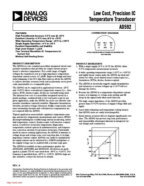
METALIZATION DIAGRAM
TEMPERATURE SCALE CONVERSION EQUATIONS
+2.0 +1.5 +1.0 +0.5
0 –0.5 –1.0 –1.5 –2.0
–25
0
+25
+70
TEMPERATURE – oC
+105
AD592BN Accuracy Over Temperature
TOTAL ERROR – oC TOTAL ERROR – oC
+2.0 +1.5 +1.0 +0.5
+1.0
+0.5
MAXIMUM ERROR OVER TEMPERATURE
TYPICAL ERROR
0 CALIBRATION ERROR LIMIT
–0.5
TOTAL ERROR – oC
IOUT – µA
378
+105oC
298
+25oC
–25oC 248
UP TO 30V
0
1
2
3
4
5
6
SUPPLY VOLTAGE – Volts
66MILS
V+
V–
/
Model
AD592CN AD592BN AD592AN
42MILS
؇C = 5 (؇F –32) 9
MBRA140T3G;MBRA140T3;中文规格书,Datasheet资料
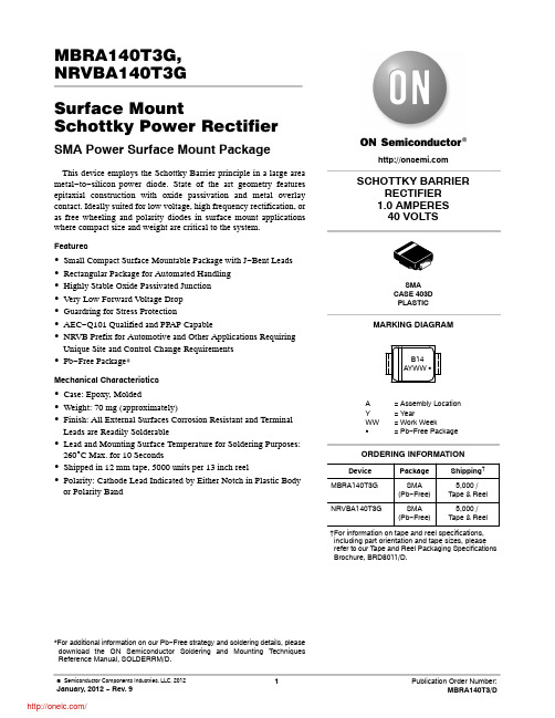
Figure 5. Current Derating
R (T) , TRANSIENT THERMAL RESISTANCE (NORMALIZED) T, TIME (s) 1.0E+0
Figure 6. Forward Power Dissipation
中文规格书datasheet资料datasheetdatasheet网站l298ndatasheeticdatasheetpl2303datasheetds18b20datasheetdatasheetcomlm324datasheetrt5350datasheet
MBRA140T3G, NRVBA140T3G Surface Mount Schottky Power Rectifier
vF, INSTANTANEOUS FORWARD VOLTAGE (VOLTS)
Figure 1. Typical Forward Voltage
Figure 2. Maximum Forward Voltage
100E-3 I R , REVERSE CURRENT (AMPS)
100E-3 I R , MAXIMUM REVERSE CURRENT (AMPS)
†For information on tape and reel specifications, including part orientation and tape sizes, please refer to our Tape and Reel Packaging Specifications Brochure, BRD8011/D.
10E-3
TJ = 125C TJ = 85C
10E-3 TJ = 85C 1.0E-3 TJ = 25C
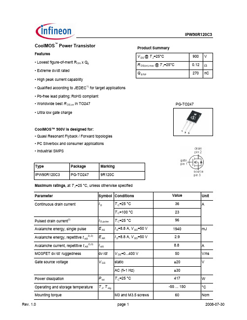
INFINEON IPW90R120C3 说明书
100
0.5
6V
10-1
Z thJC [K/W]
0.2 0.1 0.05 0.02
5.5 V
I D [A]
50
10-2
0.01 single pulse
5V
4.5 V
4V
10
-3
0 10-4 10-3 10-2 10-1 0 5 10 15 20 25
10-5
t p [s]
V DS [V]
Rev. 1.0
1
0.75 40
R DS(on) [Ω ]
4.5 V
I D [A]
0.5
5V 4.8 V 4.5 V
20
4V
4V
0.25
0 0 5 10 15 20 25
0 0 20 40 60 80
V DS [V]
I D [A]
7 Drain-source on-state resistance R DS(on)=f(T j); I D=26 A; V GS=10 V
IPW90R120C3
Maximum ratings, at T j=25 °C, unless otherwise specified Parameter Continuous diode forward current Diode pulse current 2) Reverse diode d v /dt 4) Parameter Symbol Conditions IS I S,pulse dv /dt Symbol Conditions min. Thermal characteristics Thermal resistance, junction - case Thermal resistance, junction ambient Soldering temperature, wavesoldering only allowed at leads R thJC R thJA leaded 1.6 mm (0.063 in.) from case for 10 s 0.3 62 K/W T C=25 °C Value 26 81 4 Values typ. max. V/ns Unit Unit A
L-132XGC资料
Units mW mA mA V
SPEC NO: DSAB3281 APPROVED: WYNEC
REV NO: V.8 CHECKED: Allen Liu
DATE: JUN/28/2007 DRAWN: Y.H.CHEN
PAGE: 2 OF 5 ERP: 1101001070
元器件交易网
REV NO: V.8 CHECKED: Allen Liu
DATE: JUN/28/2007 DRAWN: Y.H.CHEN
PAGE: 5 OF 5 ERP: 1101001070
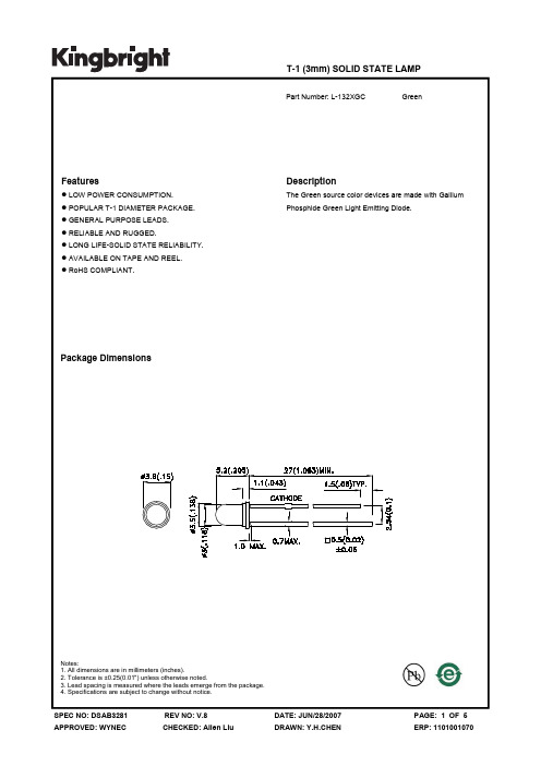
Notes: 1.Wavelength: +/-1nm. 2. Forward Voltage: +/-0.1V.
Absolute Maximum Ratings at TA=25°C
Parameter Power dissipation DC Forward Current Peak Forward Current [1] Reverse Voltage Operating/Storage Temperature Lead Solder Temperature [2] Lead Solder Temperature [3]
Notes: 1. 1/10 Duty Cycle, 0.1ms Pulse Width. 2. 2mm below package base. 3. 5mm below package base.
Green 62.5 25 140 5 -40°C To +85°C 260°C For 3 Seconds 260°C For 5 Seconds
Part No. Dice Lens Type Iv (mcd) [2] @ 10mA Min. L-132XGC Green (GaP) WATER CLEAR 12 Typ. 40 Viewing Angle [1] 2θ1/2 50°
- 1、下载文档前请自行甄别文档内容的完整性,平台不提供额外的编辑、内容补充、找答案等附加服务。
- 2、"仅部分预览"的文档,不可在线预览部分如存在完整性等问题,可反馈申请退款(可完整预览的文档不适用该条件!)。
- 3、如文档侵犯您的权益,请联系客服反馈,我们会尽快为您处理(人工客服工作时间:9:00-18:30)。
GenX3TM 300V IGBT
IXGH120N30C3
(TAB)
High speed PT IGBTs for
50-150kHz switching
V CES = 300V I C110= 120A V CE(sat) ≤ 2.1V t fi (typ)= 86ns
Symbol
Test Conditions Characteristic Values (T J = 25°C, unless otherwise specified)
Min. Typ. Max.
BV CES I C = 250μA, V GE = 0V 300V V GE(th)I C
= 250μA, V CE = V GE
2.5
5.0
V
I CES V CE = V CES 50μA V GE = 0V
T J = 125°C
1.0 mA I GES V CE = 0V, V GE = ±20V ±100
nA
V CE(sat)
I C
= 120A, V GE = 15V
1.75
2.10V T J = 125°C
1.70 V
Symbol Test Conditions Maximum Ratings V CES T J = 25°C to 150°C
300V V CGR T J = 25°C to 150°C, R GE = 1M Ω 300
V V GES Continuous ±20V V GEM Transient
±30
V I C25T C = 25°C (limited by leads) 75A I C110T C = 110°C (chip capability) 120A I CM T C = 25°C, 1ms 600
A
I A T C = 25°C 120 A E AS
T C = 25°C
850 mJ
SSOA V GE = 15V, T VJ = 125°C, R G = 2Ω I CM = 240A (RBSOA)Clamped inductive load @ ≤ 300V P C T C = 25°C
540
W T J -55 ... +150
°C T JM 150
°C T stg -55 ... +150
°C
T L
Maximum lead temperature for soldering 300°C
T SOLD 1.6mm (0.062 in.) from case for 10s 260 °C M d Mounting torque
1.13/10
Nm/lb.in.
Weight
6
g
TO-247 AD (IXGH)
G = Gate, C = Collector,E = Emitter,
TAB = Collector
Features
z High Frequency IGBT z Square RBSOA
z High avalanche capability
z
Drive simplicity with MOS Gate Turn-On
z
High current handling capability
Applications
z PFC Circuits z PDP Systems
z
Switched-mode and resonant-mode converters and inverters z SMPS
z AC motor speed control z
DC servo and robot drives z
DC choppers
IXYS reserves the right to change limits, test conditions, and dimensions.
Symbol Test Conditions Characteristic Values (T
J
= 25°C, unless otherwise specified)
fs I
C
= 60A, V
CE Pulse test, t ≤
ies
oes V
CE
= 25V, V
GE
res
g
I = I, V
PRELIMINARY TECHNICAL INFORMATION
The product presented herein is under development. The Technical Specifications offered are derived from data gathered during objective characterizations of preliminary engineering lots; but also may yet contain some information supplied during a pre-production design evaluation. IXYS reserves the right to change limits, test conditions, and dimensions without notice.
Fig. 1. Output Characteristics
80100120140160
180
200220240I C - A m p e r e s
IXYS reserves the right to change limits, test conditions, and dimensions.
Fig. 7. Transconductance
6080100
120140g f s - S i e m e n s
T J = - 40ºC 25ºC 125ºC
© 2008 IXYS CORPORATION, All rights reserved
Fig. 12. Inductive Switching Energy Loss vs. Gate Resistance
0.81.01.2
1.41.6E o f f - M i l l i J o u l e s
E off E on - - - - T J = 125ºC , V GE = 15V V CE = 200V
IXYS reserves the right to change limits, test conditions, and dimensions.
Fig. 18. Inductive Turn-on
Switching Times vs. Gate Resistance
35404550
5560- N a n o s e c o n d s
t r t d(on) - - - - T J = 125ºC, V GE = 15V V CE = 200V
I C = 60A
IXYS REF: G_120N30C3(76)7-13-07
分销商库存信息: IXYS
IXGH120N30C3。
