SAS92_476195_70021996_Win_Wrkstn
SAS9.2的破解,验证可用!
SAS9.2的破解,验证可用!
软件准备:下载UltraEdit。
方法步骤:
用UltraEdit打开sashost.dll→搜索0FB74DDA0558F8FFFF→替代为66B90#0066B8**0090. sashost.dll 路径:%SASFoundation\9.2 (和sas9.2.exe是一个目录)
#为月份,1,2,3,4,5,6,7,8,9,A,B,C为一月到12月。
或者用0 也代表一月。
**为你要的年份。
注意年份的计算公式是:HEX(实际年份-1960)
所以2008年:hex(2008-1960)=30h
2009年:31h
2010年: 32h
etc..... 具体什么意思也不用管它
所以先确定你SAS 的生日birthday=。
和过期日expire=。
当你安装SAS的时候,你用的SID文件里都有这两个日期。
每次SAS启动时,都会检查你的当前系统日期是不是在这两个日期之间。
如果不在,SAS就启动失败。
这就是为什么要破解的原因。
不确定的可以找到安装文件里面的SID.txt文件看一下。
如果2009年1月在你SAS9.2的生日和过期日之间,你用这个字符串:66B9000066B8310090;
如果2010年12月在你SAS9.2的生日和过期日之间,你用这个字符串:66B90C0066B8320090;
比如我的9.2是网上比较流行的2.97G那个2008年1月30号到2009年1月30号的,那么我只需要把上面那串代码修改为这两个日期之间就行。
Using KVM Configure Openfiler 2.99 Active Passive Cluster

Using KVM Configure Openfiler 2.99 Active/Passive Cluster自从安装了openfiler 2.99之后,发现跟以前版本的不同之处之一是web管理界面的选项栏里多了个cluster选项,而在openfiler的官方文档里也没有提到openfiler cluster的相关信息。
google了下,发现竟有类似的文章,自己搭了个环境研究了下,以下是具体操作过程:一、准备工作:1、主机名和IP对应关系见下图:其中的虚拟IP是用于openfiler对外提供服务的虚拟IP。
可以在web管理界面的status拦里看到监听的IP地址是 192.168.1.90.如果openfiler服务同一时刻存在于某个节点上,也可以使用它本身的公网IP进行访问。
如下图所示,服务当前位于 nas01上,所以也可以是192.168.1.91访问openfiler的web管理界面。
2、磁盘:nas01和nas02各带一个20G的虚拟磁盘sdb,分了两个分区:Meta分区sdb1(500Mb)和Data分区sdb2。
在这里注意,如果你的共享磁盘类型是virtio 类型BUS,则使用openfiler管理界面设置LVM时无法对其进行识别,这里使用默认的IDE BUS即可。
如图:3、将以上IP和主机名加入两个节点的hosts文件中:4、创建SSH等同性:NAS01:NAS02:设置完成后,两个节点就可以使用ssh进行无密码登录了。
二、DRBD的设置:1、两个节点上编辑/etc/drbd.conf,加入以下内容:2、创建resource:meta和data:创建完成后,两节点启动drbd服务。
接着使其中一个节点成为主角色:以上两条命令,在任意一个节点执行即可,完成后,可以查看/proc/drbd获取同步信息:上面的drbd0大小是500M,同步很快,而drbd1大小近20G,同步起来需要点时间。
P2V常见问题
Converter Standalone 5.0 版本中包含以下已知问题:•安装•常规•Windows 源•Linux 源•第三方格式•本地化•用户指南和帮助安装在重新安装 Converter Standalone 之前,必须重新启动运行 64 位 Windows Vista 或更高版本的计算机如果从 64 位 Windows Vista、Windows Server 2008 或 Windows 7 计算机上卸载Converter Standalone 后没有重新启动计算机,则后续的 Converter Standalone 安装可能会失败,并会显示以下错误消息:错误 29144。
无法安装服务 Vstor2 MntApi 1.0 Driver(共享)。
请重新引导并尝试再次安装 (Error 29144. Could not install service Vstor2 MntApi 1.0 Driver (shared). Please reboot and try to install again)。
解决办法:重新启动 Windows Vista、Windows Server 2008 或 Windows 7 计算机,然后尝试重新安装 Converter Standalone。
Converter Standalone 安装程序未发出任何通知即移除 Workstation 6.5.x 远程代理使用 Workstation 6.5.x 热克隆 Windows 源计算机时,Workstation 会在源上部署一个远程 Workstation 代理。
如果选择保留该源上的远程代理,然后将 Converter Standalone 安装在同一计算机上,则 Converter Standalone 安装程序将卸载该代理且不发送任何警告消息。
成功转换之后,运行 64 位 Windows Vista 或更高版本的远程源计算机的后续 P2V 转换可能会失败如果成功转换某一运行 64 位 Windows Vista、Windows Server 2008 或 Windows 7 操作系统的远程源计算机后尝试再次转换,则转换将失败,并且会显示错误消息:Converter Standalone Agent 在 x.x.x.x 上安装失败,错误代码: 1603 (Converter Standalone Agent installation failed on x.x.x.x Error code: 1603)1603,其中 x.x.x.x 是源计算机的 IP 地址。
THINKPAD开机错误消息及报警信息详解

THINKPAD开机错误消息及报警信息详解注:在图表中,x 可以是任何字符。
0175: Bad CRC1, stop POST task(CRC1 错误,停止POST 任务)0176: System Security - The system has been tampered with.(系统安全性- 系统受到了干扰。
)0177: Bad SVP data, stop POST task.(SVP 数据错误,停止POST 任务。
)0182: Bad CRC2.Enter BIOS Setup and load Setup defaults.(CRC2 错误。
请进入BIOS Setup 并装入Setup 缺省值。
)0185: Bad startup sequence settings. Enter BIOS Setup and load Setup defaults.(CRC2 错误。
请进入BIOS Setup 并装入Setup 缺省值。
)0187: EAIA data access error(EAIA 数据访问错误)0188: Invalid RFID Serialization Information Area.(无效的RFID 序列化信息区域。
)0189: Invalid RFID configuration information area(无效的RFID 配置信息区域)0190: Critical low-battery error(电池电量严重不足错误)0191: System Security - Invalid remote change requested.(系统安全性-请求了无效的远程更改。
)0192: System Security - Embedded Security hardware tamper detected.(系统安全性-检测到Embedded Security 硬件窜改。
超强K620系列信创服务器 用户指南说明书
机架式服务器产品说明书——超强K620系列信创服务器用户指南前言前言概述本文档介绍了超强K620鲲鹏服务器的产品外观,结构,组件和规格,指导用户对超强K620进行安装、连线、上电下电、基本配置、安装操作系统及处理故障等操作。
本文档适用于鲲鹏920处理器以下型号:7260、5250、5230、7265、5255、5220和3210。
其中,7260原为6426、5250对原为4826、5230原为3226。
符号约定在本文中可能出现下列标志,它们所代表的含义如下。
目录前言...................................................................................................................................................... i i 1简介 .. (1)1.1 物理结构 (1)1.2 逻辑结构 (3)2组件 (7)2.1 前面板组件 (7)2.2 前面板指示灯和按钮 (10)2.3 后面板组件 (13)2.4 后面板指示灯 (15)2.5 灵活IO 卡 (16)2.6 硬盘编号及指示灯 (17)2.6.1 硬盘编号 (17)2.6.2 SAS/SATA 硬盘指示灯 (21)2.6.3 NVMe 硬盘指示灯 (21)2.7 Riser 卡和PCIe 插槽 (22)2.8 风扇 (28)3产品规格 (30)3.1 技术规格 (30)3.2 环境规格 (33)3.3 物理规格 (35)3.4 电源规格 (35)4软硬件兼容性 (36)5安装与配置 (37)5.1 工具准备 (37)5.2 设备上的标志 (38)5.3 防静电 (39)5.3.1 操作准则 (39)5.3.2 佩戴防静电腕带 (40)5.4 安装环境要求 (40)5.4.1 空间要求与通风要求 (40)5.4.2 温度要求与湿度要求 (41)5.4.3 机柜要求 (41)5.5 拆除机箱外包装 (41)5.6 安装硬件选件 (42)5.7 安装导轨及服务器 (42)5.7.1 安装L 型滑道及服务器 (42)5.7.2 安装可伸缩滑道及服务器 (45)5.8 连接外部线缆 (46)5.8.1 布线指导 (46)5.8.2 连接鼠标、键盘和VGA 接口线缆 (47)5.8.3 连接网线 (48)5.8.4 连接光口线缆 (49)5.8.5 连接USB 设备 (52)5.8.6 连接串口线缆 (53)5.8.7 连接电源线缆 (54)5.8.7.1 连接交流电源线缆 (54)5.8.7.2 连接直流电源线缆 (55)5.8.8 检查线缆连接 (56)5.9 上电与下电 (57)5.10 初始配置 (59)5.10.1 默认数据 (59)5.10.2 配置简介 (60)5.10.3 查询管理网口IP 地址 (61)5.10.4 登录iBMC Web 界面 (64)5.10.5 检查服务器 (65)5.10.6 修改初始密码 (69)5.10.7 配置RAID. (73)5.10.8 设置BIOS. (73)5.10.9 安装操作系统 (81)5.10.10 使系统保持最新状态 (81)6故障处理指导 (83)7维保与安全 (84)7.1 维保与保修 (84)7.2 安全 (84)8常用操作 (85)8.1 登录远程虚拟控制台 (85)8.1.1 通过iBMC WEB 登录服务器远程虚拟控制台 (85)8.1.2 使用独立远程控制台登录服务器实时桌面 (90)8.2 登录iBMC 命令行 (95)8.3 使用PuTTY 登录服务器(串口方式) (98)8.4 使用PuTTY 登录服务器(网口方式) (100)8.5 查询服务器处理器型号 (102)9更多资源 (106)9.1 技术支持 (106)9.2 维护工具 (107)A 附录 (108)A.1 BIOS. (108)A.2 iBMC (109)A.3 术语 (109)A.4 缩略语 (111)A.5 传感器列表(配置鲲鹏920 7260、5250、5230、7265 或5255 处理器) (114)A.6 传感器列表(配置鲲鹏920 5220 或3210 处理器) (117)1 简介超强K620鲲鹏服务器是基于鲲鹏920处理器的数据中心服务器,K620是2U 2路机架服务器。
IBM ThinkPad笔记本电脑的错误代码对照表

101: 中断失败102: 时钟失败103: 时间中断失败104: 保护模式失败105: 最后的 8042命令未接受107: NMI 检测失败108: 时钟总线检测失败109: Low meg芯片选择检测110平面奇偶111I/O奇偶1101: A类设备检测失败1201: B类检测失败158即使设置了SuperVisor密码但没有设置硬盘密码159硬盘密码与SuperVisor密码不相同161电池失效163时间和日期未设置173设备数据丢失174设置错误0175CRC1错, 停止了 POST任务. EEPROM 校验错.0177SuperVisor密码检验错0178EEPROM 失效1701: 硬盘控制器失败1780, 1790: 硬盘0出错1781, 1791: 硬盘1出错183提示输入SuperVisor密码时输入错误184开机密码检验错185非法的启动顺序186 1系统主板0187EAIA 数据读取错误。
读取EEPROM 失败.0188非法的RFID 连续信息区域或CRC2错。
EEPROM校验错.0189非法的RFID 连续信息区域。
EEPROM校验错.0190电池电量极低错误0193RF天线被移除. 输入supervisor (超级)密码0194笔记本被携带通过安全检测门输入supervisor (超级)密码0195安全保安硬件受到干扰0196安全保安硬件被移除0197非法的远程修改要求远程配置安全保安芯片失败. 确认该操作重试.01C8多个Modem设备01C9多个网络类设备0200硬盘错。
该硬盘非工作中。
021x键盘错。
0220监视器类型错误。
0230映射内存错。
映射内存在offset nnnn出错.0231系统内存错。
系统内存在offset nnnn出错.0232扩展内存错。
扩展内存在offset nnnn出错.0250系统电池错系统电池损坏0251系统CMOS 校验错0252密码校验错密码被清除0260系统时间错0270实时时钟错0271日期和时间错。
IBM Storwize V7000 硬盘微码对照表
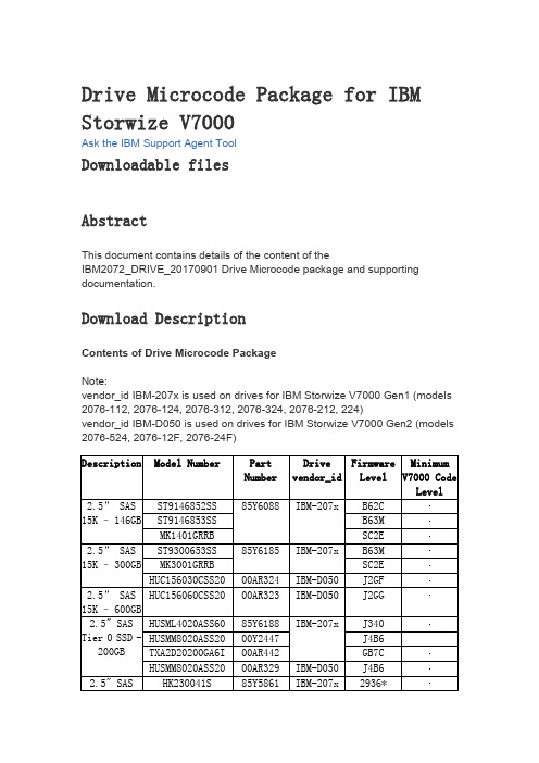
Drive Microcode Package for IBM Storwize V7000Ask the IBM Support Agent ToolDownloadable filesAbstractThis document contains details of the content of theIBM2072_DRIVE_20170901 Drive Microcode package and supporting documentation.Download DescriptionContents of Drive Microcode PackageNote:vendor_id IBM-207x is used on drives for IBM Storwize V7000 Gen1 (models 2076-112, 2076-124, 2076-312, 2076-324, 2076-212, 224)vendor_id IBM-D050 is used on drives for IBM Storwize V7000 Gen2 (models 2076-524, 2076-12F, 2076-24F)Level85Y5862v7.4.0.1 v6.3.0.04K BS** It is strongly recommended that customers with these drive model numbers (HUC106030CSS60, HUC106045CSS60, HUC106060CSS60) in their configuration, upgrade to this latest level of drive firmware.* If upgrading from 291E, please first upgrade to 2920 and then 2936. Please note: Ralston Peak 300 GB product_id=HUSML4030ASS60 is immune from this problem.2920 can be found on Fix Central in thispackage: StorageDisk-2076-DriveMicrocode-20121210Important Information:Drive Firmware upgrades are not supported on SAN Volume Controller or Storwize V7000 systems running V6.1 or V6.2. Please refer to the following Flash for more information.Drive Firmware Upgrades May Result in Temporary Loss of Host Access to Volumes on SAN Volume Controller and Storwize V7000Please refer to the svctask applydrivesoftware CLI command help in the IBM Storwize V7000 Information Center for installation instructions regarding this Drive Microcode Package.To check that your drive firmware is up to date download and run the Software Upgrade Test UtilityKeep Informed of UpdatesKeep up to date with the latest V7000 information by subscribing toreceive support notifications.Legal AgreementTHE FOLLOWING DOWNLOADS CONTAIN UPDATES AND FIXES TO CODE THAT WAS ORIGINALLY PROVIDED WITH THE IBM STORWIZEV7000 SOLUTION, INCLUDING THE IBM STORWIZE V7000 SOFTWARE. THE UPDATED CODE IS SUBJECT TO THE TERMS AND CONDITIONS OF THE LICENSE AGREEMENTS APPLICABLE TO THE CODE THAT IT UPDATES INCLUDING, AS APPROPRIATE, THE IBM AGREEMENT FOR MACHINE CODE AND IBM INTERNATIONAL PROGRAM LICENSE AGREEMENT. BY DOWNLOADING THE FOLLOWING FILES, YOU ARE AGREEING TO TREAT THE UPDATED CODE IN ACCORDANCE WITH THE APPLICABLE LICENSE AGREEMENTS.Download packageDESCRIPTION DOCUMENTATION LABEL DownloadOptionsPlatform IBMStorwize V7000Version IndependentEnglishByte Size 96217827Date 02 Sep 2017DriveMicrocodePackageHTTP。
针对卡慢盘、显示告警并隔离被注入故障的ssd和hdd磁盘的方法

针对卡慢盘、显示告警并隔离被注入故障的ssd和hdd磁盘的方法全文共四篇示例,供读者参考第一篇示例:针对卡慢盘、显示告警并隔离被注入故障的SSD和HDD磁盘的方法随着科技的不断发展,存储设备在各行各业中扮演着至关重要的角色。
SSD(固态硬盘)和HDD(硬盘驱动器)是两种主要的存储设备,它们在各自领域内都有着独特的优势。
正如任何其他设备一样,这些存储设备也可能会受到各种故障影响,导致卡慢盘或显示告警。
本文将讨论针对这些问题的方法,以及如何隔离被注入故障的SSD和HDD磁盘。
让我们来看看可能导致存储设备故障的原因。
一些常见的因素包括磁盘损坏、物理损坏、数据传输错误等。
当存储设备出现问题时,可能会导致卡慢盘和显示告警。
在这种情况下,我们需要采取适当的措施来解决问题。
针对卡慢盘问题,可以采取以下方法来解决:1. 清理存储空间:及时清理不必要的文件和数据,释放存储空间。
2. 升级固件:对SSD和HDD的固件进行升级,以修复可能存在的bug和问题。
3. 检查硬件连接:确保存储设备与计算机正确连接,避免连接不良导致的问题。
4. 检查系统设置:检查操作系统设置,确保存储设备能够正常工作。
1. 查看告警信息:及时查看存储设备的告警信息,了解问题所在。
2. 备份重要数据:在处理问题之前,务必备份重要数据,以免数据丢失。
3. 重启设备:尝试重启存储设备,有时可以解决一些问题。
4. 检查磁盘健康:使用专业的检测工具检查SSD和HDD的健康状况,及时发现问题并解决。
1. 使用安全软件:安装安全软件来防止外部恶意注入,保护存储设备安全。
2. 隔离感染设备:一旦发现磁盘被注入故障,立即隔离设备,不再使用。
3. 数据恢复:尝试使用专业的数据恢复工具来尝试恢复故障磁盘上的数据。
4. 更换磁盘:如果数据无法恢复或存储设备无法修复,那么需要更换新的磁盘。
针对卡慢盘、显示告警并隔离被注入故障的SSD和HDD磁盘,我们需要及时识别问题,并采取适当的方法来解决。
赛门铁克产品中文知识库文档列表

1. 赛门铁克产品中文知识库文档列表 (1)2. Symantec Endpoint Protection (SEP) 简体中文文档汇总(持续更新) (2)3. Symantec Endpoint Protection 11.0 主要文章 (8)4. NetBackup (NBU) 简体中文文档汇总(持续更新) (12)5. Backup Exec for Windows Servers (BEWS) 简体中文文档汇总(持续更新) (20)6. Backup Exec System Recovery (BESR) 简体中文文档汇总(持续更新) (30)7. Symantec Brightmail Gateway (SBG) 简体中文文档汇总(增加中) (34)8. Symantec Information Foundation 产品简体中文文档归总(持续更新) (35)9. Cluster Server (VCS) 简体中文文档汇总(持续更新) (38)10. Enterprise Vault (EV) 简体中文文档汇总(持续更新) (39)11. Storage Foundation (SF) 简体中文文档汇总(持续更新) (41)12. Volume Manager(VxVM)简体中文文档汇总(持续更新) (44)13. Volume Replicator (VVR) 简体中文文档汇总(持续更新) (45)1.赛门铁克产品中文知识库文档列表service1.symantec./SUPPORT/INTER/ent-securitysimplifiedchinesekb.nsf/cn_docid/本文档翻译自英文文档。
原英文文档可能在本翻译版发布后进行过修改更新。
赛门铁克对本翻译文档的准确度不做保证。
情形按照产品分类,将现有中文知识库文档汇总,以方便各位查阅。
解释Security (安全产品)•Symantec Endpoint Protection (SEP)•Symantec Brightmail Gateway (SBG)•Symantec Mail Security for SMTP (SMS)Availability (存储产品)•Symantec Backup Exec (BEWS)•Symantec Backup Exec System Recovery (BESR)•Symantec Cluster Server (VCS)•Symantec Enterprise Vault (EV)•Symantec NetBackup (NBU)•Storage Foundation (SF)•Symantec Volume Manager (VxVM)•Symantec Volume Replicator (VVR)•文档号:最近更新: 2009-12-02Date Created: 2009-10-15产品: All Products2.Symantec Endpoint Protection (SEP) 简体中文文档汇总(持续更新)本文档翻译自英文文档。
windows server * 无法安装驱动程序,此计算机上不存在英特尔(R),PRO适配器的解决方法

Windows Server2012启用Intel82579V网卡发布时间2012年8月8日,作者Ivo Beerens。
在安装Windows Server 2012的在我自制软件的服务器上,华硕P9X79主板板载Intel82579V千兆位NIC无法正常工作。
在华硕的网站,我发现了Windows 8的英特尔主板的驱动程序。
安装驱动程序后,网卡仍然不能正常工作。
为了获得英特尔82579V网卡工作在Windows Server2012上,我用了本次论坛主题为参考这篇博客文章。
下面是操作步骤:为了能够修改驱动程序,你需要运行下面的命令bcdedit -set loadoptions DISABLE_INTEGRITY_CHECKSbcdedit -set TESTSIGNING ON重新启动下载英特尔驱动程序。
我用的是英特尔驱动程序华硕为华硕P9X79主板将它们保存到一个地图,并提取它们,如果需要的话打开文件夹PRO1000打开文件夹Winx64打开文件夹NDIS63打开的e1c63x64.inf文件,我用记事本++编辑该文件,在[ControlFlags]节中删除3行①选择并复制[Intel.NTamd64.6.2.1] 中E1503行及以下部分②将复制的内容粘贴到[Intel.NTamd64.6.2]部分③修改后的e1c63x64.inf文件必须看起来像这样:保存文件安装Intel驱动程序完成安装后,英特尔82579V千兆网卡的识别和启用启用驱动程序的完整性检查,并禁止再次签署的测试,使用下面的命令:bcdedit -set loadoptions ENABLE_INTEGRITY_CHECKSbcdedit -set TESTSIGNING OFF重新启动现在,您可以在Windows Server2012使用Intel82579V千兆网卡了原文参考:http://www.ivobeerens.nl/2012/08/08/enable-the-intel-82579v-nic-in-windows-server-2012/ PS:如果你不知道怎么修改网卡驱动程序exe安装包中文件,可如下操作:用压缩软件,将网卡驱动程序(exe安装包)解压,按以上路径找到需要修改的文件用记事本打开,按图片中的标示进行修改(修改[Intel.NTamd*.*.*.*]时,不同的网卡驱动[Intel.NTamd******]中的行数可能不同,如果与图片中的不一致,可以看成将上一个[Intel.NTamd*.*.*.*]中多的行,复制到下面的[Intel.NTamd*.*.*]中去。
64位win8.1系统安装SAS9.4方法总结

1 / 17 目录64位win8.1系统安装SAS9.4方法总结 (2)1. 资源 (2)1.1 64位 (2)1.2 32位 (2)2. 电脑准备 (3)2.1 卸载以往所有版本 (3)2.2 磁盘空间 (3)2.3 英文用户文件夹名称 (3)3. 安装 (3)3.1 修改系统时间 (3)3.2 安装过程 (4)4. 更新SID (8)5. 新的更新SID (9)5.1 打开SAS (9)5.2 打开SID (9)5.3 运行 (10)5.4 关闭 (11)6. 问题 (11)6.1 一定存在的问题 (11)6.1.1 解决方法一 (12)6.1.2 解决方法二 (15)6.2 安装过程中可能出现的问题 (15)6.2.1 刚开始就挂掉了 (15)6.2.2 安装到最后一步出现“安装后处理失败” (16)7. 获取SID ................................................................................................................. 17 2 / 17 64位win8.1系统安装SAS9.4方法总结qxcr由于试验设计与数据统计分析课程及以后大家实验数据分析需要 以及老师提供的sas版本过于陈旧 需要改时间等 比较麻烦 个人通过网络搜索的信息及资源 实践安装了适用于64位windows 8.1及其以下系统的sas9.4 对相关过程及可能出现的问题及解决办法进行了一些总结 希望对大家的学习研究有所帮助。
个人能力有限 谢谢 1. 资源 1.1 64位64位SAS9.4安装程序压缩包及更新用的SID我共享在我的360云盘中 大家可以自行下载。
资源链接/cVky5QZUbwnkX 访问密码08cc总共16个分割的压缩包 约13.6G 全部下载后只需解压part01 会自动读取16个压缩包的。
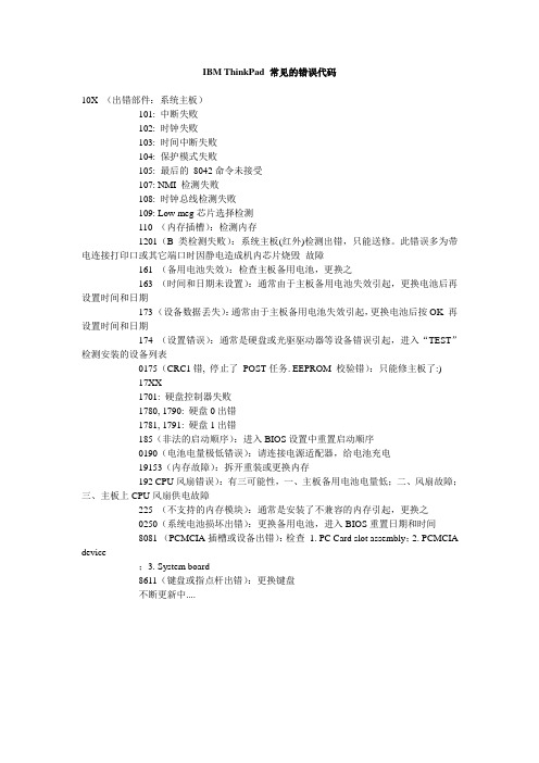
IBM ThinkPad 常见的错误代码
IBM ThinkPad 常见的错误代码10X (出错部件:系统主板)101: 中断失败102: 时钟失败103: 时间中断失败104: 保护模式失败105: 最后的8042命令未接受107: NMI 检测失败108: 时钟总线检测失败109: Low meg芯片选择检测110 (内存插槽):检测内存1201(B类检测失败):系统主板(红外)检测出错,只能送修。
此错误多为带电连接打印口或其它端口时因静电造成机内芯片烧毁故障161 (备用电池失效):检查主板备用电池,更换之163 (时间和日期未设置):通常由于主板备用电池失效引起,更换电池后再设置时间和日期173 (设备数据丢失):通常由于主板备用电池失效引起,更换电池后按OK 再设置时间和日期174 (设置错误):通常是硬盘或光驱驱动器等设备错误引起,进入“TEST”检测安装的设备列表0175(CRC1错, 停止了POST任务. EEPROM 校验错):只能修主板了:)17XX1701: 硬盘控制器失败1780, 1790: 硬盘0出错1781, 1791: 硬盘1出错185(非法的启动顺序):进入BIOS设置中重置启动顺序0190(电池电量极低错误):请连接电源适配器,给电池充电19153(内存故障):拆开重装或更换内存192 CPU风扇错误):有三可能性,一、主板备用电池电量低;二、风扇故障;三、主板上CPU风扇供电故障225 (不支持的内存模块):通常是安装了不兼容的内存引起,更换之0250(系统电池损坏出错):更换备用电池,进入BIOS重置日期和时间8081 (PCMCIA插槽或设备出错):检查1. PC Card slot assembly;2. PCMCIA device;3. System board8611(键盘或指点杆出错):更换键盘不断更新中....。
ThinkServer TS140 用户手册 V1.2
T品前请先阅读本手册
目录
声 明 ...................................................................................................................................................................................................................................3 商标和版权 ........................................................................................................................................................................................................................4 Safety Information(安全信息)....................................................................................................................................................................................5 第一章 产品简介 .......................................................................................................................................................................................................... 10 1.1 产品概述 ................................................................................................................................................................................................................... 10 1.2 产品特色 ................................................................................................................................................................................................................... 10
AS400常用命令集

显示AS/400的磁盘容量和使用状况:1.DSPSYSSTS “显示系统状态”2.显示用户简要表:DSPUSRPRF查看用户情况操作用户简要表:WRKUSRPRF创建新用户:CRTUSRPRF3.关机:GO POWER,选择3、F16直接关机;选择4、F16关机后重启动。
立即关机命令:PWRDWNSYS *IMMED4.查找命令GO CMD***5.使用系统请求菜单:shift +enter or alt +enter使用命令行显示:call qcmd使用系统助手:go assist使用信息助手:go info显示先前使用过的命令:call qcmd6.当前信息DSPMSG系统信息DSPMSG QSYSOPR7.控制线描述WRKLIND控制器描述WRKCTLD控制设备描述WRKDEVD配置设备状态WRKCFGSTS8.提交批处理作业SBMJOB +F4激活作业显示WRKACTJOB9.输出作业队列WRKOUTQ假脱机文件WRKSPLF10.打印机:菜单GO PRINTER WRKDEVD PRT0111.备份和恢复:恢复库RSTLIB恢复目标RSTOBJ备份目标SAVOBJ备份库SAVLIB12.磁带机的常用维护:初始化磁带机命令INZTAP磁带机常规检测及可靠性测试VFYTAP检查磁带机CHKTAP使用状态监控方法:服务工具——error log utility ——work with tape/disketle lifetime station13.发送消息SNDMSG参数*INQ表示该消息需要回复。
每个消息队列都有一个发送方式(delivery mode),描述消息队列收到消息时所做的动作和通知用户的方式。
*break中断用户的工作并显示接收到的消息。
*notify用消息警告灯和警铃声提醒用户收到消息。
*hold接收到消息时,不通知用户。
14.AS/400的网络属性:CHGNETA ——更改网络属性WRKHDWRSC ——显示400的通讯口及位置情况CRTLINSDLC ——创建线描述15.二、400中的集成文件系统:1.root(根)文件系统:支持目录结构和访问流文件的命令。
Aircrack-ng_for_Windows_教程

由于在Windows环境下不能如Linux环境般直接调用无线网卡,所以需要使用其他工具将无线网卡载入,以便攻击工具能够正常使用。
在无线攻击套装Aircrack-ng的Windows版本下内置了这样的工具,就是airserv-ng。
步骤1:打开CMD,通过cd命令进入到aircrack-ng for Windows版本所在目录,输入airserv-ng,可以看到如图5-29所示的内容。
图5-29 在CMD下运行airserv-ng参数解释:* -p,指定监听的端口,即提供连接服务的端口,默认为666;* -d,载入无线网卡设备,需要驱动支持;* -c,指定启动工作频道,一般设置为预攻击AP的工作频道,默认为1;* -v,调试级别设定。
作为Windows下的破解,第一步就是使用airserv-ng来载入我们当前使用的无线网卡,为后续破解做准备,命令如下(注意:在命令中出现的引号一律使用英文下的引号输入):airserv-ng -d "commview.dll|debug"或者airserv-ng -d "commview.dll| {my adapter id}"输入完成后airserv-ng会自动搜寻现有无线网卡,会有提示,选择正确的无线网卡直接输入y,此时airserv-ng就在正常载入驱动后,同时开始监听本地的666端口。
换句话说,airserv-ng提供的是该无线网卡的网络服务,其他计算机上的用户也可以连接到这个端口来使用这块网卡,如图5-30所示。
图5-30 airserv-ng工作中步骤2:现在可以使用airodump-ng来搜索当前无线环境了。
注意,要另开启一个CMD,再输入如下命令:airodump-ng 127.0.0.1:666这里在IP地址处输入为本机即127.0.0.1,端口采用的是默认的666。
图5-31 在CMD下运行airodump-ng如图5-31所示,当确定预攻击目标AP的频道后,使用组合键Ctrl + C中断,即可使用如下参数来精确定位目标:airodump-ng --channel number -w filename 127.0.0.1:666这里输入“airodump-ng --channel 7 -w onewpa 127.0.0.1:666”,回车后可看到如图5-32所示的内容图5-32 在CMD下运行airodump-ng进行抓包步骤3:现在,就可以和前面在BackTrack 2中讲述的一样进行Deauth攻击了,另开启一个CMD,输入(如图5-33所示):aireplay-ng -0 1 -a AP’s MAC 127.0.0.1:666参数解释参考前面对应章节。
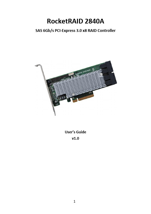
RocketRAID 2840A SAS 6Gb s PCI-Express 3.0 x8 RAID
RocketRAID 2840A SAS 6Gb/s PCI-Express 3.0 x8 RAID ControllerUser’s Guidev1.0Table of Contents1.HighPoint RocketRAID 2840A Overview (3)2.Board Layout & Hardware Installation (4)ing the RocketRAID 2840A (6)ing the RocketRAID Series HBA BIOS (6)3.1.1RocketRAID BIOS Setting Utility (6)3.1.2Using the BIOS Utility (7)3.1.3BIOS Commands (7)3.1.4Creating RAID Arrays (8)3.1.5Delete Arrays (12)3.1.6Add/Remove Spare Disks (12)3.1.7Settings (13)3.1.8View (14)3.2.Driver & WebGUI Installation (15)3.2.1Driver installation - Microsoft Windows (15)3.2.2Driver and WebGUI Installation (Linux or FreeBSD) . 163.3 Using the HighPoint WebGUI (16)4.Customer Support (16)1.HighPoint RocketRAID 2840A Overview RocketRAID 2800 series host bus adapters are the world’s most price competitive 6G SAS/SATA RAID controllers, and deliver unprecedentedend-to-end Generation 3.0 PCI Express transfer performance with Professional class RAID Storage reliability and management capabilities.RocketRAID 2800 series host bus adapters capitalize on HighPoint’s two decades of RAID and storage technology to deliver professional grade RAID storage at a fraction of the cost of conventional host RAID solutions. Each adapter is powered by our industry proven RAID technology, superior Gen 3.0 PCIe express transfer bandwidth, and up to sixteen dedicated 6Gb/s SAS channels, which support robust, high-performance RAID 0, 1, 5 6, 10, 50 and JBOD configurations of SAS or SATA hard drives of any disk format, including 512, 512e and 4Kn.Features and Specifications●8-lane, 8 GT/s PCI Express 3.0 Compliant●Four SFF-8643 mini-SAS HD ports●Support up to 16x SAS/SATA drives●Onboard LED Indicators and Alarm Buzzer●Multiple RAID Adapters supported●Online RAID Level Migration (ORLM)●Online Capacity Expansion (OCE)●RAID Quick Initialization for fast array setup●Disk Format compatible: 512, 512e, 4Kn●Larger than 2 TB Drive and RAID Array support●Disk media scan and repair●Device Error Recovery support●Automatic remap and fix drive bad block for RAID array●Spin down Massive Arrays of Idle Disks support●Staggered Drive Spin Up2.Board Layout & Hardware InstallationSFF-8643 connectorEach SFF-8643 connector supports 4 disk channels. Connect the hard disks or disk backplane to the RAID controller using the appropriate data cables.Active/FAIL LED PIN connector:LED pins are provided for Active/Fail status for each of the device channels.For more information about LED functionality and connection requirements, please refer to the document below:https:///lG3WBCwKGHT7yNuTsFCwXy0/HighPoint-Download/Document/Guide/RocketRAID/General%20Guide/LED_connection.pdfAlarm BuzzerAudible alarm will sound if a disk failed status occurs.I2C Pin ConnectorThe I2C Pin connector can be used to connect an enclosure device with I2C protocol for enclosure management.HPTLCD ConnectorConnector for the optional HPTLCD module.Hardware InstallationNote: Make sure the system is powered-off before installing the RAID Controller.1.Open the system chassis and locate an unused PCIe (x8, x16) slot.2.Remove the PCIe slot cover.3.Gently insert the RAID controller into the PCIe slot, and secure thebracket to the system chassis.4.After installing the adapter, attach the hard disks or disk backplaneto the RAID controller using the appropriate data cables.5.Close and secure the system chassis.ing the RocketRAID 2840Aing the RocketRAID Series HBA BIOS3.1.1RocketRAID BIOS Setting UtilityThe RocketRAID controller BIOS utility is an interface that provides management commands and controller related settings.After installing the RAID controller and powering on the system, the RAID controller BIOS should post during the system’s boot procedure.Use Ctrl + H key to log-in to the BIOS setting utility. The BIOS setting utility can be used for RAID management. The BIOS Utility will display information about hard drives attached to the adapter. Make sure all attached drives are detected by this utility. If any of the hard drives is not detected, power down the system and check the power and cable connections.Note: The following screenshots depict the RocketRAID 2840A BIOS utility. However, all RocketRAID models utilize the same interface.3.1.2Using the BIOS UtilityThe following keys are utilized by the RocketRAID BIOS utility:Arrow keys – Use these to move between different menu items.Enter – Open the selected toolbar command/execute the selected command. Esc – Move back to the previous menu, cancel the selected operation, or exit the BIOS Utility.3.1.3BIOS CommandsCreate: This command is used to open the RAID Creation menu. Delete: This command will delete the selected RAID array.Add/Remove Spare: This command is used to assign hard disks to function as spare disks. The controller is capable of using spare disks to automatically rebuild broken or faulted RAID arrays.Settings: This command opens the settings menu (To selecting the boot disk/array, staggered drive spin up etc.)View: This command is used to view hard disk and RAID information. Initialize: This command is used to prepare disks for use with RAID arrays.Disks must be initialized before they can be used to create arrays.3.1.4Creating RAID ArraysInitializing Disks:Before creating a RAID array, the disks must be initialized. Disk initialization writes necessary RAID configuration information to the hard disks. Select the Initialize command from the toolbar, and press the Enter key.Highlight the target disks using the arrow keys, and then press the Enter key. A numeral will be displayed before each selected disk. Once all target disks have been selected, press ESC key. The utility will display a warning, and ask you to press Y (yes) to initialize, or N (no) to cancel. Once initialized, these disks can be used to create RAID arrays. These disks will be displayed as “Initialized” (under Status).Warning: Initialization will destroy all pre- existing data on the selected hard disks. Only initialize disks that do not contain critical data.Create Arrays:Select Create from the toolbar and press the Enter key.e the arrow keys to select the RAID level and press the Enter key.e the arrow keys to highlight the Array Name option and pressthe Enter key. The array name dialogue box will appear. Use thekeyboard to input a new Array Name, and press the Enter key. Note: The Array Name command is optional – it is not necessary to name the array. The array can be named at a later time, and the name of the array can be changed at any time.3.On the Create menu, use the arrow keys to highlight the SelectDevices item and press the Enter key. A device list will appear, and display all available hard disk drives.4.Highlight the target disks that you want to use, and press the Enterkey to select them. A numeral will be displayed before eachselected disk. This number designates disk order. After all of thedisks have been selected and press the ESC key to return to theCreate Menu.5.Next, Use the↓arrow key to highlight the Capacity (GB) option andpress the Enter key. The total available capacity will be displayed.Press the Enter key if you wish to use all available space. If you wish to reserve disk space for additional arrays/single disks, use thekeyboard to input the amount of space (in GB) you wish to set aside for this particular array, and press the Enter key.Note: Multiple arrays can be created using the same set of hard disk drives. The Capacity option allows you to set aside disk space that be used to create another array, set as a spare disk, or partitioned to act asa single disk (by the operating system).6.For redundant RAID arrays (RAID 5, 50), select the Cache Policy:Write Back – Provides higher write performance for redundantRAID arrays. Data is at risk when there is a power failure, systemkernel panic and unresponsive abnormal conditions.Write Through – Writes directly to the disks (may reduce the risk of data loss during a critical failure, but at the cost of lowerperformance).7.Sector Size – Also known as “Variable Sector Size”. Use this option ifyou are using an older 32-bit Windows operating system. Thisallows older operating systems to support volumes over 2TB in size.Do not use if the operating system already supports large volumes (such as GPT).8.To complete the creation procedure, use the arrow key to highlightthe Start Creation item and press the Enter key.The Window will show 2 options when creating a RAID 5 array:Background Initialization and No initialization.Background initialization:The RAID array is accessible while disk initialization is beingperformed.A.This option will delete all content on the disks.B.The initialization time will be longer when compared to"Foreground" but the logical drives can be used during theinitialization process.No initialization:The No initialization option is recommended for use when rescuing an original array of for testing purposes. This option will not make any changes to the data area of each disk. When you select thisoption, a pop-up window will display; press Y (yes) to create thearray, or N (no) to cancel the creation process.3.1.5Delete ArraysHighlight the Delete command from the toolbar, and press the Enter key. The BIOS utility will display a list of available RAID arrays. Select the array you wish to delete, and press the Enter key.The utility will display a warning message. Press Y (yes) to delete the array, or select N (no) to cancel.Warning: All data stored on the array will be lost – do not delete if the array contains critical data.3.1.6Add/Remove Spare DisksThe Add/Remove Spare command is used to assign a hard disk to act as a Spare Disk. Spare Disks are used to automatically rebuild Redundant RAID arrays (RAID 1, 5, 10) in the case of disk failure. As with creating RAID arrays, disks must be initialized before they can be used as spares. To set a hard disk to act as a Spare Disk, use the arrow keys to select the target disk from the list of initialized disks, and press the Enter key. To remove the Spare Disk setting from a hard disk, highlight the spare disk, and press the Enter key. Generally, single disks are designated to act as spares (disks that are not configured into RAID arrays). However, in some instances, disks that are members of RAID arrays may also be designated to act as a spare. If the disks in question are part of a RAID array that did not utilize the full available capacity at the time of creation, these disks may be used as spares.3.1.7SettingsTo access the Settings menu, highlight the Settings command from the toolbar, and press the Enter key. There are Select Boot Device and Parameter Setting options in the menu.Select Boot Device:Select which disk or array will act as the boot disk, if the motherboard BIOS instructs the card to act as the boot device.▪When booting up the system, press CTRL + H during the HighPoint RocketRAID splash screen to enter the BIOS RAIDcreation utility.▪Navigate to Settings using arrow keys.▪Press Enter.▪Press Enter again.▪Select the desired RAID array.▪You will return to the main screen once the boot flag is setStaggered Spin up:The default value of this option is disabled. Enabling this setting will instruct the card to power up the hard disks, sequentially (one disk approximately every 2 seconds). Not all disk support this setting – consult the disk documentation for more information.3.1.8ViewThe View menu provides two options:Devices – This option will display information for each disk hosted by the HBA.RAID Array – This option will display information about each RAID array hosted by the HBA. Highlight the target device and press the Enter key to view details about the configuration.3.2.Driver & WebGUI Installation3.2.1Driver installation - Microsoft WindowsDownload and prepare the Windows Driver and WebGUI from the product download page.RocketRAID 2840A:/USA_new/series_rr2840a-Download.htm1.After installing the RAID controller, boot to the Windows operatingsystem.2.Windows should automatically detect the card as a new “RAIDController” under device manager.3.Right click the “RAID Controller” and select update/install thedriver.4.Select “Browse my computer for driver software”.5.Browse to the location of the driver and click “Next”.6.Reboot the system when prompted. The RocketRAID 2840Acontroller will be ready for use after Windows reboots.7.Extract the WebGUI package and double click the setup program toinstall.3.2.2Driver and WebGUI Installation (Linux or FreeBSD) Download and prepare the Driver and WebGUI from the product download page.RocketRAID 2840A:/USA_new/series_rr2840a-Download.htmRefer to the README file and Installation Guide under the software folder for the appropriate installation procedure.3.3 Using the HighPoint WebGUIPlease refer to the Online Help guide for more information about using the WebGUI:/help/4. Customer SupportIf you encounter any problems while utilizing the RocketRAID series HBA, or have any questions about this or any other HighPoint Technologies, Inc. product, feel free to contact our Customer Support Department.Web Support:/websupport/HighPoint Technologies, Inc. websites:。
Ghost克隆硬盘错误修复实例软件教程

第一步:用 KV3000 将三台电脑〔配置一样,分别设为电脑 A、电 脑 B、电脑 C〕的硬盘分区表信息全部去除。〔曾试图用 F10 功能
第2页 共4页
自动修复,但结果显示 Hard Disk Partition Table - OK!!!, 最终只好去除。〕详细方法见中国电脑教育报以前刊出的《一次用 KV3000 解除硬盘分区表故障的经验》一文。
第1页 共4页
5. 用 Fdisk 吩咐重建分区时,只能对 20%的硬盘容量〔原主 DOS 分区容量〕进展操作。此时,虽然扩展分区既不能删除也不能重 新建立,但却可以在其根底上接着建立逻辑分区。不过,明明扩 展分区有 15GB〔20GB 的硬盘〕,建立逻辑分区时却只有不到 10GB。
★分析:
凭我的经历,用 Fdisk 对硬盘正常进展分区后,不会有上述状况 出现。那么这些机子的问题又是如何产生的呢?后经反复考虑认 为可能性只有一个:这些硬盘都没有经过 Fdisk 的正常分区操作, 而是由硬盘对拷工具 Ghost 克隆出来的。因为目前硬盘的容量都 比拟大,装机人员为了省事,一般都采纳 Ghost 对硬盘进展克隆, 即先把一块硬盘用 Fdisk 分区,再用 Format 进展格式化,然后安 装操作系统,最终再用 Ghost 将整块硬盘镜像为一个.gho 文件刻 录到一张光盘上。在装机的时候,用 Ghost 程序把光盘上的.gho 文件克隆到目标盘上就可以了。
第3页 共4页
★结论:
1. 通过以上事实证明,用 Ghost 克隆整块硬盘时会导致硬盘分区 表错误。
2. 用 Ghost 软件快速初始化大容量硬盘〔参见《中国电脑教育报》 2003 年第 37 期 C10《用 Ghost 快速初始化大容量硬盘》〕不必须 是好事。外表看来的确是快速可行、省时省力,但假如想再分区 或因故进不了 Windows 系统而数据又在 E 盘以后的分区存放的话, 就会造成很大的麻烦。
linux常用的FAQ(GDLC support)-------基础操作中的FAQ。

EMB SYS ™中兴EMBSYS ™ CGS Linux V3.0 用户问答手册I随着越来越多的项目使用或准备使用NewStart CGS Linux 来进行电信级服务器Linux 的开发及应用开发,NewStart CGS Linux 的改进工作也在不断的推进。
学习和使用NewStart CGS Linux 当中,不时会有一些疑问,或者没有把握的地方,如果自己摸索,可能要花费很多的时间。
本文汇总了到目前为止常常被问起的问题,并做了回答,供大家速查。
本文档作为CGSL FAQ 的上游文档,用于收集FAQ 素材,以提供给文档开发人员,形成最终FAQ 。
1CGSL基本概念1.1CGSL系统的来源、与RedHat的关系、如何获取开源支持?关键字:来源,RedHat,支持版本:ALL分析与处理:问题:CGSL系统从何而来,与RedHat的关系有何关系,如何获取开源支持?解答:CGSL来源于开源社区,由开源社区的源代码构建,在提供CGSL版本的时候,参考了CentOS (对应于RHEL的开源版本)所用的内核版本号和相关软件包,并根据实际需要选取了他们所用的补丁集(毕竟红帽所用的方案是业界公认比较出色的)。
因此,CGSL与RHEL是高度兼容的。
除此之外,我们还对内核做了所需的改进,以及集成了相关的用户需求。
由于CGSL版本是自己根据开源软件包选择,增加或修改,相应的维护和问题解决,也都是我们自己进行的,RedHat对我们不提供支持,主要的支持来源为CGSL项目自身的研发团队和开源社区。
1.2CGSL版本号是怎样定义的?关键字:CGSL 版本号版本:ALL分析与处理:问题:CGSL系统的版本号是怎样定义的?解决:CGSL项目发布的基础版本和补丁版本命名遵从如下规则:版本命名规则中各字段的含义如下表所示:版本命名示例:1.3CGSL系统升级补丁的命名规则是怎样定义的?关键字:CGSL 版本号版本:ALL分析与处理:问题:CGSL系统升级补丁的命名规则是怎样定义的?解决:CGSL项目发布的系统升级补丁,其命名遵从如下规则:系统补丁命名规则中各字段的含义如下表所示:系统补丁命名示例:将32位V3.02.00基础版本升级至V3.02.00.P1补丁版本的系统升级补丁的名称为1.4怎样查看CGSL系统详细版本号?关键字:版本号版本:ALL分析与处理:CGSL系统中使用如下命令查看系统的详细版本号:执行结果如下所示:如上结果表示该系统的详细版本号为:CGSL V3.02.00版本。
- 1、下载文档前请自行甄别文档内容的完整性,平台不提供额外的编辑、内容补充、找答案等附加服务。
- 2、"仅部分预览"的文档,不可在线预览部分如存在完整性等问题,可反馈申请退款(可完整预览的文档不适用该条件!)。
- 3、如文档侵犯您的权益,请联系客服反馈,我们会尽快为您处理(人工客服工作时间:9:00-18:30)。
Comp6=eguidedsktp
Comp7=odbc
Comp8=ecobasic
Comp9=base
Comp10=pcfile
Comp11=graph
Comp12=connect
Comp13=eis
Comp14=af
Comp15=assist
PROC SETINIT RELEASE='9.2';
SITEINFO NAME='BRIDGETREE INC'
SITE=70021996 OSNAME='W32_WKS' RECREATE WARN=45 GRACE=45
BIRTHDAY='12AUG2009'D EXPIRE='30SEP2010'D PASSWORD=301288356;
[_SID_]
Version=9.2
Revision=9.2
Platform=Windows
Platform_long=Microsoft Windows Workstation 32-bit
Platform_short=win
Order=476195
Setnumid=70021996
CPU MODEL=' ' MODNUM=' ' SERIAL=' ' NAME=CPU000;
EXPIRE 'PRODNUM000' 'PRODNUM001' 'PRODNUM002' 'PRODNUM004'
'PRODNUM006' 'PRODNUM013' 'PRODNUM015' 'PRODNUM025' 'PRODNUM070'
*PRODNUM209 = ODBC SAS/ACCESS ODBC;
*PRODNUM215 = OLEDB SAS/ACCESS TO OLE DB;
*PRODNUM219 = TERADATABNDL SAS/ACCESS Teradata;
*PRODNUM538 = WKSPSRVLOCAL SAS Workspace Server for Local Access;
SID_schema=2
ph_agreement=PROMPT
SID_header=SAS 9.2
[_Info_]
[_FileData_]
$_Filename=setinit.sss
$_Path=sas\core\sasinst\
$_Date=
$_Time=
$_Stream=-------------------- BEGIN --------------------
[_EOF_]
Comp16=fsp
Comp17=stat
Comp18=oledb
$_Stream=--------------------- END ---------------------
$_Filename=tletter.txt
$_Path=.\
$_Date=
$_Time=
$_Stream=-------------------- BEGIN --------------------
Microsoft Windows Workstation 32-bit
Base SAS 30SEP2010
Enterprise Computing Offer 30SEP2010
SAS Enterprise Guide 30SEP2010
SAS/ACCESS Interface to ODBC 30SEP2010
*LICENSE=SAS 000000489419;
*0039161005 9.2;
*XYZ 436832;
$_Stream=--------------------- END ---------------------
$_Filename=compinfo.dat
$_Path=sas\core\sasinst\reserved\
'PRODNUM208' 'PRODNUM209' 'PRODNUM215' 'PRODNUM219' 'PRODNUM538'
'30SEP2010'D / CPU=CPU000;
SAVE; RUN;
*DROPPED SAS/CALC;
*DROPPED SAS/TUTOR CBT101;
*PRODNUM015 = CONNECT SAS/CONNECT;
*PRODNUM025 = EIS SAS/EIS;
*PRODNUM070 = MDDBCOM MDDB Server common products;
*PRODNUM208 = PCFILE SAS/ACCESS PC File Formats;
SAS/CONNECT 30SEP2010
SAS/EIS 30SEP2010
SAS/FSP 30SEP2010
SAS/GRAPH 30SEP2010
SAS/STAT 30SEP2010
$_Stream=--------------------- END ---------------------
SAS/ACCESS Interface to OLE DB 30SEP2010
SAS/ACCESS InterS/ACCESS Interface to Teradata 30SEP2010
SAS/AF 30SEP2010
SAS/ASSIST 30SEP2010
*PRODNUM000 = BASE Base SAS;
*PRODNUM001 = STAT SAS/STAT;
*PRODNUM002 = GRAPH SAS/GRAPH;
*PRODNUM004 = FSP SAS/FSP;
*PRODNUM006 = AF SAS/AF;
*PRODNUM013 = ASSIST SAS/ASSIST;
$_Date=
$_Time=
$_Stream=-------------------- BEGIN --------------------
[SeparatelylicensedComponents]
Comp1=sas
Comp2=teradatabndl
Comp3=accelmva
Comp4=teradata
