400MXY220M22X50中文资料
富士通 PRIMERGY CX2550 M2 雙處理器伺服器節點说明书
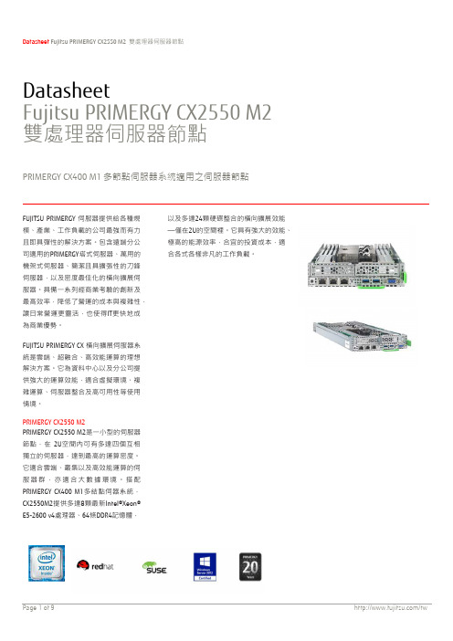
DatasheetFujitsu PRIMERGY CX2550 M2 雙處理器伺服器節點PRIMERGY CX400 M1多節點伺服器系統適用之伺服器節點FUJITSU PRIMERGY 伺服器提供給各種規模、產業、工作負載的公司最強而有力且即具彈性的解決方案。
包含遠端分公司適用的PRIMERGY塔式伺服器、萬用的機架式伺服器、簡潔且具擴張性的刀鋒伺服器,以及密度最佳化的橫向擴展伺服器。
具備一系列經商業考驗的創新及最高效率,降低了營運的成本與複雜性,讓日常營運更靈活,也使得IT更快地成為商業優勢。
FUJITSU PRIMERGY CX 橫向擴展伺服器系統是雲端、超融合、高效能運算的理想解決方案。
它為資料中心以及分公司提供強大的運算效能,適合虛擬環境、複雜運算、伺服器整合及高可用性等使用情境。
PRIMERGY CX2550 M2PRIMERGY CX2550 M2是一小型的伺服器節點,在2U空間內可有多達四個互相獨立的伺服器,達到最高的運算密度。
它適合雲端、叢集以及高效能運算的伺服器群,亦適合大數據環境。
搭配PRIMERGY CX400 M1多結點伺器系統,CX2550M2提供多達8顆最新Intel®Xeon® E5-2600 v4處理器、64條DDR4記憶體,以及多達24顆硬碟整合的橫向擴展效能—僅在2U的空間裡。
它具有強大的效能、極高的能源效率,合宜的投資成本,適合各式各樣非凡的工作負載。
高端HPC伺服器節點■四個PRIMERGY CX2550 M2伺服器節點,每個搭載兩個處理器■16條DDR4記憶體模組,以及多達6個本地儲存磁碟,一切僅需一個簡潔的2U機架式機箱。
■與同類標準機架式伺服器相比,使用的機架空間減少了50%。
更高的伺服器密度提高了每機架單位的性能。
■以4個簡潔型兩路伺服器為單位,做橫向擴展。
最新Intel®Xeon®處理器E5-2600 v4產品系列■可搭載兩顆Intel® Xeon® E5-2600 v4 處理器產品系列,每顆高達22核心、55MB的快取記憶體,進階的Turbo Boost 2.0技術、Hyper Threading,兩個加速的QPI連結以及內部記憶體管理模組。
施耐德产品型号说明
NS630N NS630N NS630H NS630N NS630N NS630H NS630N NS630H NS630H NS630N NS630H NS630L NS630N NS630L NS630L NS630H NS630L NS630L NS630H NS630L NS630L NS630L
NS630N NS630N NS630N
施耐德电气公司宣传培训部-施耐德介绍- 06/2000
2
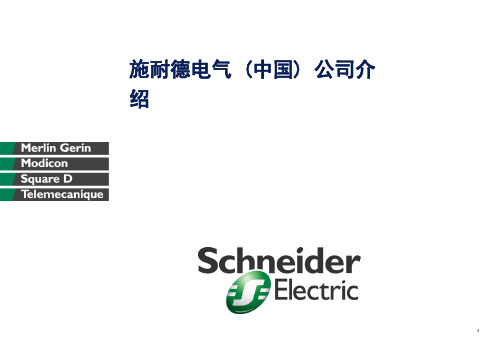
变压器与断路器配合选用推荐表(续)
变压器容量 并联数量 N*KVA 变压器 额定电流 In(A) 变压器 短路电 压 Ucc% 4 4 4 6 6 6 6 6 6 6 6 6 6 6 6 6 6 6 6 6 6 6 进线 短路电流 KA 进线断路器 最小分断能力 KA 进线断路 器型号 出线 短路电流 KA 出线断路器 型号 〈 =100A NS100N NS100H NS100H NS100N NS100H NS100H NS100N NS100H NS630H NS100H NS100H NS100L NS100H NS100L NS100L NS100H NS100L NS100L NS100H NS100L NS100L NS100L 160A 250A 400A 630A
Lcs=75%Lcu;
框架电流 08:800A 10:1000A 12:1250A 16:1600A 20:2000A
可由客户自已加装的附件: 辅助开关(OF)选件 门框(CDP) 瞬动欠压脱扣器(MN)
说明:
断路器的额定值与框架电流等级相同 MCH,MX/XF电压等级有AC200V及AC380V两种选择 (MX与XF必须选择相同的电压等级)
12
Masterpact D 空气断路器选型表 MD16-2
MPXM2202GS;MPXM2202AS;MPXM2202A;MPX2202DP;MPX2202GP;中文规格书,Datasheet资料

•
•
MPAK Package (MPXM2202 Series)
MPXM2202D
1320
•
•
MPXM2202DT1
1320
•
•
MPXM2202A
1320
•
MPXM2202GS
1320A
•
•
MPXM2202GST1
1320A
•
•
MPXM2202AS
1320A
•
Absolute
• •
• •
Device Marking
3. Full Scale Span (VFSS) is defined as the algebraic difference between the output voltage at full rated pressure and the output voltage at the minimum rated pressure.
—
—
± 0.1
—
%VFSS
Temperature Hysteresis(5) (-40°C to +125°C)
—
—
± 0.5
—
%VFSS
Temperature Effect on Full Scale Span(5)
TCVFSS
-2.0
—
2.0
%VFSS
Temperature Effect on Offset(5)
MPX2202DP CASE 344C-01
MPX2202ASX CASE 344F-01
SMALL OUTLINE PACKAGES
MPAK
MPXV2202GP CASE 1351-01
S2M中文规格书

To learn more about ON Semiconductor, please visit our website atPlease note: As part of the Fairchild Semiconductor integration, some of the Fairchild orderable part numbers will need to change in order to meet ON Semiconductor’s system requirements. Since the ON Semiconductor product management systems do not have the ability to manage part nomenclature that utilizes an underscore (_), the underscore (_) in the Fairchild part numbers will be changed to a dash (-). This document may contain device numbers with an underscore (_). Please check the ON Semiconductor website to verify the updated device numbers. The most current and up-to-date ordering information can befound at . Please email any questions regarding the system integration to Fairchild_questions@.ON Semiconductor and the ON Semiconductor logo are trademarks of Semiconductor Components Industries, LLC dba ON Semiconductor or its subsidiaries in the United States and/or other countries. ON Semiconductor owns the rights to a number of patents, trademarks, copyrights, trade secrets, and other intellectual property. A listing of ON Semiconductor’s product/patent coverage may be accessed at /site/pdf/Patent-Marking.pdf. ON Semiconductor reserves the right to make changeswithout further notice to any products herein. ON Semiconductor makes no warranty, representation or guarantee regarding the suitability of its products for any particular purpose, nor does ON Semiconductor assume any liability arising out of theapplication or use of any product or circuit, and specifically disclaims any and all liability, including without limitation special, consequential or incidental damages. Buyer is responsible for its products and applications using ON Semiconductor products, including compliance with all laws, regulations and safety requirements or standards, regardless of any support or applications information provided by ON Semiconductor. “Typical” parameters which may be provided in ON Semiconductor data sheets and/or specifications can and do vary in different applications and actual performance may vary over time. All operating parameters, including “Typicals” must be validated for each customer application by customer’s technical experts. ON Semiconductor does not convey any license under its patent rights nor the rights of others. ON Semiconductor products are not designed, intended, or authorized for use as a critical component in life support systems or any FDA Class 3 medical devices or medical devices with a same or similar classification in a foreign jurisdiction or any devices intended for implantation in the human body. Should Buyer purchase or use ON Semiconductor products for any such unintended or unauthorized application, Buyer shall indemnify and hold ON Semiconductor and its officers, employees, subsidiaries, affiliates, and distributors harmless against all claims, costs, damages, and expenses, and reasonable attorney fees arising out of, directly or indirectly, any claim of personal injury or death associatedS2A - S2M — General-Purpose Rectifiers (Glass Passivated)S2A - S2MGeneral-Purpose Rectifiers (Glass Passivated)Features•High-Current Capability, 2 A Rated•Fast Response: 2 μs T rr•Low-Forward Voltage Drop, 1.15 V V F Max at 2 A•High-Surge Current Capability, 50 A 2s I FSM•Glass Passivated Junction•RoHS Compliant•UL Certified, UL #E258596Applications•Power Supplies•AC to DC Rectification•Bypass Diodes Ordering InformationPart NumberMarking Package Packing Method S2AS2A DO-214AA (SMB)Tape and ReelS2BS2B S2DS2D S2GS2G S2JS2J S2KS2K S2M S2M Description The S2 family of devices are general-purpose 2 A rated rectifiers with voltage ratings ranging from 50 to 1000 V.They are implemented in traditional SMB packages and are well known to the industry. For advanced or special requirements, please contact a Fairchild Semiconductor representative.SMB/DO-214AA COLOR BAND DENOTES CATHODE2.202.504.70 2.65MAX2.451.90B 0.2030.0500.300.052.15 1.65A0.13M C B AC 3.953.30B2.201.91B5.605.08B4.754.050.13M C B ABA0.410.151.600.75R0.15 4X8°0°0.450-8°DETAIL ASCALE 20 : 1LAND PATTERN RECOMMENDATIONGAUGEPLANENOTES:A.EXCEPT WHERE NOTED CONFORMS TOJEDEC DO214 VARIATION AA.B DOES NOT COMPLY JEDEC STD. VALUE.C.ALL DIMENSIONS ARE IN MILLIMETERS.D.DIMENSIONS ARE EXCLUSIVE OF BURRS,MOLD FLASH AND TIE BAR PROTRUSIONS.E.DIMENSION AND TOLERANCE AS PER ASMEY14.5-1994.ND PATTERN STD. DIOM5336X240M.G.DRAWING FILE NAME: DO214AAREV1S2A - S2M — General-Purpose Rectifiers (Glass Passivated) Figure 6. 2-LEAD, SMB, JEDEC DO-214, VARIATION AA。
威盛WM8650中文说明书V0.3(7寸)

资料来源:爱购机目录................................................................................................... 错误!未定义书签。
1 外观描述 (2)2 电源键的用法 (3)3 触摸屏 (4)4转接盒 (4)5 SD卡的使用 (5)6开始使用 (5)给设备充电 (5)启动设备 (5)Wi-Fi 网络设置 (5)7桌面 (5)8锁屏界面 (6)9预装程序 (7)10桌面菜单功能 (8)11 程序管理 (10)安装程序 (10)直接从网络上下载程序 (10)卸载程序 (10)12 天气 (10)13 时钟 (11)闹钟 (11)14在线软件安装 (12)菜单功能 (12)15浏览器 (13)16 日历 (13)新建活动 (13)17 相机 (13)拍摄图片 (13)录制视频 (14)18 计算器 (14)19 电子邮件 (14)添加邮件账户 (14)收件箱 (15)编辑邮件账户 (15)删除邮件账户 (16)20 文件浏览器 (16)在电脑和设备之间拷贝文件 (17)删除文件 (17)21 我的音乐 (17)播放音乐 (17)对音乐盒播放列表进行操作 (18)22 我的视频 (18)播放视频 (18)对视频和播放列表进行操作 (19)23 我的相册 (19)涂鸦 (20)24 通讯录 (20)添加新的联系人 (20)添加联系人到收藏 (20)编辑联系人 (20)删除联系人 (20)25 图片截取 (21)26 程序管理器 (21)停止程序 (21)卸载程序 (21)27 YouTube (21)28 土豆视频 (22)29 Wi-Fi设置 (22)30 3G Settings (22)31 连接ADSL上网 (23)32 有线网络 (23)33 设置 (23)常见问题 (25)电池管理 (26)电池充电 (26)重要安全提示 (26)附录.建议可选配件及型号 (27)1 外观描述前视图:右视图:左视图:顶视图:2 电源键的用法开机: 长按电源键2秒。
WDZ-400EX概述V2.2
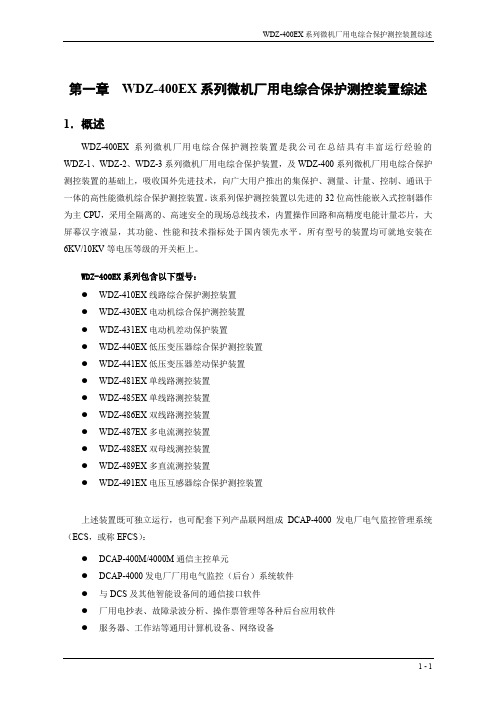
第一章WDZ-400EX系列微机厂用电综合保护测控装置综述1.概述WDZ-400EX系列微机厂用电综合保护测控装置是我公司在总结具有丰富运行经验的WDZ-1、WDZ-2、WDZ-3系列微机厂用电综合保护装置,及WDZ-400系列微机厂用电综合保护测控装置的基础上,吸收国外先进技术,向广大用户推出的集保护、测量、计量、控制、通讯于一体的高性能微机综合保护测控装置。
该系列保护测控装置以先进的32位高性能嵌入式控制器作为主CPU,采用全隔离的、高速安全的现场总线技术,内置操作回路和高精度电能计量芯片,大屏幕汉字液显,其功能、性能和技术指标处于国内领先水平。
所有型号的装置均可就地安装在6KV/10KV等电压等级的开关柜上。
WDZ-400EX系列包含以下型号:●WDZ-410EX线路综合保护测控装置●WDZ-430EX电动机综合保护测控装置●WDZ-431EX电动机差动保护装置●WDZ-440EX低压变压器综合保护测控装置●WDZ-441EX低压变压器差动保护装置●WDZ-481EX单线路测控装置●WDZ-485EX单线路测控装置●WDZ-486EX双线路测控装置●WDZ-487EX多电流测控装置●WDZ-488EX双母线测控装置●WDZ-489EX多直流测控装置●WDZ-491EX电压互感器综合保护测控装置上述装置既可独立运行,也可配套下列产品联网组成DCAP-4000发电厂电气监控管理系统(ECS,或称EFCS):●DCAP-400M/4000M通信主控单元●DCAP-4000发电厂厂用电气监控(后台)系统软件●与DCS及其他智能设备间的通信接口软件●厂用电抄表、故障录波分析、操作票管理等各种后台应用软件●服务器、工作站等通用计算机设备、网络设备DCAP-4000发电厂电气监控管理系统的结构如图1.1所示,系统的详情请参见《DCAP-4000发电厂电气监控管理系统技术说明书》。
LPC系列保护测控 #1机 400V工作段WDZ-400系列保护测控6kV厂用2B6kV厂用2A 柴油机组直流微机励磁发变组保护同期录波UPS 等#1机组其它智能设备快切高备变保护柴油机组直流 LPC系列保护测控WDZ-400系列保护测控其它公用智能设备6kV公用01B 6kV公用01A WDZ-400系列保护测控微机励磁发变组保护同期录波UPS 6kV厂用1B6kV厂用1A 等#2机组其它智能设备#2机 400V工作段图1.1 DCAP-4000发电厂电气监控管理系统(ECS )结构示意图2.特点WDZ-400EX 系列微机厂用电综合保护测控装置具有以下显著特点:● 基于分层分布式电气监控管理系统的设计思想,一个元件(一个间隔)对应一个装置,各间隔功能独立,各装置之间通过网络联结,网络组态灵活,使整个系统的可靠性得到很大提高,任一装置故障不影响其他装置和系统的正常工作。
德兰特XPLORER400电源质量分析仪说明书

XvG UIDEX PLORER400 SPX PLORER400POWER QUALITY ANALYZERTake Dranetz PQ Monitoring to the Air or Seawith 400Hz Capability!Dranetz HDPQ® Xplorer 400 SPIP65 Enclosure - No DisplayDranetz HDPQ® Xplorer 4007” Color, Touch DisplayMADE IN USAX PLORER400 SPX PLORER400®M02-RevA(4) Differential Voltage: 512 s/c, 64s/c @400Hz, 16 bit resolution0-1000Vrms, AC/DC, ±0.1 % reading, <40V ±0.5%FSI EC 61000-4-30 Class A: 60-1000Vrms, ±0.1 % of Udin, range of(4) Current (rms): 512 s/c, 16 bit resolutionR ange probe dep., AC/DC, +/- 0.1% reading+/- 0.05% FS,T ransients - High Speed: 1MHz, Range probe dep., 10% ofReading, +/- 0.5%FSFrequency:42.5-69Hz +/- 0.01Hz, 380-420Hz +/- 0.1 HzPower/Energy - 1 Second samplingReal Power (W) - P: meets 0.2S requirements, range probe dep.Apparent Power (VA) - S: meets 0.2S requirements, range probe dep.Reactive Power (var) - Q: meets 0.2S requirements, range probe dep.Power Factor (W/VA) -”true” -1 to 0 to +1Displacement PF -1 to 0 to +1Demand (in W): meets 0.2S requirements, range probe dep.Energy (in Wh): meets 0.2S requirements, range probe dep.Distortion - 200ms, 3 sec, 10 min windowsVthd: 0-100%, +/- 5% for V>=10% Vnom,V Ind Harm: DC, 2-127, @50/60 Hz, 2-15 @400Hz, +/- 5% for V>=10% VnomIthd: 0-100%, +/- 5% for I>=10% Inom,I Ind Harm: DC, 2-63 @50/60 Hz, 2-15 @400 Hz, +/- 5% for I>=10% InomMisc.Pst - 10 minutes: 0.2-10, +/- 0.05 @ Pst=1 (50/60 Hz only)Plt - 2 hours: 0.2-10, +/- 0.05 @ Pst=1 (50/60 Hz only)Automatic SetupsPre-programmed monitoring modesAnswerModules®- Sag/Dip Directivity, PF Cap, MotorDashboards - PQ, Demand & EnergySimultaneous PQ, Demand & EnergyMini ReportPower QualityIEC 61000-4-30 Class A: Edition 2 (2008)IEEE 1159: 2009PowerIEEE 1459: 2000HarmonicsIEC 61000-4-7 Class 1: Edition 2 (2008)IEEE 519: 2014Voltage FlickerIEC 61000-4-15: Edition 2 (2010)IEEE 1453: 2011Compliance/TestingEN 50160: 2010GENERAL SPECIFICATIONSDranetz HDPQ Xplorer 400Size: (10”w x 8”h x 2.75”d) (25.4cm x 20.3cm x 7.00cm)Weight: 4.2lbs, 2kgOperating temperature: 0 to 50 deg C (32 to 122 deg F)Storage temperature: -20 to 55 deg C (-4 to 131 deg F)Humidity: 10-90% non condensing2.5 hours run time on full charge, 3 hours charge timeDranetz HDPQ Xplorer 400 SP (IP65 Enclosure)Size: (11”w x 6.5”h x 2.5”d), (27.9cm x 16.5cm x 6.4cm)Weight: 3.2lbs, 1.45kgOperating temperature: -10 to 50 deg C (14 to 122 deg F)Storage temperature: -40 to 85 deg C (-40 to 185 deg F)Humidity: 10-90% non condensing30 minutes run time on full charge, 3 hours charge timeClock accuracy and resolutionInternal: +/- 1 sec/day at 25deg CNTP: +/-10 msecGPS: +/-1 msecAC Adapter: 90-264(max) 50/60HzMemory size: 4GBDisplay: 7” WVGA color graphic, Icon based touch LCD, LED Backlit(Xplorer 400 only)Languages: English, German, Spanish, French, Italian, Swedish, Finnish,Polish, Chinese (traditional and simplified), Thai, KoreanCOMMUNICATIONSEthernet, 802.11 b/g/n WirelessUSB On The Go (OTG)Bluetooth via USB adapterVNC remote controlAndroid® & Apple® AppPrinted in the United States. Specifications are subject to change without notice.Applications –50Hz, 60Hz & 400Hz Capabilities!The Dranetz HDPQ Xplorer 400 family takes PQ, Demand and Energy monitoring to new heights by adding 400Hz monitoring capabilities to the already powerful Dranetz HDPQ Xplorer. Ap-Demand & Energy TrendDranetz HDPQ Live VNC & DownloadDranetz HDPQ Xplorer 400Portable with 7” Display。
电子元器件芯片AD4004BRMZ中文规格书
AD4000/AD4004/AD4008Data Sheet Rev. E | Page 2 of 40TABLE OF CONTENTSFeatures (1)Applications (1)Functional Block Diagram (1)General Description (1)Revision History (2)Specifications (5)Timing Specifications (8)Absolute Maximum Ratings (10)Thermal Resistance (10)ESD Caution (10)Pin Configurations and Function Descriptions (11)Typical Performance Characteristics (12)Terminology (18)Theory of Operation (19)Circuit Information (19)Converter Operation (20)Transfer Functions (20)Applications Information (21)Typical Application Diagrams (21)Analog Inputs .............................................................................. 22 Driver Amplifier Choice ........................................................... 23 Ease of Drive Features ............................................................... 24 Voltage Reference Input ............................................................ 25 Power Supply ............................................................................... 25 Digital Interface .......................................................................... 25 Register Read/Write Functionality........................................... 28 Status Bits .................................................................................... 30 CS Mode, 3-Wire Turbo Mode ................................................. 31 CS Mode, 3-Wire Without Busy Indicator ............................. 32 CS Mode, 3-Wire with Busy Indicator .................................... 33 CS Mode, 4-Wire Turbo Mode ................................................. 34 CS Mode, 4-Wire Without Busy Indicator ............................. 35 CS Mode, 4-Wire with Busy Indicator .................................... 36 Daisy-Chain Mode ..................................................................... 37 Layout Guidelines....................................................................... 38 Evaluating the AD4000/AD4004/AD4008 Performance ...... 38 Outline Dimensions ....................................................................... 39 Ordering Guide .......................................................................... 40 REVISION HISTORY2/2021—Rev. D to Rev. EChanges to Features Section, Applications Section, GeneralDescription Section (1)Changes to Specifications Section and Table 1 (5)Changes to Timing Specifications Section (8)Added Note 1 to Table 2; Renumbered Sequentially ................... 8 Deleted Timing Diagram Section and Figure 3; RenumberedSequentially (8)Added Note 1 to Table 3; Renumbered Sequentially (9)Changes to Thermal Resistance Section (10)Changes to Table 7 (11)Changes to Effective Number of Bits (ENOB) Section (18)Changes to Figure 7 Caption and Figure 10 Caption (12)Changes to Figure 11 and Figure 14 (12)Changes to Circuit Information Section and Table 8 (19)Changes to Typical Application Diagrams Section .................... 21 Changes to Input Overvoltage Clamp Circuit Section .............. 22 Changes to Table 10, Driver Amplifier Choice Section, andHigh Frequency Input Signals Section ........................................ 23 Changes to Multiplexed Applications Section, Input SpanCompression Section, and High-Z Mode Section ..................... 24 Changes to Figure 44 Caption, Figure 45 Caption, Voltage Reference Input Section, and Digital Interface Section ............ 25 Changes to Register Read/Write Functionality Section and Figure 46 .......................................................................................... 28 Changes to Figure 47 ...................................................................... 29 Changes to Status Bit Section and Figure 49 .............................. 30 Changes to CS Mode, 3-Wire Turbo Mode Section .................. 31 Changes to CS Mode, 3-Wire Without Busy Indicator Section ...... 32 Changes to CS Mode, 3-Wire With Busy Indicator Section, Figure 54, and Figure 55 ................................................................ 33 Changes to CS Mode, 4-Wire Turbo Mode Section .................. 34 Changes to CS Mode, 4-Wire Without Busy Indicator Section ...... 35 Changes to CS Mode, 4-Wire with Busy Indicator Section and Figure 61 .......................................................................................... 36 Changes to Daisy-Chain Mode Section and Figure 62 ............. 37 Changes to Layout Guidelines and Evaluating the AD4000/AD4004/AD4008 Performance Section ............................. 38 Updated Outline Dimensions................................................................ 39 Changes to Ordering Guide . (40)Data SheetAD4000/AD4004/AD4008Rev. E | Page 3 of 408/2019—Rev. C to Rev. DAdded Figure 2; Renumbered Sequentially (1)Changes to Features Section and General Description Section (1)Added Figure 18 and Figure 21 (13)Added Figure 27, Figure 28, and Figure 29 (14)Added Figure 33 and Figure 35 (15)Changes to Figure 31 and Figure 32 (15)Changes to Figure 38 (18)Changes to Input Overvoltage Clamp Circuit Section (21)Changes to High-Z Mode Section, Figure 45, and Figure 46 .... 23 Added Configuration Register Details Section and Serial ClockFrequency Requirements Section (24)Changes to Digital Interface Section (24)Deleted Table 12 and Table 13; Renumbered Sequentially (25)Added Table 12 and Table 13; Renumbered Sequentially .......... 25 Changes to Register Read/Write Functionality Section andFigure 47 (26)Changes to Figure 48 (27)Added Table 58 ................................................................................ 28 Changes to Status Bits Section ....................................................... 28 Changes to CS Mode, 3-Wire Turbo Mode Section andFigure 51 ........................................................................................... 29 Changes to CS Mode, 3-Wire Without Busy Indicator Sectionand Figure 53 ................................................................................... 30 Changes to CS Mode, 3-Wire with Busy Indicator Section andFigure 55 ........................................................................................... 31 Changes to CS Mode, 4-Wire Turbo Mode Section andFigure 57 ........................................................................................... 32 Changes to CS Mode, 4-Wire Without Busy Indicator Sectionand Figure 59 ................................................................................... 33 Changes to CS Mode, 4-Wire with Busy Indicator Section andFigure 61 (34)Changes to Daisy-Chain Mode Section and Figure 64 (35)Updated Outline Dimensions (37)Changes to Ordering Guide ........................................................... 38 10/2017—Rev. B to Rev. CChanges to Features Section (1)Added Multiplexed Applications Section (21)Changes to Ordering Guide (36)Added Timing Diagram Section (8)Moved Figure 3 .................................................................................. 8 9/2017—Rev. A to Rev. BAdded AD4008 ................................................................... Universal Changes to Title, Features Section, General Description Section,and Figure 1 (1)Changes to Table 1 (4)Changes to Timing Specifications Section and Table 2 (7)Changes to Table 4 (8)Changes to Table 5 ............................................................................ 9 Changes to Typical Performance Characteristics Section Layout .. 11 Changes to Figure 19 ............................................................................... 13 Added Figure 25; Renumbered Sequentially ............................... 14 Changes to Figure 28 ...................................................................... 14 Change to Zero Error Definition, Terminology Section ........... 16 Changes to Circuit Information Section and Table 8 ................. 17 Changes to Converter Operation Section and Note 1 and Note 2, Table 9 ................................................................................. 18 Changes to High Frequency Input Signals Section, Figure 36 Caption, and Figure 37 Caption .................................................... 21 Added Figure 38 .............................................................................. 21 Changes to Input Span Compression Section, High-Z Mode Section, Figure 40, and Figure 41 Caption................................... 22 Changes to Figure 42 Caption, Figure 43 Caption, Power Supply Section, and Figure 44 Caption ..................................................... 23 Changes to Figure 45, Digital Interface Section, and Table 11 ........ 24 Changes to Register Read/Write Functionality Section and Figure 46 Caption ............................................................................ 25 Changes to CS Mode, 3-Wire Turbo Mode Section ................... 28 Changes to CS Mode, 3-Wire with Busy Indicator Section ...... 30 Changes to CS Mode, 4-Wire Turbo Mode Section ................... 31 Changes to CS Mode, 4-Wire with Busy Indicator Section ...... 33 Changes to Daisy-Chain Mode Section ....................................... 34 Changed Evaluating the AD4000/AD4004 Performance Section to Evaluating the AD4000/AD4004/AD4008 Performance Section .............................................................................................. 35 Changes to Evaluating the AD4000/AD4004/AD4008 Performance Section ....................................................................... 35 Changes to Ordering Guide ........................................................... 36 4/2017—Rev. 0 to Rev. A Added AD4004 ................................................................... Universal Changes to Title, Features Section, General Description Section, and Figure 1 ....................................................................................... 1 Changes to Table 1 ............................................................................ 3 Changes to Table 2 ............................................................................ 6 Changes to Table 4 ............................................................................ 7 Changes to Table 7 ............................................................................ 9 Changes to Figure 19 and Figure 21 ............................................. 12 Changes to Figure 24 ...................................................................... 13 Added Figure 25; Renumbered Sequentially ............................... 13 Moved Terminology Section ......................................................... 15 Changes to Circuit Information Section and Table 8 ................. 16 Changes to Figure 33 ...................................................................... 18 Changes to RC Filters Section ....................................................... 19 Changes to High Frequency Input Signals Section .................... 20 Changes to High-Z Mode Section, Figure 38, and Figure 39 .... 21 Changes to Long Acquisition Phase Section and Figure 43 ...... 22 Changes to Digital Interface Section and Register Read/Write Functionality Section . (23)Changes to Figure 45 (24)。
易用Logic PM2220电力表说明书
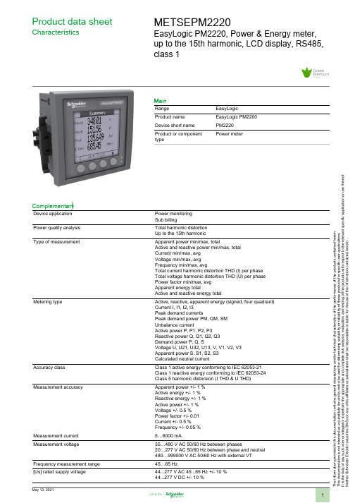
T h e i n f o r m a t i o n p r o v i d e d i n t h i s d o c u m e n t a t i o n c o n t a i n s g e n e r a l d e s c r i p t i o n s a n d /o r t e c h n i c a l c h a r a c t e r i s t i c s o f t h e p e r f o r m a n c e o f t h e p r o d u c t s c o n t a i n e d h e r e i n .T h i s d o c u m e n t a t i o n i s n o t i n t e n d e d a s a s u b s t i t u t e f o r a n d i s n o t t o b e u s e d f o r d e t e r m i n i n g s u i t a b i l i t y o r r e l i a b i l i t y o f t h e s e p r o d u c t s f o r s p e c i f i c u s e r a p p l i c a t i o n s .I t i s t h e d u t y o f a n y s u c h u s e r o r i n t e g r a t o r t o p e r f o r m t h e a p p r o p r i a t e a n d c o m p l e t e r i s k a n a l y s i s , e v a l u a t i o n a n d t e s t i n g o f t h e p r o d u c t s w i t h r e s p e c t t o t h e r e l e v a n t s p e c i f i c a p p l i c a t i o n o r u s e t h e r e o f .N e i t h e r S c h n e i d e r E l e c t r i c I n d u s t r i e s S A S n o r a n y o f i t s a f f i l i a t e s o r s u b s i d i a r i e s s h a l l b e r e s p o n s i b l e o r l i a b l e f o r m i s u s e o f t h e i n f o r m a t i o n c o n t a i n e d h e r e i n .Product data sheetCharacteristicsMETSEPM2220EasyLogic PM2220, Power & Energy meter,up to the 15th harmonic, LCD display, RS485,class 1MainRange EasyLogic Product name EasyLogic PM2200Device short name PM2220Product or component typePower meterComplementaryDevice application Power monitoring Sub billingPower quality analysis Total harmonic distortion Up to the 15th harmonicType of measurementApparent power min/max, totalActive and reactive power min/max, total Current min/max, avg Voltage min/max, avg Frequency min/max, avgTotal current harmonic distortion THD (I) per phase Total voltage harmonic distortion THD (U) per phase Power factor min/max, avg Apparent energy totalActive and reactive energy totalMetering typeActive, reactive, apparent energy (signed, four quadrant)Current I, I1, I2, I3Peak demand currentsPeak demand power PM, QM, SM Unbalance currentActive power P, P1, P2, P3Reactive power Q, Q1, Q2, Q3Demand power P, Q, SVoltage U, U21, U32, U13, V, V1, V2, V3Apparent power S, S1, S2, S3Calculated neutral currentAccuracy classClass 1 active energy conforming to IEC 62053-21Class 1 reactive energy conforming to IEC 62053-24Class 5 harmonic distorsion (I THD & U THD)Measurement accuracyApparent power +/- 1 %Active energy +/- 1 %Reactive energy +/- 1 %Active power +/- 1 %Voltage +/- 0.5 %Power factor +/- 0.01Current +/- 0.5 %Frequency +/- 0.05 %Measurement current 5…6000 mAMeasurement voltage35…480 V AC 50/60 Hz between phases20…277 V AC 50/60 Hz between phase and neutral 480…999000 V AC 50/60 Hz with external VT Frequency measurement range 45…65 Hz[Us] rated supply voltage44...277 V AC 45...65 Hz +/- 10 %44...277 V DC +/- 10 %Network frequency50 Hz60 HzRide-through time100 Ms 120 V AC typical400 Ms 230 V AC typical50 ms 125 V DC typicalLine Rated Current1 A5 AMaximum power consumption in VA6 VA 277 V ACMaximum power consumption in W 3.3 W (power lines (AC))2 W at 277 V (power lines (DC))Input impedance Current (impedance <= 0.3 mOhm)Voltage (impedance > 5 MOhm)Tamperproof of settings Protected by access codeDisplay type Backlit LCDDisplay colour MonochromeDisplay resolution128 x 128 pixelsDemand intervals Configurable from 1 to 60 minInformation displayed Demand current (past value)Demand current (present value)Demand power (past value)Demand power (present value)VoltageCurrentFrequencyEnergy consumptionHarmonic distortionPower factorActive powerApparent powerReactive powerUnbalanced in %Harmonic amplitudeControl type 4 x buttonLocal signalling Red LED: output signal 1...9999000 pulse/ k_h (kWh, kVAh, kVARh)Green LED: module operation and integrated communicationNumber of inputs0Number of outputs0Communication port protocol Modbus RTU 4800 bps, 9600 bps, 19200 bps, 38.4 Kbps even/odd or none - 2wires 2500 VCommunication port support Screw terminal block: RS485Data recording Time stampingMin/max for 8 parametersFunction available Real time clockSampling rate64 samples/cycleCybersecurity Enable/disable communication portsCommunication service Remote monitoringLanguage SpanishFrenchEnglishRussianPortugueseGermanChineseProduct certifications CE IEC 61010-1CULus UL 61010-1CULus conforming to CSA C22.2 No 61010-1RCMEACC-TickMounting mode Clip-onMounting position VerticalMounting support FrameworkProvided equipment 1 x Installation guideMeasurement category Category III 480 VCategory II 480…600 VElectrical insulation class Double insulationClass IIFlame retardance V-0 conforming to UL 94Connections - terminals Current transformer screw connection bottom) 6Voltage inputs screw connection top) 4Material PolycarbonateWidth 3.78 in (96 mm)Depth Total 3.00 in (76.09 mm)Embedded 2.43 in (61.64 mm)Height 3.78 in (96 mm)Net Weight10.58 oz (300 g)Compatibility code PM2220EnvironmentService life7 year(s)IP degree of protection IP54 front: conforming to IEC 60529Body IP30 IEC 60529Relative humidity5…95 % 122 °F (50 °C)Pollution degree2Ambient air temperature for operation14…140 °F (-10…60 °C)Ambient air temperature for storage-13…158 °F (-25…70 °C)Operating altitude<= 6561.68 ft (2000 m)Electromagnetic compatibility Electrostatic discharge conforming to IEC 61000-4-2Radiated radio-frequency electromagnetic field immunity test IEC 61000-4-3Electrical fast transient/burst immunity test conforming to IEC 61000-4-4Surge immunity test IEC 61000-4-5Conducted RF disturbances conforming to IEC 61000-4-6Magnetic field at power frequency conforming to IEC 61000-4-8Voltage dips and interruptions immunity test IEC 61000-4-11Emission tests conforming to FCC part 15 class AOvervoltage category IIIOrdering and shipping detailsGTIN03606480800177Nbr. of units in pkg.1Package weight(Lbs)9.52 oz (270 g)Packing UnitsUnit Type of Package 1PCEPackage 1 Height 3.78 in (9.6 cm)Package 1 width 2.65 in (6.72 cm)Package 1 Length 4.00 in (10.16 cm)Unit Type of Package 2BB1Number of Units in Package 21Package 2 Weight12.80 oz (363 g)Package 2 Height 4.53 in (11.5 cm)Package 2 width 3.43 in (8.7 cm)Package 2 Length 4.72 in (12 cm)Unit Type of Package 3S03Number of Units in Package 318Package 3 Weight15.48 lb(US) (7.02 kg)Package 3 Height11.81 in (30 cm)Package 3 width11.81 in (30 cm)Package 3 Length15.75 in (40 cm)Offer SustainabilitySustainable offer status Green Premium productREACh Regulation REACh DeclarationEU RoHS Directive Compliant EU RoHS DeclarationMercury free YesRoHS exemption information YesChina RoHS Regulation China RoHS Declaration Circularity Profile End Of Life Information。
MEMORY存储芯片MAX202CSE+T中文规格书
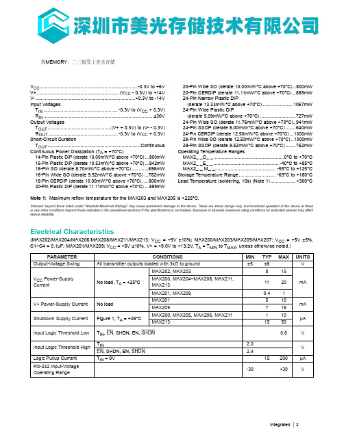
V CC ..........................................................................-0.3V to +6VV+ ..............................................................(V CC - 0.3V) to +14VV- ...........................................................................+0.3V to -14VInput VoltagesT IN ........................................................-0.3V to (V CC + 0.3V)R IN ...................................................................................±30VOutput VoltagesT OUT ................................................(V+ + 0.3V) to (V- - 0.3V)R OUT ....................................................-0.3V to (V CC + 0.3V)Short-Circuit DurationT OUT ......................................................................ContinuousContinuous Power Dissipation (T A = +70°C)14-Pin Plastic DIP (derate 10.00mW/°C above +70°C) ...800mW16-Pin Plastic DIP (derate 10.53mW/°C above +70°C) ...842mW16-Pin SO (derate 8.70mW/°C above +70°C).............696mW16-Pin Wide SO (derate 9.52mW/°C above +70°C) ...762mW16-Pin CERDIP (derate 10.00mW/°C above +70°C) .....800mW20-Pin Plastic DIP (derate 11.11mW/°C above +70°C) ...889mW 20-Pin Wide SO (derate 10.00mW/°C above +70°C) ..800mW 20-Pin CERDIP (derate 11.11mW/°C above +70°C) ...889mW 24-Pin Narrow Plastic DIP (derate 13.33mW/°C above +70°C) .......................1067mW 24-Pin Wide Plastic DIP (derate 9.09mW/°C above +70°C) ...........................727mW 24-Pin Wide SO (derate 11.76mW/°C above +70°C)..941mW 24-Pin SSOP (derate 8.00mW/°C above +70°C) ........640mW 24-Pin CERDIP (derate 12.50mW/°C above +70°C) ...1000mW 28-Pin Wide SO (derate 12.50mW/°C above +70°C) ..1000mW 28-Pin SSOP (derate 9.52mW/°C above +70°C) ........762mW Operating Temperature Ranges MAX2_ _C_ _ .....................................................0°C to +70°C MAX2_ _E_ _ .................................................-40°C to +85°C MAX2_ _ M_ _ ..............................................-55°C to +125°C Storage Temperature Range ............................-65°C to +160°C Lead Temperature (soldering, 10s) (Note 1) ...................+300°C(MAX202/MAX204/MAX206/MAX208/MAX211/MAX213: V CC = +5V ±10%; MAX200/MAX203/MAX205/MAX207: V CC = +5V ±5%, C1–C4 = 0.1µF; MAX201/MAX209: V CC = +5V ±10%, V+ = +9.0V to +13.2V, T A = T MIN to T MAX , unless otherwise noted.)PARAMETERCONDITIONS MIN TYP MAX UNITS Output-Voltage SwingAll transmitter outputs loaded with 3kΩ to ground ±5±8V V CC Power-SupplyCurrent No load, T A = +25°C MAX202, MAX203815mA MAX200, MAX204–MAX208, MAX211,MAX2131120MAX201, MAX2090.41V+ Power-Supply CurrentNo load MAX201510mA MAX209715Shutdown Supply CurrentFigure 1, T A = +25°C MAX200, MAX205, MAX206, MAX211110µA MAX2131550Input Logic Threshold LowT IN , EN , SHDN, EN, SHDN 0.8V Input Logic Threshold HighT IN 2.0V EN , SHDN, EN, SHDN 2.4Logic Pullup CurrentT IN = 0V15200µA RS-232 Input-VoltageOperating Range -30+30V Integrated │ 2Note 1: Maximum reflow temperature for the MAX203 and MAX205 is +225°C.Stresses beyond those listed under “Absolute Maximum Ratings” may cause permanent damage to the device. These are stress ratings only, and functional operation of the device at these or any other conditions beyond those indicated in the operational sections of the specifications is not implied. Exposure to absolute maximum rating conditions for extended periods may affect device reliability.Electrical Characteristics找MEMORY 、二三极管上美光存储Detailed Description The MAX200–MAX209/MAX211/MAX213 consist of three sections: charge-pump voltage converters, drivers (trans-mitters), and receivers. Each section is described in detail.+5V to ±10V Dual Charge-Pump Voltage Converter The +5V to ±10V conversion is performed by two charge-pump voltage converters (Figure 4). The first uses capaci-tor C1 to double +5V to +10V, storing +10V on the V+output filter capacitor, C3. The second chargepump volt-age converter uses capacitor C2 to invert +10V to -10V,storing -10V on the V- output filter capacitor, C4.The MAX201 and MAX209 include only the V+ to Vcharge pump, and are intended for applications that have a V CC = +5V supply and a V+ supply in the +9V to +13.2V range.In shutdown mode, V+ is internally connected to V CC by a 1kΩ pulldown resistor and V- is internally connected to ground by a 1kΩ pullup resistor.RS-232 Drivers When V CC = +5V, the typical driver output-voltage swing is ±8V when loaded with a nominal 5kΩ RS-232 receiver. The output swing is guaranteed to meet the EIA/TIA-232E and V.28 specifications, which call for ±5V minimum out-put levels under worst-case conditions. These include a minimum 3kΩ load, V CC = +4.5V, and the maximum operating temperature. The open-circuit output-voltage swing ranges from (V+ - 0.6V) to V-.Input thresholds are both CMOS and TTL compatible. The inputs of unused drivers can be left unconnected since 400kΩ pullup resistors to V CC are included onchip. Since all drivers invert, the pullup resistors force the outputs of unused drivers low. The input pullup resistors typically source 15μA; therefore, the driver inputs should be driven high or open circuited to minimize power-supply current in shutdown mode.When in low-power shutdown mode, the driver outputs are turned off and their leakage current is less than 1mA, even if the transmitter output is backdriven between 0V and (V CC + 6V). Below -0.5V, the transmitter output is diode clamped to ground with a 1kΩ series impedance. The transmitter output is also zener clamped to approxi-mately (V CC + 6V), with a 1kΩ series impedance.Figure 1. Shutdown Current Test CircuitFigure 2. Receiver Output Enable and Disable Timing MAX200–MAX209/MAX211/MAX213+5V, RS-232 Transceivers with 0.1μF External Capacitors Integrated │ 5。
Y系列电动机型号大全22050【范本模板】
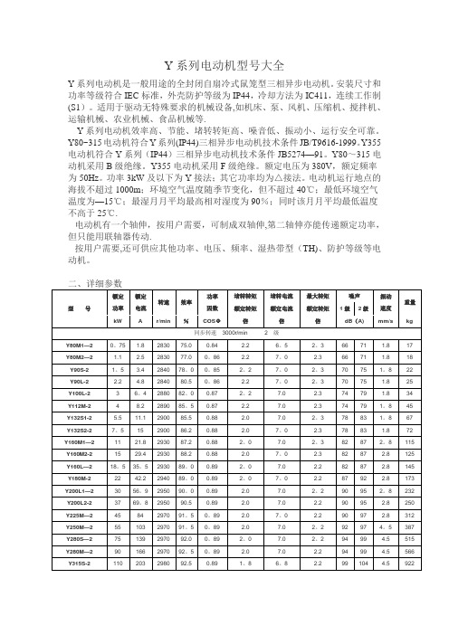
Y系列电动机型号大全Y系列电动机是一般用途的全封闭自扇冷式鼠笼型三相异步电动机。
安装尺寸和功率等级符合IEC标准,外壳防护等级为IP44,冷却方法为IC411,连续工作制(S1)。
适用于驱动无特殊要求的机械设备,如机床、泵、风机、压缩机、搅拌机、运输机械、农业机械、食品机械等.Y系列电动机效率高、节能、堵转转矩高、噪音低、振动小、运行安全可靠。
Y80~315电动机符合Y系列(IP44)三相异步电动机技术条件JB/T9616-1999。
Y355电动机符合Y系列(IP44)三相异步电动机技术条件JB5274—91。
Y80~315电动机采用B级绝缘。
Y355电动机采用F级绝缘。
额定电压为380V,额定频率为50Hz。
功率3kW及以下为Y接法;其它功率均为△接法。
电动机运行地点的海拔不超过1000m;环境空气温度随季节变化,但不超过40℃;最低环境空气温度为—15℃;最湿月月平均最高相对湿度为90%;同时该月月平均最低温度不高于25℃.电动机有一个轴伸,按用户需要,可制成双轴伸,第二轴伸亦能传递额定功率,但只能用联轴器传动.按用户需要,还可供应其他功率、电压、频率、湿热带型(TH)、防护等级等电动机。
Y355M1—109019159593.00。
81。
2 6.02。
0964。
51620 Y355M2-1011023059593.20.81。
26。
0 2.0964。
51775 Y355L1-1013227559593。
50。
8 1.2 6.0 2.096 4.51880Y2系列三相异步电动机一、概述Y2系列电动机是Y系列电机的更新换代产品,是一般用途的全封闭自扇冷式鼠笼型三相异步电动机。
它是我国九十年代最新产品,其整体水平已达到国外同类产品九十年代初的水平。
该产品应用于国民经济各个领域,如机床、水泵、风机、压缩机,也可适用于运输、搅拌、印刷、农机、食品等各类不含易燃、易爆或腐蚀性气体的场合。
Y2系列电机的安装尺寸和功率等级符合IEC标准,与德国DIN42673标准一致,也与Y系列电机一样,其外壳防护等级为IP54,冷却方法为IC41l,连续工作制(S1)。
NRLMW222M400V22X30F中文资料
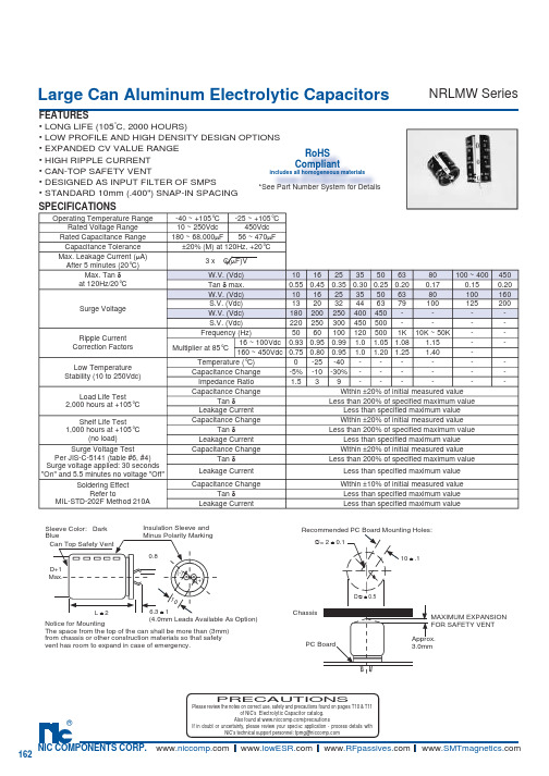
Large Can Aluminum Electrolytic CapacitorsFEATURES• LONG LIFE (105°C, 2000 HOURS)• LOW PROFILE AND HIGH DENSITY DESIGN OPTIONS • EXPANDED CV VALUE RANGE• HIGH RIPPLE CURRENT• CAN-TOP SAFETY VENT • DESIGNED AS INPUT FILTER OF SMPS• STANDARD 10mm (.400") SNAP-IN SPACING NRLMW SeriesSPECIFICATIONSNotice for MountingThe space from the top of the can shall be more than (3mm) from chassis or other construction materials so that safety vent has room to expand in case of emer g en c y.Sleeve Color: Dark BlueCan Top Safety VentInsulation Sleeve and Minus Polarity Marking(4.0mm Leads Available As Option)D+1Max.L ± 26.3 ± 10.810(-)(+)MAXIMUM EX P AN S IONFOR SAFETY VENT Approx. 3.0mmRecommended PC Board Mounting Holes:10 ± .1∅= 2 ± 0.1D ∅ ± 0.5ChassisPC BoardPRECAUTIONSPlease review the notes on correct use, safety and precautions found on pages T10 & T11of NIC’s Electrolytic Capacitor catalog . Operating Temperature Range-40 ~ +105°C -25 ~ +105°C Rated Voltage Range 10 ~ 250Vdc 450Vdc Rated Capacitance Range 180 ~ 68,000µF 56 ~ 470µF Capacitance Tolerance ±20% (M) at 120Hz, +20°CMax. Leakage Current (µA)After 5 minutes (20°C)3 x C(µF)VMax. Tan δat 120Hz/20°CW.V. (Vdc)10162535506380100 ~ 400450Tan δ max.0.550.450.350.300.250.200.170.150.20Surge VoltageW.V. (Vdc)10162535506380100160S.V. (Vdc)132032446379100125200W.V. (Vdc)180200250400450----S.V. (Vdc)220250300450500----Ripple Current Correction Factors Frequency (Hz)50601001205001K 10K ~ 50K --Multiplier at 85°C16 ~ 100Vdc0.930.950.99 1.0 1.05 1.08 1.15--160 ~ 450Vdc0.750.800.95 1.0 1.20 1.25 1.40-Low Temperature Stability (10 to 250Vdc)Temperature (°C)0-25-40------Capacitance Change -5%-10-30%------Impedance Ratio 1.539------Load Life Test 2,000 hours at +105°C Capacitance ChangeWithin ±20% of initial measured valueTan δLess than 200% of specifi ed maximum valueLeakage Current Less than specifi ed maximum value Shelf Life Test 1,000 hours at +105°C(no load)Capacitance ChangeWithin ±20% of initial measured value Tan δLess than 200% of specifi ed maximum valueLeakage Current Less than specifi ed maximum value Surge Voltage TestPer JIS-C-5141 (table #6, #4)Surge voltage applied: 30 seconds "On" and 5.5 minutes no voltage "Off"Capacitance ChangeWithin ±20% of initial measured value Tan δLess than 200% of specifi ed maximum valueLeakage Current Less than specifi ed maximum value Soldering EffectRefer toMIL-STD-202F Method 210ACapacitance ChangeWithin ±10% of initial measured valueTan δLess than specifi ed maximum value Leakage CurrentLess than specifi ed maximum valueRoHSCompliantincludes all homogeneous materials *See Part Number System for DetailsLarge Can Aluminum Electrolytic Capacitors NRLMW SeriesLarge Can Aluminum Electrolytic CapacitorsNRLMW SeriesNRLMW 471 M 250V 30X35 FRoHS compliant Case Size (mm) Voltage Rating Tolerance Code Capacitance Code SeriesPART NUMBER SYSTEM。
MGate 5101-PBM-MN 产品说明书

P/N: 1802051010013*1802051010013*MGate 5101-PBM-MN Quick Installation GuideVersion 3.1, November 2019Technical Support Contact Information /support Moxa Americas:Toll-free: 1-888-669-2872Tel: 1-714-528-6777Fax: 1-714-528-6778 Moxa China (Shanghai office): Toll-free: 800-820-5036 Tel: +86-21-5258-9955 Fax: +86-21-5258-5505 Moxa Europe:Tel: +49-89-3 70 03 99-0Fax: +49-89-3 70 03 99-99 Moxa Asia-Pacific: Tel: +886-2-8919-1230 Fax: +886-2-8919-1231 Moxa India:Tel: +91-80-4172-9088Fax: +91-80-4132-10452019 Moxa Inc. All rights reserved.OverviewThe MGate 5101-PBM-MN is an industrial Ethernet gateway for PROFIBUS-to-Modbus-TCP network communication.Package ChecklistBefore installing the MGate 5101-PBM-MN, verify that the package contains the following items:• 1 MGate 5101-PBM-MN gateway•Quick installation guide (printed)•Warranty CardPlease notify your sales representative if any of the above items are missing or damaged.Optional Accessories (can be purchased separately): •CBL-F9M9-150: DB9-female-to-DB9-male serial cable, 150 cm •CBL-F9M9-20: DB9-female-to-DB9-male serial cable, 20 cm •Mini DB9F-to-TB: DB9-female-to-terminal-block connector •WK-36-01: Wall-mounting kitHardware IntroductionLED IndicatorsLED Color FunctionPWR1 Green Power is on Off Power is offPWR2 Green Power is on Off Power is offReady GreenSteady on: Power is on and the MGate isfunctioning normallyBlinking: The MGate has been located by theMGate Manager’s Location functionRedSteady on: Power is on and the MGate is bootingupBlinking: Indicates an IP conflict, or the DHCP orBOOTP server is not responding properlyOff Power is off or fault condition existsCOMMOff No data exchangeGreen Data exchange with all slavesGreen,flashingData exchange with at least one slave (not allconfigured slaves can communicate with gateway) Red Bus control errorCFGOff No PROFIBUS configuration Green PROFIBUS configuration OKPBMOff PROFIBUS master is offlineRed PROFIBUS master is in STOP mode Green,flashingPROFIBUS master is in CLEAR mode Green PROFIBUS master is in OPERATE modeTOK Green Gateway holds the PROFIBUS tokenOff Gateway is waiting for the PROFIBUS tokenLED Color FunctionEthernet AmberSteady: 10Mbps, no data is transmittingBlinking: 10Mbps, data is transmitting GreenSteady: 100Mbps, no data is transmittingBlinking: 100Mbps, data is transmitting Off Ethernet cable is disconnectedReset ButtonThe reset button is used to load factory defaults. Use a pointed object such as a straightened paper clip to hold the reset button down for five seconds. Release the reset button when the Ready LED stops blinking. Hardware Installation ProcedureSTEP 1:Connect the power adapter. Connect the 12-48 VDC power line or DIN-rail power supply with the MGate 5101-PBM-MNdevice’s terminal block. Make sure the adapter is connected toan earthed socket.STEP 2:Use a PROFIBUS cable to connect the unit to a PROFIBUS slave device.STEP 3:Connect the unit to the Modbus TCP device.STEP 4:The MGate 5101-PBM-MN series is designed to be attached toa DIN rail or mounted on a wall. For DIN-rail mounting, pushdown the spring and properly attach it to the DIN-rail until it“snaps” into place. For wall mounting, install the wall-mountkit (optional) first and then screw the device onto the wall.Wall or Cabinet MountingTwo metal plates are provided for mounting theunit on a wall or inside a cabinet. Attach the platesto the unit’s rear panel with screws. With the platesattached, use screws to mount the unit on a wall.The heads of the screws should be 5 to 7 mm indiameter, the shafts should be 3 to 4 mm indiameter, and the length of the screws should bemore than 10.5 mm.For each screw, the head should be 6 mm or less in diameter, and the shaft should be 3.5 mm or less in diameter.The following figure illustrates the two mounting options:Software Installation InformationTo install MGate Manager, please download it from Moxa’s website at . For more detailed information about MGateManager, click the Documents button and select the MGate 5101-PBM-MN User’s Manual.The MGate 5101 also supports login via a web browser.Default IP address: 192.168.127.254Default account: adminDefault password: moxaPin Assignments PROFIBUS Serial Port (Female DB9)PINSignal Name 1– 2– 3PROFIBUS D+ 4RTS 5Signal common 65V 7– 8PROFIBUS D- 9 –Power Input and Relay Output PinoutsV2+ V2-V1+ V1- Shielded Ground DC Power Input 2 DC Power Input 2 N.O. Common N.C. DC Power Input 1 DC Power Input 1SpecificationsPower Input12 to 48 VDC Power Consumption(Input Rating)12 to 48 VDC, 360 mA (max.) Operating Temperature Standard Models: 0 to 60°C (32 to 140°F) Wide Temp. Models: -40 to 75°C (-40 to 167°F)Storage Temperature-40 to 85°C (-40 to 185°F) ATEX and IECEx Information1. ATE X Certificate number: DEMKO 14 ATEX 12882. IECEx number: IECEx UL 14.0023X3. Certificate string: Ex nA IIC T4 GcAmbient range: 0°C ≤ Tamb ≤ 60°C (for suffix without –T)Ambient range: -40°C ≤ Tamb ≤ 75°C (for suffix without –T)4. Standards covered:EN 60079-0: 2012+A11:2013/IEC 60079-0: Ed 6.0EN 60079-15:2010/IEC 60079-15: Ed 4.05. Field-wiring connection:The device uses a terminal block, solder on the power distribution board, suitable for 12-24 AWG wire size, torque value 4.5 lb-in (0.51 N-m).6. Battery information: Battery is not user replaceable.7. Installation instructions:• A 4 mm 2 conductor must be used when the connection to theexternal grounding screw is utilized.• Conductors suitable for use at an ambient temperature of 84°Cmust be used for the power supply terminal.8. Special conditions for safe use:• The device is to be installed in an IECEx/ATEX Certified IP54enclosure and accessible only through the use of a tool.• The device is for use in an area of not more than pollution degree2 in accordance with IEC 60664-1.NOTE The equipment must be suitable for use in Class 1, Division 2, Groups A, B, C, D, or nonhazardous locations only.Moxa Inc.Fl. 4, No. 135, Lane 235, Baoqiao Rd.Xindian Dist., New Taipei City, 23145, Taiwan, R.O.C.。
ABB Emax电源电路保护器说明书

16Em a x P ow e r b r e a k e rs16Emax power breakersABB’s Emax series of low voltage power circuit breakers embodies over half a century’s experience and technological development in power circuit breakers.The Emax offers a series of breakers that is totally innovative in its technological design, ease of installation and use, making it the ideal solution for the growing requirements of designers, switchboard and switchgear manufacturers, installers, OEMs and users.The Emax power circuit breakers are UL Listed and meet the ANSI Standard for low voltage power circuit breakers.ABB Emax power circuit breakers are available in fi ve different models (four sizes) with rated continuous current from 800A to 5000A and rated short-circuit current range from 42kA to 125kA (480V).Technical catalog 1SDC200003 D0201 is available upon request.BCS Switchgear Inc.Switchgear | Circuit Breakers | Parts | Tech SupportE1 E2 E3E4 E6E6Specifi cations common to the entire rangeRated max voltage 635VACRated voltage 600VACTest voltage (1min 50/60Hz) 2.2kVFrequency 50-60HzNumber of poles 3/4Versions Fixed/DrawoutE 1 S 16 X X X X X X X X X XAccessories: X = noneA = mechanical counter F = A & BB = button guardAccessories: X = none G = A & C Q = B & EA = mechanical trip indicator H = A & D R =B & FB = mechanical trip indicator J = A & E S = B,C & E& bell alarm K = A & F T = B, C & FC = padlock provision (open) L = A, C & E U = C & ED = keylock (open) M = A, C & F V = C & FE = position lock N = B & C W = D & EF = access pos. lock P = B & D Y = D & FUndervoltage trip:0 = none50/60Hz & VDC: A = 24VDC B = 30VC=48VD=60VE = 110 – 120VF = 125 – 127VG=220–240VH=250VJ = 380 – 400VAC K = 440 – 480VACSecond shunt trip: L = 24VDC M = 30VN=48VP=60VQ = 110 – 120V R = 125 – 127VS=220–240VT=250VU = 380 – 400VAC V = 440 – 480VAC1Will be shipped separately.2For withdrawable breakers, use "H".3Not available with PR112 trip units. External 15A auxiliary kit can be used.Shunt trip: 0 = none50/60Hz & VDC: A = 24VDC, B = 30V, C = 48V, D = 60V,E = 110 – 120V,F = 125 – 127V,G = 220 – 240V,H = 250V,J = 380 – 400VAC, K = 440 – 480VACSpring charging motor: (includes spring charged signal, P/N does not show)0 = none, A = 24 – 30VAC/VDC, B = 48 – 60VAC/VDC, C = 110-130VAC/VDC,D = 220 – 250VAC/VDC,E = spring charged signal onlyContacts:A = 4 auxB = 10 auxC = 15 auxD = UV energ. N.O.E = UV energ.NCF = A & DG = A & EH = B & DJ = B & E K = C & D L = C & EClosing coil: 0 = none50/60Hz & VDC: A = 24VDC, B = 30, C = 48, D = 60, E = 110 – 120, F = 125 – 127, G = 220– 240, H = 250, J = 380 – 400VAC, K = 440 – 480VACTerminal types: (1st letter is upper terminal, 2nd letter is lower terminal)H = rear horz 2., V = rear vert. 1H = HH, V = VVA = HV,B = VHTrip unit: A = PR111/P, LI B = PR111/P, LSI C = PR111/P, LSIGD = non-automaticE = PR112/P, LSIF = PR112/P, LSIGG = PR112/PD, LSI H = PR112/PD, LSIG N = PR113/PP = PR113/PDVersion: B = fi xed breaker, UL; D = withdrawable breaker, UL, less cradleMax. ampere rating: 02 = 250, 04 = 400, 08 = 800, 10 = 1000, 12 = 1200, 16 = 1600, 20 = 2000, 25 = 2500, 32 = 3200,36 = 3600, 40 = 4000, 50 = 5000Breaking capacity: B = basic, N = normal, S = standard, H = high, V = very highFrame size: 1 = 1, 3P; 2 = 2, 3P; 3 = 3, 3P; 4 = 4, 3P; 6 = 6, 3P; A = 1, 4P; B = 2, 4P, C = 3, 4P; D = 4, 4P; F = 6, 4PE 1 X 12 X X XAccessories : X = none A = Shutter padlockContacts : 0 = none, A = 5 position auxiliaries B = 10 position auxiliariesVersion : K = cradle, ULV = cradle for E3VMax. ampere rating : UL: 12 = 1200 (E1); 16 = 1600 (E2); 20 = 2000 (E3); 25 = 2500 (E3); 36 = 3600 (E4); 50 = 5000 (E6)Frame size : 1 = 1, 3P; 2 = 2, 3P; 3 = 3, 3P; 4 = 4, 3P; 6 = 6, 3P; A = 1, 4P; B = 2, 4P; C = 3, 4P; D = 4, 4P; F = 6, 4PTerminal types :(1st letter is upper terminal, 2nd letter is lower terminal) H = rear horz., V = rear vert. H = HH, V = VV A = HV , B = VHGeneral informationStandard featuresNOTE: Switches provided standard without 4 auxiliary contacts.Standard features – manually operated UL breaker • Rear horizontal terminals• PR111 trip unit with LI protection functions• Manual mechanical close and open pushbuttons• CB open/closed mechanical indicator• Spring charged/discharged mechanical indicator• 2NO & 2NC auxiliary contacts for open/closed position indication • Lifting plates• Current transformers• Terminal boxFixed breakersFixed breakersStandard features – manually operated UL breaker• Rear horizontal terminals• PR111 trip unit with LI protection functions• Manual mechanical close and open pushbuttons • CB open/closed mechanical indicator• Spring charged/discharged mechanical indicator• 2NO & 2NC auxiliary contacts for open/closed position indication • Lifting plates • Current transformers • Terminal boxNeutral pole rating• E1 – E3 = 100% rating• E4 – E6 = 50% ratingWithdrawable breakersStandard features – electrically operated breakerMoving part• PR111 trip unit with LI protection feature• Spring charging motor• Shunt trip• Closing coil• Manual mechanical close and open pushbuttons• CB open/closed mechanical indicator• Spring charged/discharged mechanical indicator• 2NO & 2NC auxiliary contacts for open-closed position indication• Lifting plates• Current transformers• Racking device with closed door• Circuit breaker racking position indicator• Sliding contacts• Fail safe device (not available with YU)Standard features – electrically operated breakerFixed part• Safety shutters• Rear horizontal terminals• Sliding contacts• Anti-insertion lock• Ground connectionWithdrawable breakersStandard features – electrically operated breaker Moving part• PR111 trip unit with LI protection feature • Spring charging motor • Shunt trip • Closing coil• Manual mechanical close and open pushbuttons • CB open/closed mechanical indicator• Spring charged/discharged mechanical indicator• 2NO & 2NC auxiliary contacts for open-closed position indication • Lifting plates • Current transformers• Racking device with closed door• Circuit breaker racking position indicator • Sliding contacts• Fail safe device (not available with YU)Standard features – electrically operated breaker Fixed part• Safety shutters • Rear horizontal terminals • Sliding contacts • Anti-insertion lock • Ground connectionNeutral pole rating• E1 – E3 = 100% rating • E4 – E6 = 50% ratingStandard features – manually operated UL switch • Rear horizontal terminals• Manual mechanical close and open pushbuttons• CB open/closed mechanical indicator• Spring charged/discharged mechanical indicator• Lifting plates• Terminal boxFixed switchesStandard features – manually operated UL switch• Rear horizontal terminals• Manual mechanical close and open pushbuttons • CB open/closed mechanical indicator• Spring charged/discharged mechanical indicator • Lifting plates • Terminal boxFixed switchesNeutral pole rating• E1 – E3 = 100% rating• E4 – E6 = 50% ratingStandard features – manually operated switchFixed part• Safety shutters• Rear horizontal terminals• Sliding contacts• Anti-insertion lock• Ground connectionWithdrawable switchesStandard features – manually operated switchMoving part• Manual mechanical close and open pushbuttons• Circuit breaker open/closed mechanical indicator• Spring charged/discharged mechanical indicator• Lifting plates• Racking device with closed door• Circuit breaker racking position indicator• Sliding contacts• Fail-safe device (not available with YU)Standard features – manually operated switches Fixed part• Safety shutters • Rear horizontal terminals • Sliding contacts • Anti-insertion lock • Ground connectionNeutral pole rating• E1 – E3 = 100% rating • E4 – E6 = 50% ratingWithdrawable switchesStandard features – manually operated switch Moving part• Manual mechanical close and open pushbuttons • Circuit breaker open/closed mechanical indicator • Spring charged/discharged mechanical indicator • Lifting plates• Racking device with closed door• Circuit breaker racking position indicator • Sliding contacts• Fail-safe device (not available with YU)1 Without intentional delays.2 Consult factory for drawings.E1 E2 E3 E4Specifi cations common to the entire rangeVoltagesRated service voltage Ue 690~ / 250– VRated insulation voltage Ui 1000 VRated impulse withstand voltage Uimp 12 kVService temperature -5 …+70 °CStorage temperature -40 …+70 °CHzFrequency f50–60Number of poles 3–4Versions Fixed / WithdrawableE6Circuit breaker type1Without intentional delays.2Consult factory for drawings.E 1 S 16 X X X X X X X X X XAccessories: X = noneA = mechanical counter F = A & BB = button guardAccessories: X = none G = A & C Q = B & EA = mechanical trip indicator H = A & D R =B & FB = mechanical trip indicator J = A & E S = B,C & E& bell alarm K = A & F T = B, C & FC = padlock provision (open) L = A, C & E U = C & ED = keylock (open) M = A, C & F V = C & FE = position lock N = B & C W = D & EF = access pos. lock P = B & D Y = D & FUndervoltage trip:0 = none50/60Hz & VDC: A = 24VDC B = 30VC=48VD=60VE = 110 – 120VF = 125 – 127VG=220–240VH=250VJ = 380 – 400VAC K = 440 – 480VACSecond shunt trip: L = 24VDC M = 30VN=48VP=60VQ = 110 – 120V R = 125 – 127VS=220–240VT=250VU = 380 – 400VAC V = 440 – 480VACShunt trip: 0 = none50/60Hz & VDC: A = 24VDC, B = 30, C = 48, D = 60, E = 110 – 120,F = 120 – 127,G = 220 – 240,H = 240 - 250, J = 380 – 400VAC,K = 440 – 480VACSpring charging motor: (includes spring charged signal, P/N does not show)0 = none, A = 24 – 30VAC/VDC, B = 48 – 60VAC/VDC, C = 110-130VAC/VDC,D = 220 – 250VAC/VDC,E = spring charged signal onlyClosing coil: 0 = none50/60Hz & VDC: A = 24VDC, B = 30, C = 48, D = 60, E = 110 – 120, F = 120 – 127,G = 220 – 240, H = 240 - 250, J = 380 – 400VAC, K = 440 – 480VACTerminal types: (Ist letter is upper terminal, 2nd letter is lower terminal) 1H = rear horz., V = rear vert., F = front, L = rear fl atH = HH, V = VV, F = FF, L = LL,A = HV,B = VH,C = HF,D = FH,E = HL, G = LH, J = VF, K = FV, M = VL, N = LV,P = FL, Q = LFVersion: F = fi xed breaker, IEC; W = withdrawable breaker, IEC, less cradleMax. ampere rating: 02 = 250, 04 = 400, 08 = 800, 10 = 1000, 12 = 1250, 16 = 1600, 20 = 2000, 25 = 2500, 32 = 3200,40 = 4000, 50 = 5000, 63 = 6300Breaking capacity: B = basic, N = normal, S = standard, H = high, V = very high, L = limitingFrame size: 1 = 1, 3P; 2 = 2, 3P; 3 = 3, 3P; 4 = 4, 3P; 6 = 6, 3P; A = 1, 4P; B = 2, 4P; C = 3, 4P; D = 4, 4P; F = 6, 4P1 For withdrawable breakers, use "H".2Not available with PR112 trip units; use external 15 auxiliary kit.Trip unit: A = PR111/P, LI B = PR111/P, LSI C = PR111/P, LSIGD = non-automaticE = PR112/P, LSIF = PR112/P, LSIGG = PR112/PD, LSI H = PR112/PD, LSIG N = PR113/PP = PR113/PDContacts:A = 4 auxB = 10 auxC = 15 auxD = UV energ. N.O.E = UV energ.NCF = A & DG = A & EH = B & DJ = B & E K = C & D L = C & EE 1 X 12 X X XAccessories : X = none A = Shutter padlockContacts : 0 = none A = 5 position auxiliaries B = 10 position auxiliariesVersion : C = cradle, IECMax. ampere rating : IEC: 12 = 1250 (E1); 20 = 2000 (E2); 32 = 3200 (E3); 40 = 4000 (E4); 63 = 6300 (E6)Frame size :1 = 1, 3P;2 = 2, 3P;3 = 3, 3P;4 = 4, 3P; 6 = 6, 3P A = 1, 4P; B = 2, 4P; C = 3, 4P; D = 4, 4P; F = 6, 4PTerminal types :(Ist letter is upper terminal, 2nd letter is lower terminal.) H = rear horz., V = rear vert., F = front, L = rear fl at H = HH, V = VV , F = FF , L = LL,A = HV ,B = VH,C = HF ,D = FH,E = HL, G = LH, J = VF , K = FV , M = VL, N = LV , P = FL, Q = LFGeneral informationStandard featuresNOTE: Switches provided standard without 4 auxiliary contacts.Fixed breakersStandard features – manually operated breaker Fixed breaker• Rear horizontal terminals• PR111 trip unit with LI protection functions• Manual mechanical close and open pushbuttons• CB open/closed mechanical indicator• Spring charged/discharged mechanical indicator• 2NO & 2NC auxiliary contacts for open-closed position indication • Lifting plates• Current transformers• Terminal boxFixed breakersStandard features – manually operated breaker Fixed breaker• Rear horizontal terminals• PR111 trip unit with LI protection functions• Manual mechanical close and open pushbuttons • CB open/closed mechanical indicator• Spring charged/discharged mechanical indicator• 2NO & 2NC auxiliary contacts for open-closed position indication • Lifting plates • Current transformers • Terminal boxNeutral pole rating• E1 – E3 = 100% rating• E4 – E6 = 50% rating 11 Consult factory for special 100% neutral pole rating.Standard features – electrically operated breakerMoving part• PR111 trip unit with LI protection functions• Spring charging motor• Shunt trip• Closing coil• Manual mechanical close and open pushbuttons• CB open/closed mechanical indicator• Spring charged/discharged mechanical indicator• 2NO & 2NC auxiliary contacts for open-closed position indication• Lifting plates• Current transformers• Racking device with closed door• Circuit breaker racking position indicator• Sliding contactsWithdrawable breakersStandard features – electrically operated breakerFixed part• Safety shutters• Rear horizontal terminals• Sliding contacts• Anti-insertion lock• Ground connectionStandard features – electrically operated breaker Moving part• PR111 trip unit with LI protection functions • Spring charging motor • Shunt trip • Closing coil• Manual mechanical close and open pushbuttons • CB open/closed mechanical indicator• Spring charged/discharged mechanical indicator• 2NO & 2NC auxiliary contacts for open-closed position indication • Lifting plates • Current transformers• Racking device with closed door• Circuit breaker racking position indicator • Sliding contactsWithdrawable breakersStandard features – electrically operated breakerFixed part• Safety shutters • Rear horizontal terminals • Sliding contacts • Anti-insertion lock • Ground connectionNeutral pole rating• E1 – E3 = 100% rating • E4 – E6 = 50% rating 11 Consult factory for special 100% neutral pole rating.Fixed switches, 3 poleStandard features – manually operated switch • Rear horizontal terminals• Manual mechanical close and open pushbuttons• Circuit breaker open/closed mechanical indicator• Spring charged/discharged mechanical indicator• Lifting plates• Terminal boxFixed switches, 4 poleStandard features – manually operated switch• Rear horizontal terminals• Manual mechanical close and open pushbuttons • Circuit breaker open/closed mechanical indicator • Spring charged/discharged mechanical indicator • Lifting plates • Terminal boxNeutral pole rating• E1 – E3 = 100% rating• E4 – E6 = 50% rating 11 Consult factory for special 100% neutral pole rating.Withdrawable switches, 3 poleStandard features – manually operated switchMoving part• Manual mechanical close and open pushbuttons• Circuit breaker open/closed mechanical indicator• Spring charged/discharged mechanical indicator• Lifting plates• Racking device with closed door• Circuit breaker racking position indicator• Sliding contactsStandard features – manually operated switchFixed part• Safety shutters• Rear horizontal terminals• Sliding contacts• Anti-insertion lock• Ground connectionWithdrawable switches, 4 poleStandard features – manually operated switch Moving part• Manual mechanical close and open pushbuttons • Circuit breaker open/closed mechanical indicator • Spring charged/discharged mechanical indicator • Lifting plates• Racking device with closed door• Circuit breaker racking position indicator • Sliding contactsStandard features – manually operated switchFixed part• Safety shutters • Rear horizontal terminals • Sliding contacts • Anti-insertion lock • Ground connectionNeutral pole rating• E1 – E3 = 100% rating • E4 – E6 = 50% rating 11 Consult factory for special 100% neutral pole rating.1Order as alternative to UV trip.1Order as alternative to various types of interlock and kirk key lock. For mounting on fi xed breaker, also requires accessory 32 (KE6MLP).1Keylock number when factory installed is N3004222. 2Also requires position lock (accessory 29).36a. Neutral current transformer (required for 4 wire ground fault systems)1 IEC only.37. Mechanical interlocks (base plate for fi xed circuit breaker)38. Interlock for fi xed circuit breaker/fi xed part of withdrawable circuit breaker (cable attachment plate)39. Interlock for fi xed circuit breaker/moving part of withdrawable circuit breaker (internal interlocking shaft)1Order as an alternative to the Accessory number 15 auxiliary contact (see page 16.27) and kirk key lock.41. Electronic time delay for undervoltage release 143. Kirk key lock adaptor plate (in open position) 244. Kit for converting fi xed breaker with rear horizontal terminals to rear vertical (set of three terminals)1 IEC only.2Kirk key not provided. Order as an alternative to the various types of interlocks and auxiliary contacts (see Accessory 26c and 26d on page 16.27).Part."Z"。
各种开关电源变压器各种高频变压器参数EEEEEEEIEI等等的参数

功率铁氧体磁芯常用功率铁氧体材料牌号技术参数EI型磁芯规格及参数PQ型磁芯规格及参数EE型磁芯规格及参数EC、EER型磁芯规格及参数1,磁芯向有效截面积:Ae2,磁芯向有效磁路长度:le3,相对幅值磁导率:μa4,饱和磁通密度:Bs1磁芯损耗:正弦波与矩形波比较一般情况下,磁芯损耗曲线是按正弦波+/-交流(AC)激励绘制的,在标准的和正常的时候,是不提供极大值曲线的。
涉及到开关电源电路设计的一个共同问题是正弦波和矩形波激励的磁芯损耗的关系。
对于高电阻率的磁性材料如类似铁氧体,正弦波和矩形波产生的损耗几乎是相等的,但矩形波的损耗稍微小一些。
材料中存在高的涡流损耗(如大一般情况下,具有矩形波的磁芯损耗比具有正弦波的磁芯损耗低一些。
但在元件存在铜损的情况下,这是不正确的。
在变压器中,用矩形波激励时的铜损远远大于用正弦波激励时的铜损。
高频元件的损耗在铜损方面显得更多,集肤效应损耗比矩形波激励磁芯的损耗给人们的印象更深刻。
举个例子,在20kHz、用17#美国线规导线的绕组时,矩形波激励的磁芯损耗几乎是正弦波激励磁芯损耗的两倍。
例如,对于许多开关电源来说,具有矩形波激励磁芯的5V、20A和30A输出的电源,必须采用多股绞线或利兹(Litz)线绕制线圈,不能使用粗的单股导线。
2Q值曲线所有磁性材料制造厂商公布的Q值曲线都是低损耗滤波器用材料的典型曲线。
这些测试参数通常是用置于磁芯上的最适用的绕组完成的。
对于罐形磁芯,Q值曲线指出了用作生成曲线时的绕组匝数和导线尺寸,导线是常用的利兹线,并且绕满在线圈骨架上。
对于钼坡莫合金磁粉芯同样是正确的。
用最适合的绕组,并且导线绕满了磁芯窗口时测试,则Q值曲线是标准的。
Q值曲线是在典型值为5高斯或更低的低交流(AC)激励电平下测量得出的。
由于在磁通密度越高时磁芯的损耗越大,故人们警告,在滤波电感器工作在高磁通密度时,磁芯的Q值是较低的。
3电感量、AL系数和磁导率在正常情况下,磁芯制造厂商会发布电感器和滤波器磁芯的AL系数、电感量和磁导率等参数。
BY229X-400中文资料
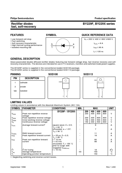
BY329
Ths(max) / C 54
D = 1.0
0.5
78
10
0.2
102
0.1
5
I
tp
D
=
tp T
126
T
t
0
150
0
2
4
6
8
10
12
IF(AV) / A
Fig.2. Maximum forward dissipation, PF = f(IF(AV)); square wave current waveform; parameter D = duty
-
current
t = 8.3 ms
-
11
A
16
A
60
A
66
A
sinusoidal; Tj = 150 ˚C prior to surge; with
I2t
I2t for fusing
reapplied VRWM(max)
t = 10 ms
-
18
A2s
Tstg
Storage temperature
Tj
1
BY329
IF = 10 A 10 A
2A 1A 2A 1A
0
150
0
2
4
6
8
IF(AV) / A
Fig.3. Maximum forward dissipation, PF = f(IF(AV)); sinusoidal current waveform; parameter a = form
factor = IF(RMS)/IF(AV).
Product specification
Acer AcerNote 系列产品参数配置说明书
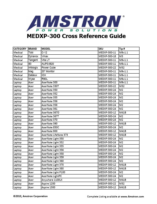
MODEL Aspire 1350 Aspire 1360 Aspire 1400 Aspire 1415 Aspire 1450 Aspire 1500 Aspire 1510 Aspire 1520 Aspire 1610 Aspire 1621 Aspire 1623 Aspire 1624 Aspire 1640 Aspire 1640LC Aspire 1650 Aspire 1661 Aspire 1662 Aspire 1663 Aspire 1664 Aspire 1670 Aspire 1672 Aspire 1673 Aspire 1674 Aspire 1680 Aspire 1681 Aspire 1682 Aspire 1683 Aspire 1684 Aspire 1685 Aspire 1689 Aspire 1690 Aspire 1691 Aspire 1692 Aspire 1693 Aspire 1694 Aspire 1695 Aspire 2000 Aspire 2001 Aspire 2002 Aspire 2003 Aspire 2010 Aspire 2012 Aspire 2013 Aspire 2014 Aspire 2016 Aspire 2020
ቤተ መጻሕፍቲ ባይዱ
©2010, Amstron Corporation
SKU MEDXP-300-22 MEDXP-300-22 MEDXP-300-22 MEDXP-300-22 MEDXP-300-22 MEDXP-300-22 MEDXP-300-22 MEDXP-300-22 MEDXP-300-22 MEDXP-300-12 MEDXP-300-22 MEDXP-300-22 MEDXP-300-22 MEDXP-300-22 MEDXP-300-22 MEDXP-300-22 MEDXP-300-22 MEDXP-300-22 MEDXP-300-22 MEDXP-300-22 MEDXP-300-22 MEDXP-300-22 MEDXP-300-22 MEDXP-300-22 MEDXP-300-24 MEDXP-300-22 MEDXP-300-22 MEDXP-300-22 MEDXP-300-22 MEDXP-300-22 MEDXP-300-22 MEDXP-300-22 MEDXP-300-22 MEDXP-300-22 MEDXP-300-22 MEDXP-300-24 MEDXP-300-22 MEDXP-300-22 MEDXP-300-22 MEDXP-300-22 MEDXP-300-22 MEDXP-300-22 MEDXP-300-22 MEDXP-300-22 MEDXP-300-22 MEDXP-300-22
空气断路器IZMX系列紧凑、灵活、高效说明书
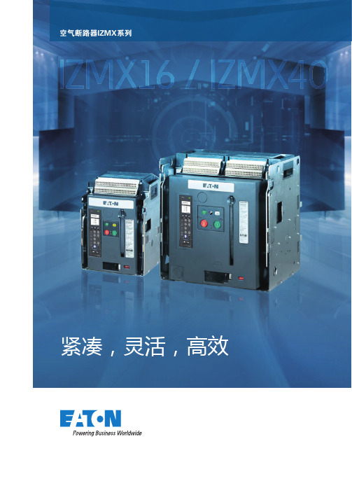
2多功能空气断路器 - IZMX系列最大额定电流4000A 最高分断能力105kA适用于各种高性价比以及优化的解决方案IZMX 系列中的IZMX16是全球最小的空气断路器之一:体积仅有0.024立方米,前表面的面积不足0.1平方米,仅比一张A4纸稍大一点!而所有的这一切都不以牺牲性能为前提。
IZMX16可以在440VAC 下达到惊人的66kA 的电流分断能力。
这在相近尺寸的空气断路器中处于领先的水平。
由于采用的创新的设计理念,用户可以将两台抽屉式断路器安装在600mm 柜宽的同一个单元格中。
这样可确保更经济的柜体空间设计,并节省操作空间。
在如此紧凑的空间内,IZMX16还能够选配装备储能电机和分/合闸线圈,方便用户远程的操作。
IZMX40在深度仅为400mm 的框架内实现了4000A 的额定电流。
而且无需在连接区域安装任何额外的铜排。
得益于灵活的连接方式,IZMX 系列经过测试并集成到伊顿的低压开关柜系统中,包括Modan ,xEnergy 和Power Xpert 系列。
证明了其出色的技术参数和良好的兼容性模块化的结构,细致的集成方 案,完整的附件选择以及各种附加功能使该断路器能够轻易地适应各种应用场合。
IZMX 系列的其他特性包括:灵活的铜排连接方式:可水平或垂直连接,也可从上方或下方直接连接在断路器背面;全新的PXR 电子脱扣器平台,更具性价比的测量,通讯和中文显示方案••水平安装主接线垂直安装主接线(仅B, N 和H 型,E 型仅可水平安装)3全新一代的电子脱扣器平台:Power Xpert Release (PXR)PXR电子脱扣器Profi bus-DP Modbus Ethernet板载Modbus丰富的通讯方案提高了操作的安全性和灵活性通过配置相应的通讯模块 - 包括集成的Modbus ,外置的PCAM (P r o f i b u s -D P ),M C A M (Modubus)或ECAM (以太网)模块,为IZMX 系列断路器配备现代化的通讯能力。
安规电容 222K400V
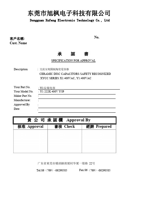
CQC19001234621
Y
0
Lead
Lead
Style Spacin
g
L
0:10mm
Y 7:7.5mm
K D
Rated Voltage
X1:400V AC Y1:400V AC
2
Lead Length
2:25 mm Min. 3:3.5±1 mm 5:5±1 mm
N
RoHS
H:HF N:RoHS
TUV X1, Y1 Class baned on
UL /CSA
X1, Y1 Class baned on FOWX2.E509457
2. Approval Standard and Recognized No.
UL/CSA
Standard No. F0WX2.E509457
Certificate No. E509457
XYCC
Safety Standard Recognized Ceramic Capacitor
1.This specification is applied to following Safety Standard Recognized Ceramic Capacitor for Electronics Appliance.
Ex. 2019
1(January)
91
2(February)
92
:
:
:
10(October)
9O
11(November) 9N
12(December) 9D
6. Approval Mark:
TUV Approval Mark:
C: Made in DONG GUAN
