CTA3F1CCP121中文资料
ccar121r2大型飞机公共航空运输承运人 运行合格审定规则

大型飞机公共航空运输承运人运行合格审定规则(1999年5月5日公布,2000年7月18日第一次修订,2005年2月25日第二次修订)CCAR-121FS-R2《大型飞机公共航空运输承运人运行合格审定规则》目录A章 总 则 4B章 运行合格审定的一般规定 7C章 管理运行合格证持有人的一般规定 12E章 国内、国际定期载客运行的航路的批准 16F 章 补充运行的区域和航路批准 19G章 手册的要求 22H章 飞机的要求 26I章 飞机性能使用限制 29J 章 特殊适航要求 36K章 仪表和设备要求 39L 章 飞机维修 64M章 机组成员和其他航空人员的要求 70N章 训练大纲 73O章 机组成员的合格要求 88P章 机组成员值勤期限制、飞行时间限制 和休息要求 95Q章 飞行签派员的合格要求和值勤时间限制 100T章 飞行运作 102U章 签派和飞行放行 119V章 记录和报告 132W章 双发飞机延伸航程运行(ETOPS) 138X 章 应急医疗设备和训练 149Y章 罚则 150Z章 附 则 152附件A 定义 153附件B 急救箱和应急医疗箱 156附件C 本规则第121.161条规定的应急撤离程序演示准则 158附件D 飞行训练要求 160附件E 熟练检查要求 172附件F 民用飞机训练分级 180附件G 高级飞行模拟机的使用 181附件H 双发飞机延伸航程运行(ETOPS) ——运行和飞机合格审定要求 183附件I 多普勒雷达和惯性导航系统 192第二次修订说明 196A章 总 则第121.1条 目的和依据为了对大型飞机公共航空运输承运人进行运行合格审定和持续监督检查,保证其达到并保持规定的运行安全水平,根据《中华人民共和国民用航空法》和《国务院对确需保留的行政许可项目设定行政许可的决定》制定本规则。
第121.3条 适用范围(a)本规则适用于在中华人民共和国境内依法设立的航空运营人实施的下列公共航空运输运行:(1)使用最大起飞全重超过5700千克的多发飞机实施的定期载客运输飞行;(2)使用旅客座位数超过30座或者最大商载超过3400千克的多发飞机实施的不定期载客运输飞行;(3)使用最大商载超过3400千克的多发飞机实施的全货物运输飞行。
CCAR-121新旧版对照表
CCAR-121 新旧版对照表新旧版CCAR-121差异说明根据民航总局第140号局长令,《大型飞机公共航空运输承运人运行合格审定规则》第二次修订版(编号CCAR-121,R2)于2005年6月1日起施行。
按照CCAR-121-R2的规定,在2005年4月1日之前按旧版CCAR-121FS通过审定的合格者持有人,应当与2007年1月1日之前,通过按照CCAR-121-R2进行的补充审定,为此公司计划于2006年上半年接受局方的补充审定。
按照总签刘副经理的布置,为方便大家学习,现将新旧版本的主要差异说明如下,大家可以用下列目录链接查询有关章节A章总则 2B章运行合格审定的一般规定 2C章管理运行合格证持有人的一般规定 3E章国内、国际定期载客运行的航路的批准 3补充运行的区域和航路批准 3 F 章G章手册的要求 4H章飞机的要求 4I章飞机性能使用限制 4J 章特殊适航要求 5K章仪表和设备要求 5L 章飞机维修 6M章机组成员和其他航空人员的要求 6N章训练大纲 6O章机组成员的合格要求 7P章机组成员值勤期限制、飞行时间限制和休息要求 8 Q章飞行签派员的合格要求和值勤时间限制 8T章飞行运作 8U章签派和飞行放行 10V章记录和报告 11W章双发飞机延伸航程运行(ETOPS) 11X 章应急医疗设备和训练 12Y章罚则 12Z章附则 12附件A 定义 12附件B 急救箱和应急医疗箱 13附件C 本规则121.161规定的应急撤离程序演示准则 13 附件D 飞行训练要求 13附件E 熟练检查要求 13附件F 民用飞机训练分级 13附件G 高级飞行模拟机的使用 13附件H 双发飞机延伸航程运行(ETOPS) ——运行和飞机合格审定要求 13 附件I 多普勒雷达和惯性导航系统 13第二次修订说明 131新版CCAR-121 旧版CCAR-121 主要差异A章总则 A分部总则121.1 [目的和依据] 121.1 [目的和依据] 针对于CCAR135部适用于小型飞机的承运人,将“公共航空运输承运人”改为“大型飞机公共运输承运人”;根据文件增加《国务院对确需保留的行政许可项目设定行政许可的决定》 121.3 [适用范围] 121.3 [适用范围] 涉及适用范围描述更为详实:除了起飞全重超过5700kg的飞机定期载客运行外,增加30座以上飞机的不定期载客或最大商载超过3400kg的飞机实施的运行描述国内定期载客,国际定期载客和补充运行的概念含有,明确邮件运输视为货物运输,同时载运旅客和货物的运输视为载客运输。
CSC121A讲稿

保护功能:综合重合闸
重合闸的放电条件: a)重合闸方式在停用位置; b)重合闸在单重方式时保护动作三跳或开关断开三相; c)有发变组三跳开入; d)I线和II线同时或先后(在同一个重合闸周期内)启动重合闸; e)重合闸启动过程中,收到相邻断路器合闸信号后又收到保护动作信号。则认 为相邻断路器先合到永久故障,给重合闸放电。 f)收到外部闭锁重合闸信号(如手跳、永跳、操作箱失电闭锁重合闸等); g)重合闸启动前,收到低气压闭锁重合闸信号,经200ms延时后“放电”。 h)失灵保护、死区保护、三相不一致、充电保护动作的同时“放电”。 i)重合闸出口命令发出的同时“放电”; j)重合闸“充电”未满时,跳闸位置继电器TWJ动作或有保护启动重合闸信号 等开入; k)装置出现“致命”错误而告警I。
保护功能:三相不一致保护
三相不一致保护功能可经零序电流、负序电流和三相跳位不一致三种元件判 别开放,还可经重合闸启动闭锁,这四种方式均可由控制字投退。 启动元件: 三相不一致保护由三相不一致输入触点启动,三相不一致输入触点消失则三 相不一致保护复归。三相不一致输入触点由分相断路器辅助触点或分相位置 继电器触点组合成的断路器三相不一致状态触点提供。若长期有三相不一致 输入触点信号,则告警,报“闭锁不一致保护”。 三相不一致保护的动作条件: 三相不一致保护已启动,满足跳位不一致和单相启动重合闸闭锁条件后,大 于三相不一致零序或负序电流定值(当三相不一致经零序或负序电流开放 时),等待延时(TBP)到后三相不一致开出输出接点闭合。
瞬时重跳功能 失灵保护启动后,收到单相跳闸命令,且相应相电流大于失灵高定值,则瞬 时重跳该相。跳闸命令或电流收回,瞬时重跳命令收回。若收到两相或三相 跳闸命令,任一相电流大于失灵高定值,则瞬时重跳三相。若同时收到两侧 的跳闸命令或收到跳闸命令时还有沟通三跳信号(从重合闸模块来),且任 意相电流大于失灵高定值,则瞬时重跳三相。外部跳闸命令收回或电流条件 不满Ⅰ段 a)启动条件: (1)电流突变量启动则充电保护启动; (2)过流辅助启动则充电保护启动; (3)零序辅助启动则充电保护启动。 b)动作条件: (1)充电保护启动; (2)任一相达到充电保护Ⅰ段电流定值,经一段延时后出口跳闸。
CTA3FM1UCP121中文资料

Distributor: Electro-Stock Tel: 630-682-1542 Fax: 630-682-1562FEATURES:• Large switching capacity up to 80A • Small size and light weight• PCB pin and quick connect mounting available • Suitable for automobile and lamp accessories• QS-9000, ISO-9002 Certified Manufacturing28.5 x 28.5 x 26.5 (40.0) mmCONTACT DATAContact Arrangement1A = SPST N.O. 1B = SPST N.C. 1C = SPDT1U = SPST N.O. (2 terminals) Contact Configuration StandardHeavy Duty Contact Rating1A 1B 1C 1U 60A @ 14VDC 40A @ 14VDC 60A @ 14VDC N.O. 40A @ 14VDC N.C. 2x25A @ 14VDC80A @ 14VDC 70A @ 14VDC 80A @ 14VDC N.O. 70A @ 14VDC N.C. 2x25A @ 14VDCContact Resistance < 30 milliohms initial Contact MaterialAgSnO 2In 2O 3 Maximum Switching Power 980W Maximum Switching Voltage 75VDC Maximum Switching Current 80ACOIL DATACoil VoltageVDCCoil ResistanceΩ ± 10%Rated Max.1.8W Pick Up Voltage VDC (max)75%of rated voltageRelease Voltage VDC (min)10%of rated voltageCoil PowerWOperate TimemsRelease Timems6 7.8 20 4.2 0.6 12 15.6 80 8.4 1.2 24 31.232016.8 2.41.8 7 5CAUTION:1. The use of any coil voltage less than the rated coil voltage may compromise the operation of the relay.2. Pickup and release voltages are for test purposes only and are not to be used as design criteria.GENERAL DATAElectrical Life @ rated load Mechanical Life 100K cycles, typical 10M cycles, typical Insulation Resistance 100M Ω min @ 500VDC Dielectric Strength, Coil to Contact Contact to Contact 500V rms min. @ sea level 500V rms min. @ sea level Shock Resistance 147m/s 2 for 11ms Vibration Resistance 1.5mm double amplitude 10-40Hz Terminal (Copper Alloy) Strength 8N (Quick Connect), 4N (PCB Pins) Operating Temperature Storage Temperature -40 °C to + 85 °C -40 °C to + 155 °C Solderability 230 °C ± 2 °C for 10 ± 0.5sWeight 46gDistributor: Electro-Stock Tel: 630-682-1542 Fax: 630-682-1562ORDERING INFORMATION1. Series:24VDCCTA3 standardCTA3F with mounting flangeCTA3M with metal bracket CTA3F 2.Contact Arrangement: 1A = SPST N.O. 1B = SPST N.C. 1C = SPDT1U = SPST N.O. **Only available with standard contacts 1C3. Sealing Options: S = Sealed C = Dust CoverS 4. Termination Options: P = PCB PinsQ = Quick Connect P 5. Coil Voltage: 6VDC 12VDC 24VDC2 6. Contacts: 1 = Standard 2 = Heavy Duty 7: Coil Suppression: Blank = StandardD = Diode (1N4005) Cathode on “86” terminal R = Resistor (680 Ohms) 2D = 2 diodes (1N4005)DR = Diode & Resistor (1N4005 & 680 Ohms) Cathode on “86” terminal ** Consult factory if other values are needed.DIMENSIONS – CTA3 (Units = mm)Standard contacts (1) with PC PinsStandard contacts (1) with Quick ConnectsHeavy duty contacts (2) with PC PinsHeavy duty contacts (2) with Quick ConnectsDistributor: Electro-Stock Tel: 630-682-1542 Fax: 630-682-1562DIMENSIONS – CTA3F (Units = mm)Standard contacts (1) with Quick Connects Heavy duty contacts (2) with Quick Connects DIMENSIONS – CTA3M (Units = mm)Standard contacts (1) with Quick Connects Heavy duty contacts (2) with Quick Connects SCHEMATICS, PC PIN DIMENSIONS, & PC LAYOUTS (BOTTOM VIEWS)1A 1B1C 1U。
CSC-121A 开关保护使用说明书
6.1 安装 ................................................................................................................................................. 22 6.2 通电前的检查 ................................................................................................................................. 22 6.3 开关电源检查 .................................................................................................................................. 23 6.4 绝缘电阻测量 ................................................................................................................................. 23 6.5 装置上电设置 ................................................................................................................................. 24
第二章CT121的系统流程简介

SO2吸收部分
吸收塔内浆液被吸收塔搅拌器适当地搅拌,使 石膏晶体悬浮. 由氧化风机吹出的氧化空气进入吸收塔的反应 区,使被吸收的SO2氧化. 将石灰石浆液送入吸收塔,脱除SO2以及形成石 膏.加入适当当量的石灰石,以保持吸收液的 pH值于4到6之间. 石膏浆液排出泵将含有10到20%固体的石膏浆 液,从吸收塔排出到石膏脱水机.吸收塔石膏 浆液中的Cl-浓度低于20g/l.
�
石灰石制浆部分
石灰石储存仓给料机将石灰石排到湿式球磨机. 用湿式球磨机将石灰石磨成石灰石浆液.磨成 的石灰石浆液流入石灰石浆液循环箱,并用石 灰石浆液循环泵送到石灰石旋流分离器进行粗 颗粒的分离. 分离后的石灰石浆液中含有25%的固体颗粒. 石灰石浆液储存在石灰石浆液储存箱,并用石 灰石浆液泵送到吸收塔. 粒径超过要求的颗粒送回到湿式球磨机.
烟气部分
来自吸收塔的洁净烟气进入烟气-烟气 加热器.在烟气-烟气加热器中,洁净的 烟气与来自锅炉的烟气进行热交换后,被 加热到80℃以上.被加热的洁净的烟气 通过烟道和烟囱排向大气. 在锅炉起动阶段和烟气脱硫设备(FGD)停 止运行时,烟气通过旁路烟道进入烟囱
SO2吸收部分
来自烟气冷却区域的烟气进入由上隔板和下隔 板形成的封闭的吸收塔入口烟室. 装在入口烟室下隔板的喷射管将烟气导入吸收 塔鼓泡区(泡沫区)的石灰浆液面以下的区域. 在鼓泡区域发生SO2的吸收,氧化,石膏结晶等 所有反应.发生上述一系列反应后,烟气通过 上升管流入位于入口烟室上方的出口烟室,然 后流出吸收塔.
工艺说明
来自锅炉引风机的烟气,经增压风机增压后进入烟气-烟气加热器. 来自锅炉引风机的烟气 , 经增压风机增压后进入烟气 - 烟气加热器 . 在烟气-烟气加热器中,烟气(未经处理) 在烟气-烟气加热器中,烟气(未经处理)与来自吸收塔的洁净的烟气进 行热交换后被冷却.被冷却的烟气引入到烟道的烟气冷却区域. 行热交换后被冷却.被冷却的烟气引入到烟道的烟气冷却区域.在烟气 冷却区域中,喷入补给水和吸收液,使得烟气被冷却到饱和状态. 冷却区域中,喷入补给水和吸收液,使得烟气被冷却到饱和状态.来自烟 道冷却区域的烟气进入由上层板和下层板形成的封闭的吸收塔入口舱. 道冷却区域的烟气进入由上层板和下层板形成的封闭的吸收塔入口舱. 装在入口舱下层板的喷射管将烟气导入吸收塔鼓跑区(泡沫区) 装在入口舱下层板的喷射管将烟气导入吸收塔鼓跑区(泡沫区)的石灰浆 液面以下的区域.在鼓跑区域发生所有反应: 的吸收; 液面以下的区域.在鼓跑区域发生所有反应: (a) SO2的吸收; (b) 亚硫 酸盐发生氧化反应生成硫酸盐; 硫酸盐发生中和反应生成石膏; 酸盐发生氧化反应生成硫酸盐; (c) 硫酸盐发生中和反应生成石膏; 石膏结晶并析出.发生上述一系列反应后, (d) 石膏结晶并析出.发生上述一系列反应后,干净的烟气通过上升管 并通过入口舱上方的出口舱排出. 并通过入口舱上方的出口舱排出. 石膏浆排出泵将含有10 20%固体的石膏浆, 10到 石膏浆排出泵将含有10到20%固体的石膏浆,从吸收塔排出到石膏脱 水机. 水机.脱水后的石膏可以在生产石膏板以及生产水泥和土壤改良等方面 充分利用. 充分利用.
塑料材料中英文对照

PVC--聚氯乙烯PE--聚乙烯PPR--无规(随机)聚丙烯PVDF--聚偏二氟乙烯详细管材如下:EVA--乙烯-醋酸乙烯聚物PET 聚对苯二甲酸乙二酯poly(ethylene terephthalate) 01PE-HD 高密度聚乙烯polyethylene, high density 02PVC 聚氯乙烯poly(vinyl chloride) 03PE-LD 低密度聚乙烯polyethylene,low density 04PP 聚丙烯polypropylene 05PS 聚苯乙烯polystyrene 06ABS 丙烯腈-丁二烯-苯乙烯塑料acrylonitrile-butadiene-styrene plastic 07PA 聚酰胺polyamide 08PAN 聚丙烯腈polyacrylonitrile 09PC 聚碳酸酯polycarbonate 10PBT 聚对苯二甲酸丁二酯poly(butylene terephthalate) 11PE-LLD 线性低密度聚乙烯polyethylene,linear low density 12PE-MD 中密度聚乙烯polyethylene,medium density 13PE-UHMW 超高分子量聚乙烯polyethylene,ultra high molecular weight 14 PUR 聚氨酯polyurethane 15PMMA 聚甲基丙烯酸甲酯poly(methyl methacrylate) 16PVAL 聚乙烯醇poly(vinyl alcohol) 17PVC-C 氯化聚氯乙烯poly(vinyl chloride),chlorinated 18PVC-U 未增塑聚氯乙烯poly(vinyl chloride),unplasticized 19PVDC 聚偏二氯乙烯poly(vinylidene chloride) 20PVDF 聚偏二氟乙烯poly(vinylidene fluoride) 21PVF 聚氟乙烯poly(vinyl fluoride) 22UP 不饱和聚酯树脂unsaturated polyester resin 23UF 脲-甲醛树脂urea-formaldehyderesin 24CA 乙酸纤维素cellulose acetate 25PEEK 聚醚醚酮polyetheretherketone 26PEUR 聚醚型聚氨酯polyetherurethane 27PF 酚醛树脂phenol-formaldehyde resin 28PI 聚酰亚胺polyimide 29PHBV 聚羟基丁酸酯戊酸酯poly-(hydroxybutyrate-co-hydroxyvalerate 30 PK 聚酮polyketone 30PTFE 聚四氟乙烯poly tetrafluoroethylene 31POM 聚氧亚甲基;聚甲醛;聚缩醛polyoxymethylene;polyacetal;polyformaldehyde 32PLA 聚乳酸polylactic acid or polylactide 33PCL 聚已内酯polycaprolactone 34PPDO 聚对二氧环己酮35PPC 二氧化碳共聚合物carbon dioxide copolymer 36PBS 聚丁二酸丁二醇酯Polybuthylenesuccinate 37PHA 聚羟基脂肪酸酯polyhydroxyalkanoic or polyhydroxyalkanoates 38 PHB 聚-3-羟基丁酸polyhydroxybutyric acid or polyhydroxybutyrate 39 PGA 聚乙交酯poly(glycolic acid) 40PEC PolyEster Carbonate or Poly(Butylene Succinate/Carbonate) 41 PES Poly(Ethylene Succinate) 42PTMAT Poly(TetraMethylene Adipate/Terephthalate) 43PBAT Poly(Butylene Adipate/Terephthalate) 44AB 丙烯腈-丁二烯塑料acrylonitrile-butadiene plastic 45ABAK 丙烯腈-丁二烯-丙烯酸酯塑料acrylonitrile-butadiene-acrylate plastic 46ACS 丙烯腈-氯化聚乙烯-苯乙烯塑料acrylonitrile-chlorinated polyethylene-styrene 47AEPDS 丙烯腈-(乙烯-丙烯-二烯)-苯乙烯塑料acrylonitrile-(ethylene-propylene-diene)-styrene plastic 48AMMA 丙烯腈-甲基丙烯酸甲酯塑料acrylonitrile-methyl methacryate plastic 49ASA 丙烯腈-苯乙烯-丙烯酸酯塑料acrylonitrile-stytene-acrylate plastic 50CAB 乙酸丁酸纤维素cellulose acetate butyrate 51CAP 乙酸丙酸纤维素cellulose acetate propionate 52CEF 甲醛纤维素cellulose formaldehyde 53CF 甲酚-甲醛树脂cresol-formaldehyde resin 54CMC 羧甲基纤维素carboxymethyl cellulose 55CN 硝酸纤维素cellulose nitrate 56COC 环烯烃共聚物cycloolefin copolymer 57CP 丙酸纤维素cellulose propionate 58CTA 三乙酸纤维素cellulose triacetate 59E/P 乙烯-丙烯塑料ethylene-propylene plastic 60EAA 乙烯-丙烯酸塑料ethylene-acrylic acid plastic 61EBAK 乙烯-丙烯酸丁酯塑料ethylene-butyl acrylate plastic 62EC 乙基纤维素ethyl cellulose 63EEAK 乙烯-丙烯酸乙酯塑料ethylene-ethyl acrylate plastic 64EMA 乙烯-甲基丙烯酸塑料ethylene-methacrylic acid plastic 65EP 环氧;环氧树脂或塑料epoxide;epoxy resin or plastic 66ETFE 乙烯-四氟乙烯塑料e thylene-tetrafluoroethylene plastic 67 EVAC 乙烯-乙酸乙烯酯塑料ethylene-vinyl acetate plastic 68EVOH 乙烯-乙烯醇塑料ethylene-vinyl alcohol plastic 69FEP 全氟(乙烯-丙烯)塑料perfluoro(ethylene-propylene)plastic 70 FF 呋喃-甲醛树脂furan-formaldehyde resin 71LCP 液晶聚合物liquid-crystal polymer 72MABS 甲基丙烯酸甲酯-丙烯腈-丁二烯-苯乙烯塑料methyl methacrylate-acrylonitrile-butadiene-styrene plastic 73MBS 甲基丙烯酸甲酯-丁二烯-苯乙烯塑料methyl methacrylate-butadiene-styrene plastic 74MC 甲基纤维素methyl cellulose 75MF 三聚氰胺-甲醛树脂melamine-formaldehyde resin 76MP 三聚氰胺-酚醛树脂melamine-phenol resin 77MSA N α-甲基苯乙烯-丙烯腈塑料α-methylstyrene-acrylonitrile plastic 78PAA 聚丙烯酸poly(acrylic acid) 79PAEK 聚芳醚酮polyaryletherketone 80PAI 聚酰胺(酰)亚胺polyamidimide 81PAK 聚丙烯酸酯polyarylate 82PAR 聚芳酯polyarylate 83PARA 聚芳酰胺poly(aryl amide) 84PB 聚丁烯polybutene 85PBAK 聚丙烯酸丁酯poly(butyl acrylate) 86PBD 1,2-聚丁二烯1,2-polybutadiene 87PBN 聚萘二甲酸丁二酯poly(butylene naphthalate) 88PCCE 亚环己基-二亚甲基-环已基二羧酸酯poly(cyclohexylene dimethylene cyclohexanedicar- boxylate) 89PCT 聚(对苯二甲酸亚环已基-二亚甲酯)poly(cyclohexylene dimethylene terephthalate) 90PCTFE 聚三氟氯乙烯polychlorotrifluoroethylene 91PDAP 聚邻苯二甲酸二烯丙酯poly(diallyl phthalate) 92PDCPD 聚二环戊二烯polydicyclopentadiene 93PEC 聚酯碳酸酯polyestercarbonate 94PE-C 氯化聚乙烯polyethylene,chlorinated 95PEEST 聚醚酯polyetherester 96PEI 聚醚(酰)亚胺polyetherimide 97PEK 聚醚酮polyetherketone 98PEN 聚萘二甲酸乙二酯poly(ethylene naphthalate) 99PEOX 聚氧化乙烯poly(ethylene oxide) 100PESTUR 聚酯型聚氨酯polyesterurethane 101PESU 聚醚砜polyethersulfone 102PE-VLD 极低密度聚乙烯polyethylene,very low density 103PFA 全氟烷氧基烷树脂perfluoro alkoxyl alkane resin 104PIB 聚异丁烯polyisobutylene 105PIR 聚异氰脲酸酯polyisocyanurate 106PMI 聚甲基丙烯酰亚胺polymethacrylimide 107PMMI 聚N-甲基甲基丙烯酰亚胺poly-N-methylmethacrylimide 108 PMP 聚-4-甲基戊烯-1poly-4-methylpentene-1 109PMS 聚-α-甲基苯乙烯poly-α-methylstyrene 110PPE 聚苯醚poly(phenylene ether) 111PP-E 可发性聚丙烯polypropylene,expandable 112PP-HI 高抗冲聚丙烯polypropylene,high impact 113PPOX 聚氧化丙烯poly(propylene oxide) 114PPS 聚苯硫醚poly(phenylene sulfide) 115PPSU 聚苯砜poly(phenylene sulfone) 116PS-E 可发聚苯乙烯polystyrene,expandable 117PS-HI 高抗冲聚苯乙烯polystyrene,high impact 118PSU 聚砜polysulfone 119PTT 聚对苯二甲酸丙二酯poly(trimethylene terephthalate) 120PVAC 聚乙酸乙烯酯poly(vinyl acetate) 121PVB 聚乙烯醇缩丁醛poly(vinyl butyral) 122PVFM 聚乙烯醇缩甲醛poly(vinyl formal) 123PVK 聚-N-乙烯基咔唑poly-N-vinylcarbazole 124PVP 聚-N-乙烯基吡咯烷酮poly-N-vinylpyrrolidone 125SAN 苯乙烯一丙烯腈塑料styrene-acrylonitrile plastic 126SB 苯乙烯-丁二烯塑料styrene-butadiene plastic 127SI 有机硅塑料silicone plastic 128SMAH 苯乙烯-顺丁烯二酸酐塑料styrene-maleic anhydride plastic 129 SMS 苯乙烯-α-甲基苯乙烯塑料styrene-α-methylstyrene plastic 130 VCE 氯乙烯-乙烯塑料vinyl chloride-ethylene plastic 131VCEMAK 氯乙烯-乙烯-丙烯酸甲酯塑料vinyl chloride-ethylene-methyl acrylate plastic 132VCEVAC 氯乙烯-乙烯-丙烯酸乙酯塑料vinyl chloride-ethylene-vinyl acrylate plastic 133VCMAK 氯乙烯-丙烯酸甲酯塑料vinyl chloride-methyl acrylate plastic 134 VCMMA 氯乙烯-甲基丙烯酸甲酯塑料vinyl chloride-methyl methacrylate plastic 135VCOAK 氯乙烯-丙烯酸辛酯塑料vinyl chloride-octyl acrylate plastic 136 VCVAC 氯乙烯-乙酸乙烯酯塑料vinyl chloride-vinyl acetate plastic 137 VCVDC 氯乙烯-偏二氯乙烯塑料vinylchloride-vinylidene chloride plastic 138 VE 乙烯基酯树脂vinyl ester resin 139PE 聚乙烯polyethylene聚乙烯——PE聚丙烯——PP聚丁烯——PB聚氯乙稀——PVC耐热聚乙稀——PE-RT硬聚氯乙稀(增强聚氯乙烯)——PVC-U(UPVC)高密度聚乙烯——HDPE无规共聚聚丙烯——PP-R玻纤增强聚丙烯——FRPP低密度聚乙烯——LDPE聚甲基丙烯酸甲酯——PMMA聚四氟乙烯——PTFE(F4)三元乙丙橡胶——EPDM多孔聚苯乙烯——XPS腈基丁二烯橡胶(丁腈橡胶)——NBR耐冲击性聚苯乙烯——HIP聚氟乙烯——PVF纳米复合三型聚丙烯——NFPP-R塑料光纤——POF丙稀腈-丁二烯-苯乙烯——ABS氯化聚醚——CPS氯化聚醚丁腈(粉末丁腈橡胶)——PNBR 聚全氟乙丙稀(氟化乙丙稀)——FEP均聚聚丙烯——PPH聚偏氟乙烯——PVDF共聚酰胺(尼龙)——PA增强聚丙烯——RPP共聚酯——PES高分子聚丙烯酰胺——PAM增强氯化聚氯乙稀——CPVC嵌段共聚聚丙烯——PPB聚苯乙烯——PS交联聚乙烯——PEX聚烯烃——PO三氟氯乙烯——CTFE全氟代甲基醚——PMVE全氟代乙基醚——PEVE全氟代丙基醚——PPVE全氟代辛基醚——POVE全氟代烷氧基——PFA聚对苯二甲酸乙二醇酯——PET定向聚丙烯——OPP流延聚丙烯——CPP共聚甲醛(聚氧甲烯、缩醛)——POM茂金属线型低密度聚乙烯——MLLDPE丙烯酸酯橡胶——ACM氯丁胶——CR氟橡胶——FPM端缩基丁腈液体橡胶——HTBN硅胶——MQ氯磺化聚乙烯橡胶——CSM丁钠橡胶——S-BR天然橡胶——NR。
3121中文资料

These Hall-effect switches are monolithic integrated circuits with tighter magnetic specifications, designed to operate continuously over extended temperatures to +150°C, and are more stable with both tem-perature and supply voltage changes. The unipolar switching character-istic makes these devices ideal for use with a simple bar or rod magnet.The three basic devices (3121, 3122, and 3123) are identical except for magnetic switch points.Each device includes a voltage regulator for operation with supply voltages of 4.5 voltas to 24 volts, reverse battery protection diode,quadratic Hall-voltage generator, temperature compensation circuitry,small-signal amplifier, Schmitt trigger, and an open-collector output to sink up to 25 mA. With suitable output pull up, they can be used with bipolar or CMOS logic circuits. The 3121 is an improved replacement for the 3113 and 3119.The first character of the part number suffix determines the device operating temperature range. Suffix ‘E–’ is for the automotive and industrial temperature range of -40°C to +85°C. Suffix ‘L–’ is for the automotive and military temperature range of -40°C to +150°C. Three package styles provide a magnetically optimized package for mostapplications. Suffix ‘–LT’ is a miniature SOT-89/TO-243AA transistor package for surface-mount applications; suffix ‘–U’ is a three-lead plastic mini-SIP while suffix ‘–UA’ is a three-lead ultra-mini-SIP.HALL-EFFECT SWITCHESFOR HIGH-TEMPERATURE OPERATIONAlways order by complete part number, e.g., A3121EU .FEATURES and BENEFITSI Superior Temp. Stability for Automotive or Industrial Applications I 4.5 V to 24 V Operation … Needs Only An Unregulated Supply I Open-Collector 25 mA Output … Compatible with Digital Logic I Reverse Battery ProtectionI Activate with Small, Commercially Available Permanent Magnets I Solid-State Reliability … No Moving Parts I Small SizeI Resistant to Physical StressData Sheet 27621.4B3121, 3122, AND 31233121, 3122, AND 3123HALL-EFFECT SWITCHES FOR HIGH-TEMPERATUREOPERATION115 Northeast Cutoff, Box 15036Worcester, Massachusetts 01615-0036 (508) 853-5000LimitsCharacteristic Symbol Test ConditionsMin.Typ.Max.Units Supply VoltageV CC Operating 4.5—24VOutput Saturation Voltage V OUT(SAT)I OUT = 20 mA, B > B OP —140400mV Output Leakage Current I OFF V OUT = 24 V, B < B RP —<1.010µA Supply Current I CC B < B RP (Output OFF)— 4.69.0mA Output Rise Time t r R L = 820 Ω, C L = 20 pF —0.04 2.0µs Output Fall Timet fR L = 820 Ω, C L = 20 pF—0.182.0µsELECTRICAL CHARACTERISTICS over operating temperature range, at V CC = 12 V.MAGNETIC CHARACTERISTICS in gauss over operating supply voltage range.Part Numbers*A3121A3122A3123Characteristic Min.Typ.Max.Min.Typ.Max.Min.Typ.Max B OP at T A = 25°C250350450280340400250345440over operating temp. range 220350500260340430230345470B RP at T A = 25°C125245380140235330180240300over operating temp. range 80245410120235360160240330B hys at T A = 25°C701051407010514070105140over operating temp. range601051507010514070105140NOTES:Typical values are at T A = +25°C and V CC = 12 V.B OP = operate point (output turns ON); B RP = release point (output turns OFF); B hys = hysteresis (B OP - B RP ).*Complete part number includes a suffix to identify operating temperature range (E- or L-) and package type ( -LT, -U, or -UA).Copyright © 1992, 1999, Allegro MicroSystems, Inc.3121, 3122, AND 3123HALL-EFFECT SWITCHES FOR HIGH-TEMPERATUREOPERATIONSWITCH POINTSOUTPUT SATURATION VOLTAGE* Complete part number includes a suffix denoting operating temperature range (E- or L-) and package type ( -LT, -U, or -UA).TYPICAL OPERATING CHARACTERISTICSAMBIENT TEMPERATURE IN °CDwg. GH-038S W I T C H P O I N T I N G A U S S30040020010000AMBIENT TEMPERATURE IN °CDwg. GH-0400255075100AMBIENT TEMPERATURE IN °C-50Dwg. GH-039-25S U P P L Y C U R R E N T I N m A10152025SUPPLY VOLTAGE IN VOLTSDwg. GH-0415S U P P L Y C U R R E N T I N m A0SUPPLY CURRENTSUPPLY CURRENT3121, 3122, AND 3123HALL-EFFECT SWITCHES FOR HIGH-TEMPERATUREOPERATION115 Northeast Cutoff, Box 15036Worcester, Massachusetts 01615-0036 (508) 853-5000OPERATIONThe output of these devices (pin 3) switches low when the mag-netic field at the Hall sensor exceeds the operate point threshold (B OP ).At this point, the output voltage is V OUT(SAT). When the magnetic field is reduced to below the release point threshold (B RP ), the device output goes high. The difference in the magnetic operate and release points is called the hysteresis (B hys ) of the device. This built-in hysteresis allows clean switching of the output even in the presence of external mechani-cal vibration and electrical noise.APPLICATIONS INFORMATIONHall effect applications information is available in the “Hall-Effect IC Applications Guide”, which can be found in the latest issue of Allegro MicroSystems Data Book AMS-702.CHANGE IN OPERATE POINT10152025SUPPLY VOLTAGE IN VOLTSDwg. GH-04253121, 3122, AND 3123HALL-EFFECT SWITCHES FOR HIGH-TEMPERATUREOPERATIONPACKAGE DESIGNATOR ‘LT’Dimensions in Inches (for reference only)Dimensions in Millimeters (controlling dimensions)0.0140.0170.350.44NOTE: Exact body and lead configuration at vendor's option within limits shown.3121, 3122, AND 3123HALL-EFFECT SWITCHES FOR HIGH-TEMPERATUREOPERATION115 Northeast Cutoff, Box 15036Worcester, Massachusetts 01615-0036 (508) 853-5000°°PACKAGE DESIGNATOR ‘U’Dimensions in Inches Dimensions in Millimeters(controlling dimensions)(for reference only)NOTES: 1.Tolerances on package height and width represent allowable mold offsets.Dimensions given are measured at the widest point (parting line).2.Exact body and lead configuration at vendor’s option within limits shown.3.Height does not include mold gate flash.4.Recommended minimum PWB hole diameter to clear transition area is 0.035" (0.89 mm).5.Where no tolerance is specified, dimension is nominal.Devices in the ‘U’ package areNOT RECOMMENDED FOR NEW DESIGN3121, 3122, AND 3123HALL-EFFECT SWITCHES FOR HIGH-TEMPERATUREOPERATIONPACKAGE DESIGNATOR ‘UA’Dimensions in Inches Dimensions in Millimeters(controlling dimensions)(for reference only)NOTES: 1.Tolerances on package height and width represent allowable mold offsets.Dimensions given are measured at the widest point (parting line).2.Exact body and lead configuration at vendor’s option within limits shown.3.Height does not include mold gate flash.4.Recommended minimum PWB hole diameter to clear transition area is 0.035" (0.89 mm).5.Where no tolerance is specified, dimension is nominal.°°3121, 3122, AND 3123HALL-EFFECT SWITCHES FOR HIGH-TEMPERATUREOPERATION115 Northeast Cutoff, Box 15036Worcester, Massachusetts 01615-0036 (508) 853-5000The products described herein are manufactured under one or more of the following U.S. patents: 5,045,920; 5,264,783; 5,442,283;5,389,889; 5,581,179; 5,517,112; 5,619,137; 5,621,319; 5,650,719;5,686,894; 5,694,038; 5,729,130; 5,917,320; and other patents pending.Allegro MicroSystems, Inc. reserves the right to make, from time to time, such departures from the detail specifications as may be required to permit improvements in the performance, reliability, ormanufacturability of its products. Before placing an order, the user is cautioned to verify that the information being relied upon is current.Allegro products are not authorized for use as critical components in life-support appliances, devices, or systems without express written approval.The information included herein is believed to be accurate andreliable. However, Allegro MicroSystems, Inc. assumes no responsibil-ity for its use; nor for any infringements of patents or other rights of third parties that may result from its use.。
sctc121a芯片手册

CTC121A芯片手册引言概述随着科技的迅猛发展,芯片作为电子产品的核心组件,发挥着日益重要的作用。
本文将深入研究CTC121A芯片手册,详细探讨该芯片的技术规格、功能特性以及在电路设计中的应用指南,旨在为工程师和设计者提供全面的信息。
正文内容1. 技术规格与基本信息1.1 芯片的基本结构首先,我们将介绍CTC121A芯片的基本结构,包括核心处理单元、存储器、输入输出端口等方面。
详细讨论各个部分的功能和相互关系,为用户提供清晰的硬件框架认知。
1.2 电气特性及工作参数在此小点中,我们将深入分析CTC121A芯片的电气特性,包括电压供应要求、电流消耗、时钟频率等参数。
这有助于用户正确配置芯片的电源和时序,确保其稳定可靠地工作。
1.3 温度范围与环境适应性CTC121A芯片在不同温度条件下的性能表现是至关重要的。
我们将研究芯片在不同温度范围内的工作情况,以及它对环境变化的适应性,帮助用户在各种应用场景中合理选用。
1.4 接口与通信协议芯片的接口和通信协议对于与外部系统的连接至关重要。
我们将详细探讨CTC121A芯片支持的各种接口类型,如UART、SPI、I2C 等,以及通信协议的配置与应用。
2. 功能特性与性能优势2.1 多核处理能力CTC121A芯片可能具备多核处理的能力,我们将深入研究多核系统的优势和应用场景。
这包括多核处理在计算密集型任务中的性能提升以及多核处理对功耗的影响等方面。
2.2 专业集成电路功能芯片通常会集成一系列专业功能模块,如模拟信号处理、数字信号处理等。
我们将详细介绍CTC121A芯片的专业集成电路功能,并分析其在不同应用场景中的优越性能。
2.3 低功耗设计与能效优化在当前注重能效的趋势下,我们将探讨CTC121A芯片的低功耗设计原理,包括功耗优化的方法、待机模式的配置以及在不同工作负载下的能效表现。
2.4 安全与可靠性特性在现代电子设备中,安全性和可靠性是至关重要的考虑因素。
Panasonic BL-C101 BL-C121 (说明书
Installation GuideModel No.BL-C101(Wired Type)BL-C121(Wireless/Wired Type)This manual is written for both the BL-C101 (Wired Type) and BL-C121 (Wireless/Wired Type). Available features and operations vary slightly depending on the model. You can confirm the model no. of your camera by checking the model no. printed on the front of the camera.Model number suffixes (“A”, “CE”, and “E”) are omitted from the following model numbers shown in this document, unless necessary.BL-C101A, BL-C101CE, BL-C101E, BL-C121A, BL-C121CE, BL-C121EPlease read the included Important Information before proceeding.Complete Operating Instructions and all other documentation can be found on the included CD-ROM.•This document (Installation Guide) explains how to physically connect the camera to the power supply and network, as well how to mount or place thecamera for regular use.•The Setup Guide describes how to set up the camera so that it can be accessed using a PC.•Refer to the Operating Instructions on the CD-ROM for details regarding the camera’s features.•Refer to the Troubleshooting Guide on the CD-ROM if you have any problems configuring or using the camera.Abbreviations•UPnP is the abbreviation for “Universal Plug and Play”.•The Network Camera is referred to as “the camera” in this document.•The Setup CD-ROM is referred to as “the CD-ROM” in this document.Installation Procedure OverviewThe following is an overview of the steps required to install and setup the camera. All steps are explained in this document unless otherwise noted.Preparation1.Confirm the following items are included in the camera’s packaging.2.You will need the following additional items to install and configure the camera.– a PC (see the system requirements in the Important Information document)–For BL-C101: 2 LAN cables (CAT-5 straight cable)For BL-C121: a LAN cable (CAT-5 straight cable)– a routerPreparationConfirm that you have all the items required for installation.Camera DiagramMake sure you know the names of the camera’s physical features.ConnectionsConnecting the camera to your network and to the power outlet.SetupSetting up the camera(described in the included Setup Guide). This involves configuring the camera so that it can be accessed from a PC.MountingMounting or placing the camera.©Panasonic Communications Co., Ltd. 2008PNQX1566YA KK0908CM1108Please read this document before using the product, and save this document for future2Camera DiagramsConnectionsConnect the camera to your router and to the power outlet as described below.•Before proceeding, confirm that your PC is connected to your router and can access the Internet. Also confirm that your router’s UPnP ™ feature is enabled. (Most routers have UPnP ™ turned off by default.) Refer to the operating instructions included with your router or to the Panasonic Network Camera website (/pcc/support/netwkcam/) for more information.BL-C101•BL-C121BL-C101BL-C121FACTORY DEFAULT RESET buttonWIRELESS/WIRED switch LAN portSerial number label Stand/Tripod Mounting HoleExternal I/O interface DC IN jackHook for AC adaptor cord1unit.21Confirm that the WIRELESS/WIRED switch on the side of the camera is set to WIRED .2Connect the LAN cable to the camera and the router.3Connect the AC adaptor cord to the DC IN jack.4Plug the AC adaptor into the power outlet.•Confirm that the indicator turns green after about 1 minute. If it does not turn green, see 1.2 Camera Indicator Issues in•easily accessible.•Use only specified Panasonic AC adaptor (Order No. PQLV206Y for BL-C121A,PQLV216CE1Z for BL-C121CE, BL-C121E).•The camera may become warm. This is normal.After the camera’s indicator turns green, you may set up the camera. Continue by following the procedure described in the included Setup Guide.•If the indicator does not turn green, see 1.2 Camera Indicator Issues in the Troubleshooting Guide on the included CD-ROM.3For BL-C121: Notes About Wireless CommunicationThe radio wave range may decrease depending on the surrounding environment or existence of obstacles. If obstacles such as the following are placed between a camera and a router, radio waves will weaken. Therefore, even if the distance between the camera and router is short, the frame rate may decrease or images may not be displayed.•A metallic door or shutter•A wall with an insulation material that contains aluminum foil •A wall made of tin•A wall made of concrete, stone or brick •Fireproof glass•Several walls separated by open space •A steel shelfIn the example below, wireless communication between the camera and the wireless router is impaired due to steel doors or reinforced concrete walls between the camera and the wireless router.Circuit Diagram ExampleCaution•The external I/O interface is not capable of connecting directly to devices that require large amounts of current. In some cases, acustom interface circuit (customer-provided) may have to be used.Serious damage to the camera may result if a device that exceedsits electrical capability is connected to the external I/O interface.•Low voltage/current circuits and high voltage/current circuits areused in the camera circuit. All wiring should be performed by a qualified electrician. Incorrect wiring could damage the camera and cause a fatal electric shock.•External devices connected to the camera’s output terminals cannot be controlled in the event of a network error or failure. Keep this in mind when connecting door locks, heat-emitting devices, or otherdevices that may be dangerous if they cannot be controlled. (BL-C121 only)Note•If excessive force is used when disconnecting wires with pointed objects from the external I/O interface, terminals may become damaged or the interface may be pushed inside the camera body and become unusable.Mounting the Camera•The camera illustrations in this document depict the BL-C121. Caution•Do not drive the screws into a soft material. Drive the screws into a secure area of the wall, such as a wall stud, otherwise the camera may fall and be damaged.•Make sure you attach the safety wire when mounting the camera, to prevent the camera from falling.Note•Use screws that are appropriate for the material of the wall.•The included screws are for use with wooden walls only.•The camera is intended for indoor use only and should not bemounted outdoors.•To ensure that camera images are displayed properly, do not mount the camera on an incline. Mount the camera so that it isperpendicular to the floor. Do not mount the camera upside down. Flexible Stand Mount1.Loosen the position lock located on the rear side of the flexible stand.2.Turn the mounting screw to attach the camera.3.Adjust the angle, then fasten the position lock.Tripod Mount•Do not use a tripod screw with a thread of 6 mm (1/4 inch) or more.This may damage the stand/tripod mounting hole.•The camera cannot be mounted depending on the shape of thecamera platform.Ceiling/Wall Mount1.Secure the safety wire to the camera using screw B (included) andwasher S (included).•Make sure you attach the safety wire when mounting the camera, to prevent the camera from falling.2.Connect a LAN cable to the camera.•Insert the LAN cable until it clicks into to place.3.Mount the flexible stand firmly to the ceiling or wall with screw A(included).•Do not drive the screws into a soft material. Drive the screws into a secure area of the wall, such as a wall stud, otherwise the camera may fall and be damaged.•Use screws that are suited for the type of material the camera is mounted to.•Allow sufficient space between the ceiling or wall and the flexible stand to turn the position lock.•Make sure the flexible stand is firmly mounted on a wall or ceiling stud (25mm [1inch] and greater) etc. When there is no stud, apply a board on the other side of the ceiling or wall to make sure the camera does not drop.4.Loosen the position lock located on the rear side of the flexible stand,5.6.Connect all necessary cables (AC adaptor, LAN, etc.) to the camera,dress the cables neatly, and secure with tape (customer-provided).7.Secure the safety wire to the ceiling or wall using screw A (included)and washer L (included).•Leave some slack in the safety wire, as shown.•Make sure the safety wire is firmly mounted on a wall or ceiling stud (25 mm [1 inch]and greater) etc. When there is no stud, apply a board on the other side of the ceilingor wall to make sure the camera does not drop.When mounting on a mortar or concrete surface•Prepare anchors for 4 mm (3/16 inch) diameter screws for mounting.1.Place the flexible stand on the ceiling or wall where you plan to mountthe flexible stand and mark the points where you are going to makeholes.2.Make holes with an electric drill. Insert anchors (customer-provided)into the holes and use a hammer to make them flush with the wall.•Mortar ceilings or walls break easily when drilling. Be careful of pieces of mortarwhich may become loose and fall.3.Mount the flexible stand using the screws.For BL-C101 Only: Connecting to the power transfer unit8.Connect a LAN cable to the power transfer unit and to the switchinghub, router, etc.•The power transfer unit can be fixed in place with 2 pieces from screw A (included)(4 mm x 20 mm [3/16 inch x 13/16 inch]).9.Connect a LAN cable from the camera to the power transfer unit.10.Connect the AC adaptor to the power transfer unit and plug the otherend into the power outlet.•The camera will activate.NWallN Ceiling NN N WallN Ceiling N WallN Ceiling N Wall4。
CPⅢ控制网测量(克里斯蒂安.维斯)

WELCOME TOCP III NETWORK SURVEY欢迎各位领导、同仁莅临本次CPIII 控制网测量讲座Author作者:Foreign Quality Representatives外方质量代表Dipl.-Ing. Christian Weiss 克里斯蒂安.维斯先生24/12/2009Presentation CPIII NET WORKCPIII控制网讲座124/12/2009Presentation CPIII NET WORKCPIII 控制网讲座2Introduction 介绍high speed railway with smooth alignment 高速铁路具备高平顺性的线形GRN network with high inner accuracy内部高精度GRN 控制网CPIII network CPIII 控制网High precision positioning of CRTSII plate by SPSSPS 软件用作CRTS II 型板高精度调整The CPIII network is the base for installation andmaintenance of slab trackCPIII 控制网是无砟轨道铺设和维护的基础性控制网24/12/2009Presentation CPIII NET WORKCPIII 控制网讲座3Relative precision ±1mm 相对偏差相对偏差±±1mm absolute precision ±3mm 绝对偏差绝对偏差±±3mm±0.4mm repeated installation deviation at X,Y X,Y 轴重复安装偏差轴重复安装偏差±±0.4mm ±0.3mm repeated installation deviation at Z Z 轴重复安装偏差轴重复安装偏差±±0.3mmRequired tolerances for CP III network CPIII 控制网规定的偏差值Geodetic datum大地基准点Reference ellipsoid including parameters for the ellipsoid 参考椭圆体包括椭圆体参数Distance between geo-center and centre of ellipsoid 地球质量中心与椭球体中心的距离Cartesian angles (dα, dβdγ)笛卡尔斜角(dα, dβdγ)Scale比例工程坐标系统24/12/2009Presentation CPIII NET WORKCPIII控制网讲座4工程坐标系统Geodetic projection大地投影type of projection投影类型main meridian中央子午线width of meridian zone分带子午线宽度Vertical datum垂直基准24/12/2009Presentation CPIII NET WORKCPIII控制网讲座524/12/2009Presentation CPIII NET WORKCPIII 控制网讲座6工程坐标系统Correction cause by the used coordinate system have to be done during measurement on site or during calculation 现场测量或计算中应对所用坐标系统予以修正For great projects different project coordinate systems are used 对于大型工程项目对于大型工程项目,,多种工程坐标系统将投入使用 Only one project coordinate system for one section 一段内仅使用一种工程坐标系统CPIII点埋设The distance between the CP IIIshould be ~ 60m (DO NOTMEASURE EXACTLY 60m BYMEASURING TAPE)CPIII控制点间距约为60m,毋须用量绳精确量测至60mThe CP III points should be fixed quite exactly in opposite position of each otherCPIII须成对设置须成对设置,,并固定准确Always protect the adapter hole保护安装孔插口24/12/2009Presentation CPIII NET WORKCPIII控制网讲座724/12/2009Presentation CPIII NET WORKCPIII 控制网讲座8CPIII 点埋设Visibility must always be given also after installation of masts for OCS 接触网立柱安装后接触网立柱安装后,,须保证不影响观测视线 CPIII should be installed 30cm above top of railCPIII点应高于钢轨上表面至少30cm Use of a 3m invar leveling staff should be possible应保证能使用3m 因瓦水准尺CPIII marking (subgrade)点埋设((路基段路基段))CPIII点埋设测量基桩Installation of CPIII will beat the top of survey pierCPIII点将安装在测量基桩上Foundation and surveypier have to be concreteat least one month beforethe network measurement基础或测量基桩混凝土施工至少需在控制网测设一个月前完成24/12/2009Presentation CPIII NET WORKCPIII控制网讲座924/12/2009Presentation CPIII NET WORKCPIII 控制网讲座10CPIII point will be installed at the top of derailment wall CPIII 点将安装在防撞墙顶部Very important on bridge is to install the CPIII point at the fixed side of the girderCPIII 点安装在桥梁固定支座端是非常重要的CPIII marking (bridge)CPIII 点埋设点埋设((桥梁桥梁))CPIII marking (bridge) CPIII点埋设(桥梁) 点埋设( 点埋设 桥梁) After the installation of the track the bridge beam can be bended and the height can change 桥梁在铺设轨道后,梁将会出现一定的挠曲, 桥梁在铺设轨道后,梁将会出现一定的挠曲,进而改变高程 The length of the bridge will change with the temperature so differences between summer and winter can appear 因夏季和冬季的温差变化, 因夏季和冬季的温差变化,桥梁长度会出现一些变化24/12/2009Presentation CPIII NET WORKCPIII控制网讲座 Author作者: Dipl.-Ing. CWeiss (FQR)11CPIII marking (tunnel) CPIII点埋设(隧道) 点埋设( 点埋设 隧道) CPIII will be installed at the tunnel wall CPIII点将安装在隧道边墙上 点将安装在隧道边墙上 During tunnel construction used control points should already be used to install control points according the setup of the CPIII network and use them as tunnel construction network. Later this points can be adopted in to the CPIII point net work. 施工中所用控制点应按照CPIII控制网建网要求布设安装固定使之成为 施工中所用控制点应按照 控制网建网要求布设安装固定使之成为 隧道控制网,接下来这些点可用作CPIII控制网 隧道控制网,接下来这些点可用作 控制网24/12/2009Presentation CPIII NET WORKCPIII控制网讲座 Author作者: Dipl.-Ing. CWeiss (FQR)12Preparations 准备 According to the requirements of Measurement Management Method for Foundation Pile Control Network (CPIII) of Railway Projects More Than 200 KM/H the precise measurement network (CP I/II) shall be re-measured thoroughly before CPIII network construction. 根据《时速200公里及以上铁路工程基桩控制网(CPIII)测量管理 公里及以上铁路工程基桩控制网( 根据《时速 公里及以上铁路工程基桩控制网 ) 办法》的要求, 办法》的要求,在CPIII控制网建网前应对精测网进行全面复测 控制网建网前应对精测网进行全面复测 settlement & concrete hardening & densification finished (points stabile) 沉降&混凝土硬化 控制桩加密结束(控制点基桩稳定) 混凝土硬化&控制桩加密结束 沉降 混凝土硬化 控制桩加密结束(控制点基桩稳定) numbering system defined and written to the CP III points on site 现场CPIII点编号确定并标记 Simulated network calculation have to be done, to make sure, that the required accuracy can be reached须进行控制网拟合计算, 须进行控制网拟合计算,以确保达到要求的精度24/12/2009 Presentation CPIII NET WORKCPIII控制网讲座 Author作者: Dipl.-Ing. CWeiss (FQR) 13Instruments (total stations) 仪器(全站仪 全站仪) 仪器 全站仪 Robotic / automatic / modern total stations 遥控/自动化 现代化全站仪 遥控 自动化/现代化全站仪 自动化 Angle measurement accuracy: ≤± 1″ ″ 角度测量标称精度≤± ″ 角度测量标称精度≤± 1″ Distance measurement accuracy: ≤± 1mm + 2ppm 距离测量标称精度≤± 距离测量标称精度≤± 1mm + 2ppmTRIMBLE (天宝) 天宝) S6 high precision24/12/2009Leica (徕卡) TCA 1201Leica (徕卡) 徕 TCA 2003TRIMBLE (天宝 天宝) S8 high precision14Presentation CPIII NET WORKCPIII控制网讲座 Author作者: Dipl.-Ing. CWeiss (FQR)Instruments (Leveling instruments) 仪器(水准仪 仪器 水准仪 ) Standard deviation per km double run (ISO 17123-2) with invar leveling staff at least 0.3mm equipped with 配备的水准仪每公里往返测标准偏差为0.3mm 配备的水准仪每公里往返测标准偏差为 Tilt compensator 倾斜补偿器 Automatic data storage 自动存储数据TRIMBLE(天宝) DiNi 12T (天宝)Leica (徕卡)DNA03Invar level gauge 因瓦水准尺24/12/2009 Presentation CPIII NET WORKCPIII控制网讲座 Author作者: Dipl.-Ing. CWeiss (FQR) 15Check of equipment 仪器检测To observe high precise measurements it is essential to check and calibrate used instruments and equipment 要进行高精度测量观测, 要进行高精度测量观测,最重要的就是对所用仪器的检查和校准Total Stations, leveling instruments and invar leveling staff need to be calibrated at least every 12 months by an authorized service for survey equipment, approved by the instrument manufacturer 全站仪,水准仪及因瓦水准标尺经设备制造商认可的具备测量设备资质的 全站仪,水准仪及因瓦水准标尺经设备制造商认可的具备测量设备资质的 服务机构至少每12个月校准一次 服务机构至少每 个月校准一次 Total stations and leveling instruments have to be checked and adjusted regularly on site by using the onboard calibration routines 全站仪和水准仪须在现场按照随机携带的校准工序定期进行检测和调整 All calibrations on site have to be documented in a report 现场进行的所有校准须以书面形式记录形成一个报告24/12/2009 Presentation CPIII NET WORKCPIII控制网讲座 Author作者: Dipl.-Ing. CWeiss (FQR) 16Check of equipment 仪器检测When to calibrate instruments on site 何时校准before first use (every day) 第一次使用前(每天) 第一次使用前(每天) after long storage periods 长期未使用 after big temperature change 较大温度变化后 after rough or long transportation 恶劣环境运输或长途运输后 periodically for high accuracy jobs 定期用作高精度工作24/12/2009 Presentation CPIII NET WORKCPIII控制网讲座 Author作者: Dipl.-Ing. CWeiss (FQR) 17Check of equipment 仪器检测Items which have to calibrate at total stations on site 在现场, 在现场,全站仪须进行校准的项目tilting axis error (k) 横轴倾斜偏差(k) 横轴倾斜偏差Line-of-sight error (c) 视准误差(c) 视准误差(k)(c)Vertical index error (i) 竖轴偏差(i) 竖轴偏差(i)24/12/2009 Presentation CPIII NET WORKCPIII控制网讲座 Author作者: Dipl.-Ing. CWeiss (FQR) 18Check of equipment 仪器检测Items which have to calibrate at total stations on site 在现场, 在现场,全站仪须进行校准的项目Compensator index (l & q) 补偿指标(I 补偿指标 & q)(l & q)ATR collimation 自动目标识别系统照准ATR24/12/2009 Presentation CPIII NET WORKCPIII控制网讲座 Author作者: Dipl.-Ing. CWeiss (FQR) 19Check of equipment 仪器检测How to check the calibration of total station 如何检查全站仪的校准情况Measure a point with a distance of ~100m in two faces and compare the angle values or coordinate values 正倒镜对约100m距离外的一个点进行测量,并比较测得值 距离外的一个点进行测量, 正倒镜对约 距离外的一个点进行测量 When deviations not within the accuracy of used total station the calibration routine have to be done 当偏差值超出所用全站仪精度要求时, 当偏差值超出所用全站仪精度要求时,须按照校准工序校准 This check have to be done several times at the beginning of a new set up during a day 每天新设站开始时须进行多次检核24/12/2009 Presentation CPIII NET WORKCPIII控制网讲座 Author作者: Dipl.-Ing. CWeiss (FQR) 2024/12/2009Presentation CPIII NET WORKCPIII 控制网讲座21仪器检测Check of used prism检测所用棱镜DP = Fulcrum 支点ZP = Aiming point 瞄准点MP = Measuring point 测量点PK = Addition constant 附加常数 visible damages (cracks, etc…)进行目测故障检查进行目测故障检查((裂缝等裂缝等))the prism must be clean and dry棱镜须保持清洁及干燥During each observation it is essential to turn the prism into the direction of the total station, that no deviations in observed angles canhappen.每次观测过程中每次观测过程中,,最重要的是棱镜对准全站仪全站仪,,这样观测的角度将不会发生偏差。
CRISPRAsCpf1双切刻系统构建初探
CRISPR/AsCpf1双切刻系统构建初探辛京京,李和刚,秦怀远,张宁,赵金山*(青岛农业大学动物科技学院,山东青岛 266109)摘 要:为了在CRISPR/AsCpf1系统的基础上构建双切刻系统,提高基因编辑特异性,本研究设计并构建Cpf1n(R1226A)、Cpf1-RRA(S542R/K607R/K949A)、Cpf1-RRAA(S542R /K607R /K949A /R1226A)3个突变体以及相应的crRNA表达载体,通过特定质粒组合与SSA-DKK2报告质粒共转染绵羊成纤维细胞,通过双荧光素酶检测的方式来验证DNA切割效率。
结果显示:针对TTTV PAM的CRISPR/AsCpf1双切刻系统有DNA双链切割活性,但是单个的AsCpf1切口酶的DNA双链切割活性并未完全丧失;AsCpf1-RRA突变体针对TYCV PAM靶标具有一定的DNA双链切割活性;AsCpf1-RRAA突变体没有检测到针对TYCV PAM靶标的DNA双链和单链切割活性,但可能保留了DNA结合能力。
本研究结果为后续高效CRISPR/Cpf1双切刻系统的开发与改进提供了重要参考。
关键词:CRISPR/AsCpf1;双切刻系统;特异性;突变体;TYCV PAM中图分类号:Q812 文献标识码:A DOI 编号:10.19556/j.0258-7033. 20200106-02CRISPR(Clustered Regularly Interspaced Short palindromic Repeats)是在生命进化的历程中产生的,它是细菌和病毒长期竞争的产物。
病毒以细菌为载体,把自己的基因导入到细菌当中,通过细菌复制达到病毒基因复制的目的;细菌为了消除自身染色体上的病毒基因[1-3],进化出独特的CRISPR系统。
CRISPR系统克服了传统基因编辑打靶效率低、实验周期长及应用范围窄等缺点,凭借高效、操作简单等优势在生物学领域获得广泛应用[4-7],这种简单的RNA导向基因编辑技术已成为生物学中的革命性工具。
SOR Inc. 101 121 差分压力开关说明书
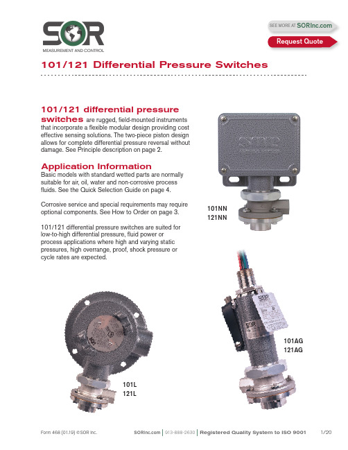
101/121 differential pressure switches are rugged, field-mounted instrumentsthat incorporate a flexible modular design providing cost effective sensing solutions. The two-piece piston design allows for complete differential pressure reversal without damage. See Principle description on page 2.Application InformationBasic models with standard wetted parts are normally suitable for air, oil, water and non-corrosive process fluids. See the Quick Selection Guide on page 4.Corrosive service and special requirements may require optional components. See How to Order on page 3.101/121 differential pressure switches are suited for low-to-high differential pressure, fluid power or process applications where high and varying static pressures, high overrange, proof, shock pressure or cycle rates are expected.101NN 121NN101AG 121AG101L 121L101/121 Differential Pressure SwitchesSEE MORE AT Request QuoteF h = Force, Hi Pressure F l = Force, Lo PressureF s = Force, Range SpringF d = Force, Resultant DifferentialF d = F h - (F l + F s )Process pressure is sensed by a diaphragm-piston combination. Hi-side system pressure acts on the piston to product force F h . It is counteracted by the adjustable range spring force F s and Lo-side system pressure acting on the backside of the piston to produce force F l . The resultant force F d acts on the piston and overcomes the force of the adjustable range spring [F d = F h – (F l + F s )] and moves a shaft that actuates (deactuates) an electrical switching element.AF hF lF sF dNCNOCDifferential Pressure SwitchPrincipleQuick Selection GuideBasic Series 101/121 differential pressure switches with standard wetted parts are normallysuitable for air, oil, water and non-corrosive processes. Refer to the Quick Selection Guide section on page 4. Corrosive service and particular customer requirements may require optionalcomponents. Refer to the How to Order section on this page or the dedicated page to locate optional components, such as: housings, switching elements, diaphragm systems, pressure ports and accessories. Each position in the model number, except Accessories, must have a designator.101NN-K3-N4-C1A-YYModel Number SystemSeriesHousingDiaphragm& O-RingSwitching Element Adjustable RangePressure PortAccessoriesApplicationsThe Series 101/121 differential pressure switches in this catalog are suitable for a wide variety of process and fluid power applications. Specific application requirements can normally be met by selecting optional components, such as, switching elements and diaphragm systems. Certain applications may require customized specials. Consult local representative or the factory.Weathertight, conventional explosion proof and hermetically sealed explosion proof models are presented in this catalog.How to OrderSteps 1 through 5 are required; Step 6 is optional. Orders must have complete model numbers, i.e. each component must have a designator.Order information must include:a) Set Point (increasing or decreasing)b) If decreasing Set Point, state from what greater Set Point is approached c) Normal system (static) pressureStep 1: Select Housing for type of service (pages 5 & 6).Step 2: Select electrical Switching Element for housing and electrical service (pages 6 & 7).Step 3: Select Adjustable Range according to Set Point (page 8).Step 4:Select Diaphragm and O-Ring for process compatibility and containment (page 9).Step 5:Select Pressure Port for process connection (page 9). Step 6: Select Accessories as required for service (page 10).If Agency Listed, Certified or Approved differential pressure switches are required, see page 11 for components that must be specified.Differential Pressure SwitchHow to OrderDifferential Pressure Switch Principle Specify model number from table below.WeathertightNEMA 4, 4X, IP65Hazardous LocationsClass I, Groups C & D;Class II, Groups E, F & G;Divisions 1 & 2Hazardous LocationsClass II, GroupsE, F & G; Divisions 1 & 2See Agency Listings page 11.See Switching Element Groups 1, 2, 3, 4 page 6.See Agency Listings page 11.See Switching Element Groups 1, 2, 3, 4 page 6.Contains UL Listed, CSA Certified, ATEX and SAA Approved Electrical: 1/2” NPT(M)-Top Material: See Switching Element Group 5 page 6.See Switching Element Groups 1, 2, 3, 4 page 6.See Agency Listings page 11.See Switching Element Groups 1, 2, 3, 4 page 6.Open bracket with exposed switchingelement does not meet NEMA 1.See Switching Element Groups 1 & 3 page 6.See Agency Listings page 11.See Switching Element Group 7 page 6.Weathertight —NEMA 4, 4X, IP65Electrical: 3/4” NPT(F)- Right Material: AluminumCover: heavy duty with Viton gasketN4See Agency Listings page 11.See Switching Element Groups 1, 2, 3, 4 page 6.See Switching Element Groups 1 & 3 page 6.RN RM Electrical-RT: 3/4” NPT(F)-Right Electrical-RS: M20 x 1.5-Right Six-place compression type terminal block Material: 316SSRT RSContains UL Listed, CSA Certified and SAA Approved hermetically sealed switching elements. Electrical: 3/4” NPT(F)-TopMaterial: Copper-free** aluminumWeathertight: NEMA 4/4XSee Switching Element Group 6 page 6.Class II, Groups E, F & G; Divisions 1 101NN -K3-N4-C1A-YYSeparate electrical and set point adjustment compartments. WeathertightSix-place compression type terminal blockSee Agency Listings page 11.Class II, Groups E, F & G; Divisions 1 & 2 as an outlet box only.Electrical: 3/4” NPT(F)-Left, Right, TopSix-place compression type terminal block with Optional LL Material: Copper-free** aluminum Class I, Groups A, B, C, D; Class II,See Switching Element Groups 1 & 3 page 6.*B3* Not recommended for direct mount where vibration is expected. Housing should be securely mounted to a flat surface (bulkhead or panel rack) or pipe stanchion. ** Consult the factory.See Switching Element Groups 1 & 3 page 6.See Switching Element Groups 1, 2, 3, 4 page 6.See Switching Element Groups 1 , 3, 7 page 6.See Switching Element Groups 1, 2, 3, 4, 7 page 6.Hazardous Locations — Conventional Explosion ProofATEX and SAA Approved Electrical: 1/2” NPT(M)-TopMaterial: See Switching Element Group 5 page 6.101NN-K3-N4-C1A-YYCross reference compatibility chart above to ensure that switching element will fit in housing.Notes1. AC/DC electrical ratings for switchingelements K, KK, KA, J, JJ, G, GG, A, AA, L, LL, E, EE, C, S, B, BB, Y, YY, W, T, H, D and M are UL Recognized and CSA Certifiedwith conditions and exceptions specified in Note 3.2. The hermetically sealed switching elementcapsule is UL Listed, CSA Certified, ATEXand TestSafe Approved as a snap switch in accordance with the following table withconditions and exceptions specified inNote 3.3. DC electrical ratings are for resistive loadsonly. DC ratings marked with an asterisk (*) are not agency recognized or certified buthave been verified by testing or experience.Switching Element101NN-K3-N4-C1A-YY 4. DPDT switching elements have wire leadsexcept when supplied in housings RN, RT,RM, RS, RB, B3, B4, B5, B6.5. Switching element minimum/maximumambient temperatures:-40 to 167o F (-40 to 75o C) AF, AG, EB,EF, EG, JB,JF, JG, JR, KB -65 to 400o F (-54 to 204o C) B, Y, W-65 to 250o F (-54 to 120o C) A, E, J-65 to 180o F (-54 to 80o C) All others 6. Dead band multipliers must be applied to thetypical dead band figures given in thespecification tables on page 8.7. Switching elements B, W and Y have anElgiloy spring. Experience indicates goodservice in atmospheres with corrosivegases - H2S, ammonia, etc.CAUTION: The switching element assembly has been precisely positioned in the housing at the factory for optimum performance. Any inadver-tent movement or replacement in the field will degrade performance, could render the device inoperative and may void the warranty unless factory authorized procedures are followed.Differential Pressure SwitchAdjustable Range101NN-K 3-N4-C1A-YYThis table lists designators for corresponding adjustable ranges, dead bands, maximum system pressure and maximum differential pressure. Adjustable range is expressed for increasing pressure: the Set Point must be within the adjustable range. Dead band is expressed as typical at mid-range. See dead band considerations at the bottom of this page.Notes1. Ambient temperature range: -30 to 180o F (-34 to 80o C). Check restrictions, page 7, for optional electrical switching elements and page 9 for optional diaphragm systems.2. Metric bar (mbar) values are practical equivalents of the mathematical conversions. This data appears on the product nameplate when metric engineering units are specified.3. CAUTION: When the process could be considered dirty in terms of suspended particles, it is recommended that 20-micron in-line filters be installed on the Hi and Lo pressure ports.4. To achieve optimum performance, the 101/121 should be calibrated under simulated system operating conditions.Dead Band Considerations1. Dead band values are expressed as typical expected at mid-adjustable range and 50% maximum system pressure (static pressure) using the standard K switching element.2. Dead bands are fixed (non-adjustable), except when T or H switching elements are used.3. A dead band multiplier must be applied to the typical dead band value shown in adjustable range above whenever an optional switching element is specified.4. Dead band can be widened by selecting an optional switching element with a multiplier greater than 1.0.5. Use of metal diaphragms may have additional impact on Dead band values. Contact thefactory for details.Differential Pressure SwitchExample: Model 101NN-G3-N4-C1ATypical Dead Band 0.7 psid G-Switching Element muliplier 2 Corrected Typical Dead Band0.7 x 2 = 1.4 psidDiaphragm & O-Ring101NN-K3-N4-C1A-YY Notes1. N4 diaphragm system is standard. It isnormally suitable for air, oil, water andnon-corrosive processes.2. Other diaphragm and o-ring combinationsmay be available. Consult the factory or the SOR representative in your area for more information.3. Wetted parts have been selected asrepresenting the most suitable commercially available material for use in the serviceintended. However, they do not constitute a guarantee against corrosion or permeation, since processes vary from plant to plant and concentration of harmful fluids, gases orsolids vary from time to time in a givenprocess. Empirical experience by usersshould be the final guide. Alternate materials based on this are generally available.4. Differential pressures exceeding 100 psidmay affect Set Point when M2, M4, or H4diaphragm and o-ring combination is used. 5. Dead bands are higher when using metaldiaphragm options. Consult the factory.6. This table shows allowable minimum andmaximum temperatures for o-rings.Step 5: Pressure Port101NN-K3-N4-C1A-YYNotes1. C1A pressure port is standard. It is normallysuitable for air, oil, water and non-corrosive processes.2. Other pressure port materials and connectionsizes may be available. Consult the factory or the SOR representative in your area for more information.Material & SystemsDifferential Pressure SwitchStep 6: Accessories101NN-K3-N4-C1A-YY101/121Differential Pressure SwitchAgency ListingsULCSAATEX/ IECEx orINMETRODifferential Pressure SwitchManual Reset101RB -D 3-N4-C1A-YYSeries 101/121 Differential Pressure Switches in this catalog may be specified with manual reset electrical switching elements D or M.D actuates automatically on increasing pressure. M actuates automatically on decreasingpressure. Depress the button, covered by the weathertight boot to manually reset. Housings must be RB weathertight or S explosion proof because of the requirement of a hub for themanual reset assembly. Refer to page 3 for order instructions.Approximate WeightsActual shipping weights may vary from the charted values because of product material,configuration and packaging requirements.RB-WeathertightS-Explosion ProofDifferential Pressure SwitchSOR recognizes that there is no industry convention with respect to terminology and definitions pertinent to pressure switches. This glossary applies to SOR Pressure Switches.Adjustable RangeThe span of pressure between upper and lower limits within which the pressure switch may be adjusted to actuate/deactuate. It is expressed for increasing differential pressure.Dead BandThe difference in pressure between the increasing Set Point and the decreasing Set Point. It is expressed as “typical,” which is an average with the increasing Set Point at mid- adjustable range for a pressure switch with the standard K switching element. It is normally fixed (nonadjustable).Differential Pressure SwitchA bi-stable electromechanical device that actuates/deactuates one or more electrical switching element(s) at a predetermined discrete differential pressure (Set Point) upon rising or falling differential pressure.DPDT Switching ElementDPDT is two synchronized SPDT switching elements that actuate together at increasing Set Point and deactuate together at decreasing Set Point. Discrete SPDT switching elements allow two independent circuits to be switched; i.e., one AC and one DC.The synchronization linkage is factory set, and is not field adjustable. Synchronization is verified by connecting test lamps to the switching elements and observing them go “On” simultaneously at actuation and “Off” simultaneously at deactuationHermetically SealedA welded steel capsule with glass-to-metal, factory-sealed, electrical leads that isolatesthe electrical switching element(s) from the environment.Maximum Differential PressureThe maximum difference in pressure that may be continuously applied between the Hi and Lo (Lo and Hi) pressure ports without causing permanent change of Set Point, leakage or material failure.OverrangeThe maximum input pressure that may be continuously applied to the pressure switch without causing permanent change of Set Point, leakage or material failure.Proof PressureThe maximum input pressure that may be continuously applied to the pressure switch without causing leakage or catastrophic material failure. Permanent change of Set Points may occur, or the device may be rendered inoperative.RepeatabilityThe ability of a pressure switch to successively operate at a Set Point that is approached from a starting point in the same direction and returns to the starting point over three consecutive cycles to establish a pressure profile. The closeness of the measured Set Point values is normally expressed as a percentage of full scale (maximum adjustable range pressure).Set PointThat discrete pressure at which the pressure switch is adjusted to actuate/deactuate on rising or falling pressure. It must fall within the adjustable range and be called out as increasing or decreasing differential pressure. SPDT Switching ElementSingle-Pole, Double Throw (SPDT) has three connections: C — Common, NO — Normally Open and NC — Normally Closed, which allows the switching element to be electrically connected to the circuit in either NO or NC state.Glossary of T ermsDifferential Pressure Switch6.40.25 MIN TO 76.23.00 MAX3/4 NPT(F)(STD)1/2 NPT(F)(OPT)7.10.281/4 NPT(F) HI SIDE1/4 NPT(F) LO SIDEDimensions in this catalog are for reference only. They may be changed without notice. Contact the factory for certified drawings for a particular model number. Dimensions are expressed as millimeters over inches (Linear = mm/in.)Housing: Weathertight - Nonhazardous Service (NEMA 4, 4X IP65)Housing: NN, N3, N4Dimensions in this catalog are for reference only. They may be changed without notice. Contact the factory for certified drawings for a particular model number. Dimensions are expressed as millimeters over inches (Linear = mm/in.)Housing: RB Manual ResetWeathertight - Non-hazardous Service (NEMA 4, 4X IP65)Drawing 00906046.40.25 MIN TO 76.23.00 MAX Dimensions in this catalog are for reference only. They may be changed without notice. Contact the factory for certified drawings for a particular model number. Dimensions are expressed as millimeters over inches (Linear = mm/in.)Housing: H3 Open BracketGeneral Purpose - Non-hazardous ServiceHousing: PP, P3 NEMA 1Drawing 0090601Dimensions in this catalog are for reference only. They may be changed without notice. Contact the factory for certified drawings for a particular model number. Dimensions are expressed as millimeters over inches (Linear = mm/in.)Housing: LHousing: LCConventional Explosion Proof - Hazardous ServiceClass I, Group C, D; Class II, Group E, F, G: Divisions 1 & 2Drawing 0090606Housing: SCDimensions in this catalog are for reference only. They may be changed without notice. Contact the factory for certified drawings for a particular model number. Dimensions are expressed as millimeters over inches (Linear = mm/in.)Conventional Explosion Proof - Hazardous ServiceClass I, Group C, D; Class II, Group E, F, G: Divisions 1 & 2Conventional Explosion Proof - Hazardous ServiceClass I, Groups C, D; Class II, Groups E, F, G: Divisions 1 & 2Housing: B3, B4, B5, B6Class I, Groups B, C, D; Class II, Groups E, F, G; Divisions 1 & 2Housing: T AClass I, Groups A, B, C, D; Class II, Groups E, F, G; Divisions 1 & 2Dimensions in this catalog are for reference only. They may be changed without notice. Contact the factory for certified drawings for a particular model number. Dimensions are expressed as millimeters over inches (Linear = mm/in.).Drawing 0090610PROCESS CONNECTION CONNECTION OPTIONALDrawing 0090611PROCESS CONNECTIONPRODUCT CERTIFICATION DRAWING ALL DIMENSIONS ARE ±1/16 IN UNLESS OTHERWISE SPECIFIEDMMLINEAR =INK MITCHELLM SMITHS BOAL14 SEP 2011DIMENSION DRAWING 101/121 BA EO NUMBER: 5095SCALE: 0.7000906125SHEET 1 OF 1BMODEL #SALES ORDER #LINE ITEM #PURCHASE ORDER #SALES PAGEPROCESS CONN SIZE LENGTH A 1/4 NPTM SHOWN 29.71.171/2 NPTF37.61.481/2 NPTM 34.81.373/4 NPTF 39.91.5741.6ADDFOR M20 X 1.5 F 1.64ELECTRICAL CONNECTION6.40.25457.218.00Hermetically Sealed Explosion Proof - Hazardous ServiceClass I, Groups A, B, C, D; Class II, Groups E, F, G; Divisions 1 & 2Housing: BAHousing: AG, AH Dimensions in this catalog are for reference only. They may be changed without notice. Contact the factory for certified drawings for a particular model number. Dimensions are expressed as millimeters over inches (Linear = mm/in.)Drawing 0090612Drawing 0091067。
ISO121芯片电路

电磁兼容性(EMC)考虑因素
01
在ISO121芯片电路设计中,应充分考虑电磁兼容性因素,以降低系 统对外部环境的电磁干扰和提高系统自身的抗干扰能力。
02
合理选择元器件的封装形式和布局方式,以减少电磁辐射和传导干扰 。
解决关键技术难题,提高电路稳定性
在项目实施过程中,我们成功解决了多项关键技术难题,有效提高了ISO121芯片电路 的稳定性和可靠性。
对未来研究的建议和展望
深入研究ISO121芯片电路的优化设计
针对现有电路存在的不足,建议未来研究进一步关注优化设计,提高电路性能和降低成本 。
探索新的应用领域和市场前景
03
对于关键信号线,应采用差分传输、屏蔽等措施,以降低信号传输过 程中的电磁辐射和串扰。
04
在PCB设计时,应注意地线布局和电源滤波等处理措施,以提高系统 的电磁兼容性。
03
ISO121芯片电路调试与 测试
调试流程与步骤
电源及地线检查
确保电源和地线连接正 确,无短路或断路现象
。
信号线连接检查
检查所有信号线是否按 照电路图正确连接。
01
02
03
04
隔离电压
ISO121芯片的隔离电压可达 数千伏,确保在恶劣环境下信
号的稳定传输。
线性度误差
该芯片的线性度误差极低,可 保证信号传输的准确性。
带宽
ISO121芯片具有较宽的带宽 ,适用于高速信号传输的应用
场景。
工作温度范围
该芯片可在宽工作温度范围内 正常工作,适应各种恶劣环境
。
02
ADC121C021资料
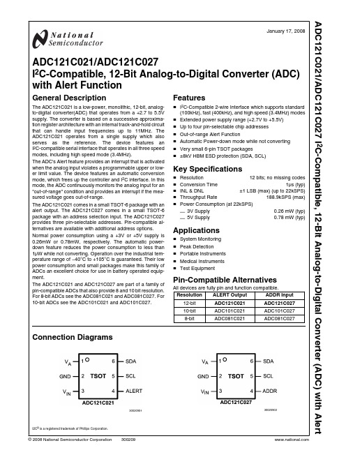
Key Specifications
■ Resolution
12 bits; no missing codes
■ Conversion Time
1µs (typ)
■ INL & DNL
±1 LSB (max) (up to 22kSPS)
■ Throughput Rate
188.9kSPS (max)
Block Diagram
Package TSOT-6 TSOT-6 Tape-and-Reel TSOT-6 TSOT-6 Tape-and-Reel
Evaluation Board
Top Mark X30C X30C X31C X31C
30020903
2
ADC121C021/ADC121C027
Normal power consumption using a +3V or +5V supply is 0.26mW or 0.78mW, respectively. The automatic powerdown feature reduces the power consumption to less than 1µW while not converting. Operation over the industrial temperature range of −40°C to +105°C is guaranteed. Their low power consumption and small packages make this family of ADCs an excellent choice for use in battery operated equipment.
PCA-121C1W资料

INSTALATION, OPERATION & MAINTENANCEMANUALFORPA-1001A SeriesSIGNAL CONDITIONER& CONVERTORSSIGNAL CONDITIONER &CONVERTERSPA1001A SeriesINTRODUCTION:The PA1001A series preamplifiers/signal conditioners and converters are suitable for use with either magnetic or RF type pickup coils and allow convenient interfacing with process measuring devices and digital electronics.When used with Magnetic type pickups they accept low level signals and produces a pulse output, while providing rejection of unwanted noise and false signals.A RF type pickup reduces the pickup drag associated with conventional magnetic pickups,resulting in a significant increase in the usable range. The PA1001A series excite a RF type pickup with a 20KHz signal. Motion of ferrous material is sensed and the motion modulates the coil field and subsequent conditioning provides a pulse output signal.The output signal of the PA1001A series have a square pulse wave form, each pulserepresentative of an actuator (rotor blade, gear tooth, turbine blade, etc.) passing by the sensing area of the pickup.Four output signal options are available:compatiblei. TTL/CMOScollectorii. Openiii. 0 to 10VDC square wave andiv. A square wave that is tied to the input power.The unit is powered by a user supplied 8 to 30 VDC filtered power supply. An on-board regulator provides the required regulation and noise rejection.Optional features include factory installed pulse scaling and field installable plug in modules for Analog output. Pulse scaling provides the user with scaling options of ÷2, ÷4, ÷8, ÷16, ÷32, ÷64, or ÷128, which is useful when a remote device has a maximum count speed that is less than the pulse-generating device. Analog output provides a current and voltageoutputs proportional to RPM, flow rate etc.CHARACTERISTICS AND SPECIFICATIONS:POWER INPUT:•Voltage: 8-30 VDC•Current Draw: 125mA @ 24VDC, with all options equipped.•Reverse polarity protectedPICKUP INPUT:RF Pickup:•Modulation Carrier Frequency: 20KHz•Input Frequency: 2 Hz to 5KHz, adjustable trigger level•Trigger Sensitivity: 20 millivolt peak to peak (minimum)•Carrier Adjustment: to allow precise tuning of carrier signal to physical environment (e.g. air gap, wall thickness)•Maximum Air Gap: 0.160”•Preferred Coil Inductance: 1.0 milliHenry +/- 10%•Maximum Distance From Pickup To Preamplifier 100 feetMagnetic Pickup:• Input protected, RF and band pass filtered•Input Frequency: 0 to 10KHz, adjustable trigger level•Trigger Sensitivity: 4 millivolt RMS (minimum)NOTE: At 4mV frequency range 10 Hz to 3KHz•Input Impedance: 40K Ohms (nominal)•Maximum Input Signal: 600 Volts RMS•Maximum Distance From Pickup To Preamp: 100 feetPULSE OUTPUTS:•TTL/CMOS (Standard); Fan-out of 5 TTL/CMOS loadsOFF state voltage 30 VDCMaximum• Open Collector:Maximum ON current 0.40 amps•0 to 10 VDC square wave•Square wave tied to input voltage•Pulse scaling (option): ÷2, ÷4, ÷8, ÷16, ÷32, ÷64, or ÷128 user selectable.CURRENT OUTPUT OPTION:•Accuracy +/- 0.05% of full-scale +/-200 PPM/°C.•Available range 4 to 20mA.•Output suitable for driving floating or grounded loads.•Maximum loop impedance 500 ohms.•Response time 0.3 seconds for 10 to 90 %.VOLTAGE OUTPUT OPTION:•Accuracy +/- 0.05% of full-scale +/-200 PPM/°C.•Available range 0 to 5VDC or 0 to 10VDC, user selectable.•Impedance less than 10 ohms.•Response time 0.3 seconds for 10 to 90 %.ENVIRONMENTAL:•OPERATING: -40°C TO 85°C•STORAGE: -40°C TO 150°CENCLOSURES:•Unit is intended for mounting in a conduit box and comes with 2 ½” on center mounting holes. An optional explosion proof or NEMA-4x enclosure is available upon request.APPROVALS:•EN50081-1:1992 Generic Emission Standard•EN50082-2:1995 Generic Immunity Requirements•CE compliant to EMC Directive 89/336/EECfor uses in residential, commercial, light or heavy industrial environments.INSTALLATION AND WIRING DETAILS:In considering the interconnections between the PA1001A and the measurement system someattention must be given to anticipated noise sources and to the coupling of these noise sources to the interconnecting wiring.Noise signals may be coupled into the wiring between the pickup coil, the PA1001A, and theelectronic measuring systems. In general, utilizing a shielded, twisted pair for the interconnection greatly reduces this coupling. The shield should be grounded on both ends of the cable.However, even with proper interconnecting cabling, cross talk with other signal lines or power lines may still occur and should be avoided. Physical isolation of the wiring reduces the chance ofpotential problems.The pickup coil should not be located more than 100 feet from the PA1001A preamplifier. It isrecommended that the PA1001A be installed on or near the pickup coil to assure optimumperformance.INSTALLATION:The Model PA1001A should be placed in a convenient location that maintains access to the unit should repairs or readjustment is required.Connections to the terminal block should be carefully dressed to avoid having bare wires extend pass the screw clamp on the terminal block. This is particularly important when the PC card is mounted within an explosion proof enclosure. Wires should be neatly dressed near bottom of enclosure to prevent problems when cover is installed.For compliance with EMI/RFI requirements the pre-amplifier must be installed in a metal enclosure such as a suitable NEMA 4 (e.g. GUAC) junction box. The enclosure must be properly grounded.Also a grounding strap is required from the enclosure to the power supply common (pin 7).The cable entry requires 360° grounding coverage to the enclosure case. This is obtained by using twisted pair with full braid cable and a cable fitting that provides a metal to metal cable clamping connection. The insulation of the cables should be stripped back to allow for connection to theterminal block and allow for the cable fitting to clamp onto the braided shield. Any open areas should then be covered using foil tape.In hazardous locations where metal conduit is used, 360° grounding are achieved. All cable shields should be terminated to the enclosure-grounding stud.Wiring For RF Pickup Coil:1. Connect a two conductor shielded cable from the pickup to Terminals 5 and 6. Connect theshield to Terminal 4 (see Figure 1). NOTE: It is also preferable that the pickup coil be grounded to the shield.2. Connect a power source, which must be within 8-30 VDC, to Terminals 7 and 8. The Plusvoltage is connected to Terminal 8 and the Return to Terminal 7 (see Figure 1).3. Connect the Pulse output wire to Terminal 3, and connect the Pulse common to Terminal 4 (seeFigure 1).4. Set Jumper HD2 (see Figure 3) to the RF position.5. Configure Jumper HD1 (see Figure 3) to the desired pulse output as follows:Pulse Output Type HD1 Jumper ConfigurationOpen Collector JP2Square Wave to Vin JP1 and JP2TTL/CMOS JP1, JP2 and JP30-10 VDC Square Wave JP1, JP2 and JP46. Install pickup (e.g. in meter) and provide power to PA1001A. Use a digital voltmeter set to DCvoltage and attach the positive lead to Terminal 6 and the common lead to Terminal 2. Adjust the Carrier Adjustment (R2) (see Figure 3) to a reading of 3.00 VDC to fine-tune the pickup for airgap, wall thickness, etc.7. With power still supplied to PA1001A determine if pulse output is being generated in the absenceof motion. Adjust the RF Trigger (R24) (see Figure 3) clock wise until the false pulsation hasstopped. If pulsation continues when adjusted fully clock wise, check that all shields have beenproperly terminated and grounded.Wiring For Magnetic Pickup Coil:1. Connect a two conductor shielded cable from the pickup to Terminals 1 and2. Connect theshield to Terminal 4 (see Figure 2). NOTE: It is also preferable that the pickup coil be grounded to the shield.2. Connect a power source, which must be within 8-30 VDC, to Terminals 7 and 8. The Plusvoltage is connected to Terminal 8 and the Return to Terminal 7(see Figure 2).3. Connect the Pulse output wire to Terminal 3, and connect the Pulse common to Terminal 4 (seeFigure 2).4. Set Jumper HD2 (see Figure 3) to the MAG position.5. Configure Jumper HD1 (see Figure 3) to the desired pulse output as follows:Pulse Output Type HD1 Jumper ConfigurationOpen Collector JP2Square Wave to Vin JP1 and JP2TTL/CMOS JP1, JP2 and JP30-10 VDC Square Wave JP1, JP2 and JP45.Install pickup (e.g. in meter) and provide power to PA1001A. Determine if pulse outputis being generated in the absence of motion. Adjust the MAG Trigger (R19) (see Figure3) clock wise until the false pulsation has stopped.Analog Output Option:1. For current output, wire two conductor, shielded cable to terminals 2 (common) and 3 (currentoutput).2. For voltage output, wire two conductor, shielded cable to terminals 2 (common) and 1 (voltageoutput).CONTROLS AND ADJUSTMENTS:STANDARD PRE-AMPLIFIER ADJUSTMENTS:CARRIER ADJUSTMENT: A twenty turn control used to precisely tune the specific sensingdepth, wall thickness, material type, air gap,etc. of the RF pickup coil.TRIGGER: A twenty turn control used to set the trigger level of theRFRF coil input above the ambient noise level.MAG TRIGGER: A twenty turn control used to set the trigger level of theMagnetic coil input above the ambient noise level.COIL SELECTION: A two-position jumper that is used to select the desiredpickup coils to be used as the input.Input Coil Type HD2 SettingRF RFMagnetic MAGLIN\RAW PULSE: A two-position jumper that is used to select the desiredtrain.PulsePulse Type JP1 SettingRaw pulse train RAWLINLinearized pulse train(NOT AVAILABLE YET)PULSE SELECTION: A four-position jumper that is used to select theDesired type of pulse output.Pulse Output Type HD1 Jumper SettingsOpen Collector JP2Square Wave to Vin JP1 and JP2TTL/CMOS JP1, JP2 and JP30-10 VDC Square Wave JP1, JP2 and JP4PULSE SCALING ADJUSTMENTS:PULSE SCALER: A 8 position jumper header located on PA1001 circuit board which isused in programming the desired pulse output scaling (Division of 1,2, 4, 8, 16, 32, 64, or 128). Factory set with division of 1 as standard.ANALOG OUTPUT ADJUSTMENTS (PCA-121):20mA ADJ A twenty turn adjustment which is used to set current output to thedesired span corresponding to the equivalent full scale range. (i.e.20 mA at 100 RPM).4mA ADJ A twenty-turn adjustment that is used to set the current output signalto the desired zero value. (i.e. 4mA at zero RPM).V FS ADJ A twenty-turn adjustment that is used to set the voltage output to thedesired span corresponding to the equivalent full scale range. (i.e.5VDC or 10 VDC at 100 RPM).V O ADJ A twenty-turn adjustment that is used to set the voltage output signalto the desired zero value. (i.e. 0 VDC at zero RPM).COARSE RANGE ADJ A dual in line DIP switch which is located on the PCA-121 board,which is used to perform a coarse range adjustment for the inputfrequency range.V FS SELECTION A two position jumper (JP1) that is used to select the desired voltageoutput range of either 0 to 5VDC or 0 to 10VDC.CALIBRATION PROCEDURE:In order to perform field calibration and troubleshoot the PA1001A, the following equipments are recommended.MANUFACTURER PART NUMBER DESCRIPTION Fluke 8060A True RMS MultimeterTopward 8112 Digital Function GeneratorViz WD-755 Multi Function CounterTool Spectrol8-TOOO Adjustment Table - 1(Coarse Range Adjustment):Frequency Range SwitchPosition50 to 100Hz 1100 to 200Hz 2200 to 400Hz 3400 to 800Hz 4800 to 1600Hz 51600 to 3200Hz 63200 to 6400Hz 76400 to 12800Hz 8FOR CURRENT OUTPUT:•Connect a digital milliampmeter or equivalent, across the current output terminals.•On the PCA-121 select the “Coarse Range Adj” that corresponds to the maximum input frequency. Refer to Table - 1 for selection options.•Adjust “4mA ADJ” control for desired “Zero” current (i.e. 4mA).•Inject the full-scale test frequency while adjusting “20mA ADJ” for current equal to SET (SPAN).•Iterate above steps until no change is observed.FOR VOLTAGE OUTPUT:NOTE: For proper adjustment of the voltage-output, FirstPerform calibration of the current output.•Connect a digital voltmeter across the voltage output terminals.•On the PCA-121 select the “Coarse Range Adj” that corresponds to the maximum input frequency. Refer to Table -1 for selection options.• Adjust “V O ADJ” for 0.00 volts).•Inject the test frequency while adjusting “V FS ADJ” for voltage equal to SET (SPAN).•Iterate above steps until no change is observed.Control and Adjustment Detail for the PCA-121元器件交易网Ordering InformationPA-1001A IA B 1 w1 = 24 VDC (8 to 30 VDC)2 = 110 VAC 50/60 Hz3 = 220 VAC 50/60 HzPA1001A – 7/02 Page 11 of 11。
CSC-121说明书
第一篇装置的技术说明1概述1.1 适用范围CSC-121A数字式综合重合闸及断路器辅助保护装置(以下简称装置或产品)是由单片机实现的数字式保护装置,主要适用于220kV及以上电压等级的一个半断路器接线方式。
装置包括综合重合闸、失灵保护、死区保护、充电保护、三相不一致保护等功能元件,可以满足一个半断路器接线中综合重合闸和断路器辅助保护按断路器装设的要求。
对于一个半断路器接线方式,无论是中间断路器还是边断路器,装置的软硬件都是相同的。
2.10 装置主要功能装置具有以下功能:a) 综合重合闸功能。
装置提供单相重合闸、三相重合闸、综合重合闸、重合闸停用四种方式可选。
可接入断路器两侧的启动重合闸回路,满足一个半断路器中间断路器的要求,且边断路器和中间断路器软硬件相同,为现场使用提供了方便;b) 失灵保护。
失灵启动提供了三级跳闸逻辑,即瞬时重跳本断路器,线路保护单跳未断开开关延时三跳本断路器,开关失灵延时跳相关断路器;除相过流开放失灵保护外,并提供了负序电流、零序电流开放失灵保护,满足反措中关于发变组失灵保护的要求;c)死区保护。
为TA与开关之间的保护死区专门设计的保护元件;d) 三相不一致保护,由三相不一致开入启动,可经零序电流、负序电流、跳位等元件开放。
e) 充电保护,线路投运或失去保护时投入的过流保护,设两段,可分别投退,并可设置手合充电短时投入或长期投入。
2.11 装置主要技术参数2.11.1额定参数a) 直流电压:220V或110V(按订货要求);b) 交流电压:检同期电压:100V或100/3V;c) 交流电流:5A或1A(按订货要求);d)频率:50Hz。
2.11.2 整定范围装置整定范围见定值清单。
2.11.3 动作值误差a) 电流动作值误差不超过±3%;b) 电压动作值误差不超过±1V;c)延时段动作值误差不超过±25ms。
2.11.4 精确工作范围交流采样的精确工作范围:电压回路 1V~100V(有效值);电流回路0.1In~30In(有效值);3 功能原理说明3.1 保护程序整体结构保护CPU软件包括主程序、采样中断程序和故障处理中断程序。
CSC-121A
目次1范围 (3)2本指导书涉及的技术资料和图纸 (3)3安全措施 (3)4备品备件清单 (3)5修前准备 (4)6检修工序及质量标准 (5)7检修记录 (20)8设备试运、调试、试验 (26)9不符合项通知单 (26)10完工报告单 (27)11质量签证单 (29)1范围本指导书适用于750KV系统CSC-121A断路器保护装置、JFZ分相操作箱及二次回路检修工作。
2本指导书涉及的技术资料和图纸下列文件中的条款通过本规范的引用而成为本规范的条款。
凡是注日期的引用文件,其随后所有的修改单或修订版均不适用于本规范,然而,鼓励根据本规范达成协议的各方研究是否可使用这些文件的最新版本。
凡是不注日期的引用文件,其最新版本适用于本规范。
DLT 995-2006 继电保护及电网安全自动装置检验规程DL 400-91 继电保护和安全自动装置技术规程DL 478-92 静态继电保护及安全自动装置通用技术条件继电保护和电网安全自动装置现场工作保安规定电力系统继电保护及安全自动装置反事故措施管理规定北京四方CSC-121A数字综合重合闸及断路器辅助保护装置说明书JFZ分相操作箱技术说明书CSC-121A保护装置原理图交流采样规程3安全措施□严格执行《电业安全工作规程》3.1准备工作中需要注意的事项□工作票所列安全措施已正确执行完毕。
□电气一次系统停运并转检修状态(各侧开关已断开,在检修位置,各开关的控制电源、信号电源已断开,检修工作票已办理工作手续。
□清点所有专用工具齐全,检查合适,试验可靠。
□现场工具、零部件放置有序。
□使用的试验仪器、仪表已经过检验并合格。
□参加检修的人员必须熟悉本作业指导书,并能熟记熟背本书的检修项目,工艺质量标准等。
□参加本检修项目的人员必需安全持证上岗,并熟记本作业指导书的安全技术措施。
□开工前召开专题会,对各检修参加人员进行组内分工,并且进行安全、技术交底。
□所有在场的工作人员必须保持良好的精神状态。
优化严重冠状动脉钙化病变的介入治疗策略

优化严重冠状动脉钙化病变的介入治疗策略沈卫峰;张瑞岩【期刊名称】《中国介入心脏病学杂志》【年(卷),期】2017(025)012【总页数】3页(P661-663)【关键词】冠状动脉钙化病变;介入治疗【作者】沈卫峰;张瑞岩【作者单位】200025 上海,上海交通大学医学院附属瑞金医院心内科;200025 上海,上海交通大学医学院附属瑞金医院心内科【正文语种】中文【中图分类】R541.4过去的30多年中,我国的经皮冠状动脉介入治疗(percutaneous coronary intervention,PCI)迅猛发展。
2016年,全国PCI病例数超过66万,经桡动脉入径广泛使用,各种介入操作和相关影像学技术蓬勃开展[1]。
然而,随着我国人口逐渐老龄化,高危和复杂冠状动脉病变(例如左主干、分叉、慢性完全闭塞病变等)越来越多见。
严重冠状动脉钙化病变的介入治疗仍具挑战性[2-4]。
且PCI患者常存在较多的内科合并症,故而血运重建的决策需多学科的通力协作,以提高整体临床疗效[5-6]。
在本期《中国介入心脏病学杂志》中,温尚煜教授及其团队总结了2000年1月至2016年10月大庆油田总医院连续248例严重冠状动脉钙化病变患者旋磨术并发症的防治以及关键操作技术[7]。
尽管这些经验来自单中心,却仍值得国内同行们借鉴。
显然,PCI术前冠状动脉病变钙化程度的严格评估、术中介入治疗策略的正确选择以及围术期并发症的及时防治,是优化严重冠状动脉钙化病变介入治疗的关键。
1 如何评估与介入操作相关的冠状动脉钙化病变的严重性在X线透视下清晰可见的冠状动脉钙化,大多为老年退行性冠状动脉Monckeberg钙化(中层钙化)。
但是,真正引起介入操作和支架置入困难的主要是严重冠状动脉内膜钙化(斑块钙化),尤其是当钙化累及范围>270°或整个血管圆周时,冠状动脉造影对此很难识别。
虽然无创性冠状动脉CT造影(CTA)对检出冠状动脉钙化较为敏感,但对内膜钙化的判断尚存在严重不足[8]。
- 1、下载文档前请自行甄别文档内容的完整性,平台不提供额外的编辑、内容补充、找答案等附加服务。
- 2、"仅部分预览"的文档,不可在线预览部分如存在完整性等问题,可反馈申请退款(可完整预览的文档不适用该条件!)。
- 3、如文档侵犯您的权益,请联系客服反馈,我们会尽快为您处理(人工客服工作时间:9:00-18:30)。
Distributor: Electro-Stock Tel: 630-682-1542 Fax: 630-682-1562
FEATURES:
• Large switching capacity up to 80A • Small size and light weight
• PCB pin and quick connect mounting available • Suitable for automobile and lamp accessories
• QS-9000, ISO-9002 Certified Manufacturing
28.5 x 28.5 x 26.5 (40.0) mm
CONTACT DATA
Contact Arrangement
1A = SPST N.O. 1B = SPST N.C. 1C = SPDT
1U = SPST N.O. (2 terminals) Contact Configuration Standard
Heavy Duty Contact Rating
1A 1B 1C 1U 60A @ 14VDC 40A @ 14VDC 60A @ 14VDC N.O. 40A @ 14VDC N.C. 2x25A @ 14VDC
80A @ 14VDC 70A @ 14VDC 80A @ 14VDC N.O. 70A @ 14VDC N.C. 2x25A @ 14VDC
Contact Resistance < 30 milliohms initial Contact Material
AgSnO 2In 2O 3 Maximum Switching Power 980W Maximum Switching Voltage 75VDC Maximum Switching Current 80A
COIL DATA
Coil Voltage
VDC
Coil Resistance
Ω ± 10%
Rated Max.
1.8W Pick Up Voltage VDC (max)
75%
of rated voltage
Release Voltage VDC (min)
10%
of rated voltage
Coil Power
W
Operate Time
ms
Release Time
ms
6 7.8 20 4.2 0.6 12 15.6 80 8.4 1.2 24 31.2
320
16.8 2.4
1.8 7 5
CAUTION:
1. The use of any coil voltage less than the rated coil voltage may compromise the operation of the relay.
2. Pickup and release voltages are for test purposes only and are not to be used as design criteria.
GENERAL DATA
Electrical Life @ rated load Mechanical Life 100K cycles, typical 10M cycles, typical Insulation Resistance 100M Ω min @ 500VDC Dielectric Strength, Coil to Contact Contact to Contact 500V rms min. @ sea level 500V rms min. @ sea level Shock Resistance 147m/s 2 for 11ms Vibration Resistance 1.5mm double amplitude 10-40Hz Terminal (Copper Alloy) Strength 8N (Quick Connect), 4N (PCB Pins) Operating Temperature Storage Temperature -40 °C to + 85 °C -40 °C to + 155 °C Solderability 230 °C ± 2 °C for 10 ± 0.5s
Weight 46g
Distributor: Electro-Stock Tel: 630-682-1542 Fax: 630-682-1562
ORDERING INFORMATION
1. Series:
24VDC
CTA3 standard
CTA3F with mounting flange
CTA3M with metal bracket CTA3F 2.Contact Arrangement: 1A = SPST N.O. 1B = SPST N.C. 1C = SPDT
1U = SPST N.O. **Only available with standard contacts 1C
3. Sealing Options: S = Sealed C = Dust Cover
S 4. Termination Options: P = PCB Pins
Q = Quick Connect P 5. Coil Voltage: 6VDC 12VDC 24VDC
2 6. Contacts: 1 = Standard 2 = Heavy Duty 7: Coil Suppression: Blank = Standard
D = Diode (1N4005) Cathode on “86” terminal R = Resistor (680 Ohms) 2D = 2 diodes (1N4005)
DR = Diode & Resistor (1N4005 & 680 Ohms) Cathode on “86” terminal ** Consult factory if other values are needed.
DIMENSIONS – CTA3 (Units = mm)
Standard contacts (1) with PC Pins
Standard contacts (1) with Quick Connects
Heavy duty contacts (2) with PC Pins
Heavy duty contacts (2) with Quick Connects
Distributor: Electro-Stock Tel: 630-682-1542 Fax: 630-682-1562
DIMENSIONS – CTA3F (Units = mm)
Standard contacts (1) with Quick Connects Heavy duty contacts (2) with Quick Connects DIMENSIONS – CTA3M (Units = mm)
Standard contacts (1) with Quick Connects Heavy duty contacts (2) with Quick Connects SCHEMATICS, PC PIN DIMENSIONS, & PC LAYOUTS (BOTTOM VIEWS)
1A 1B
1C 1U。
