CTCDRH3D16F-220N中文资料
HSV-16系列全数控伺服说明书
通过修改伺服驱动器参数 可对伺服驱动器系统的工 作方式 内部参数进行修改 以适应不同应用环境和要求 2 状态显示齐全
HSV-16 设置了一系列状态显示信息 方便客户在调 试 运用过程中浏览伺服驱动器的相关状态参数 同时也 提供了一系列的故障诊断信息 3 宽调速比 与电机及反馈元件有关
版板所有 2002 武汉华中数控股份有限公司
1- 6
概述
第二章 概 述
HSV-16 是武汉华中数控股份有限公司继 HSV-9 型 HSV-11 型之后 推出的一款全数字交流伺服驱动器 该驱动器具有结构 小巧 使用方便 可靠性高等特点
2.1 产品简介
HSV-16 采用最新专用运动控制 DSP 大规模现场可编程逻辑 阵列 FPGA 和智能化功率模块 IPM 等当今最新技术设计 操作简单 可靠性高 体积小巧 易于安装
在正确安装 接线之前请认真阅读此使用手册 在操作之前必须 了解此设备安全信息 安全警告以及此设备的使用知识
1.1 与安全有关的符号说明
危险
错误使用时 会引起危险情况 可能会导致人身伤亡
注意
错误使用时 会引起危险情况 可能会导致人身轻度或中度伤亡 和设备损坏
版板所有 2002 武汉华中数控股份有限公司
1.1NM 到 42NM 1200RPM 1500RPM 2000RPM
额定转速 A 12 00 RPM B 1500RPM C 2000RPM F:3000RPM
冷却方式 A 自然冷却 B 强迫冷却 电机极数 4 4 极 6 6 极 8 8 极
电机规格代码 中心高 用中心高除以 10 的整数部分表示 GK6 系列交流伺服电动机
GK6 交流永磁同步伺服电机简介 GK6 系列交流伺服电动机与伺服驱动装置配套后构成的相互协调的系统 可广泛应用于机床 纺织 印刷 建材 雷达 火炮等领域 该电机采用自冷式 防护等级为 IP64-IP67 GK6 电机是永磁三相交流同 步电动机 采用高性能稀土永磁材料形成气隙磁场 由脉宽调制变频器控制 运行 具有良好的力矩性能和宽广的调速范围 电机带有装于定子绕组内的
施奈德EOCR保护器新产品中文版
Emission
& 7
i3DM / iFDM, i3MZ/iFMZ, i3MS/iFMS, i3M420/iFM420, i3BZ/iFBZ
0.5~60A, 60A ,
i3MS/iFMS 0.5~20A, 20A ,
& TCC 0.5~32A, 32A
i3BZ iFBZ
2
0.5A
D-time O-time
3BZ2 / FBZ2 AC/DC 100~240V
DC/AC 24V 50/60 Hz
i3DM / iFD AC/DC 100~2
DC/AC 24 50/60 Hz
A, F, H
5 Digit 7 Segment -
/ 3DD, 3DE, 3DM FD, FDE, FDM
-
5 Digit 7 Segment -
DC/AC 24V 50/60 Hz
i3MZ / iFMZ AC/DC 100~240V
DC/AC 24V 50/60 Hz
i3BZ / iFBZ AC/DC 100~240V
DC/AC 24V 50/60 Hz
i3M420 / iFM420 AC/DC 100~240V
DC/AC 24V 50/60 Hz
EOCR-iFDM (Z, S, 420) Window type
EOCR-iFDM (Z, S, 420, BZ) Bottom hole type
EOCR-i3DM (Z, S, 420, BZ) Terminal type
EOCR-iFDM (Z, S, 420, BZ) Terminal type
IEC61000-4-2 IEC61000-4-3 IEC61000-4-6 IEC61000-4-4 IEC61000-4-5 CISPR11
R316中文资料
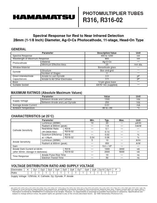
GENERALParameterDescription/ValueUnit Spectral ResponseWavelength of Maximum ResponsePhotocathodeWindow MaterialDynodeDirect Interelectrode Capacitances BaseSuitable Socketnm nm —mm dia.———pF pF ——400 to 1200800Ag-O-Cs 25Borosilicate glass Box-and-grid113.03.514-pin glass base E678-14C (supplied)MaterialMinimum Effective AreaStructureNumber of StagesAnode to Last Dynode Anode to All Other Electrodes PHOTOMULTIPLIER TUBESR316, R316-02MAXIMUM RATINGS (Absolute Maximum Values)Information furnished by HAMAMATSU is believed to be reliable. However, no responsibility is assumed for possible inaccuracies or omissions. Specifications are subject to change without notice. No patent rights are granted to any of the circuits described herein. © 1999 Hamamatsu Photonics K.K.Subject to local technical requirements and regulations, availability of products included in this promotional material may vary. Please consult with our sales office.Supply Voltage: 1250Vdc, K: Cathode, Dy: Dynode, P: AnodeSpectral Response for Red to Near Infrared Detection28mm (1-1/8 Inch) Diameter, Ag-O-Cs Photocathode, 11-stage, Head-On TypeCHARACTERISTICS (at 25°C)VOLTAGE DISTRIBUTION RATIO AND SUPPLY VOLTAGEParameterMin.Unit ParameterValue Unit Supply Voltage Average Anode Current Ambient Temperature15002500.01-80 to +50Vdc Vdc mA °CBetween Anode and Cathode Between Anode and Last DynodeCathode SensitivityAnode SensitivityGainAnode Dark Current at 4A/lm(after 30min. storage in darkness)Time ResponseElectrodes Ratio K Dy11Dy21Dy31Dy41Dy51Dy61Dy71Dy81Dy91111Dy10Dy11P Luminous (2856K)Radiant at 800nm (peak)Red/White Ratio(IR-D80A filter)Quantum Efficiency at 1.06µmLuminous (2856K)Radiant at 800nm (peak)Anode Pulse Rise TimeElectron Transit TimeR316R316-02R316R316-02R316R316-0210————0.045——————201.90.10.140.020.06109505.0 × 105100020001050µA/lm mA/W ——%%A/lm A/W —nA nA ns ns—————————30005000——Typ.Max.PHOTOMULTIPLIER TUBES R316, R316-02Figure 1: Typical Spectral ResponseTPMH1208E02DEC. 1999Figure 2: Typical Gain CharacteristicsTPMHB0504EAFigure 3: Dimensional Outline and Basing Diagram (Unit: mm)TPMHA0016ECTACCA0004EASocket (supplied)(E678-14C)20040060080010001200WAVELENGTH (nm)0.0010.010.1110100C A T H ODE R A D I A N T S E N S I T I V I T Y (m A /W )Q U A N T U M EF F I C I E N C Y (%)SUPPLY VOLTAGE (V)G A I Nat 25°C101102103104105106107500600700800100015001800HAMAMATSU PHOTONICS K.K., Electron Tube Center314-5, Shimokanzo, Toyooka-village, Iwata-gun, Shizuoka-ken, 438-0193, Japan, Telephone: (81)539/62-5248, Fax: (81)539/62-2205U.S.A.: Hamamatsu Corporation: 360 Foothill Road, P. O. Box 6910, Bridgewater. N.J. 08807-0910, U.S.A., Telephone: (1)908-231-0960, Fax: (1)908-231-1218Germany: Hamamatsu Photonics Deutschland GmbH: Arzbergerstr. 10, D-82211 Herrsching am Ammersee, Germany, Telephone: (49)8152-375-0, Fax: (49)8152-2658France: Hamamatsu Photonics France S.A.R.L.: 8, Rue du Saule Trapu, Parc du Moulin de Massy, 91882 Massy Cedex, France, Telephone: (33)1 69 53 71 00, Fax: (33)1 69 53 71 10United Kingdom: Hamamatsu Photonics UK Limited: Lough Point, 2 Gladbeck Way, Windmill Hill, Enfield, Middlesex EN2 7JA, United Kingdom, Telephone: 44(20)8-367-3560, Fax: 44(20)8-367-6384North Europe: Hamamatsu Photonics Norden AB: Smidesvägen 12, SE-171-41 SOLNA, Sweden, Telephone: (46)8-509-031-00, Fax: (46)8-509-031-01Italy: Hamamatsu Photonics Italia: S.R.L.: Strada della Moia, 1/E, 20020 Arese, (Milano), Italy, Telephone: (39)02-935 81 733, Fax: (39)02-935 81 741HOMEPAGE URL SHORT PIN。
德力西CDW9万能式断路器说明书
5010■ 智能脱扣器iTR336型基本功能:保护功能(L ,S ,I & G )iTR336E 型&iTR336A 型基本保护功能基本测量功能辅助功能iTR336H 型基本+高级保护功能多种测量功能辅助功能特殊功能通讯功能iTR336H-L 型基本+高级保护功能多种测量功能辅助功能特殊功能通讯功能iTR336iTR336E iTR336H-L iTR336A 后连接(水平或垂直) 前连接 ■ 接线方式可选附件1 扩展端子2 ■ 附件远程操作:分励线圈,合闸线圈, 欠压线圈, 电动机操作机构指示触点:辅助开关(OF),准备合闸触点(PF),连接(CE)、分离(CD)、试验(CT)位置指示触点,故障脱扣指示触点(SWT),Res 远程复位触点锁:抽屉座挂锁,分闸锁,门联锁,“连接,分离,试验”位置闭锁机构分合闸按钮盖机械联锁:缆绳联锁,杠杆联锁操作及防护:门框,相间隔板,安全挡板智能控制器附件:N 相外接互感器,接地互感器,漏电互感器,电源模块,信号转换模块CDW9系列万能式断路器的额定电流自400A 至6300A,额定电压交流400/415,690V,适用于交流50Hz/60Hz,主要用于配电网络中,用来分配电能,保护线路和电源设备,使免受过载,欠电压,短路,单相接地等故障的危害。
该断路器能广泛适用于电站、工厂、矿山和现代高层建筑,特别是在智能楼宇中的配电系统。
符合标准:GB/T14048.2 IEC/EN 60947-2■ 适用范围环境温度-5℃~+40℃,日平均值≤+35℃,对于1600N,4000N,4000H 型,特殊型号可适用于-40℃~+80℃大气的相对湿度在周围最高温度+40℃时不超过+50%;在较低的温度下允许有较高相对湿度(例如20℃时的90%)考虑到因温度变化发生在产品表面上的凝露在周围空气温度高于+40℃或者低于-5℃的条件使用的断路器应与制造厂协商海拔高度≤2000m ;特殊型号可适用4000m 以下电磁干扰适用于环境A 污染等级污染等级3级安装位置应垂直,各方向的倾斜度不超过5°安装级别断路器主电路及欠电压脱扣器线圈、电源变压器初级线圈为Ⅳ级,辅助电路、控制电路为Ⅲ级运输条件应轻搬轻放,不应倒放,应尽量避免剧烈碰撞■ 正常工作条件■ 认识正面ON 分闸按钮(O ) 合闸按钮(I ) 储能机构状态指示器 储能,允许合闸 机械储能手柄控制器摇进(出)装置“连接”,“试验”及“分离”位置指示“连接”,“试验”及“分离”位置限位器(三位置闭锁机构)摇杆存放处123458697106 5 1 432 79810CDW9万能式断路器012011■ 本体编码■ 附件编码注:产品标准配置包括:分励线圈、合闸线圈、电操机构、辅助4开4闭,门框、电源模块、控制器iTR336E 或iTR336A6300壳架不能选择控制器iTR336,该壳架只有抽屉式,电流6300A 只有3P014013013016 015■配置表二次端子防尘罩*1) 具体请参考连接可选方案*2) 仅抽屉式带有*3) 只适用于iTR336H,iTR336H-L 型控制器*4) 不可和第二个故障脱扣指示触点(SWT2)兼容*5) 2000/2500/3200标配控制为iTR336A*6) 2000AF,2500AF,3200AF,6300AF二次端子防护罩仅限47回路抽屉式产品018017极数Pole 3 & 4额定电压 AC Ue (V )1:AC220V /230V /240V /380V /400V /415V ; 2:AC440V /480V /500V /525V /550V /660V /690V 额定绝缘电压Ui (V )1250额定冲击耐受电压Uimp (kV )12额定频率(Hz )50/60适用于隔离适用标准GB/T14048.2、IEC 60947-2■ 壳架电流注:降容系数表中的技术参数是从试验和理论计算得出,仅作为一般选型指导用注:对于海拔高于4000m ,需与工厂联系:①CDW9-1600N 为0.8Xln 、CDW9-3200N&H 为0.7Xln,详情可与德力西电气技术部门沟通注:在高原环境下,分断能力按对应的额定工作电压需要进行降容,—般在75%~50%之间选择,与海拔高度成反比注:引用GB/T 20645特殊环境条件高原用电压电器技术要求■推荐温度降容使用020019■ 附件指示图■外观展示锁 1 分励线圈 6 ON/OFF 辅助开关(OF)11 抽屉座挂锁15 机械联锁 16 门框 19 N 相外接互感器 2 合闸线圈 7 准备合闸触点(PF)12 分闸锁17 相间隔板20 漏电互感器 3 欠压线圈 8 连接(CE)、分离(CD)、试验(CT)位置指示触点13 门联锁18 安全挡板21 接地互感器5 电动机操作机构10 Res 远程复位触点23信号转换模块iTR336 基本型 iTR336 E 标配型(适用1600/4000)iTR336 A 标配型(适用2000/2500/3200/6300)iTR336 H 高级型iTR336 H-L 高低温型高级型:全方面的保护/测量/维护/通讯功能高低温型:80℃~-40℃极限环境适应三段保护+接地保护三段保护+接地保护三段保护+接地保护三段保护+接地保护三段保护+接地保护基本型:具有基本的三段保护功能标配型:电流柱状灯,反应三相电流平衡情形, 一目了然标配型:电流柱状灯,反应三相电流平衡情形, 一目了然022021■功能概览1顶部固定2 LED 指示灯3 控制器标牌4 电流时间整定旋钮5 底部固定6 外接连接端子7 互感器连接口8 磁通/微动开关调节面板2223242526272829303132指示ResetAlarm I R Isd/Ii Ig/I Δn AP Com9101112131415181920211617■ 按键说明167823459报警指示灯 LED 10 长延时指示脱扣 LED 11 短延时或瞬时指示脱扣 LED 12 接地故障或漏电脱扣指示 LED13 高级保护指示 LED14 通讯功能15 故障跳闸复位按钮导航键16 系统参数设定17 确认18 保护界面进入,返回19 测量进入,返回20 下移21 上移22 长延时电流设定 I R23 长延时跳闸延时 t R 24 短延时脱扣 Isd 25 短延时跳闸延时 tsd 26 接地故障脱扣 Ig27 接地故障跳闸延时 tg 28 挂锁位置29 测试按键,瞬时动作30 瞬时脱扣电流31 电源显示32 测试连接口注:iTR336/iTR336E 仅限1600/4000专用;iTR336A/iTR336H/iTR336H-L 仅限2000/2500/3200/6300专用欠压线圈MN欠压线圈分为欠压瞬时和欠压延时两种断路器合闸后,当断路器电压下降到70%-35%的额定电压时,能够动作使断路器断开,断路器只能在欠压线圈电源电压恢复到85%的额定电压后,方可再次闭合额定控制电源电压AC220/AC230V /AC380V /AC400V 动作电压:(0.35-0.7)Ue 可靠合闸电压:(0.85-1.1)Ue 不能合闸电压:≤0.35Ue延时时间:0.5s 、1s 、1.5s 、3s 后断开(1600AF /4000AF 支持)延时时间:0.5s 、1s 、1.5s 、3s 、5s 、7.5s 后断开(2000AF /2500AF /3200AF /6300AF 支持)延时最长时间7.5s ,可根据实际情况拨码整定。
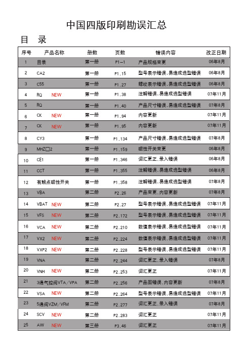
中文四版-SMC样本
20~40
CAT.C04-02A
20~40
CAT.C04-02A
40~100
CAT.C09-03A
32~125
CAT.C05-09B
32~100
CAT.C06-06A
125~300 8~25
CA3T2.C~05-2052B0
20~63 32~100
正确内容
32~100
CAT.C08-04B
12~100
07年8月 06年8月 06年8月 06年8月 06年8月 07年8月
说明:1.中国四版06年1月份正式印刷完成,06年8月份第一次增印,改动10页,07年8月份第二次增印,改动15页, 07年11月第三次增印,改动18页。
2.请注意将将更改信息通知相关客户,订货时予以确认。
执行元件
系列
气缸类型
缸径(mm) 中文样本编号 英文样本编号 日文样本编号 页号
页数 P3.55 P4.25 P4.26
错误内容 可换件型号错误 数值表示错误 型号表示错误、易造成选型错误
P4.34 P4.42
词汇更正、录入错误 型号表示不清、易造成选型错误
P4.64 P4.70
词汇更正、录入错误 追加系列
P4.102 型号表示内容错误
P4.110 型号表示内容错误
P5.09 数值表示错误
标准型气缸
图形符号
CA2系列 ( ~ )
1
1
。
弯
1系列
1
。
。 。
。
型号表示方法
mm
拉杆安装
除A54外 仅A54 BT-04 BT-06 BT-08
参见P.1.357。
正确内容
F
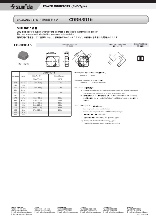
CDRH3D16中文资料
Japan Tel:(81) 03 3667-3302 Fax:(81) 03 3667-3408 E-mail: sales@
Hong Kong Tel:(852) 2880-6688 Fax:(852) 2565-9600 E-mail: sales@
Measuring Freq. (L) / インダクタンス測定周波数(L) CDRH3D16 100 kHz
Tolerance of Inductance / インダクタンス公差 CDRH3D16 1.5 µ H – 33 µ H ± 30%(N)
Rated Current / 定格電流とは *4 It is either the inductance is 35% lower than its nominal value in D.C. saturation characteristics or temperature raise becomes ∆T=30 °C (Ta=20 °C), whichever is lower.
CDRH3D16
4.0MAX.
DIMENSIONS (mm)
外形寸法図
LAND PATTERNS (mm)
推奨ランド寸法
CONSTRUCTION
磁気構造図
AX .
1.8MAX.
1.
2M
5
5.
1.
1
5.
4
2
4.
2. 4
4.0M AX.
1.
( 1.5µH - 33µH )
4
CDRH3D16
Parts No. L (H) D.C.R.( Ω ) : Max.(Typ.) 1R5 1R8 2R2 2R4 3R2 3R3 4R7 6R8 100 150 220 330 470 680 1.5 µ 1.8 µ 2.2 µ 2.4 µ 3.2 µ 3.3 µ 4.7 µ 6.8 µ 10 µ 15 µ 22 µ 33 µ 47 µ 68 µ 85m( 65m) 105m( 80m) 170m(130m) 210m(160m) 295m(225m) 430m(330m) 675m(520m) 1.10 72m( 55m) 1.20 52m( 40m) Rated Current (A) *4 1.55
东芝 16排CT 参数表

TOSHIBA Aquilion 16 CT技术参数及相应配置机器型号以及层数TOSHIBA Aquilion 16 国际论证(注册证)FDA 国内论证(注册证) SFDA 主要参数一、机架系统滑环类型低压滑环机架驱动方式磁悬浮直接驱动/直线电机直接驱动扫描架孔径 72cm 扫描架倾角±30° 固态探测器类型稀土陶瓷机架系统可遥控可由控制台遥控焦点到扫描野中心距离60cm 数据传输方式射频传输探测器排列数 40排每排探测器有效单元数896个每排探测器物理层厚0.5mm 探测器主Z轴宽度 32mm 数据采集系统通道数896个探测器保用时间一年三维激光定位系统具备,定位精度±1mm 机架冷却方式风冷心电显示方式外置心电监测倾斜螺旋扫描时机架倾±30° 斜角度二、扫描参数00最快扫描时间/3600.5s/360 每圈扫描层数 16层最薄扫描层厚 0.5mm 最薄图像重建层厚 0.5mm 最大扫描层厚 8mm 可选择的扫描层厚序列0.5mm,1mm,2mm,3mm,4mm,6mm,8mm图像重建速度(多少幅10幅/s, 512X512矩阵 /S、512X512矩阵)图像实时重建速度(多少12幅/S、512X512矩阵幅/S、512X512矩阵)扫描视野个数及尺寸 5个扫描野,18,24,32,40,50cm 图像重建矩阵512x512 图像显示矩阵512x512,1024x1024 单次螺旋连续最长扫描100s 时间单次螺旋扫描最大范围175cm 定位像方向后前,前后定位像长度175cm 螺旋扫描螺距可调范围0.625-1.5 G 螺距自由选择具备扫描模式常规/螺旋/动态/倾斜螺旋自动螺旋螺旋模式三、高压系统球管阳极热容量(提供%)7.5MHu 球管阳极冷却率 1386KHu/min 球管冷却方法油冷管电流 10-500mA 最小球管电流输出 10mA 最大球管电流输出 500mA 最大球管电压135KV 最小球管电压80KV 球管保用方法(时间、秒 20万圈次次/360度)球管小焦点0.8mmx0.9mm 球管大焦点 1.4mmx1.6mm 球管电压选择个数四档80KV 100KV 120KV 135KV 高压发生器功率 60KW 四、扫描床扫描床面宽度47cm 最大移动范围219cm 最大可扫描范围180cm 床移动误差(要求在载重±0.25mm 大于等于200Kg)床垂直升降范围30-94cm 最大垂直移床速度30mm/s 最大水平移床速度130mm/s 最小床面高度30cm 扫描床最大载重量205Kg 五、图像质量(20cm (8 Inch)CATPHAN体模检测)高密度分辨率(X,Y轴)(标准图像重建) 可视下18lp/cm@0%MTF (多少%MTF) 低密度分辨率(多少mGy), *******%@26.7mGy(标准图像重建)可视下各向同性分辨率0.35mm 水模均匀度噪声(多少mGy下扫描)<0.5% 120 kV 500 mA 标准CT值范围 -1536至+8191 拓展CT值范围 -32768至+32767 六、主控制台计算机系统内存 1.5G 硬盘 217GB 主频3.0GHzx2 原始数据硬盘容量144GB 图像存储量幅数(512×200,000幅512的不压缩图像)重建矩阵 512x512 显示矩阵 512x512/1024x1024 重建时间(每秒多少幅)10幅/s 高分辨率液晶平面显示1024x1024 器,显示矩阵(M*M)显示器逐行扫描网络接口DICOM 3.0 具备永久贮存刻录方式 CD/DVD-RW 刻录图像能否双向传输具备遥控维修诊断接口具备,选件激光相机DICOM3.0接口提供提供Dicom3.0,所有传出提供,选件及传入接口功能自动照相技术具备自动语音系统及双向语具备音传输同步并行图像处理功能具备主控制台可以独立完成MPR,SSD,MIP,CTA,三维具备MPR 容积重建等三维后处理功能并行重建功能:并行处理多种模式的图像的重建与重组,可以在一个扫描具备方案中预置和完成不同算法的重建任务七、独立工作站CPU 3.0GHzx2 3G 内存 73G 硬盘显示器(LCD)同上分辨率1280X1024 200 图像从主机到工作站的传输速度(多少幅/秒)CD/DVD-R 图像光盘存储工作站具有联网功能,与具备,选件主机之间图像双向传输工作站是否可以处理多可以种DICOM影像设备具有所有DICOM3.0 具备八、主要应用软件线束硬化伪影校正软件具备(主控台实现)后颅窝图像优化技术具备(主控台实现)各种伪影消除软件具备(主控台实现)图像减影功能具备(工作站实现)CT电影功能具备(工作站实现)管电流自动调节功能具备(主控台实现) MPR、MPVR 具备(主控台实现MPR、工作站实现MPR、MPVR)CT牙科分析功能具备,选件(工作站实现)CT介入具备,选件(主控台实现) CT骨密度分析功能价无模拟手术刀功能具备(工作站均实现)三维(3D、SSD)软件具备(工作站均实现)最大及最小密度投影具备(工作站均实现) (MIP, MinP) 三维容积测量评估功能具备(工作站均实现)CTA 具备(工作站均实现)一键式容积重建具备(工作站均实现)同步减影软件具备,选件(工作站实现)一键式自动去骨软件具备(工作站实现)容积透明重建功能具备(工作站实现)特定结构的自动提取或具备(工作站实现)者隐藏造影剂自动跟踪软件具备(主控台实现)造影剂测试计划软件不需要,已经有上面的造影剂自动跟踪软件实时三维软件具备(工作站实现)肺功能通气评价软件具备(工作站实现)容积漫游 VRT 具备(工作站实现)节段重建软件不具备CT灌注软件(有几种灌注具备(神经灌注)(全身灌注北京软件,并说明)奥德赛),选件计算机辅助肺小结节诊不具备断软件心脏扫描成像软件包不具备心电门控及附件具备心脏扫描软件包及硬件具备前瞻性ECG触发扫描具备(主控台实现)心电图编辑软件具备(工作站实现)自动期相重建技术具备(工作站实现)多种重建时相选择方法具备(工作站实现)心功能分析软件包具备(工作站均实现)冠状动脉一键式提取功不具备能不具备斑块成分定量分析功能不具备冠状动脉钙化评分软件具备(前门控主控台实现、后门有前后门控软件控工作站实现)儿童成像软件具备,选件(主控台实现)工作站与其他影像设备具备(DSA、MR、X-ray等)联网的功能九网络100Mb 网络连接多少M DICOM功能具备包括具备,(工作站实现)选件DICOM PRINT,DICOM STORE,DIOCM QUERY,DICOM RETRIVE, WORKLIST 及PPS 与现有的HIS.RIS设备的具备(工作站实现)连接原始数据能传输到现有具备工作站上进行处理。
[图]CT-16A 2P_CT-16A 2P
![[图]CT-16A 2P_CT-16A 2P](https://img.taocdn.com/s3/m/807b2cd77f1922791688e86a.png)
万联189058717858李凌富QQ:413059157[图]CT-16A/2P_CT-16A/2P适用范围施耐德家用接触器,CT-16/1P,ICT-16/1P家用交流接触器(以下简称接触器)主要适用于交流50Hz(或60Hz),额定工作电压至400V额定工作电流至63A的电路中,控制家用电器和类似用途的低感微感负载;也可用来控制家用电动机负载,此时控制功率要相应降低。
产品应用于家庭、宾馆、公寓等场所,实现自动化功能,应用于大规模生产的家用电器产品中。
符合标准:GB 17885、IEC 61095。
2 型号及含义W C T 16 NO NC39 带手动控制功能的接触器WCT 2NO2NC 220~240V 25A40 带手动控制功能的接触器WCT 2NO 220~240V 63A41 带手动控制功能的接触器WCT 2NC 220~240V 63A42 带手动控制功能的接触器WCT 3NO 220~240V 63A43 带手动控制功能的接触器WCT 4NO 220~240V 63A44 带手动控制功能的接触器WCT 2NO2NC 220~240V 63A45 触头状态指示附件辅助iACTs 2NO46 触头状态指示附件辅助iACTs 1NO+1NC47 卡夹3 正常工作条件和安装条件3.1 周围空气温度为:-5℃~+40℃,24小时内平均值不超过+35℃。
3.2 海拔高度:不超过2000m。
3.3 大气条件:安装地点的空气相对湿度在最高温度为+40℃时不超过50%;在较低的温度下允许有较高相对湿度,例如+20℃时达90%,对由于温度变化偶尔产生的凝露应采取特殊的措施。
3.4 污染等级:污染等级2。
3.5 安装类别:安装类别Ⅱ。
3.6 安装方式:采用TH35-7.5型钢安装轨安装。
3.7 防护等级:IP204 主要参数及技术性能4.1 按极数分类:接触器分为二极和四极。
4.2 接触器的额定绝缘电压、约定自由空气发热电流、使用类别及其对应的额定以额定控制电源电压Us,使其发热至稳定状态时,接触器在(85%~110%)Us范围内任何电压下能可靠地闭合。
HSV16伺服说明书

目录第一章安全警告…… …… ……… … … … … … …1 –11.1 与安全有关的符号说明… … … … … ……1-11.2 产品的警告标识… … … … … … …… …1-21.3 警告标志的内容… … … … … … … ……1-21.4 安全注意事项… … … … … … … … …1-3第二章概述… … … … … … … … … … …………2-12.1 产品简介……………………………………2-12.2 运行模式简介………………………………2-2第三章订货信息……………………………………………3-12.1 驱动器规格……………………………………3-13.2 伺服电机规格…………………………………3-43.3 隔离变压器规格………………………………3-7 第四章安装… … … … … … … …………… ……4-14.1 到货检查……………………………………4-14.2 安装环境……………………………………4-24.3 驱动器安装…………………………………4-34.4 伺服电机安装………………………………4-7 第五章接线… … … … … … … … … … … …5-15.1 标准接线……………………………………5-15.2 信号与功能…………………………………5-55.3 接口电路………………………………………5-11 第六章操作与显示………………………………………6-16.1 键盘操作…… … ……………………………6-16.2 参数的修改与保存…………… … …………6-96.3 JOG运行………………………………… ……6-106.4 内部测试运行………………… … …………6-11第七章参数设置…………………………………………7-17.1 功能菜单… ……………………………………7-17.2 运动参数模式………………………………7-27.3 控制参数模式… ………………………………7-9 第八章运行调整…………………………………………8-18.1 电源连接………………………………………8-18.2 试运行…………… ……………………………8-48.3 调整………………………………………………8-8 第九章故障诊断……………………………………………9-19.1 保护诊断功能…………………………………9-19.2 故障分析………………………………………9-3 第十章串口通讯软件………………………………… 10-110.1 如何连接………………………………………10-110.2 运行程序………………………………………10-110.3 注意事项………………………………………10-7 第十一章保养与维护……………………………………11-111.1 日常检查………………………………………11-111.2 定期检查………………………………………11-111.3 部件替换指南…………………………………11-2第一章安全警告感谢您选用HSV-16交流伺服系统。
FPGA可编程逻辑器件芯片EP3C16F256I7N中文规格书

Operating ConditionsTable 4–20 provides information on recommended input clock jitter foreach mode.Notes to Table 4–19:(1)Dedicated REFCLK pins were used to drive the input reference clocks.(2)Jitter numbers specified are valid for the stated conditions only.(3)Refer to the protocol characterization documents for detailed information.(4)HiGig configuration is available in a -3 speed grade only. For more information, refer to the Stratix II GX Transceiver Architecture Overview chapter in volume 2 of the Stratix II GX Device Handbook .(5)Stratix II GX transceivers meet CEI jitter generation specification of 0.3 UI for a V OD range of 400mV to 1000 mV . (6)The Sinusoidal Jitter Tolerance Mask is defined only for low voltage (LV) variant of CPRI.(7)The jitter numbers for SONET/SDH are compliant to the GR-253-CORE Issue 3 Specification.(8)The jitter numbers for Fibre Channel are compliant to the FC-PI-4 Specification revision 6.10.(9)The jitter numbers for XAUI are compliant to the IEEE802.3ae-2002 Specification.(10)The jitter numbers for PCI Express are compliant to the PCIe Base Specification 2.0.(11)The jitter numbers for Serial RapidIO are compliant to the RapidIO Specification 1.3.(12)The jitter numbers for GIGE are compliant to the IEEE802.3-2002 Specification.(13)The jitter numbers for HiGig are compliant to the IEEE802.3ae-2002 Specification.(14)The jitter numbers for (OIF) CEI are compliant to the OIF-CEI-02.0 Specification.(15)The jitter numbers for CPRI are compliant to the CPRI Specification V2.1.(16)The HD-SDI and 3G-SDI jitter numbers are compliant to the SMPTE292M and SMPTE424M Specifications.(17)The Fibre Channel transmitter jitter generation numbers are compliant to the specification at βT interoperability point.(18)The Fibre Channel receiver jitter tolerance numbers are compliant to the specification at βR interoperability point.Table 4–19.Stratix II GX Transceiver Block AC Specification Notes (1), (2), (3)(Part 19 of 19)Symbol/Description Conditions -3 SpeedCommercial SpeedGrade-4 Speed Commercial and Industrial Speed Grade -5 Speed Commercial Speed Grade Unit MinTyp MaxMin Typ Max Min Typ Max Table 4–20.Recommended Input Clock Jitter (Part 1 of 2)ModeReference Clock (MHz)Vectron LVPECL XO Type/Model Frequency Range (MHz)RMS Jitter (12 kHz to 20 MHz) (ps)Period Jitter (Peak to Peak) (ps)Phase Noise at 1 MHz (dB c/Hz)PCI-E100VCC6-Q/R 10 to 2700.323-149.9957(OIF) CEIPHY156.25VCC6-Q/R 10 to 2700.323-146.2169622.08VCC6-Q 270 to 800230Not available GIGE62.5VCC6-Q/R 10 to 2700.323-149.9957125VCC6-Q/R 10 to 2700.323-146.9957XAUI 156.25VCC6-Q/R 10 to 2700.323-146.2169Table4–32.LVPECL SpecificationsSymbol Parameter Conditions Minimum Typical Maximum Unit V CCIO (1)I/O supply voltage 3.135 3.3 3.465V V ID Input differential voltage3006001,000mV swing (single-ended)V ICM Input common mode voltage 1.0 2.5V V OD Output differential voltageR L = 100 Ω525970mV (single-ended)R L = 100 Ω1,6502,250mV V OCM Output common modevoltage90100110ΩR L Receiver differential inputresistorNote to Table4–32:(1)The top and bottom clock input differential buffers in I/O banks 3, 4, 7, and 8 are powered by V CCINT, not V CCIO.The PLL clock output/feedback differential buffers are powered by VCC_PLL_OUT. For differential clockoutput/feedback operation, connect VCC_PLL_OUT to 3.3 V.Table4–33.3.3-V PCI SpecificationsSymbol Parameter Conditions Minimum Typical Maximum Unit V CCIO Output supply voltage 3.0 3.3 3.6V V IH High-level input voltage0.5 V CCIO V CCIO + 0.5V V IL Low-level input voltage–0.30.3 V CCIO V V OH High-level output voltage I OUT = –500 μA0.9 V CCIO V V OL Low-level output voltage I OUT = 1,500 μA0.1 V CCIO VTable4–34.PCI-X Mode 1 SpecificationsSymbol Parameter Conditions Minimum Typical Maximum Unit V CCIO Output supply voltage 3.0 3.6V V IH High-level input voltage0.5 V CCIO V CCIO + 0.5V V IL Low-level input voltage–0.30.35 V CCIO V V IPU Input pull-up voltage0.7 V CCIO V V OH High-level output voltage I OUT = –500 μA0.9 V CCIO V V OL Low-level output voltage I OUT = 1,500 μA0.1 V CCIO VTiming Modelt M4KDATABH B port data holdtime after clock203 213 226 272 pst M4KRADDRBSU B port addresssetup time beforeclock22 23 24 29 pst M4KRADDRBH B port addresshold time afterclock203 213 226 272 pst M4KDATACO1 Clock-to-outputdelay when usingoutput registers334 524 334 549 334 584 334 701 pst M4KDATACO2 Clock-to-outputdelay withoutoutput registers1616 2453 1616 2574 1616 2737 1616 3286 pst M4KCLKH Minimum clockhigh time1250 131213951675 pst M4KCLKL Minimum clocklow time1250 131213951675 pst M4KCLR Minimum clearpulse width144 151 160 192 ps(1)The M512 block f MAX obtained using the Quartus II software does not necessarily equal to 1/TM4KRC.(2)This column refers to –3 speed grades for EP2SGX30, EP2SGX60, and EP2SGX90 devices.(3)This column refers to –3 speed grades for EP2SGX130 devices.Table4–61.M-RAM Block Internal Timing Microparameters(Part 1 of2)Note(1)Symbol Parameter-3 SpeedGrade (2)-3 SpeedGrade (3)-4 SpeedGrade-5 SpeedGrade Unit Min Max Min Max Min Max Min Maxt MEGARC Synchronous readcycle time1866 2774 1866 2911 1866 3096 1866 3716 pst MEGAWERESU Write or read enablesetup time beforeclock144 151 160 192 pst MEGAWEREH Write or read enablehold time after clock 394043 52 psTable4–60.M4K Block Internal Timing Microparameters(Part 2 of2) Note(1)Symbol Parameter -3 Speed Grade(2)-3 Speed Grade(3)-4 Speed Grade-5 Speed GradeUnit Min Max Min Max Min Max Min Max。
磁性开关SMC

磁 D-A7□H/A80H型
性 D-A73C/A80C型
开 D-A79W型
关 D-A5/A6型
D-A59W型
D-A9型
D-A9□V型
D-E7□A/E80A型
D-Z7/Z8型
D-P7型
D-B3型
执行元件页码索引 (圆型数字为Best No.。)
4P.1055 4P.1076 4P.1080 4P.1089 4P.1095 4P.1170 4P.1187 4P.1211 4P.1327 4P.1355 4P.1389 4P.1443 4P.1469 4P.1495 4P.1507 4P.1525 4P.1545 )P.15 )P.33 )P.35 )P.35 )P.165 )P.181 )P.205
ø4 ø6·ø10·ø16 ø10·ø16 ø6 ø10·ø16 ø20~ø40 ø20~ø40 ø20~ø40 ø20~ø63 ø80·ø100 ø20~ø63 ø80·ø100 ø20~ø63 ø80·ø100 ø32~ø100 ø32~ø125 ø40~ø100 ø32~ø125 ø40~ø100 ø40~ø100 ø40~ø100 ø125~ø200 ø125~ø160 ø6~ø20 ø6~ø32 ø12~ø20 ø25 ø12~ø25 ø32~ø100 ø125~ø160 ø180~ø200 ø16~ø63 ø20·ø25 ø32~ø50 ø12~ø25 ø32~ø100 ø20~ø40 ø25~ø63
点 磁 性 开 关
D-F5BA型 D-F5□W/J59W型 D-F59F型 D-F5NT型
D-G39C/K39C型
D-M9型
D-M9□V型
D-M9□W型
D-M9□WV型
D-M9□A型
SAN-16中文资料

GAMEWELL-FCI12 Clintonville Road, Northford, CT 06472-1610 USA • Tel: (203) 484-7161 • Fax: (203) 484-7118Specifications are for information only, are not intended for installation purposes, and are subject to change without notice. No responsibility is assumed by Gamewell-FCI for their use.©2007 Honeywell International Inc. All rights CS-2027 Rev. A page 1 of 2600 Series SAN, SAN-RCSerial Annunciator DriverDescriptionThe 600 Series serial annunciator driver (SAN) is used to light a lamp or LED in an annunciator. It also provides a switched positive output per point for interface with building automation systems or driving relays. Each device is capa-ble of interpreting the instructions from the main CPU, initi-ating its own programmed response, and retransmitting the instructions to the next device.The Gamewell-FCI 600 systems can accommodate up to 64 devices connected to the serial communications port. In addition to the serial annunciator drives (SAN), these devices include remote annunciator (R AN) and remote printer interface (R PI). This combination of devices com-prise the Gamewell-FCI status control network. Since each device contains its own microprocessor, each can be pro-grammed independently. A series of devices can be pro-grammed directly over the network from a single device,saving valuable installation time. Programming is accom-plished via Windows ®-based configuration software.Each SAN input point can activate up to five output points for matrix annunciation. There are two basic models avail-able, the SAN and the SAN-RC. The SAN-16 is equipped with 16 freely programmable outputs which can be used for remote control or monitoring, expandable to 128 points using PDM modules.The SAN-16-RC has all of the features of the SAN-16, plus the ability to read inputs into the system. The SAN-16-RC has provisions for four inputs for: remote acknowledge,reset, signal silence, and lamp test. In addition to the basic 16 outputs, there are eight (8) common outputs for: com-mon system alarm, common system trouble, AC power,communications, action required LED prompts for system acknowledge, reset and signal silence, and a driver for a local audible.The status control network, including SAN units, is con-nected to the main 600 Series control panel via an RS-232data communication line. The SIM-232 module is used toFeatures•Up to 64 devices supported on a single 600 Series control panel.•Windows ®-based field programming.•Dual optically isolated serial ports.•Can interface with building automation systems via standard ASCII communication.•Microprocessor based.•Expandable in 16 point increments to 128 points.Supervised.•Allows remote system control.•Mounting track included.An ISO 9000-2000 Company7120-1288:149SIGNALINGS521SAN, SAN-RCMicrosoft ® Windows ® is a registered trademark of Microsoft ® Corporation.g w f 2027p h 1.w m fGAMEWELL-FCI12 Clintonville Road, Northford, CT 06472-1610 USA • Tel: (203) 484-7161 • Fax: (203) 484-7118CS-2027 Rev. A page 2 of 2 provide an isolated RS-232 output from the main CPU of the 600 Series system panels. The IF602 and IF610 panels have built-in RS-232 ports.ApplicationsThe SAN units provide a means for remote annunciation and control of the system via a simple RS-232 connection.These driver units fit neatly into an annunciator unit and can be used to drive the LED or incandescent lights of a standard or graphic-type annunciator. When it is necessary for remote system control, the SAN-16-RC provides for up to eight inputs for system control. Any or all inputs may be used to customize any given command station’s capabili-ties.The SAN units can also be used to interface with other building systems via ASCII or where dry contacts or a switched output is required. The SAN’s outputs can be used to drive a relay to interface or control virtually any remote point or group of points.Engineer’s SpecificationsRemote annunciation and control for the main control panel shall be supplied where indicated. R emote annunciation and control shall be accomplished via the R S-232 data communications line. It shall be possible to add up to 64devices to the communication line. Each device shall be capable of driving up to 128 points. It shall be possible to mix annunciators, printers and LCD alphanumeric displays on a single line without the need for special software.Devices shall not be placement sensitive. All devices shall be individually field programmable and independent from each other. The device shall be Gamewell-FCI part numbers..SpecificationsSerial AnnunciatorDriver: Basic SAN and SAN-RC provide 16-point drives.SANInput Power:24 VAC/VDC Standby Current:0.04 A max.Alarm Current: 2.0 A max.Output Power:0.040 A max. per output.Dimensions:12” W x 4” H x 2” D(30.5 W x 10.2 H x 5.1 D cm)PDM-16 Point Drive ModuleInput Power:From SAN Module Standby Current:0.002 A Alarm Current:0.002 AOrdering InformationModelDescriptionSAN-16Serial annunciator driver module, main driver with 16-outputs.SAN-#Serial annunciator driver module, specifynumber of outputs in 16-point increments (i.e., SAN-32, SAN-48, SAN-128). Includes mounting track and interconnect cables.Contact the Gamewell-FCI Technical Support for details.SAN-16-RC Serial annunciator driver with four-remotecontrol inputs, eight (8) common outputs and 16-outputs.SAN-#-RC Serial annunciator driver with four- remotecontrol inputs, eight (8) common outputs and a specifiable number of outputs in 16-point increments (i.e., SAN-32-RC, SAN-48-RC, SAN-128-RC). Includes mounting track and interconnect cables.Contact Gamewell-FCI Technical Support for details.PDM-16Point driver module for field-expandingserial annunciator drivers, 16 outputs.SIM-232Required serial interface module, mounts in600 Series control 632, 654, and 658 to sup-ply RS-232 ouputs.Note: This model is not required for use with the IF602 and IF610 Systems.GW70703Programming cable (Programmed via aWindows ®-based SAN program). Found on the Gamewell-FCI website.Note: This program is only available to Gamewell-FCI authorized distributors.。
CDRH3D16,3D16HP,3D16LD(功率电感)
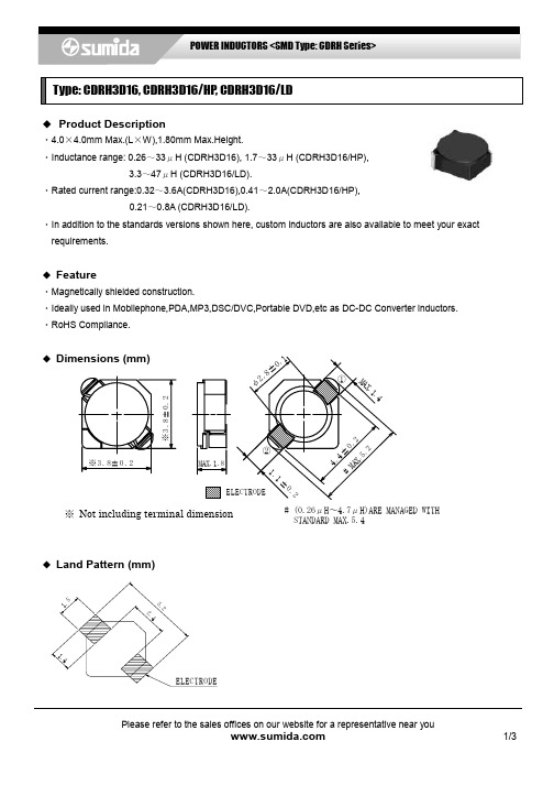
Type: CDRH3D16, CDRH3D16/HP , CDRH3D16/LD◆ Product Description・4.0×4.0mm Max.(L ×W),1.80mm Max.Height.・Inductance range: 0.26~33μH (CDRH3D16), 1.7~33μH (CDRH3D16/HP),3.3~47μH (CDRH3D16/LD).・Rated current range:0.32~3.6A(CDRH3D16),0.41~2.0A(CDRH3D16/HP),0.21~0.8A (CDRH3D16/LD).・In addition to the standards versions shown here, custom inductors are also available to meet your exact requirements.◆ Feature・Magnetically shielded construction.・Ideally used in Mobilephone,PDA,MP3,DSC/DVC,Portable DVD,etc as DC-DC Converter inductors. ・RoHS Compliance.◆※ Not including terminal dimension◆ Land Pattern (mm)#(0.26μH~4.7μH)ARE MANAGED WITHSTANDARD MAX.5.4Type: CDRH3D16, CDRH3D16/HP , CDRH3D16/LD◆ Specification(CDRH3D16)※1 Rated current: The DC current at which the inductance decreases to 65% of it's nominal valueor when △t=30℃, whichever is lower(Ta=20℃).◆ Specification(CDRH3D16/HP)Saturation Current(A )※1 Part Name※StampInductance (μH) [Within ] 100kHz/1VD.C.R. (m Ω) Max.(Typ.) (at 20℃)(at 20℃)(at105℃)Temperature Rise current (A) ※2CDRH3D16/HPNP-1R7N □ A 1.7±30% 51(41) 2.0 1.5 2.40 CDRH3D16/HPNP-2R2N □ C 2.2±30% 59(47) 1.75 1.3 2.30 CDRH3D16/HPNP-3R3N □ E 3.3±30% 85(68) 1.4 1.1 1.80 CDRH3D16/HPNP-4R7N □ G 4.7±30% 116(93) 1.2 0.9 1.50 CDRH3D16/HPNP-6R8N □ J 6.8±30% 180(145) 1.0 0.721.10 CDRH3D16/HPNP-1ØØM □L 10±20% 230(185) 0.84 0.621.00 CDRH3D16/HPNP-15ØM □ N 15±20% 410(328) 0.65 0.52 0.75 CDRH3D16/HPNP-22ØM □ P 22±20% 610(488) 0.55 0.43 0.52 CDRH3D16/HPNP-33ØM □ Q 33±20% 870(695) 0.46 0.350.41Part Name※ StampInductance (μH) [Within ] 100kHz/1VD.C.R.(m Ω) Max.(Typ.) (at 20℃)Rated current (mA) ※1CDRH3D16NP-R26N □ R 0.26±35% 27.5(21) 3600 CDRH3D16NP-R47N □ S 0.47±35% 35( 27) 2750 CDRH3D16NP-ØR7N □ T 0.70±35% 43( 33) 2250 CDRH3D16NP-1R1N □ U 1.10±35% 50( 38) 1900 CDRH3D16NP-1R5N □ A 1.50±30% 52( 40) 1550 CDRH3D16NP-2R2N □ C 2.20±30% 72( 55) 1200 CDRH3D16NP-3R3N □ E 3.30±30% 85( 65) 1100 CDRH3D16NP-4R7N □ G 4.70±30% 105( 80) 900 CDRH3D16NP-6R8N □ I 6.80±30% 170(130) 730 CDRH3D16NP-1ØØN □ K 10.0±30% 210(160) 550 CDRH3D16NP-15ØN □ M 15.0±30% 295(225) 450 CDRH3D16NP-22ØN □ O 22.0±30% 430(330) 400 CDRH3D16NP-33ØN □Q 33.0±30% 675(520) 320Type: CDRH3D16, CDRH3D16/HP , CDRH3D16/LD◆ Specification (CDRH3D16/LD)Saturation Current(A )※1 Part Name※StampInductance (μH) [Within ]100kHz/1VD.C.R.(m Ω)Max.(Typ.) (at 20℃)at 20℃at 100℃Temperature Rise current (A) ※2CDRH3D16/LDNP-3R3N □A 3.3±30%66(53) 0.80 0.52 2.00 CDRH3D16/LDNP-3R9N □B 3.9±30%81(65) 0.75 0.44 1.75 CDRH3D16/LDNP-4R7N □C 4.7±30%91(73) 0.68 0.43 1.72 CDRH3D16/LDNP-5R6N □D 5.6±30%102(82) 0.62 0.38 1.64 CDRH3D16/LDNP-6R8N □E 6.8±30%130(104) 0.58 0.341.30CDRH3D16/LDNP-8R2N □F 8.2±30%140(112) 0.51 0.32 1.28CDRH3D16/LDNP-1ØØN □ G 10±30% 190(152) 0.46 0.27 1.07 CDRH3D16/LDNP-12ØN □H 12±30% 205(164) 0.42 0.26 0.98 CDRH3D16/LDNP-15ØN □J 15±30% 272(218) 0.38 0.23 0.87 CDRH3D16/LDNP-18ØN □K 18±30% 327(262) 0.34 0.21 0.76 CDRH3D16/LDNP-22ØN □L 22±30% 356(285) 0.31 0.18 0.66 CDRH3D16/LDNP-27ØN □M 27±30% 470(377) 0.28 0.17 0.60 CDRH3D16/LDNP-33ØN □N 33±30% 560(446) 0.26 0.16 0.55 CDRH3D16/LDNP-39ØN □P 39±30% 700(558) 0.24 0.15 0.47 CDRH3D16/LDNP-47ØN □Q 47±30% 775(630) 0.210.130.45※ Description of Part NameCDRH3D16/LDNP-3R3N □※1.Saturation Current: The DC current at which the inductance decreases to 65% of it's nominal value ※2 Temperature rise current:The DC current at which the temperature rise is △t =40℃.(Ta =20℃)B BoxC Carrier Tape。
D3F中文资料

Previous Page | Return to Index | Next PageQ-G® CORD PLUG CONNECTORS AND RECEPTACLES1. T(*)F and T(*)FM Cord Plug With On-Off Switch2. D(*)M, D(*)F and D(*)FD Receptaclesclick here to download a schematic drawing(you will need to have Adobe Acrobat installed on your system to do this)T(*)F and T(*)FM Cord Plug With On-Off SwitchT(*)F Straight female cord plug with DPDT (2-C) lockingon-off switch; standard latchlock.T(*)FM Straight female cord plug with SPDT (1-C)momentary on-off switch; standard latchlock.Slide switches rated 500 mA, 125V (AC or DC). Mountingscrews are supplied.Part Number *Part Number Insert ContactsT3F¤T3FL3¤T3FM¤T3FLM3¤T4F¤T4FL4¤T4FM¤T4FLM4¤T5F¤T5FL5¤T5FM¤T5FLM5¤T6F¤T6FL6¤T6FM¤T6FLM6¤T7F-7¤T7FM-7* Number of insert contact or pins must be specified to complete Part Number.¤Available on special order only; contact Switchcraft for price and delivery.D(*)M, D(*)F and D(*)FD ReceptaclesStudio quality black and gold Q-G ® receptacle with black housing and gold contacts isdesigned for low/stable contact resistance and withstands corrosion where highest quality is required for recording and broadcast studio equipment, consoles, and other applications.D(*)M SERIES - Male receptacle for panel or chassis mounting. Special rectangular flange permits close spacing on crowded panels, has two .136 inch (3.45mm) diameter countersunk holes for #5-40 flat head mounting screws (not supplied). Mounts from front of panel or chassis in .766 inch (19.45) diameter hole. Satin nickel finish (Series D*M) or black finish (Series D*MB, or D*MBAU).D(*)F SERIES - Female receptacle for panel or chassis mounting. Flange has two .136-inch (3.45 mm) diameter countersunk holes for #5-40 flat head mounting screws (not supplied). Mounts from front of panel or chassis in .953-inch (24.21 mm) diameter hole. Series D(*)F has standard latchlock; Series D(*)FD has FAS-DISCONNECT detent. Satin nickel finish (Series D*F and D*FD) and "Black-Velvet" finish (Series D*FBAU).Nickel FinishBlack FinishDetent QGP Series1Pins Silver GoldD3M D3MB D3MBAU-QGP3633 D4M D4MB D4MBAU--4 D5M D5MB D5MBAU--5 D6M D6MB D6MBAU--6 D7M D7MB D7MBAU--7 D3F D3FB D3FBAU D3FD QGP3623 D4F D4FB D4FBAU¤D3FDB-4 D5F D5FB D5FBAU--5 D6F D6FB D6FBAU¤D6FDB-6 D7F D7FB D7FBAU--7* Number of insert contact or pins must be specified to complete Part Number.¤Available on special order only; contact Switchcraft for price and delivery.1 Non-reflective gray finish, gold-plated pins.Previous Page | Return to Index | Next PageTo search a category please click on the corresponding icon:| Connectors | Jacks and Plugs || Patch Panels, Patch Kits & Jackfields | Cable Assemblies and Patch Cords | Switches | All products shown are covered by Switchcraft's limited lifetime warranty.| Switchcraft home |About Us | Products | What's New | Search | Contact Us。
德国红外热像仪PCE-TC3D 说明书

成。
PCE-TC3D 标准组件:
A版 1 x 红外热像仪 , PCE-TC 3D (A 版) ,1 x 锂电池 1 x 充电器, 1 x 安全手带,1 x 便携手提包,1 x Micro-SD-存储卡 1 x 专业软件(CD),1 x USB 数据线,1 x 产品使用手册
2.2. 给 PCE-TC3D 充电 • PCE-TC3D 的电池充电可以通过将 4-6V 电源适配器插入侧面的迷你 USB 插口 来充电 (见图 2)。 • 热像仪打开后,电池电量显示在屏幕上(见图 3)。 • 绿色 LED 指示灯显示正在充电,红色表示充电完毕(见图 2)。电池充满电后可 持续工作约 5 小时 。 连接口:
•
不要在有爆炸物的环境中使用。
•
请只使用随设备一起提供的索套,以降低损坏热像仪的风险和造成
人员伤害的风险。
•
请只使用 PCE 提供的备件和附件,其它备件和附件可能损坏热像仪。
•
热像仪成像部分没有用户可自行维修的部件,打开热像仪镜头部分
的封装会导致质保期失效。对该热像仪的所有维修, 只能由授权的 PCE 维修中心完
2.3
更换电池 ............................................................... ....... ....................................6
3.. PCE 热像仪 TC5 基本特征............................................... ....................................................6
4.. 使用快捷键..............................................................................................................................9
Toshiba_16层CT参数表

刻录图像能否双向传输
具备
遥控维修诊断接口
具备,选件
激光相机 DICOM3.0 接口
提供
提供 Dicom3.0,所有传出及传 入接口功能
提供,选件
自动照相技术
具备
自动语音系统及双向语音传 输
具备
同步并行图像处理功能
具备
主控制台可以独立完成
MPR,SSD,MIP,CTA,三维容 具备 MPR 积重建等三维后处理功能
有偿升级 24 小时 具备 开放维修密码 800-810-1313 提供
外购
开机率在多少%以上
保证 95%
提供详细操作、技术维护及 调试参数资料
提供
自验收报告买卖双方确认开
始质保期
备注:
如果需要修改以及添加在各大技术参数栏目中请用红字表示。
如果是第三方的产品必须说明,并且注明第三方的产品、厂家以及型号等等用红字表示。
儿童成像软件 工作站与其他影像设备 (DSA、MR、X-ray 等)联网 的功能 网络 网络连接多少 M DICOM 功 能 具 备 包 括 DICOM PRINT,DICOM STORE,DIOCM QUERY , DICOM RETRIVE , WORKLIST 及 PPS 与现有的 HIS.RIS 设备的连 接 原始数据能传输到现有工作 站上进行处理。 环境以及场地要求等 室内温度 湿度 电源电压 其它 软件升级方法 维修响应时间 远程维修论断系统 维修密码提供是否需要价格 提供免费保修电话 提供现场培训 提供球管型号和更换价格 CT 专用高压注射器
TOSHIBA Aquilion 16 FDA SFDA
低压滑环 磁悬浮直接驱动/直线电机直接驱动 72cm ±30° 稀土陶瓷 可由控制台遥控 60cm 射频传输 40 排 896 个 0.5mm 32mm 896 个 一年 具备,定位精度±1mm 风冷 外置心电监测
