CTDS5022PF-683中文资料
深圳富满电子集团TC6832ES非隔离降压型LED恒流控制器说明书

TC6832ES.(文件编号:S&CIC1440)非隔离降压型LED恒流控制器概述TC6832ES.是一款高精度降压型LED恒流驱动芯片。
芯片工作在电感电流临界连续模式。
TC6832ES.芯片内部集成500V功率开关,采用专利的驱动和电流检测方式,芯片的工作电流极低,无需辅助绕组检测和供电,只需要很少的外围元件,即可实现优异的恒流特性,极大的节约了系统成本和体积。
TC6832ES.芯片内带有高精度的电流采样电路,同时采用了专利的恒流控制技术,实现高精度的LED恒流输出和优异的线电压调整率。
芯片工作在电感电流临界模式,输出电流不随电感量和LED工作电压的变化而变化,实现优异的负载调整率。
TC6832ES.具有多重保护功能,包括LED开路/短路保护,欠压保护,芯片温度过热调节等。
特点电感电流临界连续模式内部集成500V功率管无需辅助绕组检测和供电芯片超低工作电流宽输入电压±5%LED输出电流精度LED开路保护LED短路保护芯片供电欠压保护过热调节功能封装形式:SOP-8应用LED蜡烛灯、LED球泡灯其它LED照明TC6832ES.(文件编号:典型应用电路2D1-D4TC6832ES.(文件编号:S&CIC1440)非隔离降压型LED恒流控制器极限参数并不完全保证满足个别性能指标。
电气参数定义了器件在工作范围内并且在保证特定性能指标的测试条件下的直流和交流电参数规范。
对于未给定上下限值的参数,该规范不予保证其精度,但其典型值合理反映了器件性能。
注2:温度升高最大功耗一定会减小,这也是由T JMAX,θJA,和环境温度T A所决定的。
最大允许功耗为P DMAX=(T JMAX-T A)/θJA或是极限范围给出的数字中比较低的那个值。
注3:人体模型,100pF电容通过1.5KΩ电阻放电。
推荐工作范围TC6832ES.(文件编号:S&CIC1440)非隔离降压型LED恒流控制器电气参数(无特别说明情况下,V CC=15V,T A=25℃)注5:规格书的最小、最大规范范围由测试保证,典型值由设计、测试或统计分析保证。
SD6832PDF规格说明书
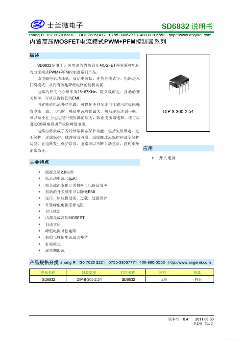
为减小在上电过程中变压器的应力,防止变压器饱和,上电时,峰值电流补偿最大,然后逐渐达到平 衡。达到平衡的时间随负载而定。
测试条件 VGS=0V,ID=50μA VDS=650V,VGS=0V VDS=480V,VGS=0V Tamb=125°C VGS=10V,ID=0.5A VGS=0V,VDS=25V,f=1MHz VGS=0V,VDS=25V,f=1MHz VGS=0V,VDS=25V,f=1MHz VDD=0.5BVDSS ,ID=25mA VDD=0.5BVDSS ,ID=25mA VDD=0.5BVDSS ,ID=25mA VDD=0.5BVDSS ,ID=25mA
SD6832 说明书
zhang R 137 2378 6618 QQ272261417 0755-33067773 400-880-5552
内置高压MOSFET电流模式PWM+PFM控制器系列
描述
SD6832是用于开关电源的内置高压MOSFET外置采样电阻
2. 频率抖动和降频模式
为了降低 EMI,本电路使得振荡频率不断的变化,减小在某一个单一频率的对外辐射。振荡频率在一个 很小的范围内变动,从而简化 EMI 设计,更容易满足要求。中心频率 67KHz 时变化的规律是:4ms 时间之 内±2.5KHz 范围变化,共有 63 个频率点。
为提高效率,本电路采用降频模式。采用方式有二: 一、 通过检测 FB 管脚输出下拉电流 IFB 来降低频率 f。当 IFB 在典型电流 I1 以上时,频率 f 从典型值 67KHz
6832芯片参数
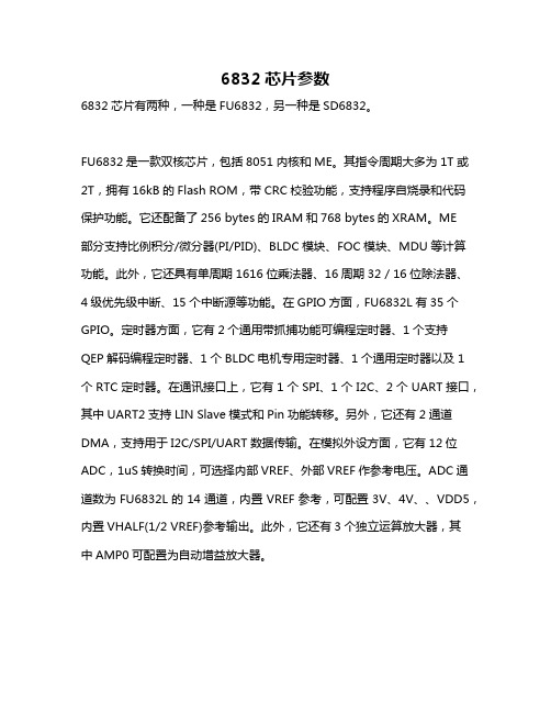
6832芯片参数6832芯片有两种,一种是FU6832,另一种是SD6832。
FU6832是一款双核芯片,包括8051内核和ME。
其指令周期大多为1T或2T,拥有16kB的Flash ROM,带CRC校验功能,支持程序自烧录和代码保护功能。
它还配备了256 bytes的IRAM和768 bytes的XRAM。
ME部分支持比例积分/微分器(PI/PID)、BLDC模块、FOC模块、MDU等计算功能。
此外,它还具有单周期1616位乘法器、16周期32 / 16位除法器、4级优先级中断、15个中断源等功能。
在GPIO方面,FU6832L有35个GPIO。
定时器方面,它有2个通用带抓捕功能可编程定时器、1个支持QEP解码编程定时器、1个BLDC电机专用定时器、1个通用定时器以及1个RTC定时器。
在通讯接口上,它有1个SPI、1个I2C、2个UART接口,其中UART2支持LIN Slave模式和Pin功能转移。
另外,它还有2通道DMA,支持用于I2C/SPI/UART数据传输。
在模拟外设方面,它有12位ADC,1uS转换时间,可选择内部VREF、外部VREF作参考电压。
ADC通道数为FU6832L的14通道,内置VREF参考,可配置3V、4V、、VDD5,内置VHALF(1/2 VREF)参考输出。
此外,它还有3个独立运算放大器,其中AMP0可配置为自动增益放大器。
SD6832是一款用于开关电源的内置高压MOSFET外置采样电阻的电流模式PWM+PFM控制器IC芯片。
其工作频率为25kHz\~67kHz,采用8脚双列直插式(8DIP)封装工艺。
请注意,不同型号的6832芯片可能具有不同的参数和特性。
如需了解更多信息,建议查阅芯片规格书或咨询芯片厂商。
电信保护产品目录说明书

Contents70 Type indicating fuses —125 AC300 DC 1/10-101015087 holders for 70 Type fuses 130012Circuit protection for telecom applicationsTPC fuses and TPCDS pullout disconnects Telpower TPC compact current-limiting fuses mount in theTPCDS compact fused pulloutdisconnect that’s available intwo disconnect profiles anda variety of terminal styles.Recommended 0.75" center-to-center product spacing.Ratings•Volts 80 Vdc•Amps 3-125 A•IR 100 kAAgency information•UL Recognized (investigated to UL 1801) as a disconnect switch for the interruption of load current by means of withdrawing the fuse pullout•Recognized to US and Canadian requirements under the component recognition program of Underwriters Laboratories Inc. Files E219046 and E56412•CETypical applications•Telecommunications DC power circuit protection •Replacement of DC telecom circuit breakers•Applications where venting of arc or molten metals and gases during opening would pose a problem to surrounding devicesFeatures•Highest interrupting rating (100 kA) available and complete system coordination for DC circuit protection for compact footprint providing a superior protection solution for replacement of existing DC telecom circuit breakers•AmpColor ID™ system makes fuse replacement easy•Local and remote open fuse indication. Local alarm indication provided by LED on TPC fuse•Remote alarm terminal available in three positions common to DC circuit protection devicesTPC fusesTPC-4TPC-10TPC-30TPC-90TPC-5TPC-12TPC-40TPC-100TPC-6TPC-15TPC-50TPC-125TPC-7TPC-20TPC-60Data sheet no. 5023TPCDS catalog number systemTPCDS-BBE-2TPCDS-BSE-3TPCDS-SSM-1TPCDS-D-SEC2* TPCDS-BBE-3TPCDS-BSM-1TPCDS-SSM-2TPCDS-D-SMC1* TPCDS-BBM-1TPCDS-BSM-2TPCDS-SSM-3TPCDS-D-SMC2* TPCDS-BBM-2TPCDS-BSM-3TPCDS-D-BC1*TPCDS-BBM-3TPCDS-SSE-1TPCDS-D-BC2*TPCDS-BSE-1TPCDS-SSE-2TPCDS-D-CC1** Not investigated to Canadian requirements.Dimensions•See data sheet no. 5023T e l e c o m p r o t e c t i o n p r o d u c t sTPM fuse and TPMDS pullout disconnectTelpower TPM miniaturecurrent-limiting fusses mount in the miniature TPMDS pullout disconnect. The TPM fusesfeature local open fuse indication and TPMDS is easily integrated into remote indication systems.Ratings•Volts 80 Vdc •Amps 3-30 A•IR 20 kAAgency information•UL Recognized (investigated to UL 1801) as a disconnect switch for the interruption of load current by means of withdrawing the fuse pullout•Recognized to US and Canadian requirements under thecomponent recognition program of Underwriters Laboratories Inc. Files E219046 and E56412•CETypical applications•Telecommunications DC power circuit protection•Applications with restricted space, or mounting in 1 U (1.75"/44.5mm) panelsFeatures•Smallest and most versatile fused disconnect switch available allowing for assembly into 1 U (1.75"/44.5mm) panel. Easy to connect:•Load: 1/4" quick-connect or bolted connection with 10-32 (M5) captive nut•Line: 1/4" quick-connect or screw connection with clearance hole for #10 (M5) bolt•AmpColor ID™ System makes fuse replacement easy•Switch design provides for easy panel mounting by single captive 4-40 (M3) nut and panel notch integral to switch footprint•Complete system coordination capability with local and remote open fuse indication. Local alarm indication provided by LED on TPM fuse (maximum alarm circuit current: 20 mA)TPM fusesTPM-4TPM-7TPM-12TPM-25TPM-5TPM-8TPM-15TPM-30TPMDS pullout disconnects (accept all TPM fuse ampratings)TPMDS-MPullout fused disconnect, metric hardwareDimensions — see data sheet no. 5022Data sheet no. 5022TPMDS alarm schematicNotes:1. The resistance (R) must be provided by the end-user to limit the open fuse indication output current to a maximum of 20mA. The “R” value should be calculated using the system voltage value. If remote indication functionality is not required, the END-USER CIRCUITRY must still be supplied to provide aresistance path to the return for the local indication to properly function.2 The fuse is polarized to maintain proper orientation with the switch housing. The line and load terminals are identified on the switch housing.TP15900-4 fused pullout disconnect for TPA fuses 4-pole fused pullout disconnectfor use with Telpower TPA andTPA-B fuses. Pullout disconnectsfeature remote open fuseindication capability.Ratings•Volts•145 Vdc@40 A per pole•80 Vdc@50 A per poleAgency information•UL Recognized File E97649 as a disconnect switch for interruption of load current by means of withdrawing the fuse carrier•UL Recognized as a component for telecommunication power distribution equipment (UL category QPQY2)•UL Recognized fuses for branch circuit protection•CSA Component Acceptance for the system•CETypical applications•Telecommunications DC power circuit protectionFeatures•Easy installation, connects directly to busbar, reduces external wiring per pole. Rear accessibility for line and load terminations•LED alarm signaling (LED current 30 mA max)•Local and remote open-fuse indication along with fuse orientation rejection feature and fuse presence indication•Alarm test probe point allows on-site alarm circuit checkingTP15900-414-pole common disconnect w/ split alarm, split lineAvailable fusesTPA-B20, 25, 306520 kA Accessories•Spare fuse holders: catalog numbers 5TPH and TPSFH-ASDimensions — mm (in)TP15914 fused pullout disconnectModular 4-pole fused pulloutdisconnect for us with TPA fuses.4-poles per module can be gangedup to four modules for a total of16 poles. The TP15914 featuresopen fuse indication and fusepresence indication along with fuseorientation rejection.Ratings•Volts 145 Vdc•Amps 50 A max per poleAgency information•UL Recognized, Guide JFHR2, File E56412•UL Recognized as a disconnect switch for interruption of load current by means of withdrawing the fuse carrier•UL Recognized as a component for telecommunication power distribution equipment (UL category QPQYZ)•UL Recognized fuses for branch circuit protection•CSA Certified, Class 1422-30, File 53787•CSA Component Acceptance for the systemTypical applications•Telecommunications DC power circuit protectionFeatures•Easy installation with totally enclosed module that connects directly to busbar to reduce external per-pole wiring.•Standard front access load and line double lug connection for 8 AWG wire•LED alarm signaling (LED current 30 mA max)•Remote alarm with alarm test probe point to allow on-site alarmcircuit checkingTP15914-1Metric hardware Accessories•Spare fuse holders: catalog numbers 5TPH and TPSFH-ASDimensions — mm (in)Data sheet no. 5001Data sheet no. 5011TPA and TPA-B indicating fusesIndicating DC power distribution fuse for use inTP15900-4 and TP15914 fused pullout disconnects.Ratings•Volts•170 Vdc (TPA)•65 Vdc (TPA-B)•Amps•3-50 A (TPA)•20-30 A (TPA-B)•IR•100 kA (TPA)•20 kA (TPA-B)Agency information•UL Recognized, Guide JFHR2, File E56412•CSA Certified, Class 1422-30, File 53787•CE, RoHS compliantTypical applications•Telecommunications DC power circuit protectionFeatures•Indication pin provides for local and remote indication whenused with Bussmann series TP15900-4 and TP15914 disconnectswitches•Patented “orange ring” fuse orientation features assures correctfuse position•The UL Recognized ratings and current-limiting capabilitymake this fuse ideal for cable protection on existing DC powerdistribution systems•A unique blue label is used on all Telpower fuses to designate theirDC capabilityAccessories•Spare fuse holders: 5 position holder; 5TPH; 6 position holder;TPSFH-ASDimensions — in (mm)Data sheet no. 50122011/65/EU15800 fused pullout disconnect for the TPS fuseFused pullout disconnect switchfor use only with the TPS mainfuses (1 to 70 amp) and GMT-Aindicating fuse (see page 14-11).It is recommend to also use theGMT-X cover for the GMT-Afuse.Ratings•Volts 60 Vdc•Amps 3-70 A•SCCR 100 kAAgency information•UL Recognized, Guide QPQY2, File E97649•CETypical applications•Telecommunications DC power circuit protectionFeatures•Alarm output with wire wrap terminal or connection to 0.063”thick common alarm busAccessories•Spare fuse holders: catalog numbers TPSFH-AS (TPS fuses) andTPSFH-T (GMT fuses)Dimensions — in (mm)Data sheet no. 5002TP158HC fused pullout disconnectHigh amp panel mount, rear access fused pullout disconnect for use only with TelpowerTPL-B main fuses (70-250 A) and GMT-A indicating fuse (see page 14-11). It is recommend to also use the GMT-X cover for the GMT-A fuse.Ratings•Volts 80 Vdc •Amps 70-250 A•SCCR 100 kAAgency information•UL Recognized (investigated to UL 1801) as a disconnect switch for the interruption of load current by means of withdrawing the fuse pullout, Guide QPQY2, File E97649Typical applications•Telecommunications DC power circuit protectionFeatures•Similar profile, mounting method, and backplane configuration as 15800. The TP158HC can be installed into existing 15800 panels using the space of two 15800 pullout disconnects•Innovative new fuse pullout design eliminates need for tools to replace the Telpower type TPL-B fuse•Alarm output with wire wrap terminal or connection to 0.063 inch (1.6mm) thick common alarm bus•Hardware included: Load: washer, split lockwasher, and 5/16 - 18 nut (metric M8 x 1.25)TP158HC-MMetricAccessories•Spare fuse holders: TPSFH-LB (TPL-B fuses) and TPSFH-T (GMT fuses)Dimensions•See data sheet no. 5021Application notesThe line connection uses a 1/4-20 bolt (metric M6 x 1) that threads into the line terminal. The line terminal is designed with a float of ±0.02" (±0.50mm) to allow for variation in the distance between the TP158HC mounting flange and the line busbar (see dimensions). Equipment should be designed to eliminate any relative movement between the TP158HC mounting flange and the line busbar.The alarm circuit is not intended for pre-charging capacitive circuits. Maximum alarm circuit current 1 A.TPS main power fuseNon-indicating DC power distribution ferrule fuses specifically designed to meet the unique needs of DC power distribution systems. For use with Bussmann series 15800 fused pullout disconnect. Vertical and horizontal PCB tab versions available for circuit board applications.Ratings•Volts 170 Vdc •Amps 1-80 A•IR 100 kAAgency information•UL Recognized, Guide JFHR2, File E56412, RoHS compliant, CETypical applications•Telecommunications DC power circuit protection•Applications requiring printed circuit board mountingFeatures•The UL Recognized ratings and current-limiting capabilitymake this fuse ideal for cable protection on existing DC power distribution systems•A unique blue label is used on all Telpower fuses to designate their DC capability•PCB tab versions eliminate the need for fuseclips when mountingthe fuse on a circuit board* LB = Bolt tagAccessories•Spare fuse holder TPSFH-AS, see page 15-4Dimensions — in (mm)Data sheet no. 5009Data sheet no. 50212011/65/EUT e l e c o m p r o t e c t i o n p r o d u c t s15100 fused pullout disconnectFused pullout disconnect system for use with TPL Telpower fuses.Ratings•Volts 60 Vdc •Amps 70-800 A•SCCR 100 kAAgency information•UL Recognized, Guide QPQY2, File E97649•CETypical applications•Telecommunications DC power circuit protectionFeatures•Single-pole fusible disconnect switch for primary DC power distribution•Robust housing and terminal construction for demanding applications •Panel mounting•Easily connected to line or load bus15100-601300-800Dimensions — in (mm)Data sheet no. 5003TPHCS high current fused pullout disconnectHigh current fused pullout disconnect for use with TPL-B, TPL-C and TPH Telpower fuses. Available as acomplete pullout disconnect or just the pullout. Base may be purchased separately.Ratings•Volts 80 Vdc •Amps 70-800 A•SCCR 100 kAAgency information•UL Recognized (investigated to UL 1801) as a disconnect switch for the interruption of load current by means of withdrawing the fuse carrier•UL Recognized to meet the requirements for Canadian StandardsTypical applications•Telecommunications DC power circuit protectionFeatures•Innovative design eliminates needing tools to replace the TPL-B, TPL-C or TPH fuses•Easy to install with captive fasteners for direct busbar mounting (bolts not included). Standard 1/4” quick-connect for easy remote alarm connection•Optional electronic alarm eliminates needing parallel indicating fuses while providing local and remote open-fuse indication(maximum remote alarm current: 20 mA); Bipolar alarm: designed for both central office and Radio applications, Local LED open fuse indication for easy viewing.•Carrier window allows easy viewing of installed fuse amp rating•Compact design is ideal for today’s high power, high-densitycabinetsTPHCS250-E English TPL-B 70-250TPHCS250-MLMetric, LED TPL-B 70-250TPHCS250-EL English, LED TPL-B 70-250TPHCS250-MAV Metric, alarm TPL-B 70-250TPHCS250-EAVEnglish, alarm TPL-B 70-250TPHCS800-M Metric TPL-C or TPH 300-800TPHCS800-E English TPL-C or TPH 300-800TPHCS800-ML Metric, LED TPL-C or TPH 300-800TPHCS800-EL English, LED TPL-C or TPH 300-800TPHCS800-MAVMetric, alarm TPL-C or TPH 300-800TPHCS800-EAVEnglish, alarmTPL-C or TPH300-800TPHCS800-MAV shownData sheet no. 5020TPL high amp DC fusesHigh amp DC power distribution fuses for use with Telpower 15100, 15200, TP158HC and TPHCS fused pullout disconnects. TPL-TA adapter kit isnecessary when replacing a UBO fuse.Ratings•Volts 170 Vdc •Amps 70-800 A•IR 100 kAAgency information•UL Recognized Guide JFHR2, File E56412 Bellcore•CETypical applications•Telecommunications power circuit protectionFeatures•Current-limiting design for DC power distribution systems •UL Recognized branch circuit protection •Complete system coordination capability•Energy savings with low watts loss, low operating temperatures, and minimum I 2t levelsAccessories•Spare fuse holders: TPSFH-LB (for TPL-B fuses) TPSFH-LC (for TPL-C fuses)Dimensions — in (mm)Data sheet no. 5005TPL-CN, TPL-CR, TPL-CV and TPL-CZTPHCS800-P Pullout only (800 A)TPL-C or TPH300-800TPHCS-B-M Base only, metric —800 max TPHCS-B-E Base only, English —800 max TPHCS-B-ML Base only, metric, LED —800 max TPHCS-B-EL Base only, English, LED —800 max TPHCS-B-MAV Base only, metric, alarm —800 max TPHCS-B-EAVBase only, English, alarm—800 maxNotes1. TPHCS250 and TPHCS800 pullouts and bases are the same with exception to the fuse type the pullout will hold (TPL-B, TPL-C or TPH).2. Plastic rated UL 94V0, 140ºC RTI.Dimensions — mm (in)Data sheet no. 5020T e l e c o m p r o t e c t i o n p r o d u c t sTPN high amp current limiting DC fusesThe TPN fuse is a current-limiting DC power distribution fuse that’s dimensionally similar to UL Class R branch circuit fuses making them easy to install using standard RM60_ modular Class R fuse blocks.Ratings•Volts 170 Vdc •Amps 1-600 A•IR 100 kAAgency information•UL Recognized, Guide JFHR2, File E56412Typical applications•Telecommunications power circuit protectionFeatures•Current-limiting design for DC power distribution systems •Recognized branch circuit protection •Complete system coordination capability•Energy savings with low watts loss, low operating temperatures, and minimum I 2t levelsTPN-3TPN-35TPN-100TPN-300TPN-5TPN-40TPN-110TPN-350TPN-6TPN-45TPN-125TPN-400TPN-10TPN-50TPN-150TPN-450TPN-15TPN-60TPN-175TPN-500TPN-20TPN-70TPN-200TPN-600TPN-25TPN-80TPN-225Accessories•Spare fuse holders:TPSFH-N30 (for TPN 1-30) TPSFH-N60 (for TPN 35-60)Recommended modular* Class R fuse blocksRM25060-1CR 60RM25100-1CR 100RM25200-1CR 200RM25400-1CR 400RM25600-1CR600* Blocks can be snapped together to create the number of required poles. Optional indicating and non-indicating finger-safe covers available for all blocks.Data sheet no. 50060.81(21)35 A to 60 A0.5670A to 100A110A to 200A225A to 400A1.56(38)1.06(27)Dimensions — in (mm)70 Type pin indicating fusesPin indicating fuse for use in the 15087 panel-mount fuse holder. Ratings•Volts•125 Vac•300 Vdc•Amps 1/10-10 A•IR 1 kA @ 300 VdcAgency information•UL Recognized, Guide JDYX2, File E19180 Bellcore•CE70R-15/100A*Red/White101384550KS23751-L11 70E-18/100A*Y ellow100203363KS23751-L5 70X-2/10A Black——70F-1/4A*Violet100203371KS23751-L6 70K-1/4A*Violet/White100203405KS23751-L9 70G-1/2A*Red100203389KS23751-L7 70H-3/4A*Brown100203397KS23751-L8 70I-1A Pink——70A-1-1/3A*†White100203322KS23751-L1 70B-2A*Orange100203330KS23751-L2 70C-3A*Blue100203348KS23751-L3 70J-3-1/2A Black/White——70D-5A*Grn/Black100203355KS23751-L4 70L-6A Grn/White——70M-8A Brown/White——70N-10A Violet/Y ellow——72A Plastic Case (dummy)100203421—72B Blister Pack (dummy)103757977—* Product designed to comply with Bellcore Technical Reference TR-TSY-000799 Issue 1, December 1988.† Not UL Recognized.Data sheet no. 500715087 fuse holderPanel mount fuse holder for use with 70 Type fuses.Ratings•Volts 300 Vdc•Amps 12 AAgency information•UL Recognized, Guide IZLT2, File E14853•CEFlammability rating•UL 94V0Catalog number 15087Typical applications•Telecommunications DC power circuit protectionFeatures•Panel mount fuse holder for 70 type fuses supplied with two screws•Remote alarm capabilityOptional color-code eyeletsColor-coded eyelets are used with the fuse holder to indicate itsfuse amp rating.1A1706-0118/100Y ellow1A1706-151/10Gray/White 1A1706-022/10Black1A1706-031/4Violet1A1706-041/4Violet/White 1A1706-051/2Red1A1706-063/4Brown1A1706-071Pink1A1706-081-1/3White1A1706-092Orange1A1706-103Blue1A1706-163-1/2Black/White 1A1706-115Green/Black 1A1706-126Green/White 1A1706-138Brown/White 1A1706-1410Violet/YellowData sheet no. 5007Telecom protection products — 14HLS, HLT, PCT holders for GMT indicating fusesConfigurable fuse holders for use with GMT indicating fuses:•PCT single-pole•HLS 1-25 pole without flanges•HLT 1-25 pole with flangesRatings•Volts 60 Vdc/125 Vac •Amps 15 A per pole•Poles Up to 25 (HLT , HLS)Agency information•UL Recognized, Guide IZLT2, File E14853, 15 A (60 Vdc)•CEFlammability rating•UL 94V0Typical applications•Telecommunications DC power circuit protectionFeatures•Multiple configurations provide application flexibility•Compact size saves spaceHLS 1-25HLT1-25To order, see data sheet no. 5010 for build-a-code to determine:•Body style (HLT or HLS) •Number of poles •Busbar type •Busbar position•Termination locationData sheet no. 5010GMT indicating fuses for HLS, HLT, PCT holdersFast-acting indicating fuses for HLT , HLS and PCT fuse holders.Ratings•Volts•60 Vdc•125 Vac•Amps 18/100 to 15 A•IR•450 A@60 Vdc•300 A@125 VacAgency information•UL Recognized, Guide JFHR2, File E56412•RoHS compliant, CETypical applications•Telecommunications DC power circuit protectionFeatures•Local and remote indication capability•Color coded for easy amp rating identificationGMT-65/100A Black GMT-10A Red/White GMT-3/4A Brown GMT-12A Y ellow/Green GMT-1A Gray GMT-15A Red/Blue GMT-1-1/3A White GMT-Dummy Gray body GMT-1-1/2A White/Y ellow GMT-X Clear cover GMT-2A Orange GMT-YClear cover w/tabGMT-3ABlue* Some GMT ratings may be sold only in bulk pack.Accessories•Spare fuse holder, catalog number TPSFH-TGMT-A fast-acting, open fuse indicatorFast-acting GMT-A open fuse indicator is designed specifically for use in the Telpower 15800 and TP158HC fused pullout disconnects as a means of providing main fuse open indication.Agency information•UL Recognized, Guide JFHR2, File E56412 •RoHS compliant•CECatalog no./color code: GMT-A/YellowGMT - Dummy2011/65/EU2011/65/EUData sheet no. 500814-11BUSSMANN SERIES FULL LINE CATALOG 1007 — OCTOBER 2018/bussmannseriesWith the Bussmann TM series Quik-Spec™ Coordination Panelboard (QSCP), it’s simple and cost-effective to selectively coordinate using published circuit breaker/fuse and fuse/fuse ratio tables.What’s more, the compact panelboard features a footprint equal to circuit breaker panels but 40% smaller than traditional fusible panels. Its safety-focused design includes finger-safe branches, branch fuse interlock and fuse ampacity rejection.And with up to 200 kA short-circuit current rating (SCCR), the QSCP easily withstands high fault currents.Learn more at /bussmannseries .SERIESFollow us on social media to get the latest product and support information.Selective coordination has never been easier.。
SD6830资料
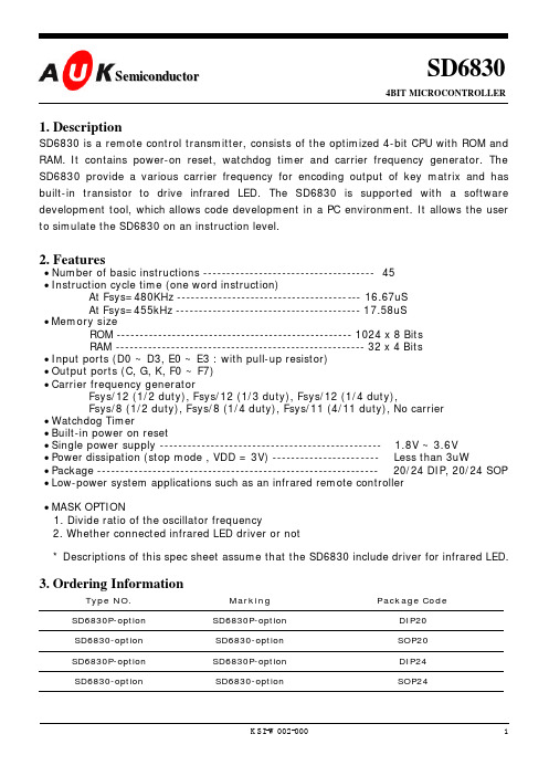
1. DescriptionSD6830 is a remote control transmitter, consists of the optimized 4-bit CPU with ROM and RAM. It contains power-on reset, watchdog timer and carrier frequency generator. The SD6830 provide a various carrier frequency for encoding output of key matrix and has built-in transistor to drive infrared LED. The SD6830 is supported with a software development tool, which allows code development in a PC environment. It allows the user to simulate the SD6830 on an instruction level.2. Features• Number of basic instructions ------------------------------------- 45 • Instruction cycle time (one word instruction)At Fsys=480KHz ---------------------------------------- 16.67uS At Fsys=455kHz ---------------------------------------- 17.58uS • Memory sizeROM --------------------------------------------------- 1024 x 8 Bits RAM ------------------------------------------------------ 32 x 4 Bits • Input ports (D0 ~ D3, E0 ~ E3 : with pull-up resistor) • Output ports (C, G, K, F0 ~ F7) • Carrier frequency generatorFsys/12 (1/2 duty), Fsys/12 (1/3 duty), Fsys/12 (1/4 duty),Fsys/8 (1/2 duty), Fsys/8 (1/4 duty), Fsys/11 (4/11 duty), No carrier • Watchdog Timer• Built-in power on reset• Single power supply ------------------------------------------------ 1.8V ~ 3.6V • Power dissipation (stop mode , VDD = 3V) ----------------------- Less than 3uW• Package ------------------------------------------------------------- 20/24 DIP, 20/24 SOP • Low-power system applications such as an infrared remote controller• MASK OPTION1. Divide ratio of the oscillator frequency2. Whether connected infrared LED driver or not * Descriptions of this spec sheet assume that the SD6830 include driver for infrared LED.3. Ordering InformationType NO.Marking Package CodeSD6830P-option SD6830P-option DIP20SD6830-option SD6830-option SOP20SD6830P-option SD6830P-option DIP24SD6830-optionSD6830-optionSOP24SD68304BIT MICROCONTROLLERS e m i c o n d u c t o r4. Block DiagramFigure 4-1 Block Diagram of the SD68305. PIN Assignment and Description5.1 PIN Assignment for 24PINS( DIP24, SOP24)Figure 5-1. Pin Assignment of 24 Pins5.2 PIN Description for 24 PINSSymbolPin No.I /OFunctions I/O TypeVDD 24-Power Supply VSS 1-GroundTEST 22INPUT Input for test ( Normally connected to VSS )OSCin 2INPUT Input for oscillating OSCout 3OUTPUT Output for oscillatingC/REM 23OUTPUT 1-Bit output for remote transmissionB D0 - D3 5 ~ 8INPUT 4-Bit input for key sense ( with pull-up resistor )A E0 - E39 ~ 12INPUT 4-Bit input for key sense ( with pull-up resistor )A F0 - F720 ~ 13OUTPUT 1-Bit individual output for key scan C G 4OUTPUT 1-Bit output D K21OUTPUT1-Bit outputD5.3 PIN Assignment for 20PINS( DIP20, SOP20)Figure 5-3. Pin Assignment of 20Pin5.4 PIN Description for 20 PINSSymbolPin No.I /OFunctions I/O TypeVDD 20-Power Supply VSS 1-GroundTEST 18INPUT Input for test ( Normally connected to VSS )OSCin 2INPUT Input for oscillating OSCout 3OUTPUT Output for oscillatingC/REM 19OUTPUT 1-Bit output for remote transmissionB D0 - D3 4 ~ 7INPUT 4-Bit input for key scan ( with pull-up resistor )A E0 – E18 ~ 9INPUT 2-Bit input for key scan ( with pull-up resistor )A F0 – F616 ~ 10OUTPUT 1-Bit individual output for key scan C K17OUTPUT1-Bit outputD5.5 I/O CIRCUIT SCHEMATICSFigure 5-5. I/O Circuit SchematicsNOTE : If STOP mode is specified, the TYPE C output becomes "L" state and the TYPE B output becomes floating state, the TYPE D output maintains previous state.ΤΨΠΕ ΑΤΨΠΕ ΒΤΨΠΕ ∆ΤΨΠΕ ΧNote : If STOP mode is specified, the TYPE C output becomes “L” state and the TYPE B output becomes floating state, the TYPE D output maintains previous state6. Basic Function Block6.1 Program Counter (PC)Program counter is used to indicate the address of the next instruction to be executed.The 10-bit program counter consists of two registers, PCH (4-bit) and PCL(6-bit).This is a polynomial counter.6.2 Program Memory (ROM)Program memory is used to store user-specified program. This consists of a 1024 x 8-bit.It is organized in 16 pages and each page is 64 bytes long. For page-in addressing, all instructions excluding JMPL and CALL can be executed by page. In order to execute jump or call in page, JMP or CAL is suitable. For page-to-page addressing, JMPL or CALL must be used.6.3 Data Memory (RAM)Data memory is used to store various type of processing data. This consists of a 32-nibble, which is organized into two files of 16 nibbles each. RAM addressing is indirectly implemented by a two registers; H, L. It’s upper 1-bit register (H) selects one of two files and its lower 4-bit register (L) selects one of 16 nibbles in the selected file.Figure 6-2. Data Memory Map6.4 Stack Register (SK)Stack register is used to store return address and provide a particularly mechanism for transferring control between programs. Two level hardware push/pop stacks are manipulated by CAL, CALL, and RET instructions. CAL/CALL instructions push the current program counter value, incremented by “1”, into stack level 1. Stack level 1 is automatically pushed to level 2.If more than two subsequent CAL/CALL are executed, only the most recent two return addresses are stored. RET instruction load the contents of stack level 1 into the program counter while stack level 2 gets copied into level 1. If more than two subsequent RET are executed, the stack will be filled with the address previously stored in level 2.6.5 Arithmetic and Logic Unit (ALU)This unit is used to perform arithmetic and logical operations such as addition, comparison, and bit manipulation.6.6 Carry Flag (CY)The carry flag contains the carry generated by the arithmetic and logical unit immediately after an operation. The set carry (SETB CY) and clear carry (CLRB CY) instructions allow direct access for setting and clearing this flag.6.7 Skip Flag (SF)The skip flag is a 1-bit register, which enables programs to conditionally skip an instruction. All instructions are executed when this flag is , the program executes NOP instruction and resets SF to “0”. Then program execution proceeds.The following instructions affect the skip flagInstructions Set conditions of SFArithmeticADD nINC LIf carry occurs(L) = 0CompareIF0 @HL.bIF0 CYIFEQU @HLIFEQU nM[HL].b = 0(CY) = 0(A) = M[HL].b(A) = nData Transfer STA @HL+XCH @HL+(L) = 0(L) = 0The instructions, which doesn t affect the skip flag but have a skip condition, are as follows.Instructions Skip conditionsData Transfer LDA nLDL nIf it is continuous, skip next sameinstruction.If it is continuous, skip next sameinstruction.Bit Manipulate SETB HCLRB HIf SETB H or CLRB H are continuous,skip nextSETB H or CLRB H instruction.6.8 RegistersRegister ARegister A, called the accumulator, plays a central role, is used to store an input or an output operand (result) in the execution of most instructions. It consists of 4-bit.Register BRegister B is used to store a temporary data in CPU. It consists of 4-bit.Register HRegister H is used to indicate an address of the data memory in conjunction with register L. It consists of 1-bit, which is related with the bit 0 of accumulatorRegister LRegister L is used to indicate an address of the data memory in conjunction with register H, Also lower 3-bit can be used to indicate the bit position of the port F. It consists of 4-bitRegister ZRegister Z is used to select a carrier frequency. The carrier frequency must be selected before Port C data write operation. It consists of 3-bit.Register ZCarrier frequencyBit 2Bit 1Bit 0/12, 1/2 duty000FSYS001F/12, 1/3 dutySYS/12, 1/4 duty010FSYS/8, 1/2 duty011FSYS100F/8, 1/4 dutySYS/11, 4/11 duty101FSYS110 No carrier111 No carrier6.9 I /O PortsPort C/REMPort C/REM is a 1-bit output port, which is related with the bit 3 of accumulator, with CMOS N-channel open drain, which have large current sink capability, for I.R.LED drive.This output can be configured as carrier frequency by programming the register Z and port C data. This pin is put into the high-impedance state in stop mode.Port DPort D is a 4-bit input port with pull-up resistor. Forcing any input pins to “L” state, system reset occurs and it starts to operate from the reset address.Port EPort E is a 4-bit input port with pull-up resistor. Forcing any input pins toreset occurs and it starts to operate from the reset address.Port FPort F is an 8-bit output port with N-channel open drain. Each output which specified by the lower 3-bit of register L can be set and reset individually. All F pins are put into the low state in stop mode.Port GPort G is a 1-bit output port with N-channel open drain. When stop mode is specified, this pin still remains in the previous state. Set this pin to appropriate state before enteringstop mode for visible LED or key scan application.Port KPort K is a 1-bit output port with N-channel open drain. When stop mode is specified, this pin still remains in the previous state. Set this pin to appropriate state before entering stop mode for visible LED or key scan application.6.10 Carrier frequency generatorOne of seven carrier frequencies can be selected and transmitted through the C/REM pin by programming the register Z and port C.Figure 6-3 PORT C/REM and Carrier Output6.11 Watchdog timer (WDT)The watchdog timer provides the means to return to a reset condition when a system malfunction occurs and the program enters an infinite loop caused by noise or any abnormal state.Also this timer have a function of oscillation stabilization timer. This is a 13-bit counter,counts the clock which is divided twelve (F SYS /12). In the stop mode the oscillation circuit stops but when a key input is detected (Port D, Port E) oscillation starts. When 12288 clock cycles have been counted, the program will be executed from reset address (000H). If the port C data register ’s value does not change from “L” to “H” before the timer counts 98304clock cycles, a device reset condition is generated.The oscillator stabilization time : 12/F SYS * 210 = 1/F SYS * 12288 = 27mS (@455KHz)The time-out period : 12/F SYS * 213 = 1/F SYS * 98304 = 216mS (@455KHz)Figure 6-4. Function of Watchdog Timer6.12 Power-on resetThe SD6830 incorporates an on-chip power-on reset circuitry which provides internal chip reset for most power-up situations. The power-on reset circuit and the watchdog timer are closely related. On power-up the power-on reset circuit is active and watchdog timer is reset. After the reset time, which is in proportion to the rate of rise of VDD, watchdog timer begins counting. After the oscillator stabilization time, which is typically 27mS in F SYS =455KHz, program execution proceeds from reset address (000H).Figure 6-5. Built-in Power-on Reset6.13 Stop modeThe SD6830 support the stop mode to reduce power consumption. This mode is entered when the STOP instruction is executed during key inputs are not active. Activating any key inputs (Port D, Port E) the device is awakened from stop mode and restarts to operate from reset address. When the device is released from stop mode, following module set to appropriate value in reset routine: PORT G and PORT K.In stop mode, the oscillator is stopped and the each port state is as follows.Port C/REM become inactive state. ( for including I.R.LED driver,after the reset release)Port G and Port K retain previous state.VDDVSSInternal /PORDMC68307pF2MohmRESET TIME1.8V 0.3VDDVDD VDD PINInternal/PORSD6830Figure 6-6. Rest structure and Release Timing for STOP Mode to Normal Mode6.14 OSC Divide OptionThe OSC divide option provides a maximum 1MHz system clock (F SYS ). F OSC which is generated in oscillation circuit is divided eight or non-divide to produce F SYS .This dividing ratio will be selected by mask option.F OSC : Oscillator clock, F SYS : System clock (F OSC or F OSC /8)Figure 6-7 OSC Divide Option7. Electrical Specifications 7.1 Absolute maximum ratingsSymbolsParametersConditionsRatingsUnitsV DD Supply Voltage -0.3 ~ 6.0V V I Input Voltage -0.3 ~ V DD + 0.3V V O Output Voltage Ta=25¡É-0.3 ~ V DD + 0.3V T OPR Operating temperature --20 ~ 85¡ÉT STGStorage Temperature--40 ~ 125¡É7.2 Recommended operating conditions(V DD = 3V ± 10%, Ta=-20 ~ 70¡É, unless otherwise noted)SymbolsParametersMin.Typ.Max.UnitsV DD Supply Voltage1.8 3.6V V IH1"H" input Voltage, all input pinsexcept OSCIN0.7V DD V DD V DD -V V IH2"H" input Voltage, OSCIN V DD -0.3V DD V DD V V IL1"L" input Voltage, all input pinsexcept OSCIN000.3 V DDV V IL2"L" input Voltage, OSCIN 000.3V Non-divide option 2501000KHz F OSCOscillating frequencyDivide-8 option26MHz7.3 Electrical characteristics(V DD = 3V ± 10%, Ta= 25¡É, unless otherwise noted)SymbolsParametersTest ConditionsMin.Typ.Max.Units250KHz¡ÂF OSC ¡Â3.9MHz 1.8 3.0 3.6V V DD Supply Voltage 3.9MHz¡ÂF OSC ¡Â6.0MHz 2.2 3.0 3.6V I OH "H" output current V O = 2.0V, Port C -6-9-14mA I OL0"L" output currentV O = 0.4V, Port C 1.53 4.5mA I OL1V O = 0.4V, Port C180210240mA I OL2V O = 0.4V, Port F 0.5 1.0 2.0mA I OL3"L" output currentV O = 0.4V, Port G/K 1.5 3.0 4.5mA I LIH1V I = V DD , Port D/E --3§ËI LIH2"H" input leakage current V I = V DD , OSCIN -310§ËI LIL "L" input leakage current V I = V SS , OSCIN -0.6-3-10§ËI LOH "H"output leakage current V O = V DD , Port C/F/G/K --1§ËR PULL-UPPull-up resistance of input Port V I = 0V, V DD =3V3070150K §ÙI DD Supply current at normal mode 0.51.0mA I DDS Supply current at stop mode 1.0§ËF SYS Clock frequency 2501000KHz Non-divide option 2501000KHz F OSCOscillator frequencyDivide-8 option26MHz8. Packing Outlines and Dimensions9. Instructions9.1 Symbol DescriptionSYMBOL DESCRIPTIONSA ,B , L 4 Bit RegisterH 1-Bit RegisterZ 3-Bit RegisterPCH The Higher 4-Bit of the Program CounterPCL The Lower 6-Bit of the Program CounterPC 10-Bit Program Counter ( Consisting of the PCH and PCL )SK 10-Bit Stack RegisterCY 1-Bit Carry FlagSF 1-Bit Skip FlagC, G, K 1-Bit PortD, E 4-Bit PortF 8-Bit Port¡ç Direction of Data FlowM[(HL)] or @HL The Contents of Data Memory Addressed by Reg HLM[(HL)].b or @HL.b The Specified Bit’s Content of Data Memory Addressed by Reg HL @HL+ As a result of execution, increment L by oneaddr Addressn immediate data9.2 Opcode Map9.3 Instruction DescriptionsADD nBinary code : 0110xxxxSyntax : [<label>] ADD nOperation : (A) ¡ç (A) + n, n=0~15 ( n must be decimal number )Flags : CY: Unaffected. SF: Set to one if carry occurs, cleared otherwise. Words/Cycles : 1/1Description : Adds an immediate data to the accumulator and stores the result in the accumulate.Example : ADD 8 ; Add 8 to A.JMP 035 ; Jump to 035 if 0¡ÂA¡Â7JMP 05F ; Jump to 05F if 8¡ÂA¡Â15ADDC @HLBinary code 00010000Syntax : [<label>] ADDC @HLOperation : (A) ¡ç (A) + M[(HL)] + (CY), (CY) ¡ç CarryFlags : CY: Set on carry-out of (A) + M[(HL)] + (CY)SF: UnaffectedWords/Cycles : 1/1Description : Adds the contents of the accumulator, the contents of data memoryaddressed by registers H and L, and the carry bit. It stores the result in the accumulator and the carry flag.Example : CLRB CY ; Clear CY to zeroLDA 5 ; Load 5 to ACLRB H ; Clear H to zeroLDL 6 ; Load 6 to LADDC @HL ; Add the content of A, M[(06)], and the content of CY CAL addrBinary code : 11xxxxxxSyntax : [<label>] CAL addrOperation : (SK1) ¡ç (SK0), (SK0) ¡ç (PC) + 1, (PCL) ¡ç addr, addr = 000 ~ 03F ( addr must be hexadecimal number )Flags : CY: Unaffected SF: UnaffectedWords/Cycles : 1/1Description : Calls a subroutine located at the indicated address and pushes the current contents of the program counter to the top of stack. The indicated address must be within the current page.Example : CAL 100 : Call subroutine located at the 100. The 100 must be logical address and within the current page.CALL addrBinary code : 010100xx xxxxxxxxSyntax : [<label>] CALL addrOperation : (SK1) ¡ç (SK0), (SK0) ¡ç (PC) + 1, (PC) ¡ç addr, addr = 000 ~ 3FF ( addr must be hexadecimal number ) Flags : CY: UnaffectedSF: UnaffectedWords/Cycles : 2/2Description : Calls a subroutine located at the indicated address and pushes thecurrent contents of the program counter to the top of stack. Theindicated address can be anywhere in the full 1Kbyte memory space. Example : CALL 2FF ; Call subroutine located at the 2FF.The 2FF must be logical address.CLRB @HL.bBinary code : 010110xxSyntax : [<label>] CLRB @HL.bOperation : M[(HL)].b ¡ç 0Flags : CY: UnaffectedSF: UnaffectedWords/Cycles : 1/1Description : Clears the specified bit of data memory addressed by registers H and L to zero.Example : CLRB H ; Clear H to 0LDL 10 ; Load 10 to L. The 10 must be decimal number.CLRB @HL.0 ; Clear the bit 0 of M[(0A)] to 0.CLRB CYBinary code : 00001000Syntax : [<label>] CLRB CYOperation : (CY) ¡ç 0Flags : CY: Set to zeroSF: UnaffectedWords/Cycles: 1/1Description : Clears the carry flag to zero.Example : CLRB CY ; Clear CY to zeroBinary code : 00001010Syntax : [<label>] CLRB FOperation : F.(L) ¡ç 0Flags : CY: Unaffected SF: UnaffectedWords/Cycles : 1/1Description : Clears the specified bit of port F addressed by the lower 3-bit of register L to zero.Example : LDL 13 ; Load 13 to LCLRB F : Clears the bit 5 of F to zeroCLRB GBinary code : 00101100Syntax : [<label>] CLRB GOperation : G.(L) ¡ç 0Flags : CY: UnaffectedSF: UnaffectedWords/Cycles : 1/1Description : Clears the port G to zero.Example : CLRB G ; Clear G to zeroCLRB HBinary code : 00100100Syntax : [<label>] CLRB HOperation : (H) ¡ç 0Flags : CY: UnaffectedSF: UnaffectedWords/Cycles : 1/1Description : Clears the contents of register H to zero. Skip this instruction if it orSETB H was used just before.Example : IFEQU 1CLRB H ; Clear H to zero and skip continuous SETB H/CLRB H, if (A)¡Á1SETB H ; Sets H to one and skip continuous SETB H/CLRB H, if (A)=1Binary code : 00101110Syntax : [<label>] CLRB KOperation : (K) ¡ç 0Flags : CY: UnaffectedSF: UnaffectedWords/Cycles : 1/1Description : Clears the port K to zero.Example : CLRB K ; Clear K to zero.IF0 @HL.bBinary code : 000001xxSyntax : [<label>] IF0 @HL.bOperation : M[(HL)b] = 0Flags : CY: UnaffectedSF: Set to one if equal, cleared otherwiseWords/Cycles : 1/1Description : Compares the specified bit of data memory addressed by registers H and L with zero.Example : SETB H ; Set H to oneLDL 4 ; Load 4 to LIF0 @HL.3 ; Compare the bit 3 of M[(14)] with zeroJMP 020 ; Jump to 020 if not equalJMP 030 ; Jump to 030 if equalIF0 CYBinary code : 00011100Syntax : [<label>] IF0 CYOperation : (CY) = 0Flags : CY : UnaffectedSF : Set to one if equal, cleared otherwiseWords/Cycles : 1/1Description : Compares the carry flag with zero.Example : IF0 CY ; Compare the content of CY to zeroJMP 030 ; Jump to 030 if not equalJMP 040 ; Jump to 040 if equalIFEQU @HLBinary code : 00001111Syntax : [<label>] IFEQU @HLOperation : (A) = M[(HL)]Flags : CY : UnaffectedSF : Set to one if equal, cleared otherwiseWords/Cycles : 1/1Description : Compares the contents of accumulator with the contents of datamemory addressed by registers H and L.Example : LDA 14 ; Load 14 to A, and 14 must be decimal numberSETB H ; Sets H to oneLDL 4 ; Loads 4 to LIFEQU @HL ; Compares 14 with M[(14)]JMP 050 ; Jump to 050 if not equalJMP 060 ; Jump to 060 if equalIFEQU nBinary code : 00001110 0111xxxxSyntax : [<label>] IFEQU nOperation : (A) = n, n = 0 ~15 ( n must be decimal number )Flags : CY: UnaffectedSF: Set to one if equal, cleared otherwiseWords/Cycles : 2/2Description : Compares the contents of accumulator with an immediate data. Example : IFEQU 15 ; Compare the contents of accumulator with 15JMP 070 ; Jump to 070 if not equalJMP 080 ; Jump to 080 if equalINC LBinary code : 00100010Syntax : [<label>] INC LOperation : (L) ¡ç (L) + 1Flags : CY : Unaffect SF:As a result of execution, set to one if the contents of register L are zero, cleared otherwise.Words/Cycles : 1/1Description : The contents of register L are incremented by one.Example : LDL 14 ; Load 14 to LINC L ; The contents of L are incremented by oneINC L ; The contents of L are incremented by oneJMP 090 ; It is skipped because the contents of L isJMP 0A0 ;Jump to 0A0JMP addrBinary code : 10xxxxxxSyntax : [<label>] JMP addrOperation : (PCL) ¡ç addr, addr = 00 ~ 3F ( addr must be hexadecimal number ) Flags : CY : UnaffectedSF : UnaffectedWords/Cycles : 1/1Description : Jumps unconditionally to the indicated address. The indicated address must be within the current page.Example : JMP 2EF ; Jump unconditionally to the 2EF. The 2EF address must be within the current page.JMPL addrBinary code : 010101xx xxxxxxxxSyntax : [<label>] JMPL addrOperation : (PC) ¡ç addr, addr = 000 ~ 3FF (addr must be hexadecimal number. ) Flags : CY : UnaffectedSF : UnaffectedWords/Cycles:2/2Description : Jumps unconditionally to the indicated address. The indicated address can be anywhere in the full 1K-byte memory space.Example : JMPL 100 ; Jump unconditionally to 100LDA @HLBinary code : 00100011Syntax : [<label>] LDA @HLOperation : (A) ¡ç M[(HL)]Flags : CY : UnaffectedSF : UnaffectedWords/Cycles: 1/1Description : Loads the contents of memory addressed by registers H and L into the accumulator.Example : SETB H ; Set H to 1LDL 0 ; Load 0 to LLDA @HL ; Load M[(10)] into ABinary code : 0111xxxxSyntax : [<label>] LDA nOperation : (A) ¡ç n, n=0~15 ( n must be decimal number. )Flags : CY : UnaffectedSF : UnaffectedWords/Cycles : 1/1Description : Loads an immediate data into the accumulator. Skip this instruction if it was used just before.Example : STA BLDA 15 ; Load 15 into A.LDA 4 ; It is skipped because this instruction was used just before LDA 7 ; It is skipped because this instruction was used just before JMP 0B0 ; Jump to 0B0LDA BBinary code : 00010101Syntax : [<label>] LDA BOperation : (A) ¡ç (B)Flags : CY : UnaffectedSF : UnaffectedWords/Cycles : 1/1Description : Loads the contents of register B into the accumulator.Example : LDA B ; Load the contents of B into ALDA DBinary code : 00010100Syntax : [<label>] LDA DOperation : (A) ¡ç (D)Flags : CY : UnaffectedSF : UnaffectedWords/Cycles : 1/1Description : Loads the contents of port D into the accumulator.Example : LDA D ; Load the contents of D into ABinary code : 00010010Syntax : [<label>] LDA EOperation : (A) ¡ç (E)Flags : CY : UnaffectedSF : UnaffectedWords/Cycles : 1/1.Description : Loads the contents of port E into the accumulatorExample : LDA E ; Load the contents of E into ALDA HBinary code : 00010001Syntax : [<label>] LDA HOperation : (A) ¡ç (H)Flags : CY : UnaffectedSF : UnaffectedWords/Cycles:1/1Description : Loads the contents of register H into the bit 0 of accumulator. Example : LDA H ; Load the content of H into the bit 0 of ALDA LBinary code : 00010110Syntax : [<label>] LDA LOperation : (A) ¡ç (L)Flags : CY : UnaffectedSF : UnaffectedWords/Cycles : 1/1Description : Loads the contents of register L into the accumulator.Example : LDA L ; Load the contents of L into ABinary code : 0100xxxxSyntax : [<label>] LDL nOperation : (A) ¡ç n, n = 0 ~ 15 ( n must be decimal number )Flags : CY : UnaffectedSF : UnaffectedWords/Cycles : 1/1Description : Loads an immediate data to the register L. Skip this instruction if it was used just before.Example : LDA 3LDL 8 ; Load 8 to LLDL 4 ; It is skipped because this instruction was used just before JMP 0C0 ; Jump to 0C0LDZ nBinary code : 00110xxxSyntax : [<label>] LDZ nOperation : (A) ¡ç n, n = 0 ~ 7 ( n must be decimal number )Flags : CY : UnaffectedSF : UnaffectedWords/Cycles: 1/1Description : Load an immediate data into the register Z.Example : LDZ 0 ; Load 0 into Z. The 0 must be decimal numberNOPBinary code : 00000000Syntax : [<label>] NOPOperation : (PC) ¡ç (PC) + 1Flags : CY : UnaffectedSF : UnaffectedWords/Cycles: 1/1Description : No operation.Example : NOP ; No operationBinary code : 00010111Syntax : [<label>] NOTOperation : (A) ¡ç /(A)Flags : CY : UnaffectedSF : UnaffectedWords/Cycles: 1/1Description : The contents of accumulator are 1Example : LDA 7NOT ; 1’s complement 7, then leaves 8 in ARETBinary code : 00011101Syntax : [<label>] RETOperation : (PC) ¡ç (SK0), (SK0) ¡ç (SK1)Flags : CY: UnaffectedSF: UnaffectedWords/Cycles: 1/1Description : Returns from the subroutine to main routine.Example : RET ; Returns from the subroutine to main routineRRCBinary code : 00010011Syntax : [<label>] RRCOperation : (A.b) ¡ç (A.b+1) (A.3) ¡ç (CY) (CY) ¡ç (A.0)Flags : CY : Set to bit 0 of the accumulatorSF : UnaffectedWords/Cycles:1/1Description : Shifts the contents of accumulator 1-bit to the right through the carry.The carry bit content shifts into the bit 3 of accumulator, and the bit 0 ofaccumulator is shifted into the carry bit.Example : SETB CY ; Set CY to one.LDA 5 ; Load 5 to ARRC ; CY becomes zero, and the contents of A is 11SETB @HL.bBinary code : 010111xxSyntax : [<label>] SETB @HL.bOperation : M[(HL)].b ¡ç 1Flags : CY : UnaffectedSF : UnaffectedWords/Cycles: 1/1Description : Sets the specified bit of memory addressed by registers H and L to one. Example : CLRB H ; Clear H to zeroLDL 5 ; Load 5 to LSETB @HL.2 ; Set the bit 2 of M[(05)] to oneSETB CYBinary code : 00001001Syntax : [<label>] SETB CYOperation : (CY) ¡ç 1Flags : CY : Set to oneSF : UnaffectedWords/Cycles: 1/1Description : Sets the contents of carry flag to one.Example : SETB CY ; Sets the content of CY to oneSETB FBinary code : 00001011Syntax : [<label>] SETB FOperation : F.(L) ¡ç 1Flags : CY : UnaffectedSF : UnaffectedWords/Cycles: 1/1Description : Sets the specified bit of the port F addressed by register L to one. Example : LDL 4 ; Loads 4 to LSETB F ; Sets the bit 4 of F to one。
迪亚戈考场手机信号屏蔽器功能参数介绍
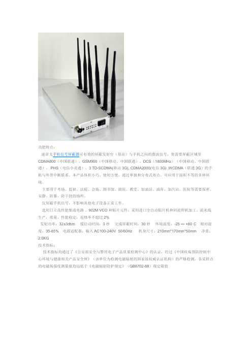
功能特点:
迪亚戈手机信号屏蔽器可有效的屏蔽发射台(基站)与手机之间的微波信号,使需要屏蔽区域里CDMA800(中国联通)、GSM900(中国移动、中国联通)、DCS(1800MHz)(中国移动、中国联通)、 PHS (电信小灵通)、3 TD-SCDMA(移动3G), CDMA2000(电信3G) ,WCDMA(联通3G)的手机与外界中断联系。
本产品体积小巧、使用方便,通过单独和分布式布点,可应用于面积不等的多种环境。
主要用于考场、监狱、法庭、会场、图书馆、剧院、教堂、加油站、油库、加汽站、医院等需要保密、安静、防暴、防干扰的场所。
仅屏蔽手机信号,不影响其他电子设备正常工作。
选用日立高性能集成电路、902M VCO和贴片元件,采用进口全自动贴片机和回流焊机加工、流水线生产,质量、性能稳定,返修率不超过2%
发射功率:32±3dbm 缓启动时间:3秒完成屏蔽时间:30秒环境温度:-25 ― +60°C相对湿度:35-85%电源适配器:输入AC100-240V 50/60Hz机身尺寸:210mm*170mm*50mm 净重:2.0KG 技术指标:
技术指标均通过了《公安部安全与警用电子产品质量检测中心》的认证,经过《中国疾病预防控制中心环境与健康相关产品安全所》(该单位为检测电磁辐射的国家级权威认证机构)的严格检测,各采样点的电磁场强度测量值均远低于《电磁辐射防护规定》(GB8702-88)规定限值。
AT6832 电容漏电测试仪 用户手册说明书

AT6832用户手册@Instrumets常州安柏精密仪器有限公司江苏省常州市天宁区兰陵荡南工业园5楼[213014]电话:*************/89966117/89966227/400-600-1217传真:*************销售服务电子邮件: *****************技术支持电子邮件: ****************©2005-2009 Applent Instruments, Inc.当你发现有以下不正常情形发生,请立即终止操作并断开电源线。
立刻与安柏科技销售部联系维修。
否则将会引起火灾或对操作者有潜在的触电危险。
●仪器操作异常。
●操作中仪器产生反常噪音、异味、烟或闪光。
●操作过程中,仪器产生高温或电击。
●电源线、电源开关或电源插座损坏。
●杂质或液体流入仪器。
为避免可能的电击和人身安全,请遵循以下指南进行操作。
免责声明声明:!, $, #,标志和文字是常州安柏精密仪器有限公司已经或正在申请的商标。
有限担保和责任范围 3常州安柏精密仪器有限公司(以下简称Applent)保证您购买的每一台AT6832在质量和计量上都是完全合格的。
此项保证不包括保险丝以及因疏忽、误用、污染、意外或非正常状况使用造成的损坏。
本项保证仅适用于原购买者,并且不可转让。
自发货之日起,Applent提供玖拾(90)天保换和叁年免费保修,此保证也包括VFD或LCD。
玖拾天保换期内由于使用者操作不当引起的损坏,保换条款终止。
贰年包修期内由于使用者操作不当而引起仪器损坏,维修费用由用户承担。
贰年后直到仪表终生,Applent将以收费方式提供维修。
对于VFD或LCD的更换,其费用以当前成本价格收取。
如发现产品损坏,请和Applent取得联系以取得同意退回或更换的信息。
之后请将此产品送销售商进行退换。
请务必说明产品损坏原因,并且预付邮资和到目的地的保险费。
对保修期内产品的维修或更换,Applent将负责回邮的运输费用。
AC DC 电流探头BTN菜单指南说明书
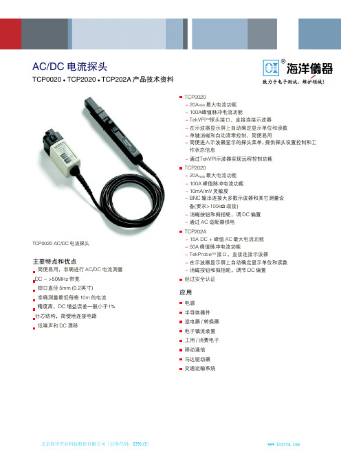
AC/DC 电流探头-TCP0020TCP2020 TCP202AAC/DC 电流探头TCP0020 TCP2020 TCP202A 产品技术资料TCP0020-20A RMS 最大电流功能-100A峰值脉冲电流功能-TekVPI TM 探头接口,直接连接示波器-在示波器显示屏上自动确定显示单位和读数-单键消磁和自动清零控制,简便易用-简便进入示波器显示的探头菜单,提供探头设置控制和工作状态信息-通过TekVPI示波器实现远程控制功能TCP2020-20A RMS 最大电流功能-100A 峰值脉冲电流功能-10mA/mV 灵敏度-BNC 输出连接大多数示波器和其它测量设备(要求>100k Ω 端接)-消磁按钮和拇指轮,调 DC 偏置-通过 AC 适配器供电 TCP202A-15A DC + 峰值 AC 最大电流功能-50A 峰值脉冲电流功能-TekProbe TM 接口,直接连接示波器-在示波器显示屏上自动确定显示单位和读数-消磁按钮和拇指轮,调节 DC 偏置 经过安全认证应用电源 半导体器件 逆电器/转换器 电子镇流装置 工用/消费电子 移动通信 马达驱动器 交通运输系统主要特点和优点简便易用,准确进行 AC/DC 电流测量 DC - >50MHz 带宽钳口直径 5mm (0.2英寸)准确测量最低每格 10m 的电流 精度高,DC 增益误差一般小于1%分芯结构,简便地连接电路 低噪声和 DC 漂移TCP0020 AC/DC 电流探头产品技术资料TCP0020、TCP2020、TCP202ATCP0020、TCP2020和TCP202A是简便易用的高性能AC/DC 电流探头家族,设计用于各种示波器。
TCP0020设计采用TekVPI TM探头接口直接连接示波器,TCP202A设计采用TekProbe TM探头接口直接连接示波器。
TCP2020设计用于带有BNC输入及>100 kΩ输入端接的任何仪器。
PMC-851X综合保护测控装置用户说明书_V1.5_131014
海康威视 F202 AC-16 0.01 残余流保护断路器商品介绍说明书

Instantaneous AC type 10 mA 16 A 2
at Rated Operating Conditions per Pole 1.5 W 230/400 V 50...60 Hz
Operation -25...55 °C
F202 AC-16/0,01
Dimensions
Product Net Width Product Net Height Product Net Depth / Length Product Net Weight
0.035 m 0.085 m 0.069 m
0.200 kg
Container Information
Package Level 1 Units Package Level 1 Width Package Level 1 Height Package Level 1 Depth / Length Package Level 1 Gross Weight Package Level 1 EAN
1 piece 0.041 m 0.078 m 0.096 m
0.225 kg
8012542779902
Ordering
Minimum Order Quantity Customs Tariff Number
1 pieceons (Document Number)
Long Description
Technical
Standards
Operating Characteristic Type of Residual Current Rated Residual Current Rated Current (In) Number of Poles Power Loss Rated Voltage (Ur) Rated Frequency (f)
FDMF6833C;中文规格书,Datasheet资料

April 2012
FDMF6833C — Extra-Small, High-Performance, High-Frequency DrMOS Module
Features
Over 93% Peak-Efficiency High-Current Handling: 50A High-Performance PQFN Copper-Clip Package 3-State 5V PWM Input Driver Skip-Mode SMOD# (Low-Side Gate Turn Off) Input Thermal Warning Flag for Over-Temperature Condition Driver Output Disable Function (DISB# Pin) Internal Pull-Up and Pull-Down for SMOD# and DISB# Inputs, Respectively Fairchild PowerTrench® Technology MOSFETs for Clean Voltage Waveforms and Reduced Ringing Fairchild SyncFET™ (Integrated Schottky Diode) Technology in Low-Side MOSFET Integrated Bootstrap Schottky Diode Adaptive Gate Drive Timing for Shoot-Through Protection Under-Voltage Lockout (UVLO) Optimized for Switching Frequencies up to 1MHz Low-Profile SMD Package Fairchild Green Packaging and RoHS Compliance Based on the Intel® 4.0 DrMOS Standard
DS-D5022FC-C 22英寸监视器说明书
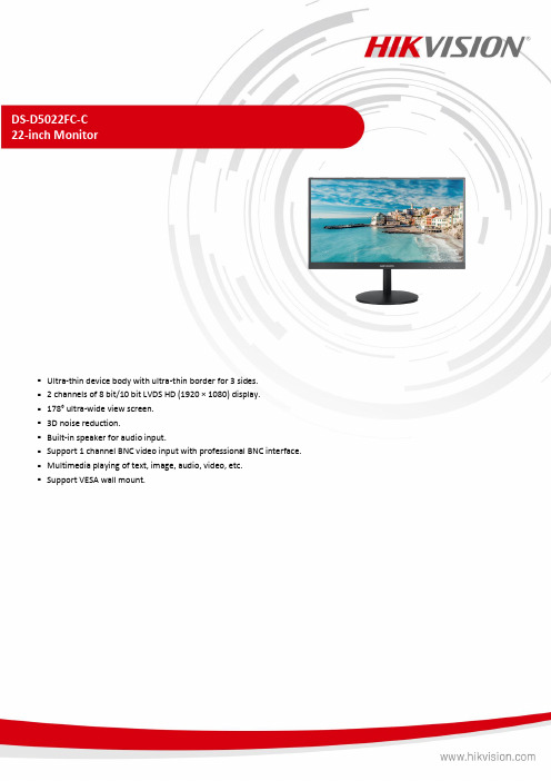
DS-D5022FC-C22-inch Monitor⏹Ultra-thin device body with ultra-thin border for 3 sides.⏹ 2 channels of 8 bit/10 bit LVDS HD (1920 × 1080) display.⏹178° ultra-wide view screen.⏹3D noise reduction.⏹Built-in speaker for audio input.⏹Support 1 channel BNC video input with professional BNC interface.⏹Multimedia playing of text, image, audio, video, etc.⏹Support VESA wall mount.SpecificationModel DS-D5022FC-CDisplay Screen Size 21.5”Active Display Area 478.656 (H) mm × 260.28 (V) mm Resolution 1920 × 1080Backlight E-LEDPixel Pitch 0.241 (H) mm × 0.241 (V) mm Brightness 250 cd/m2Viewing Angle 178° (H) / 178° (V)Color Depth 8 bit, 16.7 MContrast Ratio 3000:1Response Time 6.5 msRefresh Rate 60 HzHaze Haze 25%, 3 HReliability 7 × 18 HColor Gamut 72% NTSCPower Power Supply 100 to 240 VAC, 50/60 Hz Power Consumption ≤ 22 WStandby Consumption ≤ 0.5 WWorking Environment Working Temperature 0 °C to 40 °C (32 °F to 104 °F) Working Humidity 20% to 90% RH (non-condensing) Storage Temperature –20 °C to 60 °C (–4 °F to 140 °F) Storage Humidity 5% to 90% RH (non-condensing)General Casing Material PlasticVESA 75 mm × 75 mm, 4-M6 × 6 screw holesBezel Width 1.88 mm (top/left/right), 19 mm (bottom)Product Dimensions(W × H × D)With base: 492.356 (W) mm × 390.11 (H) mm × 200.20 (D) mm (19.38'' × 15.36'' ×7.88'')Without base: 492.356 (W) mm × 289.680 (H) mm × 43.88 (D) mm (19.38'' × 11.40'' ×1.73'')Package Dimensions(W × H × D)647 (W) mm × 111 (H) mm × 406 (D) mm (25.49'' × 4.37'' × 15.99'')Net Weight 2.6 ± 0.5 kg (5.7 ± 1.1 lb.)Gross Weight 3.8 ± 0.5 kg (8.4 ± 1.1 lb.)Packing ListMonitor × 1, AC power cable × 1, base bracket × 1, user manual × 1, quick start guide× 1, HDMI cable × 1Remarks*The base is included by default.*The product appearance and parameters in this specification may vary from youractual device. Please consult our local sales staff for further information.Interface Video & Audio Input HDMI 1.4 × 1, VGA × 1, CVBS × 1, AUDIO IN × 1 Video & Audio Output Speaker (2 W, 8 Ω) × 2⏹ Physical InterfaceInterfaceDescription Interface Description VGAVGA analog signal input BNC CVBS signal input HDMIHDMI 1.4 digital signal input USB USB 2.0 AUDIO IN 3.5 mm audio input AC 100–240V~ 100 to 240 VAC, 50/60 Hz power supply⏹ Dimension⏹ Accessory⏹OptionalDS-DM1940WWall-mounted Bracket⏹ Available ModelDS-D5022FC-C。
NTC-MF52-683F3950_规格书(电池或者电机)
-54
4825.960 5089.680 5367.270 5.454 -5.181 0.733 -0.697
-53
4499.880 4742.420 4997.540 5.379 -5.114 0.729 -0.693
-52
4198.630 4421.840 4656.460 5.305 -5.047 0.725 -0.690
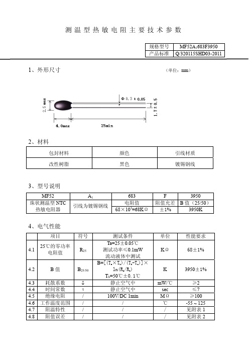
测温型热敏电阻主要技术参数
规格型号 MF52A1683F3950 产品标准 Q/320115SHD03-2011
1、外形尺寸
(单位:mm)
2、材料
包封材料 改性树脂
颜色 黑色
引线材质 镀锡钢线
3、型号说明
MF52 珠状测温型 NTC
热敏电阻器
A1 引线为镀锡钢线
683
电阻值 68×103=68KΩ
F
-11
370.336 380.575 391.058 2.754 -2.690 0.506 -0.494
-10
351.672 361.206 370.962 2.700 -2.639 0.499 -0.488
-9
334.042 342.920 351.998 2.647 -2.588 0.492 -0.481
温度(℃)
电阻(KΩ)
电阻精度(%) 温度精度(℃)
最小值 中心值 最大值 △R -△R △T -△T
-16
481.690 496.324 511.351 3.027 -2.948 0.538 -0.524
-15
456.749 470.372 484.353 2.972 -2.896 0.532 -0.518
-39
1798.690 1878.170 1960.960 4.407 -4.231 0.667 -0.640
一种自恢复LED背光短路保护电路及自恢复短路保护设备[实用新型专利]
![一种自恢复LED背光短路保护电路及自恢复短路保护设备[实用新型专利]](https://img.taocdn.com/s3/m/e0fe268758fafab068dc02cc.png)
专利名称:一种自恢复LED背光短路保护电路及自恢复短路保护设备
专利类型:实用新型专利
发明人:任好
申请号:CN201320563155.7
申请日:20130911
公开号:CN203522123U
公开日:
20140402
专利内容由知识产权出版社提供
摘要:本实用新型实施例公开了一种自恢复LED背光短路保护电路及自恢复短路保护设备,包括:LED发光电路,PWM电路,变压器T1,二极管D200,二极管D201,二极管D202,二极管
D204,稳压管ZD1,滤波电容EC201,电阻R200,电阻R201,电阻R227,电阻R224,电阻
R225,电阻R303,电阻R248,电阻R236,电阻R302,电阻R222,电源,电源VS,电源VC,电源VCC,三极管Q300,三极管Q203,三极管Q204,三极管Q206,光电耦合器U1。
采用本实用新型,具有有效防止短路造成的损坏,短路解除后自动恢复工作,满足背光LED电视短路保护的需求。
申请人:深圳市瀚强科技有限公司
地址:518000 广东省深圳市深南大道7002号财富广场A座19楼S-Z室
国籍:CN
代理机构:广州三环专利代理有限公司
更多信息请下载全文后查看。
