PyroSiM中文版用户说明书
pymo使用说明说明书

pymo (python memories off) 使用说明V1.2.0– By chen_xin_ming目录第一章pymo简介 (5)第二章A VG的组成部分和移植方法简介 (6)第三章pymo的目录结构 (7)第四章游戏配置文件解析(gameconfig.txt) (8)第五章pymo中的坐标、颜色和时间表示方法 (9)一、坐标 (9)二、颜色 (9)三、时间 (9)第六章pymo支持的图像、音频、视频格式及转换方法 (10)一、图片 (10)二、塞班版本图片的透明 (10)三、安卓、PC版本图片的透明 (13)四、音频 (13)五、视频 (14)六、pymo推荐的图片、音频格式及参数 (15)七、系统图片的参数和要求 (15)第七章制作你的第一个游戏! (17)一、素材 (17)二、脚本 (17)三、运行 (18)第八章一些脚本范例 (19)一、游戏开始界面 (19)二、选择支示例 (20)三、每次游戏开始界面显示不同的图片(使用全局变量) (21)第九章鉴赏系统的编写 (23)一、CG鉴赏 (23)二、自动生成CG鉴赏缩略图 (24)三、音乐鉴赏 (24)第十章游戏资源的打包和发布 (26)一、资源打包 (26)二、游戏发布 (26)第十一章pymo android版、PC版注意事项 (27)第十二章脚本指令说明书 (28)一、对话文字显示指令 (28)1. #say (28)2. #text (28)3. #text_off (29)4. #waitkey (29)5. #title (29)6. #title_dsp (30)二、图像相关操作指令 (30)1. #chara (30)2. #chara_cls (31)4. #bg (31)5. #flash (32)6. #quake (32)7. #fade_out (32)8. #fade_in (33)9. #movie (33)10. #textbox (33)11. #chara_quake (33)12. #chara_down (34)13. #chara_up (34)14. #scroll (34)15. #chara_y (35)16. #chara_scroll (36)17. #anime_on (36)18. #anime_off (37)19. #chara_anime (38)三、变量、选择、跳转类指令 (38)1. #set (38)2. #add (38)3. #sub (39)4. #label (39)5. #goto (39)6. #if...goto (40)7. #change (40)8. #call (40)9. #ret (41)10. #sel (41)11. #select_text (41)12. #select_var (42)13. #select_img (42)14. #select_imgs (43)15. #wait (44)16. #wait_se (44)16. #rand (44)四、声音类指令 (45)1. #bgm (45)2. #bgm_stop (45)3. #se (45)4. #se_stop (46)5. #vo (46)五、系统类指令 (46)1. #load (46)2. #album (47)4. #date (47)5. #config (48)第一章pymo简介pymo全称Python Memories Off,是由chen_xin_ming开发的一款A VG游戏引擎。
PyroMAT 系统用户指南说明书
Application Notepyrogen or bacterial endotoxin test may be used in place of the in vivo rabbit pyrogen test, where appropriate.”Principle of the MATThe monocyte activation test (MAT) is the human in vitro alternative to the rabbit pyrogen test, and allows the detection of the full range of pyrogens, including endotoxins and non-endotoxin pyrogens (NEPs).By putting the product to be tested in contact withhuman monocytic cells, it will mimic what happens in the human body: in presence of pyrogens, the monocytes are activated and produce cytokines such as interleukin-6.The cytokines are then detected using an immunological assay (ELISA) involving specific antibodies and an enzymatic color reaction.Principle of the PyroMAT™ SystemThe PyroMAT™ System uses cryo-preserved Mono-Mac-6 (MM6) human monocytic cells as a source of monocytes. The response to pyrogenic substances is determined by measurement of interleukin-6 (IL-6) produced by the Mono-Mac-6 cells. For this purpose, the ELISA microplate supplied in the kit is coated with an antibody specific to IL-6.IL-6 molecules released by MM6 cells during incubation phase are transferred from the cells supernatant to the ELISA plate, and bound by the immobilized primary antibody.A secondary antibody, linked to an enzyme, is added to form an IL-6 bound complex. After washing anyunbound molecules, the IL-6 bound complex is detected in a color reaction started by the addition of an appropriate substrate.The color development is proportional to the amount of initial IL-6 production in the supernatant and measured with an absorbance reader.Reference Standard Endotoxins suitable for PyroMAT™ SystemIntroductionWhat is a pyrogen?A pyrogen is, by definition, a substance that produces a rise in temperature in a human or animal. Pyrogens constitute a heterogeneous group of contaminantscomprising microbial and non-microbial substances. The most widely known pyrogen is the endotoxin (LPS =Lipo-Polysaccharide), which is produced by gram-negative bacteria. Other microbial substances include thosederived from gram-positive bacteria like Lipoteichoic Acid (LTA), particles from viruses and pyrogens originating from yeasts and fungi. Non-microbial pyrogenicsubstances can be rubber particles, microscopic plastic particles or metal compounds in elastomers.Why to conduct a pyrogen test?Pyrogenic substances in pharmaceutical products can induce life-threatening fever reactions after injection into the human body. Therefore, it is a regulatory requirement to test such products for pyrogens to ensure product quality and patient safety.Purpose of the test is to prove that the amount of pyro-gens contained in the product will not exceed a certain threshold, known as the contaminant limit concentration (CLC), that will guarantee the patient safety.The monocyte activation test (MAT) method has been qualified and validated for the detection of pyrogens by the European Center for the Validation of Alternative Methods (ECVAM) in 2005 and by the InteragencyCoordinating Committee on the Validation of Alternative Methods (ICCVAM) in 2008.It has been among the compendial methods for pyrogen detection in the European Pharmacopeia since 2010 (Chapter 2.6.30). The MAT is also mentioned by the FDA "Guidance For Industry – Pyrogen and Endotoxins testing: Questions and Answers" as an alternative to the rabbit pyrogen test which should be validated according to USP <1225>. Additionally, the USP <151> Pyrogen Test mentions that, "A validated, equivalent in vitroThe life science business of Merck operates as MilliporeSigma in the U.S. and Canada.2Resuspension of RSELyophilized RSE were reconstituted and aliquoted according to supplier guidelines.Dilution of Reference Standard Endotoxin aliquotsThe standard endotoxin solutions were prepared from the RSE stock solution at 2000 EU/mL. Seven (7) endotoxin concentrations (0.0125, 0.025, 0.05, 0.1,0.2, 0.4, and 0.8 EU/mL) were prepared to generate the standard curve according to the following procedure:• Thaw a 50 µL-aliquot of RSE and vortex at maximum speed during 1 min.• Perform serial dilutions in endotoxin-free water, using endotoxin-free glass tubes, as described below. Make sure to vortex all the dilutions before using.Comparison of Reference Standard Endo-toxins (RSE) from different suppliersPreparation of endotoxin standard solutions is needed to assess the limit of detection (LOD) of the system, to build a standard curve for quantification or to estimate the pyrogen content of a sample, depending on the MAT method used.The use of a validated Reference Standard Endotoxin is required and such a standard can be supplied by the European Pharmacopeia (EDQM) or the United States Pharmacopeia (USP).Control Standard Endotoxins (CSE) provided by LAL suppliers should not be used for MAT test.The reference standard endotoxin (RSE) supplied by the USP / EDQM is a reference endotoxin preparation with a certified activity upon reconstitution. Control standard endotoxin preparations (CSEs) are qualified using the RSE, but their activity is certified only in combination with a test system, e.g. a defined preparation of limulus amoebocyte lysate used for the bacterial endotoxin test. Using these CSEs outside their test system might lead to unexpected results and is not recommended by the respective suppliers. As there is currently no dedicated reference standard for the pyrogen test available,standardization is achieved using a strong pyrogen like the RSE whose production and standardization is not depending on the use of a specific bacterial endotoxin test.The scope of this application note is to show the suitability of Reference Standard Endotoxins from different suppliers (USP/EDQM) for MAT with the PyroMAT™ System.PyroMAT™ Kit Pyr0MATkit PyroMAT™ Cells Pyr0MATcellsPyroMAT™ Endotoxin StandardEuropean Pharmacopoeia (EP) Reference Standard Endotoxin1.44161.0001Sigma-Aldrich RSEEuropean Pharmacopoeia (EP) Reference Standard EndotoxinE0150000ACILA RSE USP Reference Standard Endotoxin (USP) 10.000 E.U./Fl1220200NIBSC RSE 3rd International Standard 10,000 USP Endotoxin units Replacement I.S. for 94/58010/178Table 1: Materials used to generate standard curvesMaterialsFigure 2:Materials used to generate standard curves3MAT quick procedure with PyroMAT™Step 1: Preparation and incubation with PyroMAT™ cellsStep 2: Detection of IL-6 with ELISA1• Prepare suitable endotoxin standard dilutions• Load the different solutions on the 96-wells cell culture plate • Prepare the PyroMAT™ cells and dispense in each well2• Incubate the plate for 22 ±2 hours at 37 °C with humidified atmosphere, without CO 23• Transfer the cell supernatants into IL-6 microplate• Add the IL-6 conjugate to each well • Incubate 2 hours at room temperature 4• Remove the liquid and wash the plate 4 times• Prepare the substrate solution by mixing color reagent A and B and add the mixture to each well • Incubate 30 minutes at room temperature, in the dark5• Add the stop solution6• Read the plate at 450 nm and 630 nm within 30 minutes after adding the stop solutionFigure 3: PyroMAT TMworkflow with standard ELISA procedureResultsEndotoxin standard curves were generated using RSE from different suppliers. To be considered “VALID”, the endotoxin standard curve must fulfill the following acceptance criteria described in the EP Chapter 2.6.30 : Effect of dose criteria: a statistical test thatconfirms a positive dose/effect response.Goodness of fit: a statistical test that confirms the suitability of the regression model to describe the raw data. The data are modeled with a 5-parameter logistics regression model.Blank criteria: the mean of blank OD value should be below 0.1.LOD criteria: the test is valid if an LOD ≤ 0.05 EU/mL is reached.An additional criterion was implemented in the protocol to assess the reactivity of the standard curve:Minimum of reactivity: OD of the 4 replicates of the highest standard (0.8 EU/mL) should be above 3.It is not required by the European pharmacopeia and is given as an additional indication for the customer.Data analysis was performed using the PyroMAT™data analysis tool, which consists of a specific protocol developed for PyroMAT™ using Gen5 Software (Biotek).The Figure 4 presents the curves that were obtained with the PyroMAT™ system using Reference Standard Endotoxins (RSE) from four different suppliers as described in table 1.Figure 4: Comparison of standard curves generated with various Reference Standard EndotoxinsThe validity of the acceptance criteria for the endotoxin standard curve was determined using the PyroMAT™ data analysis tool (protocol for Gen5 Software).The Figure 5 shows the results obtained and the legend used in the software for data interpretation:All standard curves generated with RSE from different suppliers passed the acceptance criteria of a valid standard curve according to the EP chapter 2.6.30.ConclusionAll four different Reference Standard Endotoxins (RSE) tested led to the generation of a valid standard curve and can be used to perform MAT with PyroMAT™ system.MaterialEffect of close Goodness of Fit Blank Delta OD LOD criteria Minimum of reactivityPyroMAT™ Endotoxin Standard VALID VALID VALID VALID CONFORM Sigma-Aldrich RSE VALID VALID VALID VALID CONFORM ACILA RSE VALID VALID VALID VALID CONFORM NIBSC RSEVALIDVALIDVALIDVALIDCONFORMLegendEffect of Dose Criteria: VALID: p<0.01 LOD Criteria VALID: LOD ≤ 0.05 EU/mLINVALID: p≥0.01INVALID:LOD > 0.05 EU/mLGoodness of Fit Criteria: VALID: p>0.05 Additional Criteria – Minimum of reactivity CONFORM: All replicates of Delta OD at STD7 are above 3INVALID: p≤0.05 NOT REACHED: At least one replicate of Delta OD at STD7 is below 3BLK Delta OD Criteria: VALID: MEAN(BLK)<0.1 : Unable to EvaluateINVALID: MEAN(BLK)≥0.1Figure 5: Acceptance criteria for the endotoxin standard curves and legend for data interpretationTo place an order or receive technical assistanceIn Europe, please call Customer Service:France: 0825 045 645 Germany************ I taly: 848 845 645Spain: 901 516 645 Option 1Switzerland: 0848 645 645UnitedKingdom************For other countries across Europe, p lease call: +44 (0) 115 943 0840 Or visit: /officesFor Technical Service visit: /techservice /pyromatMerck, the vibrant M, Millipore and PyroMAT are trademarks of Merck KGaA or its afiliates. All other trademarks are the property of their respective owners. Detailed information on trademarks is available via publicly accessible resources.© 2018 Merck KGaA, Darmstadt, Germany and/or its affiliates. All Rights Reserved.MK_AN2150EN 2018-1255306/2018Merck KGaAFrankfurter Str. 250 64293 Darmstadt。
PyroSim入门指导

点击OK后,网格就生成了,如下图所示:1.3 定义粒子这里的粒子并不是通常CFD软件里的拉格朗日粒子,只是为了后处理方便而定义的示踪粒子。
选择Model > Edit Particles ...,然后点New。
不要选Particle Have Mass,这样粒子没有质量,仅是示踪粒子。
选中Color Particles During Animation,使用默认的颜色,红色。
这样在结果中会有红色的示踪粒子。
1.4 建立面实际上,在建立网格的时候,我们已经得到了计算模型。
这里的面是用来定义边界条件。
要注意的是,这里仅仅定义边界条件,而没有给模型中的面指定边界条件。
也就是说只定义边界上的物理条件,但并没有和模型中的边界联系起来。
定义入口边界。
Model > Edit Surface Properties ...,点New。
Surface name是BLOW,使用INERT作为模板。
选择surface type为"Fan/Wind”。
然后下面会有很多选项。
系统定义的表面类型都有明确的物理意义,还是比较好懂的。
Fan/Wind里可以定义入口空气的温度和速度。
为了便于区分,把Color选成蓝色。
Air Temperature = 20 C,Specify Normal Velocity = -1.0 m/s。
-1.0 m/s代表气流速度为1m/s,方向为进入计算域(+1.0m/s为出)。
第三个标签下,选中Emit Particles,Particle Type = PART。
最后点OK。
各步骤的截图如下:在这里例子里面,只需要定义BLOW这一个面,其余的面可以用系统定义的来表示。
1.5 定义边界条件这里是真正指定表面的边界条件。
定义入口。
选择Model > New Vent ...,在Specification标签下,Description = Vent Blow,Type = BLOW,Lies in the plane X = 0.0,Min Y = 3,Max Y = 7,Min Z = 3,Max Z = 7。
PyroSiM中文版用户说明书

第1章安装准备安装PyroSim为了工作,通过本教程,您必须能够运行PyroSim。
您可以从互联网下载PyroSim,将可获得免费试用。
单位除非另有说明,在本教程中所给予的指示,将承担PyroSim的现行SI单位制。
如果PyroSim 是使用不同的单位系统,模拟不会产生预期的结果。
为了确保您使用的是SI单位:1、在View菜单上,单击Units。
2、在Units的子菜单,确认SI是选定的。
你可以在任何时候,SI和英制单位之间切换。
数据存储在原有存储系统,所以当你切换单位时,不会损失精度。
操作的三维图像?为了旋转(spin)三维模型:选择然后在模型上单击左键并移动鼠标。
该模型会旋转,就像您选择球体上的一个点。
?放大zoom:选择(或按住ALT键)和垂直拖动鼠标。
选择然后按一下拖动以定义一个缩放框。
?移动move模式:选择(或按住Shift键)并拖动来重新定位模型窗口。
?改变重点:选择对象(S),然后选择定义一个较小的“查看选定对象周围的领域。
选择将重置,包括整个模型。
?在任何时候,选择(或按Ctrl+R),将重置模型。
您还可以使用Smokeview和以人为本的控制。
请参阅用户手册为PyroSim说明。
FDS的概念和术语材料用于定义材料热性能和热解行为。
表面表面是用来定义在您的FDS模型的固体物体和通风口的属性。
在混合物或层表面可以使用先前定义的材料。
默认情况下,所有的固体物体和通风口都是有惰性的,一个固定的温度,初始温度。
障碍物障碍物的根本在火灾动力学模拟的几何表示(FDS)[FDS-SMV的官方网站]。
障碍物两点定义在三维的矩形固体空间。
表面特性,被分配到每个面对的阻挠。
设备和控制逻辑可以定义创建或删除在模拟过程中的一个障碍。
当创建一个模型,障碍物的几何形状并不需要相匹配的几何网格的解决方案中使用。
然而,产品安全的解决方案将配合所有几何解决方案网状。
在FDS分析,阻塞所有的面转移到对应最近的网状细胞。
鹏飞模拟器全能版说明书

鹏飞模拟器全能版(SuperSimX All-In-One)使用说明一、模拟器产品概述鹏飞全能型(SuperSimX All-In-One)模拟器支持RealFlight G2/G3/G3.5/G4.0/G4.5/G5.0/G5.5、Reflex XTR、AeroFly Professional Deluxe、PhoenixRC四种主流的航模飞行模拟软件和Virtual RC Racing专业车模模拟软件,另外还支持所有使用标准游戏控制器的游戏(比如极品飞车、微软模拟飞行FMS等等)。
为满足不同模拟器用户的需求,鹏飞模型设计了多款模拟器,均支持模拟器控制台软件切换,内置序列号,模拟器产品型号和特性如下表:二、模拟器模式切换(软件切换)鹏飞SuperSimX All-In-One系列模拟器采用全新的设计,通过模拟器控制台软件,可以切换到指定的模拟软件接口模式,取代传统的硬件切换开关,避免因为使用一段时间后开关触点氧化导致的接触不良等问题,提高产品的可靠性。
模拟器控制台软件的安装方法如下:在安装向导中,点击“安装模拟器控制台”按钮,安装成功后,桌面上生成图标“飞鹰模拟器控制台 2011 版”.双击桌面上的“飞鹰模拟器控制台2011版”启动软件,并在系统屏幕右下角托盘区建立图标,例如如下图(具体情况视不同的电脑运行程序有所不同);加密狗没有连接时,图标为红色,加密狗连接正常时,图标显示为正常状态。
在系统托盘区的图标上,单击鼠标右键显示下图的菜单。
选择不同的模拟器接口,就可实现模拟器接口类型的切换,选项前面的勾表示当前模拟器的类型。
切换模拟器接口后,模拟器的LED灯会快速闪烁,表示加密狗正在切换过程中,切换完成后,LED恢复正常。
点击“模拟器信息…”时,出现控制台的主页面如下:当在程序主界面中勾选“切换模拟器类型后,自动运行相应的软件”,在切换模拟器类型后“飞鹰模拟器控制台2011版”将自动启动与加密狗接口类型相对应的模拟器软件。
RoboPro中文软件手册
精选 doc 可编辑
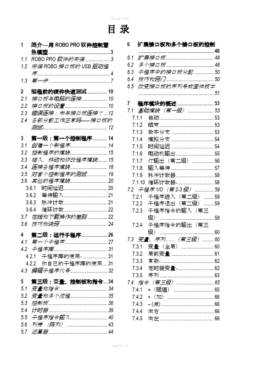
目录
1 简介----用 ROBO PRO 软件控制慧 鱼模型 ................................................. 3
1.1 ROBO PRO 软件的安装 .................... 3 1.2 安装 ROBO 接口板的 USB 驱动程
6 扩展接口板和多个接口板的控制 ............................... 48
6.1 扩展接口板 ...................................... 48 6.2 多个接口板 ...................................... 48 6.3 子程序中的接口板分配 ................ 50 6.4 技巧和窍门 ...................................... 50 6.5 改变接口板的序列号或固件版本
PyroSimExamples翻译版-

Figure 2.11. Evacuation modeling results 9
第3章。燃烧器火 在这一课中,你将创建一个500千瓦燃烧器火和测量温度的羽毛高1.5米。 这篇教程演示了如何。 创建一个燃烧器火•。 •加热电偶。 飞机加一片•温可视化。 运用3D结果Smokeview•观。 结果利用PyroSim•视图二维。
义为在创建或删除一个模拟障碍物。
当创建一个模型,对障碍物的几何不需要匹配的解决方案使用的网格的几何形状。然而,FD 的
解决方案将团结所有的解决方案网的几何结构。在 FD 的分析,都面临着被转移到对应到最近的
网状细胞障碍物。因此,一些障碍物可能成为较厚的分析,另一些则可能是先得薄,对应于一
个单细胞的脸,这有可能引入一个模型不需要的空白。这些不明确之处,可避免使所有几何对
表
面
表面是用来定义你的 FD 的固体物体模型的性能和通风口。表面可以使用前面定义的混合物或层
材料。默认情况下,所有的固体物质和通风口的惰性,这是一个在初始温度固定温度。
一
开
始
之
前
梗
阻
障碍物的最根本的火灾模拟软体(FDS)[文件描述符- SMV 的官方网站]几何表示。障碍是由二
点在三维空间中定义的矩形固体。表面性质分配给每一个阻塞的脸。设备和控制逻辑可以被定
但是,如果记录是“跌”(即从模拟省略)的模拟结果将不再代表原来的意图问题的例子。
乙
醇
潘
火
该例子说明了一个 ethanol_pan.fds 乙醇泛火灾。该模型显示在图 2.1。一个典型的结果显示在 图 2.2 。 文 件 描 述 符 的 输 入 文 件 可 以 下 载 : /svn/trunk/FDS/trunk/Validation/VU_Ethanol_Pan_Fire/ FDS_Input_Files / VU_Ethanol_Pan_Fire.fds。
PyroSim入门教程 文档
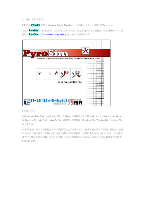
1. 运行一个FDS例子1.1 启动PyroSim(并打开Example Guide, Chapter 1)。
具体就不多说了,开始>程序>…………下面是PyroSim启动时的截图,上面有中文“火”的写法,但是看起来似乎是源自日文汉字(Kanji)的火。
但是开发PyroSim的Thunderhead engineering是一家位于美国的公司。
1.2 建立网格选择Model > Edit Grid ... 在跳出的面板上点New。
把网格的边界设置为Min X = 0,Max X = 10,Min Y = 0,Max Y = 10,Min Z = 0,Max Z = 10。
同时把网格数量设为X cells = 20,Y cells = 20,Z cells = 20。
如下图所示:在FDS里面,基本形状只能是长方体的(尽管通过长方体的组合,能模拟复杂的几何形状)。
网格也只能是正交网格(点确定后可以看到)。
这个例子是模拟风洞内的燃烧,风洞尺寸为10米*10米*10米。
每边划分成20个网格,总共有8000个网格。
在FDS中,由于求解器的特殊要求,每边划分的单元数通常要求是2,3或5的倍数。
点击OK后,网格就生成了,如下图所示:1.3 定义粒子这里的粒子并不是通常CFD软件里的拉格朗日粒子,只是为了后处理方便而定义的示踪粒子。
选择Model > Edit Particles ...,然后点New。
不要选Particle Have Mass,这样粒子没有质量,仅是示踪粒子。
选中Color Particles During Animation,使用默认的颜色,红色。
这样在结果中会有红色的示踪粒子。
1.4 建立面实际上,在建立网格的时候,我们已经得到了计算模型。
这里的面是用来定义边界条件。
要注意的是,这里仅仅定义边界条件,而没有给模型中的面指定边界条件。
也就是说只定义边界上的物理条件,但并没有和模型中的边界联系起来。
PyroSiM实例教程
PyroSim实用教程第1章安装教程安装PyroSim为了工作,通过本教程,您必须能够运行PyroSim。
您可以从互联网下载PyroSim,将可获得免费试用。
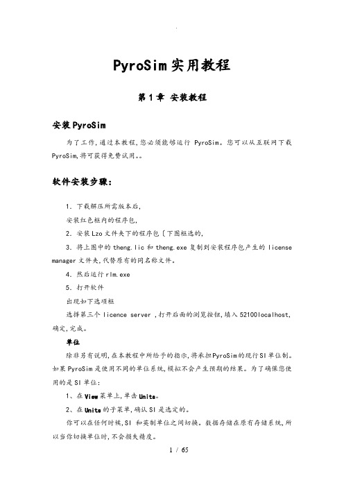
软件安装步骤:1.下载解压所需版本后,安装红色框内的程序包,2.安装Lzo文件夹下的程序包〔下图框选的,3.将上图中的theng.lic和theng.exe复制到安装程序包产生的license manager文件夹,代替原有的同名称文件。
4.然后运行rlm.exe5.打开软件出现如下选项框选择第三个licence server ,打开后面的浏览按钮,填入52100localhost,确定,完成。
单位除非另有说明,在本教程中所给予的指示,将承担PyroSim的现行SI单位制。
如果PyroSim是使用不同的单位系统,模拟不会产生预期的结果。
为了确保您使用的是SI单位:1、在View菜单上,单击Units。
2、在Units的子菜单,确认SI是选定的。
你可以在任何时候,SI和英制单位之间切换。
数据存储在原有存储系统,所以当你切换单位时,不会损失精度。
操作的三维图像•为了旋转〔spin三维模型:选择然后在模型上单击左键并移动鼠标。
该模型会旋转,就像您选择球体上的一个点。
•放大zoom:选择〔或按住ALT键和垂直拖动鼠标。
选择然后按一下拖动以定义一个缩放框。
•移动move模式:选择〔或按住Shift键并拖动来重新定位模型窗口。
•改变重点:选择对象〔S,然后选择定义一个较小的"查看选定对象周围的领域。
选择将重置,包括整个模型。
•在任何时候,选择〔或按Ctrl + R,将重置模型。
您还可以使用Smokeview和以人为本的控制。
请参阅用户手册为PyroSim 说明。
FDS的概念和术语材料用于定义材料热性能和热解行为。
表面表面是用来定义在您的FDS模型的固体物体和通风口的属性。
在混合物或层表面可以使用先前定义的材料。
默认情况下,所有的固体物体和通风口都是有惰性的,一个固定的温度,初始温度。
Pyramax中文入门版
Safety Labels 安全标签
Electrical
Crush
Crush
Pinch
Heat
Inhalation
EMO
Electrical under UPS
Safety Glasses
See Manual
Safety Gloves Lifting Point
Refractory Warning
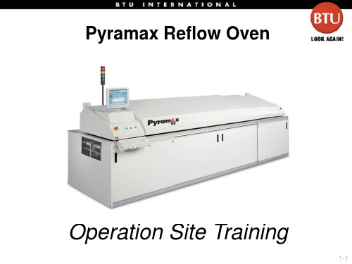
performingdailynormalshutdownfurnacerecipesetpoints设定massflowsetpointtableconfigured气体流量设定gassamplingsequencecontroltable气体采样顺序控制pressurezonesetpointtable静压设定conveyorfieldssetpointtable带速设定temperaturezonesetpointtable炉温设定setpointfolder参数设定页面静压设定气体采样顺序设定冷却吹风马达功率设定带速设定炉温设定recipeoptions功能选定basicatmospherecontrolsettings气氛开关auxiliaryequipmentonoffsettings设备功能开关temperatureoutputalarmaffectsprocessstate温度输出报警影响运行状态gassamplingdisableenable气体取样开关optionsfolderreadyindictordisableenableready开关pressureoutputalarmaffectsprocessstate静压输出报警影响运行状态producttrackingdisableenable产品跟踪开关屏蔽ready气体采样产品跟踪温度输出报警影响运行状态静压输出报警影响运行状态选项页面主控制加热传送带氮气recipealarmsatmospherecontrolalarmstabletemperaturepoweroutputalarmtablemassflowsetpointtableconfiguredpressurezoneoutputalarmstableconveyoroutputalarmstabletemperaturecontrolalarmstablealarmsfolderpressurepoweroutputalarmtablemassflowoutputalarmstableconfigured警报页面温度报警控制表气体报警控制表带速报警控制表静压报警控制表温度功率输出报警控制表压力功率输出报警控制表预警低限预警高限报警低限报警高限recipepidtrimpid功率temperaturepidtrimsettingstablepidtrimrecipewindo
远程SIM配置用户手册说明书

RemoteSIM Configurations User ManualMarch2023Introduction3 Requirements3 Scenario1:SIM Injector in LAN of Cellular Router4 Setup topology4 Configuring the SIM Injector/SIM Injector Mini4 Configuring the Cellular Router5 Scenario2:SIM Injector in WAN of main Router and multiple Cellular Routers8 Setup topology8 Additional configurations for Cellular Routers8 Configuration requirements for the main Router10 Scenario3:SIM Injector in LAN of main Router and multiple Cellular Routers11 Setup topology11 Main Router configuration12 Scenario4:SIM Injector in LAN of main Router and Dome with Starlink13 Setup topology13 Configuring the MAX HD2router14 Configuring the SIM Injector15 Configuring the HD1Dome Pro16 Scenario5:SIM Injector/SIM Injector Mini in a remote location18 Setup topology18 Cellular Router configuration18 How to check if a Peplink Cellular Router supports RemoteSIM20 Monitor the status of the RemoteSIM20 Appendix A:Declaration21IntroductionPeplink has developed a unique technology called RemoteSIM,which allows SIM cards to remotely link to a cellular router.This can be done via cloud or within the same physical network.There are a few key scenarios to fit certain applications.The purpose of this manual is to provide an introduction on where to start and how to set up for the most common scenarios and uses.Requirements-Cellular router that supports RemoteSIM technology.-SIM Injector.-SIM card.Notes:-Always check for the latest Firmware version for both the cellular router and the SIM Injector.You can also check for the latest Firmware version on the device’s WEBconfiguration page.-A list of products that support RemoteSIM can be found on the SIM Injector WEB page.Please check under the section Supported models.SIM Injector reset and login detailsHow to reset a SIM Injector:-Hold the reset button for5-10seconds.Once the LED status light turns RED,the reset button can be released.SIM Injector will reboot and start with the factory default settings. The default WEB login settings:-User:admin-Password:admin-IP address:the device only has a DHCP client and no fallback IP address..Therefore,it is advised to check every time what IP address is assigned to the SIM Injector.Notes:-The SIM Injector can be monitored via InControl2.Configuration is not supported.Scenario1:SIM Injector in LAN of Cellular RouterSetup topologyThis is the most basic scenario in which the SIM Injector/SIM Injector Mini(hereinafter referred to as SIM Injector)is connected directly to the cellular router’s LAN port via an ethernet cable. This allows for the cellular router to be positioned for the best possible signal.Meanwhile,the SIM cards can be conveniently located in other locations such as the office,passenger area,or the bridge of a ship.The SIM Injector allows for easily swapping SIM cards without needing to access a cellular router.IMPORTANT:Cellular WAN will not fallback to the local SIM if it is configured to use the SIM Injector.Configuring the SIM Injector/SIM Injector Mini1.Connect the SIM Injector to the LAN port of the cellular router.2.Insert SIM cards into the SIM Injector.The SIM cards will be automatically detected. IMPORTANT:SIM cards inserted into SIM Injector must not have a PIN code.Note1:The SIM Injector gets its IP address via DHCP and doesn't have a static IP address.To find it’s address,please check the DHCP lease on the cellular router.Configuring the Cellular RouterStep1.Enable the SIM Injector communication protocol.1a.If you are using a Balance cellular router,go to the Network tab(top navigation bar).1b.If you are using a MAX cellular router,go to the Advanced tab(top navigation bar).2.Under Misc.settings(left navigation bar)find Remote SIM Management.3.In Remote SIM Management,click on the edit icon next to Remote SIM is Disabled.4.Check the Auto LAN discovery checkbox and click Save and Apply Changes.5.Click Save and then Apply Changes.Step2.Enable RemoteSIM for the selected Cellular interface.1.Go to Network(top navigation bar),then WAN(left navigation bar)and click Details for a selected cellular WAN.This will open the WAN Connection Settings page.2.Scroll down to Cellular settings.3.In the SIM Card section,select Use Remote SIM Only.4.Enter configuration settings in the Remote SIM Settings section.Click on Scan nearby remote SIM server to show the serial number(s)of the connected SIM Injector(s).Available configuration options for cellular interface are shown below:A.Defining SIM Injector(s)-Format:<S/N>-Example1:1111-2222-3333-Example2:1111-2222-33334444-5555-6666B.Defining SIM Injector(s)SIM slot(s):-Format:<S/N:slot number>-Example1:1111-2222-3333:7,5(the Cellular Interface will use SIM in slot7,then5)-Example2:1111-2222-3333:1,21111-2222-3333:3,4(the cellular Interface will use SIM in slot1,then in2from the first SIM Injector,and then it will use3and4from the second SIM Injector).Note:It is recommended to use different SIM slots for each cellular interface.5.Click Save and Apply Changes.Step3.(Optional)Custom SIM cards settings.1a.For a Balance router,go to the Network(Top tab).1b.For a MAX router,go to the Advanced(Top tab).2.Under Misc.settings(Left-side tab)find Remote SIM Management.3.Click on the Add Remote SIM button,fill in all the required info and click Save.This section allows defining custom requirements for a SIM card located in a certain SIM slot: -Enable/Disable roaming(by default roaming is disabled).-Add Custom mobile operator settings(APN,user name,password).4.Repeat configuration for all SIM cards which need custom settings.5.Click Apply Changes to take effect.Scenario2:SIM Injector in WAN of main Router and multiple Cellular RoutersSetup topologyIn this scenario,each HD Dome creates a WAN connection to the main router.A single SIM Injector is used to provide SIM cards for each HD Dome.The HD Dome can be replaced with any Peplink cellular router supporting RemoteSIM technology.This scenario requires the completion of the configuration steps shown in Scenario1in addition to the configuration steps explained below.Additional configurations for Cellular RoutersStep1.Disable the DHCP server.-HD Dome1should act as a DHCP server.-HD Dome2should be configured to have a static IP address with DHCP disabled.-Both routers should be in the same subnet(e.g.192.168.50.1and192.168.50.2).1.Go to Network(Top tab),then Network Settings(Left-side tab),and click on Untagged LAN.This will open up the LAN settings page.2.Change the IP address to192.168.50.2.3.In the DHCP Server section,uncheck the checkbox to disable DHCP Server.4.Click Save and Apply Changes.Step2.Ethernet port configurationThe Ethernet port must be set to ACCESS mode for each HD Dome.To do this,dummy VLANs need to be created first.1.Go to Network(Top tab),then Network Settings(Left-side tab),and click on New LAN.This will open the settings page to create a dummy VLAN.2.The image below shows the values that need to be changed to create a new VLAN:Note:set different IP addresses for each HD dome(e.g.192.168.10.1and192.168.10.2).3.Click Save and Apply Changes.4.Go to Network(Top tab),then Port Settings(Left-side tab).5.Set the Port Type to Access and set VLAN to Untagged LAN(see picture below).6.Click Save and Apply Changes.Configuration requirements for the main RouterRequirements for the main router are:-Configure WAN1as a DHCP client.-WAN1will automatically get the Gateway IP address from HD Dome1.-Configure WAN2as a Static IP and set it to192.168.50.12.-Configure WAN2Gateway to192.168.50.2.Same as the HD Dome2’s IP address.Scenario3:SIM Injector in LAN of main Router and multiple Cellular RoutersSetup topologyIn this scenario,SIMs are provided to the HD Domes via the main router.In this example,the Remote SIM Proxy functionality needs to be enabled on the main router.Notes:-HD Dome can be replaced with any other cellular router that supports RemoteSIM.-It is recommended to use Peplink Balance series or X series routers as the main router.This scenario requires the completion of the configuration steps for the cellular router and the SIM Injector as in Scenario1.The configuration for the main router is explained below.Main Router configurationIMPORTANT:Main router LAN side and Cellular Routers must be configured using different subnets,e.g.192.168.50.1/24and192.168.100.1/24.Note:please make sure the Peplink router is running Firmware8.1.0or above.1.Open the main router WEB interface and change:From<IP address>/cgi-bin/MANGA/index.cgi to<IP address>/cgi-bin/MANGA/support.cgi.This will open the support.cgi page.2.Scroll down to find Remote SIM Proxy and click on[click to configure]that is located next to it.3.Check the Enable checkbox.4.Click on Save.5.Go back to the index.cgi page and click on Apply Changes.Scenario4:SIM Injector in LAN of main Router and Dome with StarlinkSetup topologyEquipment used:-HD1Dome Pro(MAX-HD1-DOM-PRO-5GD),FW version8.2.1-MAX HD2(MAX-HD2-LTEA-W-T),FW version8.2.1-SIM Injector Mini(SIM-MINI-8-1E),FW version1.1.120Configuring the MAX HD2routerIMPORTANT:Main router LAN side and Cellular Routers must be configured using different subnets,e.g.192.168.50.1/24and192.168.100.1/24.Step1.Change router subnet to192.168.100.1/24.1.Go to Network tab,then click on LAN network2.Change IP addresses to the new subnet:3.Click on Save.4.Go back to the index.cgi page and click on Apply Changes.Step2.Enable the Remote SIM Proxy1.Open the main router WEB interface and change:From192.168.100.1/cgi-bin/MANGA/index.cgi to192.168.100.1/cgi-bin/MANGA/support.cgi 2.Scroll down to find Remote SIM Proxy and click on[click to configure]that is located next to it.3.Check the Enable checkbox.4.Click on Save.5.Go back to the index.cgi page and click on Apply Changes.Configuring the SIM InjectorThere is no need to configure a SIM Injector mini.Once the HD2router configuration is finished you power on SIM Injector mini.IMPORTANT:in case SIM Injector Mini was connected to HD2before its configuration,then need to power off and then power on SIM Injector Mini.Configuring the HD1Dome ProStep1.Enable the SIM Injector communication protocol.1.By default the HD1Dome Pro IP address is192.168.50.1.Open WEB based configuration interface and then go to Advanced tab(top navigation bar).2.Under Misc.settings(left navigation bar)find Remote SIM Management.3.In Remote SIM Management,click on the edit icon next to Remote SIM is Disabled.4.Check the Auto LAN discovery checkbox and click Save and Apply Changes.5.Click Save and then Apply Changes and reboot the HD1Dome Pro.Step2.Enable RemoteSIM for the selected Cellular interface.1.Go to Network(top navigation bar),then WAN(left navigation bar)and click Details for a selected cellular WAN.This will open the WAN Connection Settings page.2.Scroll down to Cellular settings.3.In the SIM Card section,select Use Remote SIM Only.4.Click Scan nearby remote SIM server.The system must find the SIM Injector Mini serial number as shown below.5.Click Update RemoteSIM Settings.6.Click Save and Apply Changes.Step3.(Optional)Custom SIM cards settings.1.For a MAX router,go to the Advanced(Top tab).2.Under Misc.settings(Left-side tab)find Remote SIM Management.3.Click on the Add Remote SIM button,fill in all the required info and click Save.This section allows defining custom requirements for a SIM card located in a certain SIM slot: -Enable/Disable roaming(by default roaming is disabled).-Add Custom mobile operator settings(APN,user name,password).4.Repeat configuration for all SIM cards which need custom settings.5.Click Apply Changes to take effect.Scenario5:SIM Injector/SIM Injector Mini in a remote locationSetup topologyRequirements for installing a SIM Injector/SIM Injector Mini(hereinafter referred to as SIM Injector)in a remote location:●Cellular router communicates with the SIM Injector via UDP port50000.Therefore thisport must be reachable via public IP over the Internet.●The one way latency between the cellular router and the SIM Injector should be up to250ms.A higher latency may lead to instability issues.●The cellular router must have Internet connection to connect to the SIM Injector.It canbe another Internet connection via Ethernet or Fiber if possible,or a secondary cellular interface with a local SIM(Ignite SIM).●Due to its high latency,it is not recommended to use satellite WAN for connecting to aSIM Injector in remote locations.SIM Injector configuration is the same as in Scenario1.Cellular Router configurationStep1.Enable the SIM Injector communication protocol.1a.For a Balance cellular router,go to the Network(Top tab).1b.For a MAX cellular router,go to the Advanced(Top tab).2.Under Misc.settings(Left-side tab),find Remote SIM Management.3.In Remote SIM Management,click on the edit icon next to Remote SIM is Disabled.4.Enter the public IP of the SIM Injector and click Save and Apply Changes.Notes:-Do NOT check Auto LAN Discovery.-Adding a SIM Injector serial number to the Remote SIM Host field is a mistake! Step2.RemoteSIM and custom SIM card settings configurations are the same as in Scenario1.How to check if a Peplink Cellular Router supports RemoteSIM1.Go to Network(Top tab),then WAN(Left-side tab),and click Details on any cellular WAN. This will open the WAN Connection Settings page.2.Scroll down to Cellular settings.If you can see the Remote SIM Settings section,then the cellular router supports RemoteSIM.Monitor the status of the RemoteSIM1.Go to Network(Top tab),then WAN(Left-side tab),and click Details on the cellular WAN which was configured to use RemoteSIM.2.Check the WAN Connection Status section.Within the cell WAN details,there is a section for Remote SIM(SIM card IMSI,SIM Injector serial number and SIM slot).Appendix A:DeclarationFCC Requirements for Operation in the United StatesFederal Communications Commission(FCC)Compliance Notice:For SIM InjectorFederal Communication Commission Interference StatementAny changes or modifications not expressly approved by the party responsible for compliance could void your authority to operate the equipment.This equipment has been tested and found to comply with the limits for a Class B digital device, pursuant to part15of the FCC Rules.These limits are designed to provide reasonable protection against harmful interference in a residential installation.This equipment generates, uses and can radiate radio frequency energy and,if not installed and used in accordance with the instructions,may cause harmful interference to radio communications.However,there is no guarantee that interference will not occur in a particular installation.If this equipment does cause harmful interference to radio or television reception,which can be determined by turning the equipment off and on,the user is encouraged to try to correct the interference by one or more of the following measures:—Reorient or relocate the receiving antenna.—Increase the separation between the equipment and receiver.—Connect the equipment into an outlet on a circuit different from that to which the receiver is connected.—Consult the dealer or an experienced radio/TV technician for help.This device complies with Part15of the FCC Rules.Operation is subject to the following two conditions:(1)this device may not cause harmful interference and(2)this device must accept any interference received,including interference that may cause undesired operation.Industry Canada StatementThis product meets the applicable Innovation,Science and Economic Development Canada technical specifications.Le présent produit est conforme aux spécifications techniques applicables d'Innovation, Sciences et Développementéconomique Canada.This device contains licence-exempt transmitter(s)/receiver(s)that comply with Innovation, Science and Economic Development Canada’s licence-exempt RSS(s).Operation is subject to the following two conditions:(1)This device may not cause interference.(2)This device must accept any interference,including interference that may cause undesired operation of the device.Le present appareil est conforme aux CNR d'Industrie Canada applicables aux appareils radio ex-empts de licence.L'exploitation est autorisee aux deux conditions suivantes:(1)l’appareil ne doit pas produire de brouillage,et(2)l’utilisateur de l’appareil doit accepter tout brouillage radioelectrique subi,meme si le brouillage est susceptible d’enFCC Requirements for Operation in the United StatesFederal Communications Commission(FCC)Compliance Notice:For SIM Injector MiniFederal Communication Commission Interference StatementAny changes or modifications not expressly approved by the party responsible for compliance could void your authority to operate the equipment.This equipment has been tested and found to comply with the limits for a Class B digital device, pursuant to part15of the FCC Rules.These limits are designed to provide reasonable protection against harmful interference when the equipment is operated in a commercial environment.This equipment generates,uses,and can radiate radio frequency energy and,if not installed and used in accordance with the instruction manual,it may cause harmful interference to radio communications.Operation of this equipment in a residential area is likely to cause harmful interference,in which case the user will be required to correct the interference at his own expense.This device complies with Part15of the FCC Rules.Operation is subject to the following two conditions:(1)this device may not cause harmful interference and(2)this device must accept any interference received,including interference that may cause undesired operation.Industry Canada StatementThis product meets the applicable Innovation,Science and Economic Development Canada technical specifications.Le présent produit est conforme aux spécifications techniques applicables d'Innovation, Sciences et Développementéconomique Canada.This device contains licence-exempt transmitter(s)/receiver(s)that comply with Innovation, Science and Economic Development Canada’s licence-exempt RSS(s).Operation is subject to the following two conditions:(1)This device may not cause interference.(2)This device must accept any interference,including interference that may cause undesired operation of the device.Le present appareil est conforme aux CNR d'Industrie Canada applicables aux appareils radio ex-empts de licence.L'exploitation est autorisee aux deux conditions suivantes:(1)l’appareil ne doit pas produire de brouillage,et(2)l’utilisateur de l’appareil doit accepter tout brouillage radioelectrique subi,meme si le brouillage est susceptible d’enCE Statement for Pepwave Routers(SIM Injector Mini)contact as:https:///UK Statement for Pepwave Routers(SIM Injector Mini)。
Pyrosim软件介绍

Pyrosim软件介绍
FDS5_RCB_Source_Archive.zip 在百度搜这个据说能下载FDS 看着像挂马网站没敢试。
不过我感觉pysosim就是FDS
Pyrosim软件介绍
PyroSim是由美国标准技术研究院(NIST)研发的,专用于消防动态仿真模拟(Fire Dynamic Simulation, FDS)的软件。
它是在FDS 的基础上发展起来的。
软件以计算流体动力学为依据,可以模拟预测火灾中的烟气,CO等毒气的运动,温度以及浓度等情况;软件可以模拟的火灾范围很广,从日常炉火,房间,接电设备引起的各种火灾形式;方便快捷的建模,并支持DXF和FDS 格式的模型文件的导入。
PyroSim最大的特点是提供了三维图形化前处理功能,可视化编辑的效果,能够边编辑边查看所建模型,把用户从以前FDS 建模的枯燥复杂的命令行中解放了出来。
在PyroSim里面不仅包括建模、边界条件设置、火源设置、燃烧材料设置和帮助等,还包括FDS/ smokeview 的调用以及计算结果后处理,用户可以直接在PyroSim中运行所建模型。
功能组成:
模型设置模块--分析网格,几何物体,形状、尺寸,各部分材料、质地等;
表面设置模块--表面特性绝缘、惰性,供排气,加热或冷却炉;
化学反应设置模块--化学组成,燃点、燃烧热值等;
设备设置模块--一些烟气和温度探测,喷淋等方面的设备的设置;
运行模拟模块--运行,并输出数据、图表、动画等;
PyroSim支持导入二维和三维的CAD 的DXF文件,在二维CAD 平面图的基础上,您可以精确绘制建筑模型,也可以通过平面拉伸来形成墙体;。
pyrosim说明书翻译

6.4.1 停止和再启动一个重要的MISC 参数叫RESTART。
建立一个CHID.STOP 的文件在目录下。
重新开始,RESTART=.TRUE.需要添加到MISC行中。
第二章:PyroSim基础PyroSim界面pyrosim为您建立火灾模型提供了四个编辑器:3D模式,2D模式,导航模式和记录模式。
这些都可以显示您现在的模型。
当添加了、移除了、或在一个模式中选择了一个物体,其它的模式也同时反映出这些变化。
下面简要介绍这几种模式。
导航视图:在这个视图下列出了模型中许多重要的记录。
它可以使您将您的模型中几何体组成一个组,例如组成房间或者沙发。
在这个模式下,定位和修改档案比较快捷。
3D视图:这个视图中以3D形式显示了您的火灾模型。
您可以以不同的视角查看您的模型。
您也可以控制模型的外观细节,如平滑阴影、纹理和物体轮廓线,也可以改变几何特征。
2D视图:在这个视图中您可以快速的画出几何体,例如墙和家具。
您可以从三个视角查看您的模型,也可以执行许多有用的几何操作。
档案视图:这个模式给出了为本次模拟产生的FDS输入文件的预览。
它提供了加入不经过pyrosim处理而直接输入FDS的自己的代码的方式。
导航视图导航视图是在Pyrosim主窗口左部的树状视图。
下图是使用这个视图的一个例子。
当你右键点击这个视图中的一个项目时,将显示Pyrosim可以在这个项目上执行的功能。
重新排列物体时,点选一个物体,然后拖转至新的位置。
在导航视图中使用菜单3D视图运用3D视图可以迅速得到模型的视觉外观。
导航选项包括标准CAD控制模式,Smokeview型的控制,游戏型的控制查看模型。
3D轨道导航点击激活3D轨道导航。
这个模式的控制方式与许多CAD程序的控制模式相似。
旋转3D模型:点击后,左键点击模型并移动鼠标,模型将会随着您点选的点选转。
点选(或按住ALT键)并竖向移动鼠标。
选择后点击并拖动来定义缩放范围。
点选(或按住SHIFt键)并拖动,可以移动模型在窗口中的位置。
PyroSiM中文版用户说明书

第1章安装准备安装PyroSim为了工作,通过本教程,您必须能够运行PyroSim。
您可以从互联网下载PyroSim,将可获得免费试用。
单位除非另有说明,在本教程中所给予的指示,将承担PyroSim的现行SI单位制。
如果PyroSim是使用不同的单位系统,模拟不会产生预期的结果。
为了确保您使用的是SI单位:1、在View菜单上,单击Units。
2、在Units的子菜单,确认SI是选定的。
你可以在任何时候,SI和英制单位之间切换。
数据存储在原有存储系统,所以当你切换单位时,不会损失精度。
操作的三维图像为了旋转(spin)三维模型:选择然后在模型上单击左键并移动鼠标。
该模型会旋转,就像您选择球体上的一个点。
放大zoom:选择(或按住ALT键)和垂直拖动鼠标。
选择然后按一下拖动以定义一个缩放框。
移动move模式:选择(或按住Shift键)并拖动来重新定位模型窗口。
改变重点:选择对象(S),然后选择定义一个较小的“查看选定对象周围的领域。
选择将重置,包括整个模型。
在任何时候,选择(或按Ctrl + R),将重置模型。
您还可以使用Smokeview和以人为本的控制。
请参阅用户手册为PyroSim说明。
FDS的概念和术语材料用于定义材料热性能和热解行为。
表面表面是用来定义在您的FDS模型的固体物体和通风口的属性。
在混合物或层表面可以使用先前定义的材料。
默认情况下,所有的固体物体和通风口都是有惰性的,一个固定的温度,初始温度。
障碍物障碍物的根本在火灾动力学模拟的几何表示(FDS)[FDS- SMV的官方网站]。
障碍物两点定义在三维的矩形固体空间。
表面特性,被分配到每个面对的阻挠。
设备和控制逻辑可以定义创建或删除在模拟过程中的一个障碍。
当创建一个模型,障碍物的几何形状并不需要相匹配的几何网格的解决方案中使用。
然而,产品安全的解决方案将配合所有几何解决方案网状。
在FDS分析,阻塞所有的面转移到对应最近的网状细胞。
建筑火灾仿真工程软件:PyroSim从入门到精通

谢谢观看
第12章精通模型实 例——建模详解
作者介绍
同名作者介绍
这是《建筑火灾仿真工程软件:PyroSim从入门到精通》的读书笔记模板,暂无该书作者的介绍。
读书笔记
读书笔记
这是《建筑火灾仿真工程软件:PyroSim从入门到精通》的读书笔记模板,可以替换为自己的心得。
精彩摘录
精彩摘录
这是《建筑火灾仿真工程软件:PyroSim从入门到精通》的读书笔记模板,可以替换为自己的精彩内容摘录。
建筑火灾仿真工程软件: PyroSim从入门到精通
读书笔记模板
01 思维导图
03 目录分析 05 读书笔记
目录
02 内容摘要 04 作者介绍 06 精彩摘录
思维导图
本书关键字分析思维导图
软件
仿真
结构
软件
后处理
读者
模拟
仿真
应用
实例 第章
几何
建筑
基础
基本操作
实例
控件
模型对象内容摘要来自内容摘要本书结合作者多年的教学和培训实践,以PyroSim的流行版本——6.0版本为基础,全面系统地介绍了 PyroSim的使用以及工程应用实例。书中配合各小节实战练习及各阶段仿真模型实例详解,在实例应用中帮助读 者不断巩固所学软件知识,将软件学习与实际应用紧密结合,力求帮助读者快速入门并全面精通,最终熟练运用 PyroSim模拟仿真软件解决实际问题。本书可作为高等院校安全工程、消防工程、建筑工程专业本科、研究生的 教材,也可供广大安防科技工作者使用。
目录分析
第1章 PyroSim基础
第2章 PyroSim基本 操作
第3章 PyroSim模拟 仿真操作控件
第4章运行求解
prosim3使用说明书

责任和限制
本文档所含的信息会随时更改,且不代表 Fluke Biomedical 的承诺。对本文档信息的更改将并入新版本的出版物中。对于不是由 Fluke Biomedical 或其附属经 销商提供的软件,Fluke Biomedical 对其使用或可靠性不承担任何责任。
制造地点
ProSim™ 2/3 Vital Signs Simulator生产地址为:Fluke Biomedical, 6920 Seaway Blvd., Everett, WA, U.S.A。
ProSim™ 2/3
Vital Signs Simulator
用户手册
FBC 0038 January 2013, Rev. 1 (Simplified Chinese)
© 2013 Fluke Corporation. All rights reserved. Specifications are subject to change without notice. All product names are trademarks of their respective companies.
通告
保留所有权利
2013 Fluke Biomedical 版权所有。未经 Fluke Biomedical 书面同意,不得对本出版物的任何部分进行复制、传播、转录、存于可检索系统中,或译成任何其 它语言。
版权让渡
Fluke Biomedical 同意提供有限的版权让渡,以便您复制手册和其它印刷材料,用于服务培训课程和其它技术出版物的目的。如果您需要复制或分发其它材 料,请向 Fluke Biomedical 提交书面申请。
索赔
我们通常委托公共承运人负责运输,交货条款为产地离岸价。在交付时,若发现物理性损坏,请将所有包装材料保留原状并立即联系承运人,以便提交索 赔。如果仪器交付时物理状态良好,但不能在规格内工作,或者存在任何其它不是由运输损坏引起的问题,请与 Fluke Biomedical 或当地的销售代表联系。
- 1、下载文档前请自行甄别文档内容的完整性,平台不提供额外的编辑、内容补充、找答案等附加服务。
- 2、"仅部分预览"的文档,不可在线预览部分如存在完整性等问题,可反馈申请退款(可完整预览的文档不适用该条件!)。
- 3、如文档侵犯您的权益,请联系客服反馈,我们会尽快为您处理(人工客服工作时间:9:00-18:30)。
第1章安装准备安装PyroSim为了工作,通过本教程,您必须能够运行PyroSim。
您可以从互联网下载PyroSim,将可获得免费试用。
单位除非另有说明,在本教程中所给予的指示,将承担PyroSim的现行SI单位制。
如果PyroSim是使用不同的单位系统,模拟不会产生预期的结果。
为了确保您使用的是SI单位:1、在View菜单上,单击Units。
2、在Units的子菜单,确认SI是选定的。
你可以在任何时候,SI和英制单位之间切换。
数据存储在原有存储系统,所以当你切换单位时,不会损失精度。
操作的三维图像为了旋转(spin)三维模型:选择然后在模型上单击左键并移动鼠标。
该模型会旋转,就像您选择球体上的一个点。
放大zoom:选择(或按住ALT键)和垂直拖动鼠标。
选择然后按一下拖动以定义一个缩放框。
移动move模式:选择(或按住Shift键)并拖动来重新定位模型窗口。
改变重点:选择对象(S),然后选择定义一个较小的“查看选定对象周围的领域。
选择将重置,包括整个模型。
在任何时候,选择(或按Ctrl + R),将重置模型。
您还可以使用Smokeview和以人为本的控制。
请参阅用户手册为PyroSim说明。
FDS的概念和术语材料用于定义材料热性能和热解行为。
表面表面是用来定义在您的FDS模型的固体物体和通风口的属性。
在混合物或层表面可以使用先前定义的材料。
默认情况下,所有的固体物体和通风口都是有惰性的,一个固定的温度,初始温度。
障碍物障碍物的根本在火灾动力学模拟的几何表示(FDS)[FDS- SMV的官方网站]。
障碍物两点定义在三维的矩形固体空间。
表面特性,被分配到每个面对的阻挠。
设备和控制逻辑可以定义创建或删除在模拟过程中的一个障碍。
当创建一个模型,障碍物的几何形状并不需要相匹配的几何网格的解决方案中使用。
然而,产品安全的解决方案将配合所有几何解决方案网状。
在FDS分析,阻塞所有的面转移到对应最近的网状细胞。
因此,一些障碍物有可能成为在分析厚;其他可能成为薄,对应于一个单细胞的脸,这有可能引入不必要的到模型的差距。
这些含糊之处,可避免使所有的几何对应网格间距。
通风口有一般使用上的通风口FDS集团来描述二维平面物体。
从字面上理解,一个用于排气模型组件通风系统的建筑,如扩散或回报。
在这些情况下,排气坐标定义为一个平面形成的边界风管。
你也可以使用通风口作为一种手段,应用到某一特定边界条件下的矩形表面。
例如一堆火,可由指定一个排气口或者网边界或固体表面上产生。
通风口表面定义了火所需要特性的。
计算网格在FDS集团直线域内进行的计算称为网格。
每个网格划分为矩形。
当进行选择时必须考虑这两个因素。
矩形尺寸达到了所需要的分辨率定义对象模型(障碍)和理想的流量动力学分辨率解决方案(包括当地消防诱导的影响)的要求。
虽然几何对象(障碍)在一个FDS场模拟分析中可以指定试样尺寸不落在矩形所处的坐标,但在FDS解决方案中,所有的阻力都转向了最近的矩形。
如果一个阻塞是非常小,两个面可以近似为相同的矩形。
FDS用户指南[McGrattan,克莱恩,Hostikka、弗洛伊德、2009]建议,全功能、障碍物应指定至少一层矩形的厚度。
作为一个结果,矩形大小必须足够小,但能够合理地代表问题的几何形状。
另外,矩形块应该尽可能接近立方体。
矩形尺寸是否足以解决水流动力条件方案只能由网格敏感性研究确定。
关于网格大小的模型敏感性将在章节5验证,对于核能电厂的火灾模型选择的的应用[美国:2007)。
它的职责是进行灵敏度分析,以研究作为部分任何仿真。
第二章Example Problems Provided with FDS 5如果你想要觉得有趣并能很快的进行一些实例分析,你可以导入包含了NIST的FDS5输入文件。
在PyroSim2009\SAMPLES\FDS5文件夹的PyroSim分布中提供了这些例子。
本章我们列举几个例子,当然你可以导入更多。
研究这些例子大大有利于了解不同类型的分析输入。
为了打开这些例子,你需要:1、获得所需的FDS5输入文件。
2。
打开PyroSim。
3。
在File中单击Import并选择FDS文件。
4。
在Open File对话框中,单击FDS输入文件。
PyroSim将导入该文件。
如果不能导入FDS文件中的任何记录,PyroSim会发出警告。
5。
在File栏,单击Save,把它保存在一个新的目录中。
6。
在FDS菜单中,单击Run FDS将会启动分析。
分析结束后,SmokeView会开始查看结果。
重要事项:如果PyroSim不完全支持FDS输入文件,它会发出一个警告,其中包括关于如何处理陌生的记录信息。
在某些情况下,PyroSim能把记录添加到Additional Records 部分中并使模拟不受影响。
但如果记录是“下降”(即从模拟略),模拟结果将不再代表例子的原意。
乙醇潘火ethanol_pan.fds的例子说明了一个乙醇潘火。
该模型在图2.1中有所显示。
图2.2所示的是一个典型的结果。
FDS输入文件可以在以下网址下载:图2.1。
乙醇泛模型图2.2。
乙醇泛结果图2.3。
计算和测量的热释放速率的比较箱燃烧消失:box_burn_away.fds的例子说明了一个泡沫箱燃烧。
该模型如图2.4。
一个典型的结论如图2.5所示。
FDS输入文件可以在以下网址下载:图2.4。
泡沫箱燃烧距离模型图2.5。
泡沫箱烧掉结果绝缘钢柱insulated_steel_column.fds的例子说明了成列的热传导。
模型如图2.6所示。
一个典型的结论如图2.7所示。
FDS输入文件可以在下列网址中下载:Heat_Transfer/ insulated_steel_column.fds。
图2.6。
绝缘钢柱模型图2.7。
绝缘钢柱结果水冷water_cooling.fdsSprinklers_and_Sprays/ water_cooling.fds中下载。
图2.8。
水冷却模型图2.9。
水冷结果疏散PyroSim支持了FDS+ EV AC疏散模型的输入。
evac_example1a.fds EV AC的信息PROJ/ fdsevac/ index.jsp。
请注意,Thunderhead的工程在EV AC和探路者模型可以用来提供备用疏散建模的方法。
图2.10。
疏散建模示例图2.11。
疏散模拟结果第三章Burner Fire在这个教程中,你将会创造一个500瓦的燃烧火焰并将测量烟柱中心高度为1.5米的温度。
这篇教程展示了该如何操作:·创建一个燃烧火焰·添加一个热电偶·添加一个温度可视化扫描平面·运用Smokeview观点查看3D结果·运用PyroSim观点查看2D结果图3.1,在这一例子的燃烧火焰在你开始之前,确保你使用SI单位(见第一章)。
创建网格这个例子里,我们将用0.13米宽的网细胞。
对500千瓦火焰来说,这个值大约是1/5特征直径(D *)。
就想拇指规则一样,在一个烟柱模型中,这是一样大的能够在仍然保持一个中等水平的建模精度网状细胞,[美国描述:2007)。
使用小网格细胞因子2应该减少误差4倍,但会增加仿真运行时间通过一个因素的16。
1.在Model 菜单上,单击Edit Meshes.....2.点击New。
3.接受默认名称MESH。
点击OK。
4.在Min X空格输入-1.0,在Max X空格输入1.0。
5.在Min Y空格输入-1.0,在Max Y空格输入1.0。
6.在Min Z空格输入0.0,在Max Z空格输入3.0。
7.在X Cells空格输入15。
8.在Y Cells 空格输入15。
9.在Z Cells空格输入24。
10.点击OK保存更改并关闭对话框Edit Meshes。
图3.2。
创建网格创建燃烧器表面在FDS模型中表面是用于定义对象的性质。
在这个例子中,我们定义一个燃烧器表面,释放热量速率为500千瓦/平方米。
1.在Model菜单上,单击Edit Surfaces....2.点击New....3.在Surface Name空格中输入burner,见图3.3。
4.在Surface Type菜单中,选择Burner。
5.点击OK,创造出新的默认燃烧器的表面。
图3.3。
创造一个新的燃烧器的表面1.在Description空格,输入500 kW/m2 burner,见图3.4。
2.点击OK保存更改并关闭Edit Surfaces对话框。
图3.4。
定义参数为燃烧器的表面创造燃烧器通风口在这个例子中,我们使用一个通风口以及为了规定火焰预先建立起燃烧器表面。
(回忆在FDS中,一个“通风口”可以成为一个2 D表面用于应用边界条件对一个矩形补丁。
) 1.Model上的菜单,点击New Vent....2.在Description空格输入burner vent,见图3.5。
3.在Surface菜单,选择burner。
这说明先前创造了燃烧器的表面将定义通风口的性质。
4.点击Geometry标签。
在Plane菜单,选择Z。
5.在Min X空格输入-0.5,在Max X空格输入0.5。
6.在Min Y空格输入-0.5,在Max Y空格输入0.5。
7.点击OK,创造出新的燃烧器通风口。
图3.5。
创造燃烧器通风口创造顶部通风口1.Model上的菜单,点击New Vent....2.在Description空格输入open top。
3.在Surface的列表中,选择OPEN。
这是一个默认的表面,这意味着这将成为一个开放的边界。
4.点击Geometry标签。
在Plane列表中,选择Z输入3.0。
5.在Min X空格输入-1.0,在Max X空格输入1.0。
6.在Min Y空格输入-1.0,在Max Y空格输入1.0。
7.点击OK创造开放的通风口。
添加一个热电偶1.在Devices菜单上,单击New Thermocouple....2.在Device Name空格输入thermocouple at 1.5 m。
3.位置Location行上,在Z框中,键入1.5。
4.单击OK以创建热电偶。
一个黄点会出现在模型中心。
点击Show Labels,切换和关闭标签。
添加温度切片平面1在Output菜单上,单击Slices....2.在XYZ Plane,单击该单元格,选择Y。
3.在Plane Value列中,单击该单元格类型0.0。
4.在Gas Phase Quantity,单击该单元格,选择Temperature。
5.在使用Use Vector?,单击该单元格,选择NO。
6.单击OK以创建切片平面。
单击Show Slices,来控制切换切片机开启和关闭。
为更好地查看而旋转模型1.要重置变焦和正确选择中心,按Ctrl + R .PyroSim现在将向下俯视沿Z轴的模型。
