CFAST使用指南
功能单元最大行数

文档名称:功能单元最大有效行数作者:日期:1 分析功能单元这里指的是函数,即整个项目中所有.c文件的函数的最大有效行数,针对找到的开源工具,有个可以利用:C and C++ Code Counter和makeheaders,其中C and C++ Code Counter在《功能单元最大扇入扇出工具分析》中已经介绍,其中有这样的功能,即列出所有函数的LOC。
Makeheaders 能够把.c文件中的全局变量和函数定义抽取出来,自动生成头文件。
因此一种思路是根据makeheaders和C and C++ Code Counter的代码抽取出来,在此基础上进行字符串的匹配,这种思路虽然可以实现,但是不如解析c 的语法来实现可靠。
第二种方法即是基于c的语法分析来实现。
本文的主要目的就是介绍搜集到的常用的c的解析器。
2 cscope2.1 简介度量工具名称cscope网址/操作方式命令行实现语言C++适用的操作系统Linux可以度量的属性LOC MVC COM LOC/COM MVG/COMFan-out Fan-in HKS NOM WMC REJ备注开源,有源代码,可分析后在基础上修改Cscope的功能通过它的子命令“find”来实现。
cs find c|d|e|g|f|i|s|t name∙s:查找C代码符号∙g:查找本定义∙d:查找本函数调用的函数∙c:查找调用本函数的函数∙t:查找本字符串∙e:查找本egrep模式∙f:查找本文件∙i:查找包含本文件的文件2.2工具优缺点总结Cscope是AT&T官方发布的Unix的一部分,cscope 是一个C 语言的浏览工具,通过这个工具可以很方便地找到某个函数或变量的定义位置、被调用的位置等信息。
目前支持 C 和C++。
cscope 自身带一个基于文本的用户界面,不过gvim 提供了cscope接口,因此可以在gvim 中调用cscope,方便快捷地浏览源代码。
COMPASS 5000基本操作手册-PK
COMPASS 2000操作使用手册目录目录 (1)一.COMPASS概述 (7)1.COMPASS优点: (7)2.COMPASS主要具有三个主要的功能,同时还有一个功能强大的测绘工具。
(7)3.COMPASS系统还有如下功能: (8)4.COMPASS还拥有如下一些实用工具 (8)二.简要的操作指南 (9)1.To open a wellpath(打开井眼): (9)2.To view wellpath:(查看井眼) (9)3.Open another wellpath(打开其它井眼) (9)4.To Create a plan:(创建一个井的设计)[参看设计模块] (9)5.To edit a survey:(编辑测量) [参看测量模块] (9)6.To view a wellpath’s survey program:(查看井眼轨迹的测量组合) (10)7.Anticollision(防碰)[参看防碰模块] (10)四Compass数据结构 (10)4。
1 working at the Company level (10)4.2 working at the project level (31)4.3 Working at the site level (35)4。
4 Working at the Well Level (38)4.5 working at the Wellbore level (42)4.6 Working at Plan design level (42)4.7 concepts (44)五planning module (44)6.Template模板 (52)7.Targets 靶区 (64)五.Survey测量...................................................................................................................... 错误!未定义书签。
与摄影器材相关的英语单词
与摄影器材相关的英语单词Photography Equipment: A Comprehensive GuideIntroductionPhotography has become an integral part of our lives, capturing moments and preserving memories for eternity. To capture stunning shots, photographers rely on a vast array of equipment. In this comprehensive guide, we will explore the key photography equipment that every budding or professional photographer should know about.1. CamerasCameras are, undoubtedly, the most critical piece of photography equipment. There are various types of cameras available in the market, including DSLRs (Digital Single-lens Reflex), mirrorless cameras, and point-and-shoot cameras. DSLRs are preferred by professionals due to their versatility, image quality, and interchangeable lenses. Mirrorless cameras offer similar features in a more compact package, while point-and-shoot cameras are suitable for amateurs or casual photographers.2. LensesLenses play a crucial role in capturing stunning photographs. They determine the focal length, aperture, and perspective of the image.A wide-angle lens is useful for landscape or architectural photography, while a telephoto lens is ideal for capturing distant subjects. Portrait photographers prefer prime lenses, while zoomlenses provide flexibility. Additionally, macro lenses are used for detailed close-up shots, and fisheye lenses create unique distorted images.3. TripodsA tripod is an essential accessory for photographers, especially when shooting in low light conditions or for long exposures. It provides stability, reduces camera shake, and ensures sharp images. Tripods come in various sizes and materials, including aluminum, carbon fiber, and lightweight travel-friendly options.4. FlashlightsFlashlights or external flashes are indispensable for photographers, enabling them to control and manipulate lighting conditions. They are beneficial in low light situations, creating a balanced exposure or adding fill light to eliminate shadows. Additionally, flashes can be used to bounce light off walls or ceilings for softer lighting.5. Memory CardsMemory cards are used to store photographs and videos captured by cameras. They come in various formats such as SD (Secure Digital), CFast (CompactFlash), and XQD cards. It is recommended to have multiple memory cards with ample storage capacity to avoid running out of space and ensure safe backups. 6. FiltersFilters are essential accessories that photographers can attach to their lenses to achieve specific effects or adjust the lighting conditions. Some common filters include UV filters (protective and reduce haze), polarizing filters (reduce reflections and enhance colors), and ND (Neutral Density) filters (reduce the amount of light entering the lens).7. Camera BagsCamera bags are designed to securely store cameras, lenses, and other accessories during transportation. They come in various sizes, shapes, and designs, such as backpacks, shoulder bags, and rolling cases. It is essential to choose a camera bag that suits your needs in terms of storage capacity, durability, and comfort.8. Cleaning KitsCleaning kits are essential for maintaining the cleanliness and functionality of photography equipment. They typically include a blower brush, lens cleaning solution, microfiber cloth, and sensor cleaning swabs. Regular cleaning ensures the longevity and optimum performance of cameras and lenses.ConclusionPhotography equipment constitutes a significant investment for photographers. Knowing the essential equipment and understanding their functions aids in capturing stunning and impactful images. This comprehensive guide provided an overview of the various photography equipment, including cameras, lenses,tripods, flashlights, memory cards, filters, camera bags, and cleaning kits. By having a good grasp of these tools, photographers can explore their creativity and capture memorable moments with finesse.综合指南:摄影器材介绍摄影已成为我们生活中不可或缺的一部分,记录下每一个美好瞬间,留存珍贵回忆。
Parasoft-CTest操作手册

C++Test介绍修订历史记录目录第一章C++Test 特性 (4)第二章C++Test 使用 (6)一.安装说明 (6)1.Windows下安装 (6)2.申请License (6)二.启动C++Test (7)1.从VC++里启动C++Test (7)2.传统启动C++Test (8)三.Linux下安装及启动 (9)四.C++Test快速测试 (10)1.打开被测文件 (10)2.静态测试 (12)3.动态测试 (14)4.生成报表 (16)第三章C++Test高级功能 (19)一.导入VC++工程(Import VC++ project) (19)二.选择编译器(project configuration) (20)三.设置测试配置(test configuration ) (21)四.编码规则测试结果分析 (26)五.测试用例分析 (28)六.Data Source (33)七.桩函数设置 (40)八.导入导出测试用例 (43)九.T est Objects (45)十.覆盖率分析 (48)十一.回归测试 (52)十二.其他设置 (55)1.设置TCM (55)2.设置GRS (56)3.设置源代码编辑器和HTML浏览器 (57)第四章RuleWizard定制规则 (59)一.启动RuleWizard (59)二.打开一个现有的规则 (60)三.设计一个新规则 (62)四.C++Test中导入自定义规则 (71)第一章C++Test 特性C++Test是一个C/C++单元测试工具,自动测试任何C/C++类、函数或部件,而不需要您编写一个测试用例、测试驱动程序或桩调用。
C++Test能够自动测试代码构造(白盒测试)、测试代码的功能性(黑盒测试)和维护代码的完整性(回归测试)。
C++Test是一个易于使用的产品,能够适应任何开发生命周期。
通过将C++Test集成到开发过程中,您能够有效地防止软件错误,提高代码的稳定性,并自动化单元测试技术(这是极端编程过程的基础)。
CASP系统使用手册
目录前言第一章CASP系统的安装、设置和升级一、CASP系统的安装二、CASP系统的设置三、CASP系统的升级第二章CASP系统的使用第一节配载计划程序(CASP主程序)的使用一、启动二、界面和操作说明1、菜单使用说明1)FILE菜单2)EDIT菜单3)PLAN菜单4)OPTION菜单5)TOOLS菜单6)STABILITY菜单(未做说明)7)PRINT菜单2、注意事项第二节EDI程序的使用一、各种格式的EDI报文1、国际通用格式:EDIFACT BAYPLAN "BAPLIE"1.52、交通部格式:船图(BAPLIE)平台文件-BAPLIE MOC3、中远格式:COSCO4、CASP系统的ASC文件二、CASP系统的EDI程序的界面说明1、OPTION菜单1)设置SENDER2)设置TRADING PARTNER3)设置PORT CODES和OPERATOR CODES4) Configuration2、FILE菜单3、Translate菜单三、EDI程序的报文转换操作说明1、Standard To CASP2、CASP To Standard第三节如何使用CONTAINER DATA EDITOR一、启动、打开ASC文件二、编辑ASC文件1、认识TOOL BAR(工具栏)2、熟悉主菜单1)FILE菜单2)EDIT菜单3)Tool菜单4)WINDOW和HELP菜单三、合成船图1、船图的基本合成2、合成船图时常出的错误、分析及解决办法1)没有任何倒箱动作,但在合成船图时出错2)发生倒箱动作后的船图合成四、注意事项CASP系统的用户手册前言CASP(Computer Automated Stowage Planning)系统全称为电脑自动化配载计划系统,由韩国TOTAL SOFT BANK LTD.生产。
此套软件主要功能是帮助配载员设计出最佳的配载计划(配载图),以其可靠的操作性能减少文书工作并提高船舶的安全。
消防安全人员疏散软件的比较
人员疏散软件的比较一、人员疏散软件-Simulex1Simulex软件简介Simulex的开发公司是由苏格兰集成环境解决有限公司(Integrated Environmental Solutions Ltd)的Peter Thompson博士开发,用来模拟大量人员在多层建筑物中的疏散。
年费1000英镑,永久使用2600英镑,采用C++语言编制。
只能模拟在紧急情况下人员的疏散活动,不能模拟在建筑物正常运作情况下的人流运动。
2软件应用能力2.1疏散能力可以模拟大型、复杂几何形状、带有多个楼层和楼梯的建筑物,可以容纳上千人,用户可以看到在疏散过程中,每个人在建筑物中的任意一点、任意时刻的移动。
仿真结束后,会生成一个包含疏散过程详细信息的文本文件。
2.2场景设置Simulex把一个多层建筑物定义为一系列二维楼层平面图,这些楼层平面通过楼梯相连接。
从每一个楼层进入楼梯的出口要在楼层平面窗口和楼梯窗口都指定。
楼梯和楼层片面由“link”连接,在模型中将其位置放在出口的位置。
模型中的人员可以通过连接从楼层进入楼梯,反之亦然。
Simulex无内置制图工具,楼层平面图必须来自于CAD软件包,例如AutoCAD,CADD,或者QuickCAD。
平面图必须用标准的二维DXF文件格式存储。
2.3人群设定Simulex用三个圆来代表每一个人的平面面积,精确地模拟了实际的人员。
每一个被模拟的人由一个位于中间的不完全的圆圈,和两个稍小的、与中间的圆重叠的肩膀圆圈所组成,它们排列在不完全的圆圈两侧。
如下图所示simulex人群设定2.4楼梯及连接定义Simulex假设一个楼梯可以用二维线性走廊代替,三维螺旋形楼梯也被简化成二维直线形式。
对于连接的定义,用户需要在楼层平面和楼梯之间定义特定宽度的连接,以构造一栋建筑物的三维形式。
无论何时,只要楼层平面和楼梯之间有开口就需要一个连接,每一个连接都有宽度和位置。
2.5出口定义最终出口直线代表了建筑物中人员的最终目标,当一个人到达最终出口,就认为已经逃生。
Moxa V2403系列无风扇x86嵌入式计算机用户操作指南说明书

P/N: 1802024030012 *1802024030012*V2403 SeriesQuick Installation GuideVersion 2.1, January 2021Technical Support Contact Information/support2021 Moxa Inc. All rights reserved.OverviewThe Moxa V2403 series fanless x86 embedded computer is based on the Intel® 3rd gen Core-i™ series processor, features the most reliable I/O design to maximize connectivity, and supports dual wireless modules, making it suitable for a diverse range of communication applications. The computer’s thermal design ensures reliable system operation in temperatures ranging from -40 to 70°C with a special purpose Moxa wireless module installed. The V2403 series supports “Moxa Hardware Monitoring” for device I/O status monitoring and alerts, system temperature monitoring and alerts, and system power management. Closely monitoring system status makes it easier to recover from errors and provides the most reliable platform for your applications. Package ChecklistBefore installing the V2403, verify that the package contains the following items:•V2403 embedded computer•Terminal block to power jack converter•Wall mounting kit•Quick installation guide (printed)•Warranty cardNOTE: Please notify your sales representative if any of the above items are missing or damaged.V2403 Panel LayoutThe following figures show the panel layouts of the V2403.Front ViewRear ViewLED IndicatorsThe following table describes the LED indicators located on the front panel of the V2403. LED Name LED Color LED FunctionPowerGreen Power is on and functioning normally. OffPower is off or power error exists.Storage YellowCFast card/HDD/SSD is transmitting data OffCFast card/HDD/SSD is not transmitting data LAN (1 or 2) Green100 Mbps Ethernet mode Yellow 1000 Mbps Ethernet mode Off10 Mbps or no activityTX (P1-P4) GreenSerial ports P1-P4 transmitting data OffSerial ports P1-P4 not transmitting data RX (P1-P4) YellowSerial ports P1-P4 receiving data OffSerial ports P1-P4 not receiving dataNOTE The mini-PCIe card’s LED behavior depends on the module.Installing the Mini-PCIe Modules and USIM CardsThe V2403 features 3 mini-PCIe sockets on the bottom panel. • Socket 1: USB + PCIe signal, for Wi-Fi mini-PCIe card• Socket 2: USB signal, for 3G/LTE mini-PCIe card (Sierra Wireless MC7304, MC7354, MC9090)•Socket 3: SATA signal (for mSATA)Installing a mini-PCIe Card in Socket 1 and Socket 3STEP 1: Loosen the 6 screwsin the middle of the bottomcover and then open thebottom cover.STEP 2: Obliquely insert the mini-PCIe module card.STEP 3: Push down the mini-PCIe module card and fasten it with the 2 black screws from the module card package you purchased from Moxa. STEP 4: If you installed a wireless mini-PCIe card, connect the antenna cables with wireless module card.No.1 & No.3: Wi-Fi mini-PCIe card.STEP 5: Replace the bottom cover.Installing a mini-PCIe Card in Socket 2STEP 1: Loosen the 6 screwsin the middle of the bottomcover and open the bottomcover.STEP 2: Get the upper heat sink cover fromthe wireless package.STEP 3: Obliquely insert the mini-PCIe module card in socket 2, and fasten it with the 2 black screws from the wireless package.STEP 4: Connect the antenna cables to the wireless module card:No. 2 & No. 4: 3G/LTE mini-PCIe card No. 5: GPSSTEP 5: Use the fillister to obliquely buckle the heat sink that was already installed inside the V2403 computer, as shown below:→STEP 6: Slightly push down the upper heat sink cover and use the silver screw from the wireless package to fasten the upper heat sink cover (outlined in red below).→STEP 7: Replace the bottom cover. Installing the USIM cardThe V2403 has 2 USIM slots for 3G/LTE wireless Internet connections. Instructions for installing a USIM card are shown below:Pull up the USIM card slot and insert the USIM card. When finished, replace the holder and slide the slot towards the catch to fasten the holder.→NOTE You may also purchase 3G, 4G, and Wi-Fi external antennas from from Moxa. Please contact Moxa sales representative for yourdemand.Installing the V2403DIN-Rail MountingThe V2403 can be installed on a DIN-rail withthe optional DIN-rail kit. The DIN-rail kitmust be purchased separately. The DIN-railkit includes two DIN-rail brackets and eightscrews.To attach the DIN-rail kit, complete the following steps:1.Turn the V2403 over so the bottom is facing up.2.Locate the screw holes on the bottom of the V2403.3.Place the brackets on the bottom of the V2403 and align the screwholes on the brackets with the screw holes on the V2403.4.Insert and tighten the screws into the screw holes.NOTE Use all eight screws to ensure that the V2403 is safely and securely installed on the DIN rail.5.When the brackets are firmly attached with the screws, you caninstall the V2403 onto a DIN-rail.To remove the V2403 from the DIN-rail, first use a screwdriver to pull down the DIN-rail connector to unlock it.To re-install the V2403 on the DIN-rail, use a screwdriver to press the buckle so that it can be released. At this point, it can be re-installed on the DIN-rail.Wall or Cabinet MountingThe V2403 comes with two metal brackets for attaching it to a wall or the inside of a cabinet.Step 1: Use two screws for each bracket and attach the bracket to the rear of the V2403.Step 2: Use four screws per side to attach the V2403 to a wall or cabinet.Connector DescriptionPower ConnectorConnect the 9 to 36 VDC LPS or Class 2 power line to the V2403’s terminal block. If the power is supplied properly, the Power LED will light up. The OS is ready when the Ready LED glows a solid green. Grounding the V2403Grounding and wire routing help limit the effects of noise due toelectromagnetic interference (EMI). Run the ground connection from the grounding screw (M4) to the grounding surface prior to connecting the power.DVI-I OutputsThe V2403 comes with 1 DVI-I female connector for the DVI display. This output interface is located on the front panel of the product. Be sure touse the correct cable to connect the computer to the display.HDMI OutputsThe V2403 comes with a type A HDMI female connector and a DVI-I female connector on the front panel to connect an HDMI or DVI-I supported monitor.The screw hole above the HDMI connector is used to attach a customized lock to the HDMI connector; a custom lock is needed since the shape of different HDMI connectors are not the same. Please contact a Moxa sales representative for details.The lock appears as shown below:The lock should appear as shown here after it is attached to the V2403:Ethernet PortsThe 10/100/1000 Mbps Ethernet ports use RJ45 connectors.Pin 10/100 Mbps 1000 Mbps1 ETx+ TRD(0)+2 ETx- TRD(0)-3 ERx+ TRD(1)+4 – TRD(2)+5 – TRD(2)-6 ERx- TRD(1)-7 – TRD(3)+8 – TRD(3)-Serial PortsThe serial ports use DB9 connectors. Each port can be configured by software for RS-232, RS-422, or RS-485. The pin assignments for the ports are shown in the following table:Pin RS-232 RS-422 RS-485(4-wire)RS-485(2-wire)1 DCDTxDA(-) TxDA(-) –2 RxD TxDB(+) TxDB(+) –3 TxD RxDB(+) RxDB(+) DataB(+)4 DTR RxDA(-) RxDA(-) DataA(-)5 GND GND GND GND6 DSR – – –7 RTS – – –8 CTS – – –SATA ConnectorThe V2403 has 1 SATA-I/II connector for 2.5” SSD/HDD storage expansion. To expand storage capacity, purchase an SSD/HDD and an internal storage kit* through Moxa’s CTO** service.* M ust be purchased separately for installing an SSD/HDD. For details, check the optional accessories section of the V2403 datasheet.** C TO = Configure to ordermSATA ConnectorThe V2403 has 1 mini-PCIe socket with SATA signal for storage expansion. Follow the “Installing the Wireless Modules” instructions.CFast SlotThe V2403 has 2 CFast sockets. One slot is located on the front panel for OS storage and the other slot is located inside the V2403 for backup OS storage. Both slots support CFast Type-I/II with DMA mode.To install an OS CFast card, remove the outer cover and insert the CFast card in the socket. When finished, push the cover into the socket and refasten the screws.To install a CFast card for backup storage, purchase a CFast card through Moxa’s CTO service. Refer to the V2406A datasheet for more information. USB HostsThe V2403 has 4 USB 2.0 Type A connectors. 2 USB ports are located on the front panel; the other 2 USB ports are located on the rear panel. The port supports keyboard and mouse, and can also be used to connect a FlashDisk for storing large amounts of data.Audio InterfaceThe V2403 comes with a Line-in audio connector for audio input and a Line-out audio connector for audio output, allowing users to connect a speaker or earphones.DI/DOThe V2403 comes with 4 digital inputs and 4 digital Array outputs on a 2x5 terminal block.Reset ButtonPress the “Reset Button” on the rear panel of the computer to reboot the system automatically. Pushing the reset button will restart system immediately. Be aware that all unsaved data will be lost when pushing this button.Real-time Clock (RTC)The V2403’s real-time clock is powered by a lithium battery. You can easily replace the battery yourself using an optional battery kit*. However, please note that there is a risk of explosion if the battery is replaced by an incorrect type of battery. Refer to the V2403 Hardware User's Manual or contact a qualified Moxa support engineer if you have any questions about the RTC battery.* M oxa offers an “RTC battery kit” that you can use to easily replace the battery. For details, check the optional accessories section of the V2403datasheet.Powering on the V2403To power on the V2403, connect the “terminal block to power jack converter” to the V2403’s DC terminal block (located on the side panel), and then connect the 9 to 36 VDC power adapter. Press the Power Button to turn on the computer. Note that the Shielded Ground wire should be connected to the top pin of the terminal block. It takes about 30 seconds for the system to boot up. Once the system is ready, the Power LED will light up.- 11 - Connecting the V2403 to a PCPower on the V2403 computer after connecting a monitor, keyboard, and mouse, and verifying that the power source is ready. Once the operating system boots up, first configure the Ethernet interface. The factorydefault settings for the V2403’s LANs are show below (W7E uses DHCP).Default IP Address Netmask LAN 1192.168.3.127 255.255.255.0 LAN 2 192.168.4.127255.255.255.0 Configuring the Ethernet InterfaceLinux users should follow these steps:If you use the console cable to configure network settings for the first time, use the following commands to edit the interfaces file: #ifdown –a //Disable LAN1~LAN2 interface first, before you reconfigure the LAN settings. LAN1 = eth0, LAN2 = eth1// #vi /etc/network/interfaces //check the LAN interface first//After the boot setting of the LAN interface has been modified, use the following commands to immediately activate the LAN settings: #sync; ifup –aW7E users should follow these steps:STEP 1:Go to Start → Control Panel → Network and Internet → View network status and tasks → Change adapter setting. STEP 2: In the Local Area Connection Properties screen, click InternetProtocol (TCP/IP) and then select Properties. Select Internet Protocol Version 4, and then click Properties.STEP 3:Click OK after inputting the proper IP address and netmask.NOTE Refer to the V2403 user’s manuals for additional configuration information.。
研华 TPC-651T TPC-651H 用户手册说明书
用户手册TPC-651T/TPC-651H工业级平板电脑,搭载Intel®Atom™处理器版权声明随附本产品发行的文件为研华公司2015年版权所有,并保留相关权利。
针对本手册中相关产品的说明,研华公司保留随时变更的权利,恕不另行通知。
未经研华公司书面许可,本手册所有内容不得通过任何途径以任何形式复制、翻印、翻译或者传输。
本手册以提供正确、可靠的信息为出发点。
但是研华公司对于本手册的使用结果,或者因使用本手册而导致其它第三方的权益受损,概不负责。
认可声明Intel和Pentium为Intel Corporation的商标。
Microsoft Windows和MS-DOS为Microsoft Corp.的注册商标。
所有其它产品名或商标均为各自所属方的财产。
本手册适用于以下产品型号:⏹TPC-651T (5.7" & 6.5")⏹TPC-651H (5.7")产品质量保证(两年)从购买之日起,研华为原购买商提供两年的产品质量保证。
但对那些未经授权的维修人员维修过的产品不予提供质量保证。
研华对于不正确的使用、灾难、错误安装产生的问题有免责权利。
如果研华产品出现故障,在质保期内我们提供免费维修或更换服务。
对于出保产品,我们将会酌情收取材料费、人工服务费用。
请联系相关销售人员了解详细情况。
如果您认为您购买的产品出现了故障,请遵循以下步骤:1.收集您所遇到的问题信息(例如,CPU主频、使用的研华产品及其它软件、硬件等)。
请注意屏幕上出现的任何不正常信息显示。
2.打电话给您的供货商,描述故障问题。
请借助手册、产品和任何有帮助的信息。
3.如果您的产品被诊断发生故障,请从您的供货商那里获得RMA (ReturnMaterial Authorization) 序列号。
这可以让我们尽快地进行故障产品的回收。
4.请仔细地包装故障产品,并在包装中附上完整的售后服务卡片和购买日期证明(如销售发票)。
fastICA工具箱使用攻略

北京理工大学 计算机学院 刘茜 倾心制作
出,如下 ‘pcaE’ (矩阵)特征向量 ‘pcaD’ (矩阵)特征值 如果已经知道白化数据,可以直接在算法中以参数给出,如下 ’whiteSig ’ (矩阵)白化信号 ‘whiteMat ’ (矩阵)白化矩阵 ‘dewhiteMat ’ (矩阵)去白化矩阵 如果只想进行一些预处理,比如只白化或 pca,那么使用 only 选项 ‘only’ ‘white’只进行白化 程序调用方法: [whitesig, WM, DWM] = fastica(mixedsig, 'only', 'white') 返回白化的信号、白化矩阵、去白化矩阵。在fastICA这个算 法中白化矩阵主要用来白化和降维, 去白化矩阵是白化矩阵 的伪逆。 ‘pca’只进行 pca 降维 程序调用方法: [E, D] = fastica(mixedsig, 'only', 'pca') 返回特征向量和对角特征值矩阵 ‘all’默认值,进行白化-降维-ICA 函数调用的例子: %使用'tanh' g(u)=tanh(a1*u)进行非线性,并行进行独立成分估计 [icasig] = fastica (mixedsig, 'approach', 'symm', 'g', 'tanh'); %降维到10维,只估计出3个独立成分(IC) [icasig] = fastica (mixedsig, 'lastEig', 10, 'numOfIC', 3); %不输出收敛报告,不画独立成分的图 [icasig] = fastica (mixedsig, 'verbose', 'off', 'displayMode', 'off');
FASTCAM使用手册
FastCAM®自动编程套料软件FastCAM®技术手册适用于Windows 98/2000/NT/XP/VISTA操作系统发思特软件(上海)有限公司版权所有本手册中所有内容受著作权相关法律保护,未得到发思特软件(上海)有限公司书面许可,不得以任何形式或手段(电子的或机械的)对本手册内容进行复制、印刷、翻译、发行,违者必究.本手册之内容如有变动,恕不另行通知。
© 2001—2008 发思特软件(上海)有限公司,保留所有权利。
2008年9月第一版 2008年9月第1次印刷FastCUT, FastCAM, FastFRAME, FastSHAPES, FastNEST, FastTRACK, FastAIR, FastCOPY 和FastLOC Dongle是Fagan Microprocessor Systems Pty Ltd公司的注册商标。
Microsoft Windows、Windows NT、是Microsoft Corporation的注册商标.本手册中涉及的其他产品商标为相应公司拥有。
®软件 (5)安装/卸载F AST CAMF AST CAM®简介 (14)关于本手册 (17)FASTCAM 快速使用指南 (19)1.用户界面 (19)2.绘制零件图 (23)3.使用F AST PATH自动生成切割代码(NC) (25)4.校验切割代码(NC) (28)5.操作流程图 (31)FASTNEST快速使用指南 (32)1.F AST NEST介绍 (32)2.用户界面 (33)3.套料步骤 (34)4.F AST NEST套料流程图 (42)第一章软件初步 (44)1—1开始 (44)1—2“加密狗” (44)1-3运行F AST CAM绘图程序 (45)1-4绘制零件 (45)1—5使用鼠标 (46)1-6屏幕坐标系 (49)1—7绝对坐标编程 (51)1-8增量式编程 (55)1—9输入点 (62)1-10线菜单 (67)1-11弧菜单 (68)1—12存盘与读入文件 (70)1-13显示菜单 (73)1—14删除菜单 (73)1—15修剪菜单 (74)1-16生成编程路径 (74)1—17套料理论及其应用 (75)FASTNEST 新增功能 (89)DWG套料 (89)配对共边切割功能 (89)退回移动 (91)废料切割 (92)鼠标滚轮缩放 (93)旋转板材 (93)重叠检查 (94)全自动任意共边切割 (94)桥接 (95)第二章FASTCAM (97)2—1文件菜单 (97)2—2线菜单 (103)2-3弧菜单 (106)2—4点菜单 (109)2-5标准件菜单 (111)2-6删除菜单 (115)2-7块菜单 (118)2-8显示菜单 (124)2—9工具菜单 (130)2-10文字 (133)2-11CAD层 (134)2-12校验 (136)2—13修剪 (137)2-14编程路径 (138)2-15控制点 (138)2-16坡口 (139)2—17NC编程路径 (140)2-18语言 (145)第三章 FASTPATH 手册 (148)3-1F AST PATH简介概念 (148)3-2F AST PATH简介单切割过程快速设置 (148)3—3F AST PATH选择菜单 (151)3—4设置切割过程 (155)3-5内边界引入引出线 (157)3—6外边界引入线 (159)3—7切割顺序 (161)3—8排料选项 (162)3—9特定设置 (164)3—10垫缝/补偿 (165)3—11坡口 (168)3-12雕刻/桥接 (169)4-1文件切割表 (170)4—2套料文件 (176)4—3自动套料 (182)4—4手动套料 (184)4—5显示 (188)4-6输出 (194)4—7实用工具 (196)4—8语言 (203)第五章FASTPLOT (204)5-1NC文件 (204)5—2NC工具 (206)5—3NC系统 (208)第六章FASTCAM文件结构 (209)文件类型: (209)控制器与“CONTROL.CON"文件 (213)M代码示例: (216)G代码示例: (217)"SETUP。
C++Test操作指南
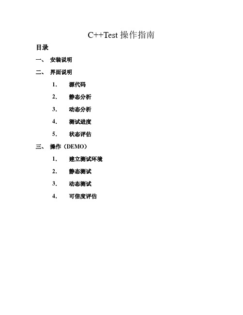
C++Test操作指南目录一、安装说明二、界面说明1.源代码2.静态分析3.动态分析4.测试进度5.状态评估三、操作(DEMO)1.建立测试环境2.静态测试3.动态测试4.可信度评估一、安装说明安装源程序:C++Test-21_jre.exe操作系统:Win2000英文版具体操作主要分三步走:第一步:打开安装源程序,同普通的windows应用程序一样,选择安装路径,完成安装。
第二步:从桌面或者菜单打开C++Test,将弹出类似于下面的一个窗口:这里的machine ID就是C++Test和主机绑定的信息。
这个machine ID需交给parasoft,来申请license。
而由于license的种类不同,可以分为local license (单机版)和net license(网络版)。
第三步:将相应的license和expire date粘贴到相应的位置,如果信息正确,系统将提示license ok。
如果信息不正确,系统将提示wrong license。
输入正确的license,打开C++Test,就可以进入C++Test的用户界面了。
二、界面说明1.源代码在源代码窗口可以看到我们所测试的代码,界面非常友好,当选择代码时,被选择的代码也会以蓝色块的形式出现。
并且,当我们进行了静态分析和动态分析时,这里我们也可以非常直观的观测到静态分析和动态分析的结果。
代码左侧的红色精灵帽表示静态分析时出现问题的所在,蓝色感叹号则表示动态分析时出现问题的所在。
点击相应的地方,会出现对问题的一个简单描述。
2.静态分析在静态分析栏中的Results标签是对静态分析结果的一个罗列。
每个红色精灵帽都代表一种违规行为,而它旁边的数字则代表测试代码中出现这种违规的次数。
紧接着的字母表明违规行为的严重级别。
再后面就是对这条规范的大致描述以及规则编号。
而标签Rules Manager则是对这些规则的管理,当用户需要使用某条规则的时候,只需要在相应规则左侧的方框内打上勾就表明选择了该条规则。
CFAST使用指南中文
程序简介1.1起步1.1. 1学习使用FAST1.2. 2硬件及软件配置1.1. 3安装1.2. 软件概述及适用范围1.2.1火灾模型的实用性1.2.2火灾1.2.3羽流及Layers1.2.4出口风流1.2.5热传导1.2.6物种浓度与密度1.2.7软件使用假设与范围1.3什么是用户使用界面(GUI)?1.3.1使用鼠标及其它定点设备1.3.2 GUI的有关术语1.3.3GUI界面按钮及菜单项1.4启动FAST1.5FAST主菜单2 创建程序输入数据2.1创建一新输入文件一实例2.2基本的火灾模型输入2.2.1输入输入文件的文件名2.2.2记录时间及电子表格输出2.2.3设置试验环境2.2.4定义若干空间结构2.2.5定义水平流之间的联系2.2.6定义竖直流之间的联系2.2.7增设水喷淋器和火灾探测器2.2.8定义火源2.2.9记录与时间相关的火灾实验曲线2.2.10工具集2.3高级火灾模型输入方法详解2.3.1建筑空气控制系统HV AC2.3.2HV AC系统通风口2.3.3HV AC系统内部连接与安装2.3.4HV AC系统通风管道2.3.5HV AC系统通风机2.3.6顶棚射流表面的选取2.3.7指定多个火源2.3.8顶棚到地板的热传导2.3.9定义目标层2.4交互式数据库2.4.1选取默认材料2.4.2选取默认对象2.4.3创建变换的数据库2.4.4编辑热物理数据库2.4.5编辑对象数据库对象火灾曲线61对象备注63闪火传播对象属性642.5修改配置文件2.6运行一个简单实例2.7新文件定义的标准过程2.8数据文件的打开和保存2.8.1选取一个已有的数据文件2.8.2创建一个新的输入数据文件2.8.3保存对数据文件的修改3运行火灾模型3.1进行模拟3.2边模拟边运行3.3处理模拟过程中的事件3.4保存模拟出的模型4复杂模型实例4.1事件4.2计算机分析4.3输入数据4.3.1输入文件名4.3.2定义外部条件4.3.3指定模拟时间和电子表格的输出4.3.4改变火灾房间的几何形状4.3.5改变通风口4.3.6改变火源的定义4.3.7保存对数据文件的修改4.4运行模型4.5模型运行结果5预测软件包5.1逃生时间5.2喷淋器与探测器的动作5.3房间烟气温度5.4上浮的热气压头5.5顶棚射流温度5.6顶棚羽流温度5.9通过开口的质量流5.10 羽流充填速率5.11辐射引燃5.12开口处的烟气流动5.13托马斯轰然公式5.14通风极限6 文件操作6.1改变路径6.2改变显示单位6.3设置色制和模式6.4输入数据的纠错6.5拷贝文件6.6打印文件6.7浏览文件6.8删除文件7 参考文献及附录文献信息FAST是一本有关火灾模型的使用工具手册他参考了以前的火灾模型CFAST并且增加了火灾形成过程提供了在分隔空间构筑物中的火现象的工程计算这本使用手册提供了使用范例及相关的资料详细介绍了软件的安装方法及使用指南关键词计算机模型计算机程序排空火灾模型火灾研究火险评价人的行为毒性订购信息美国NIST研究所FAST用户指南预测火灾发展与烟气蔓延的工程工具建筑火灾研究实验室美国NIST研究所简单的代数方程是工程计算的基础1984年Bukowski提出了用一系列独立的火灾计算来评估一个复杂,交互的过程,即,火危险分析[ 1 ]在1985年一系列适用于火灾评估的方程出版发行了尼尔森[ 3 ] 用 FIREFORM 和 FPE工具进一步扩展了这个概念并且提供了一广泛地在火灾安全工程计算中被使用的软件包这个软件包里提供了简单的工程计算模型1989年6月NIST研究所的火灾研究中心现BFRL的一下属机构针对火灾对居民人身安全的危害以及室内家具电线等物品的火灾时的相关危害发布了一种定量分析的方法这种分析方法经过6年的深入研究最终推出了第一代应用软件HAZARD I它是世界上第一代火灾模拟综合应用软件它结合了专家们的判断和计算的标准来评估一次特定火灾的后果FAST是建立在CFAST基础之上的一种程序集他提供有关框架结构的火险工程评估他是继HAZARD I 和FASTLite之后的应用在火险计算上的第二代软件FAST包括了以前FIREFROM中的独立的工程计算,是CFAST它包括了HAZARD I和FASTLite的更新版本他的用户界面与FASTLite相似本说明书提供了参考文献和应用实例以及使用指南说明了软件的安装等操作首先注意一点fast是针对火灾安全领域的专业人士设计的并且是对他们决策的补充软件的目的是对火灾灾害结果提供定量分析该模型只能在对计算的精确性进行证实性测试后在其允许的误差范围内使用然而正像许多其它计算机软件那样软件使用者提供的输入数据直接决定了计算结果的准确性如果有模型得到的预测结果精确性较差有可能导致错误的结论所以又该模型得到的所有结果都应该凭一般经验进行审核11开始FAST是建筑火灾蔓延的预测工具这张光盘中包括该软件及相关文件用户可按照说明书进行安装虽然该软件的安装及运行较简单但是要想更有效的使用该软件的各项功能用户必须阅读使用说明建议浏览一下软件使用说明书的目录熟悉该使用手册的内容1.1.1学习使用 FAST为典型火灾案例的现实模拟量建立恰当的输入数据的过程是比较复杂的当用若干典型参数来描述现实模拟量时几乎所有特定测试实例的数据都能被定制本使用说明中包括了所有的数据输入的详细描述这一节提供了一个可能的方案指导用户使用1第5页的1.2节对FAST的理论基础及预测方程使用的限制条件进行了概述2从第14页开始对用户界面中的每一项内容进行了详细的描述如鼠标键盘的使用数据输入界面及结果显示画面初学者有必要对本章进行学习以便熟悉图形用户界面的一些概念3在第23页的第2节介绍了一个单室火灾的简单范例提供了运行该实例的具体步骤学习本范例后用户将熟悉软件的基础操作4在第83页的第5节讲述了许多预测工具它们都包括在FAST软件中能用来对个别的火灾现象进行描述这些工具需要两个以上的输入参数大多数的程序只需要做相对较少的工作就可获得预测结果5最后在第25页第2.2节对FAST的数据输入进行了详细的描述它可用来定制个别测试实例的数据1.1.2硬件及软件配置要求1.1.3软件安装安装向导提示了必要的信息并拷贝必要的文件到硬盘上FAST是基于DOS环境下的程序应直接在DOS环境下安装如有必要在安装前可退出Windows环境及应用程序以下是安装步骤将安装光盘放入光驱输入如下命令D:INSTALL在安装的过程中有几个问题需要用户回答可根据自己的需要做适当的回答一般都是取默认值在每一个安装画面中安装向导都有相应的提示下面对安装步骤进行具体介绍将fast单独安装在一个目录中开始的两个安装画面显示了主程序的安装目录一般缺省为c安装程序至少需要12兆直接的空间当程序拷贝时安装向导将显示出安装进度为了能正确安装安装组件可能需要创建或是移动DOS中的启动文件CONFIG.SYS中的语句FILES=如果你要手动移动你可以跳过这个步骤FILES=语句至少要为该软件指定50个文件1. 2概述与局限预测火灾趋势的分析模型从60年代就开始发展经过30多年的发展与完善模型已相当成熟起初研究的重点是用数学语言描述火灾发展的三个阶段即发展蔓延熄灭这种与实际分离较大的数学表达方式仅为安全性分析提供了火灾燃烧现象的一小方面特征根据多重的单个现象的组合可以编制出复杂的计算机程序给出输入参数后就可以预测出预计火灾发生的原因这些分析模型经过发展已可以给出最符合工程实际应用的火灾状态的预测当前国际上已有36种火灾模型其中20种是预测火灾发生的环境温度19种预测烟气运动6种计算火灾的发展速率9种预测材料的耐火性4种计算火灾探测器与水喷淋器的灵敏度2种是计算火灾中人员疏散时间现在这些计算机模型在使用范围复杂程度使用目的等方面变化很大如单室火灾模拟程序ASET移植性很好对于单个房间内的火灾可给出较好的预测有些模型为了特定的使用目的提供了单一的功能如COMPF2程序计算发生跳火的房间温度LAVENT程序计算在一设有水平出口和风流减速帘的房间内顶棚射流的相互作用此外还有HARVARD 5 code 和FIRST用来预测单一房间内多个燃烧体的燃烧状态除了上面提到的单室火灾模拟程序外还有一些多室火灾模拟程序包括BRI HARVARD 6 code FASTCCFM CFAST 和 FASTLite所有的火灾模型都可分为两类一种是根据质量守恒动量守恒和能量守恒等基本物理定律建立的一种是根据实验做出曲线来找出个参数之间的关系这两类模型中都采用了数学近似及简化假设根据火灾的物理原理可建立数学表达式再将得出的守恒方程式代入温度烟气浓度等参数的预测方程并输入计算机就可得到解决方案发生火灾的环境是不断变化的所以这些方程通常为微分形式一个完整的方程组能计算出在一定时间内受限空间的火灾环境火灾模型假定在任何时候控制体内的温度烟气密度组分浓度等参数都相同不同的火灾模型将建筑物划分为数目不同的控制体目前应用最广的一类火灾模型称为区域模型通常它把房间分为两个控制体即上部热烟气层与下部冷空气层在发生火灾的房间里把火羽流或顶棚射流当作附加控制体可提高预测的准确性这种分层的方法来自对火灾实验的观察热烟气在顶棚聚集并从顶棚开始充满整个房间在实验中层中环境是不断变化的而两层厚度的变化更大所以区域模型在大多数火灾环境中可得到相当接近现实的模拟此外还有网络模型和场模型前者把每一间房间看成一个节点来预测远离起火房间某地点的环境而场模型则完全从另一个角度出发它把一个房间划分为上千甚至是上百万个网格它们能够用来预测层内的环境变化但是其运行时间大大超过区域模型所以只在细节计算中使用1.2.1 火灾模型的适用性在FAST中使用的CFAST模型是用来计算火灾期间建筑物内的烟气及温度的分布CFAST是基于解状态参数方程组的基础上的这些参数压力温度等是基于在一微小时间间隔内的焓与质量变化之上的这些方程式根据能量守恒质量守恒动量守恒以及理想气体定律而得到的这些守恒方程式是绝对正确的所以有火灾模型得到的错误结果只会是由方程的数学表达式及简单假设造成的上正确的限制条件用户应熟悉模型所遵循的火灾物理原理文献中提供的典型应用实例以及模型使用的限制条件1.2.2火源在CFAST中火源简化为一种以确定速率不断放热量的燃料通过燃烧,燃料的燃烧热转换为热焓l同时根据特定组分的产生率转化为该组分的质量在羽流和顶棚射流中也可以发生燃烧对手不受限火源燃烧将全部在羽流内进行对于受限火源燃烧可在任何有足够氧气的地方发生当一定的氧气被卷吸到火羽流中与未完全燃烧的燃料同时进入上部烟层上层内就可以发生燃烧接着是门道射流第二个房间上层第二个房间门道第三个房间上层直到燃料完全消耗或排到室外为止新版的CFAST可以在若干个房间中逐一监测多个火源这些火源全部作为分离的实体处理就是说它们与羽流没有相互作用与房间壁面之间没有辐射换热CFAST在计算火区增大时没有考虑燃料的热解模型因此设定火源与真实火源的相似程度如何将决定计算结果的准确性1.2.3羽流与气层在任何正在燃烧的物体上方都会形成羽流它不是任意气层的一部分但却是能量和质量由下层向上层输送的驱动源CFAST不使用点火源来近似羽流而是用经验公式决定由羽流引起的层间质量转移在不同层和不同房间之间能量和质量传输主要有两种形式一种是着火房间内的羽流另外一种是出现在门窗开口处的混合源在计算刚开始时室内每层的状态都与环境相同但为了避免计算中出现数学问题程序中预先假设上层的体积为房间体积的0001随着焓与质量由羽流送入上层上层体积开始膨胀层界面向下移动只要界面尚未到达开口的上缘就不可能有通过开口的流动在火灾的这种早期阶段上层气体的膨胀将使下层空气由开口流进相邻的房间一旦界面低于开口的上缘便开始形成门道羽流(也有人称为门道射流)随着烟气由起火房间流入相邻房间后一房间的下层空气受到挤压于是一部分空气可沿开口下部返流入起火房间在这种门道羽流中气体混合在流入与流出的逆向流边界上进行决定开口流动也按羽流处理不过这两者对空气的卷吸方式有差别因此直接使用羽流的计算方法会产生一些误差上述流动都是由压力差和密度差引起的而这两者又是由温度差和气层厚造成的因此得到正确流动的关键是在各层之间恰当分配来自火源的质量和焓1.2.4开口流开口流是火灾模型的控制现象因为它的波动很快并可在所有源项中迅速输送大量的焓开口流可分为水平流动和竖直流动两种类型前者如通过门窗的流动后者指的是流过房间顶棚或地板开口的流动对于火灾环境迅速变化的情况竖直流动很重要竖直流动不完全由上下气体的密度差决定还受气体的体积膨胀影响除了快速膨胀情况之外这种压差很小往往忽略不计但是若需了解小压差下的流动例如机械通风系统中产生的流动那么这种压差就变得很重要了大气压约为100,000Pa,火源产生的压力变化范围为11000h而机械通风系统产生的压差约为1100h为了正确解决它们的相互影响从问题整体来说应当能在100,000Pa的压力范围内考虑约01Pa的压差1.2.5传热在气层与房间壁面之间存在对流换热而墙壁顶棚和地板又以导热形式向外传热CFAST允许每个房间的墙壁地板和顶棚使用不同的材料但各个部分所用的材料性质应当相同同时每种壁面可分为三层按这些层分别进行导热计算,这有助于用户处理实际建筑物的结构材料的热物性是随温度改变的不过在通常的火灾温度范围内大多数物体的热物性变化不大因此在CFAST中将它们取为常数在火源气层和房间壁面之间还存在辐射传热其传热速率是温度差气体与壁面辐射率的函数火源和典型壁面间的辐射率变化很小气层的辐射率却随其组分浓度变化烟气中的颗粒C02水蒸气都是强辐射体因此组分浓度的误差将引起焓在不同层内分布的误差并由此而导致温度误差和流动误差1.2.6组分浓度模拟计算开始时各层的初始条件与环境相同初始温度由用户指定氧气和氮气的质量分数分别为23和77水分用相对湿度表示也由用户指定其它组分的浓度为零但随着燃料的热解多种组分开始生成质量并了解每层体积随时间的变化质量除以体积便是质量浓度将其与分子量结合起来又可得出体积百分比浓度或ppm浓度由此可见CFAST模型相当全面地考虑了物理化学流体流动与传热等方面在有些情况下可以直接使用质量能量和动量的基本定律但很多其它场合下必须使用经验公式乃至合理猜测来弥合现有知识的不足这些必要的假设可能会导致结果的不确定因此用户应当清除程序原有假定和局限性谨慎使用程序计算包括对关键参数取值范围的敏感性分析以便能够对结果的不确定性作出估计1.2.7假定与限制1.3什么是图形用户界面(GUI)?FAST的界面是普通的图形用户界面图形指使用直线矩形颜色阴影来表示出三维图形界面大多计算机操作人员一般都熟悉MS-WINDOWS界面FAST的界面具有WINDOWS应用程序的特征但它却不是一个WINDOWS的应用程序它是用DOS命令来启动的1.3.1使用鼠标或其他定点设备定点设备诸如鼠标轨迹球等是在GUI可视化应用程序中常用的手动设备本软件有三种鼠标操作方式单击双击拖动1.3.2GUI使用术语图形用户界面的设计可支持多个应用程序的同时运行程序有桌面窗口和标题栏在程序窗口左上角的一小方框内有一小横杠点击它可拖动窗口或双击关闭窗口在FAST界面中使用了两种类型的窗口最常用的是对话窗口用户在对话窗口中输入数据然后点击窗口下方的一排按钮确认或否定窗口中显示的数据上图就是一对话窗口的实例当对话框弹出后用户必须处理完对话窗口中的数据后才能对其他窗口或菜单进行操作对当前输入值点击OK Cancel或Esc进行确认或否定浏览窗口是作为图形用户界面的背景窗口用来概述地显示已输入的参数值在FAST中最常用的是火灾脚本浏览窗口用鼠标点击窗口的标题栏可拖动浏览窗口在图形用户界面中有若干数据栏它可显示信息也可供用户输入数据在FAST中不同类型的数据栏中可显示特性曲线及相关函数用户可参考本节的详细介绍已确定selectability, functionality,并且显示特性曲线在选择数据栏时按Tab键可选择下面的或右边的为当前数据栏按Shift+Tab键可选择上面的或左面的为当前数据栏当然用户也可用鼠标来点击选择下面就见介绍FAST界面中的各类型的数据澜标签用于提示用户输入参数的类型它没有外框并且是黑色字体弹出一红色的错误提示窗口用户必须纠正后才能进行下一项的输入这两个按钮用来确认或拒绝输入值或为相关的输入打开一个附加窗口当用鼠标单击或按Tab键移至到所选位置后按Enter键后相应的功能就会实现下拉选框它提供了用户所有可选择的输入项图标它使用了图形按钮来表明了每一个按钮的功能选择列表它提供了一个参数列表在列表中只能选择一个输入项当前选择项用蓝底白字标明而其它待选项用白底绿字表示可通过鼠标双击来选择输入项滚动条有时当窗口尺寸不够显示信息时一个垂直或水平滚动条会出现在窗口右边或下边以便用户调节并显示出别的信息编辑表它是一种电子表格蓝底白字在窗口底部有输入值的范围提示输入范围由单元格内的输入数据决定只有当程序确定输入值有效时用户才能跳到下一单元格进行输入单元格的选择用 来控制光标与指针I 与 是图形用户界面中两种常用的定位标识1.3.3图形用户界面中的菜单菜单提供用户选择各种功能及应用程序点击图标后就会弹出相应的菜单FAST的用户界面提供了3种菜单桌面菜单文件菜单及软件包菜单桌面菜单提供用户选择FAST的其他程序模块它可在桌面上弹出也可从火灾方案浏览窗口中点击桌面图标以显示出桌面菜单在下面1.5节中将对各菜单项详细介绍文件菜单中Save和Save As选项用来保存数据文件用户可在火灾方案浏览窗口中点击标题栏或磁盘图标就可弹出该菜单该软件包提供了几种快速计算程序可在桌面菜单种选择tools项或点击工具箱图标弹出该菜单在后面第5章中将有详细介绍cd \FASTFAST按回车键后FAST的启动窗口将显示在屏幕上按回车键后可显示出桌面菜单第一次运行程序时用户可以自定义各参数的单位所定义的一组参数将在以后的计算中使用如在本手册中通常使用了公制单位如温度压力长度能量能量释放率能量吸收率质量及时间分别使用了摄氏度帕米焦耳千瓦瓦千克以及秒作单位若要修改单位设置可点击下拉菜单选择列表中的单位例如温度单位的下拉菜单选项由开尔文摄氏度Rankine华氏温度点击桌面菜单选项Options再点击User Specified Units单位设定窗口就会显示1.5 FAST组件概述FAST是由几个互相依存的分析模块组成的 上面讨论的桌面菜单依据工作类型及典型的命令把这些模块编排在一起供用户选择运行点击Fil e将出现二级菜单Open / New Database选择Database可查看修改或选择关于热物性的交互式数据库Run的二级菜单项有Run Fire Mode l和Analyze Result s前者用来计算火灾和烟气的特性后者用于对计算结果提供几种解释选项以做进一步分析并且保存结果Tools提供几种快速计算工具计算出火灾的特性曲线如轰然和通过出口的质量流等事件Option s用来定制FAST程序组Utilities查看拷贝打印数据文件Hel p提供FAST主程序窗口中每一个图标的概述及版本信息和联系电话2. 创建FAST程序的输入数据FAST是一种交互式界面友好的用于创建输入数据文件运行CFAST模型的应用程序在本使用说明中要描述该程序的所有功能是比较困难的用户最好是通过使用来学习它这一节将详细描述FAST中所有窗口中的具体内容另外用户必须在熟悉图形用户界面GUI的基础上再学习本节内容2.1创建一个新的输入文件介绍一个简单的实例为了帮助初学者熟悉FAST的基本操作本节提供一简单的使用实例包括详细的软件使用命令为了便于说明我们对一两室火灾进行了模拟两间房间及房间与户外都有一扇门火源为居民家庭中常见的易燃品进入FAST的目录键入如下命令就将启动FASTCD\FASTFAST如果是第一次启动FAST需要对各参数单位进行初始化在FAST启动画面出现后程序主画面将出现用鼠标点击File New开始定义一新的火灾方案起初有两个步骤即对建筑物进行几何描述指房在点击New之后建筑结构选择窗口将出现在这个窗口中用户可定义房间数量及构造本节选择了2个房间的实例并定义了房间的尺寸为2.4米宽 3.6米深 2.4高确定完建筑结构之后还要对火源进行定义对于一大范围的火灾火势的发展可以用以下关系式来准确表述这里Q表示释热速率表示火灾强度系数t表示时间在三种火灾强度分别为600s300s150s75s达到1055KW1000 BTU/s我们分别称为慢速中速快速特大火灾它们对于火灾探测系统的设计都具有指导作用相应的这些火灾增长曲线都有通用的防火程序支持本例中用了一中等速度与T2成正比发展的火灾实例在若干可燃物中只要没有特别易燃的可燃物一般选择中速曲线用上文介绍的方法选择两个房间的建筑结构用鼠标点击Medium Growth图标点击OK之后关闭窗口一个新窗口将出现用来定义火灾曲线的时间本例中的默认值为300秒和900秒点击OK后关闭窗口2.2基本火灾模型参数的输入当一个文件建立或打开将出现火灾方案预览窗口该窗口能使用户在运行模型之前浏览文件的主要特征用户还能定义建筑物的房间数起火房间数红色方格表示配有喷淋器及探测器的房间数蓝绿色方格由于当前的CFAST模型主要是用来计算房间之间的烟气流动而不关心建筑物内实际的房间结构所以不必在意窗口中的房间模型与实际情况是否接近火灾方案预览窗口分为3个部分上部为标题栏第二部分是关于房间房间之间的烟气流动喷淋器及探测器的布置火灾曲线的定义最后一部分提供了运行火灾模型所必需的背景信息如外部条件文件名和输出时间等每部分具体的输入方法介绍如下在浏览窗口的第一部分每一个文件都有一独立的内容描述在窗口中部即建筑结构浏览部分显示了当前已定义的房间数目在每一个表示房间的小方格内都有标注说明了水平开口与垂直开口的数目如门和窗开口在数量后加标识H屋顶或地板上的开口在数量后加标识V起火房间用红色方格表示配置了喷淋器及探测器的房间用蓝绿色方格表示放置有其它可燃物的房间用黄色方格表示在激活建筑物结构部分的图标之前必须先选择一房间结构以决定该图标命令执行的方式点击输入文件中的#1房间然后点击它的图标这时#1房间的大小和建筑材料就将显示点击Cancel关闭此几何窗口再点击。
V2416A系列快速安装指南说明书

– 1 –– 2 – – 3 –P/N: 1802024160031*1802024160031*V2416A Series Quick Installation GuideEdition 2.2, June 2019OverviewThe V2416A-C2 uses the Intel® Celeron® 1047UE processor and the V2416A-C7 uses the Intel® Core™ i7-3517UE processor. Both models feature 4 RS-232/422/485 serial ports, dual 10/100/1000 Mbps LAN ports, 3 USB 2.0 hosts, and 2 CFast sockets. The computers provide 2 DVI-I outputs, making them particularlywell-suited for industrial applications such as rolling stock, SCADA, and automation systems.Most importantly, the V2416A computers come with 2hot-swappable storage trays for additional storage media, such as hard disks or solid-state drives. The hot swap support makesstorage replacement convenient, fast, and easy, and each storage tray has its own LED to indicate whether or not a storage module is plugged into the V2416A.Package ChecklistBefore installing your V2416A computer, verify that the package contains the following items: • V2416A series embedded computer • Wall-mounting kit• 8 screws for hot-swappable HDD trays • 8 HDD soft washers• 2 keys for hot-swappable HDD trays• Documentation and software CD or DVD • Quick installation guide (printed) •Warranty cardNOTE: If any of the above items are missing or damaged, notify your sales representative.V2416A Panel Layout V2416A Front ViewV2416A Rear ViewLED IndicatorsThe following table describes the LED indicators located on the front and rear panels of the V2416A.LED Name LED Color LED Function Power Green Power is on and functioning normallyOffPower is off or power error existsStorage Yellow CFast card/HDD/SSD is transmitting dataOff CFast card/HDD/SSD is not transmittingdataLAN (1 or 2) Green100 Mbps Ethernet modeYellow1000 Mbps Ethernet mode Off 10 Mbps or no activityTX (P1-P4) Green Serial port is transmitting dataOff Serial port is not transmitting dataRX (P1-P4) Yellow Serial port is receiving dataOff Serial port is not receiving dataL1/L2 Green Disk is inserted correctly into storage trayBlinking Disk is ready to be removed Off Storage tray is emptyInstalling the V2416AThe V2416A can be DIN-rail mounted, wall mounted, or VESA mounted. Some mounting kits may need to be purchased separately. Refer to the V2416A Hardware User’s Manual for detailed installation instructions.Connector DescriptionPower ConnectorConnect the 12 to 48 VDC LPS or Class 2 power line to V2416A’s M12 A-coded power connector. If the power is supplied properly, the Power LED will light up. The OS is ready when the Ready LED glows a solid green.Grounding the V2416AGrounding and wire routing help limit the effects of noise due to electromagnetic interference (EMI). Run the ground connection from the ground screw to the grounding surface prior to connecting the power.SG (Pin 5): The shielded ground(sometimes called protected ground) contact is the central pin of the power input connector. Connect the SG wire to an appropriate grounded metal surface.DVI-I OutputsThe V2416A comes with 2 DVI-I female connectors for the DVI display. The DVI output interfaces are located on the front panel of the product. Be sure to use the correct cable to connect the computer to the display.– 4 –– 5 –– 6 –/supportThe Americas: +1-714-528-6777 (Toll-free: 1-888-669-2872)Europe: +49-89-3 70 03 99-0 Asia-Pacific: +886-2-8919-1230India: +91-80-4172-9088 China: +86-21-5258-9955 (Toll-free: 800-820-5036)2019 Moxa Inc. All rights reserved.CFast SlotThe V2416A has 2 CFast sockets. One slot is located on the front panel for OS storage and the other slot is located inside the V2416A for backup storage. Both slots support CFast Type-I/II with DMA mode.To install an OS CFast card, remove the outer cover and insert the CFast card in the socket. When finished, push the cover into the socket and refasten the screws.To install a CFast card for backup storage, purchase a CFast card through Moxa’s CTO* service. Refer to the V2416A datasheet for more information.*CTO = Configure to order USB HostsThe V2416A has one USB port with an M12 D-coded connector on the front panel, and two USB ports with type-A connectors on the rear panel. These USB ports can be used to connect flash disks for storing large amounts of data.Hot-swappable Storage TraysThe V2416A computers have two slots for additional storage media. Both slots support hot swapping for convenient, fast, and easy storage expansion. Refer to the Hardware User’s Manual for detailed storage installation.To eject a storage unit, first press the hot-swap button for that tray. When the LED starts to blink, unfasten the two screws for the corresponding storage tray, rotate the lock counterclockwise using the key provided in the package, and then pull out the hot-swappable storage tray. Ethernet PortsTwo 10/100/1000 Mbps Ethernet ports using M12 X-codedconnectors are located on the front panel. The pin assignments are shown below:Serial PortsThe serial ports use DB9 connectors. Each port can be configured by software for RS-232, RS-422, or RS-485. The pin assignments for the ports are shown in the following table: Pin RS-232 RS-422 RS-485 (4-wire) RS-485(2-wire)1 DCD TxDA(-) TxDA(-) –2 RxD TxDB(+) TxDB(+) –3 TxD RxDB(+) RxDB(+) DataB(+)4 DTR RxDA(-) RxDA(-) DataA(-)5 GND GND GND GND6 DSR – –– 7 RTS – – – 8 CTS – ––DI/DOThe V2416A comes with a 6-channel digital input and 2-channel digital output on the terminal block connectors. Audio InterfaceThe V2416A comes with an M12 A-coded audio connector for audio input and audio output, allowing users to connect a speaker or an earphone. Pin No. Audio1 Line in – Right2 GND3 Line in – Jack Detect4 Line in – Left5 Line out – Left6 Line out – Jack Detect7 Line out – Right 8GNDReset ButtonPress the “Reset” Button on the rear panel of the computer to reboot the system automatically. The Ready LED will blink on and off for the first 5 seconds, and then maintain a steady glow once the system has rebooted. Real-Time Clock (RTC)The V2416A’s real-time clock is powered by a lithium battery. You can easily replace the battery yourself using an optional battery kit*. However, please note that there is a risk of explosion if the battery is replaced by an incorrect type of battery. Refer to the V2416A Hardware User's Manual or contact a qualified Moxasupport engineer if you have any questions about the RTC battery. *Moxa offers an RTC battery kit that you can use to easily replace the battery. For details, check the optional accessories section of the V2416A datasheet.Powering on the V2416ATo power on the V2416A, connect the power cable to the V2416A’s M12 A-coded power connector (located on the rear panel). Press the power button to turn on the computer. Note that the Shielded Ground wire should be connected to the central pin of theconnector. It takes about 30 seconds for the system to boot up. Once the system is ready, the Power LED will light up.Configuring the Ethernet InterfaceW7E users should follow these steps:1. Go to Start → Control Panel → Network and Internet →View network status and tasks → Change adapter setting .2. In the Local Area Connection Properties screen, click InternetProtocol (TCP/IP) and then select Properties . Select Internet Protocol Version 4, and then click Properties . 3. Click OK after inputting the proper IP address and netmask.。
数字电子公司 PS-365 A 到 PS-4600 替换指南说明书
Easy! Smooth!PS-365*A PS-4600 Replacement GuidebookIntroductionThis document introduces the procedures and notes for replacing the PS-365*A with the PS-4600.The recommended substitute model is listed below.Equipment in use Recommended substitute modelPS-3650A *1 (Expansion slot x 1) Model code: PS3650A-T42(-24V)PS-4600 (Expansion slot x 1)Model code: PFXP*161E******N00PS-3651A *1 (No expansion slot) Model code: PS3651A-T42(-24V)PS-4600 (No expansion slot)Model code: PFXP*160D******N00*1 Sales terminated as of March 2014Interpreting the PS-4600 Series Model CodeA portion of the PS-4600 Series model code differs according to the specification. When purchasing the PS-4600 Series, carefully check the model code to order before making your purchase.Digit number5 7 89 10 11 12 13 14 15 16 Front bezel Aluminum Standard Model PRear Mount Model F Display 12-inch (XGA) 6 Expansion slot *10 slot 0 1 slot = 1 PCI 1 1 slot = 1 PCI Express C 2 slots = 1 PCI + 1 PCI Express 2 2 slots = 2 PCI ACPU type Intel ® Celeron ®M 827E 1.4GHz D Intel ® Core TM i3 3217UE 1.6GHz EPower supplyACA DC with interface for UPS Battery UnitB DCD AC with interface for UPS Battery Unit UMemory1GB 1 2GB2 3GB(2GB+1GB)3 4GB4 6GB(4GB+2GB) 6 8GB8 12GB(8GB+4GB) C 16GB(8GB+8GB)G*1 The number in parentheses indicates the number of PCI Express lanes.To conform to the PL-365*A, 1 or 0 slot is recommended in this document. However, if you wish to use more PCI slots when making the replacement, the 2 slot model can also be selected.Digit number578910 11 12 1314 15 16 OSNone 0Windows ®Embedded Standard 2009 MUI(32-bit) 1Windows ®XP Pro Japanese Version 2Windows ®XP Pro MUI 3Windows ®Embedded Standard 7 MUI (32-bit) 4Windows ®7 Ultimate MUI (32-bit) 5Windows ®7 Ultimate MUI (64-bit) 6 StorageNone N CFast (4GB) G CFast (8GB) H CFast (16GB) J Primary CFast 4 GB + Secondary CFast 4 GB(for Windows ® Embedded Standard 2009 MUI) LPrimary CFast 8 GB + Secondary CFast 4 GB(for Windows ® Embedded Standard 7 Premium MUI) MHDD(500GB) with FAN P SSD(60GB) T SSD(128GB) U Slide-inEquipmentNone0 DVD multi drive 1 HDD(500GB) 2 SSD(60GB) 3Options None0 COM Expansion Board (RS-232C/422/485)4 COM Expansion Board + COM Expansion Board(RS-232C/422/485) WSoftware Bundle None N WinGPGContentsIntroduction 2 Interpreting the PS-4600 Series Model Code 3 Contents 5 Chapter 1. Specification Comparison 7 1.1 PS-3650A and PS-4600 (1 slot) specification comparison7 1.2 PS-3651A and PS-4600 (0 slot) specification comparison10 Chapter 2. Hardware Compatibility 132.1 Differences in function locations13◆PS-3650A and PS-4600 (1 slot) function locations13◆PS-3651A and PS-4600 (0 slot) function locations162.2 External dimensions19 2.3 Intelligent fan control19 2.4 Battery backup UPS19 2.5 Serial interfaces19 2.6 USB interface19 2.7 DVD-RW drive20 2.8 External HDD, SSD, CFast card, USB devices20 2.9 Power supply plug21 2.10 Power consumption21 Chapter3. Compatibility with Accessories 22 3.1 Individual accessories22 3.2 Maintenance accessories22Chapter 4. Software Compatibility 23 4.1 Supported operating systems23 4.2 Supported operating system languages23 4.3 Supported software25 4.4 Functions supported by System Monitor25 Chapter 5. Appendix 26 5.1 FP-3000 Series265.1.1 Connection with the PS-4600265.1.2 Remote installation distances and cables265.1.3 Required touch panel driver27 5.2 Uninterruptible power supply (UPS)285.2.1 Overview285.2.2 Specifications295.2.3 Dimensions29 5.3 INtime OS30Chapter 1. Specification Comparison1.1 PS-3650A and PS-4600 (1 slot) specification comparisonDisplay specificationsPS-3650A PS-4600 (1 slot)Display deviceTFT color LCD (12-inch) Graphics XGA (1,024 x 768 pixels) Displaycolors/gradation260,000 colorsUP! 16 million colors Backlight Cold-cathode tube (replaceable) LED backlight (not user replaceable, send-back type) Brightness adjustment 4 levels (adjust on Windows ®control panel)UP! Step-less adjustmentDisplay devicelifespan50,000 hoursBacklight lifespan 60,000 hours or more50,000 hours or more Touchpanel TypeAnalog resistiveResolution 1,024 x 1,024 UP! 4,096 x 4,096Performance specifications PS-3650A PS-4600 (1 slot) CPU Intel ® Celeron ®M (1.5GHz) UP! Intel ® Core TM i3 (1.60GHz)L2 cache 1 MB UP! 3 MBMain memory 1 slots (1 GB max) (DDR 333 MHz) UP! 2 slots (16 GB max) (DDR3 1,600 MHz) Chipset Intel ®855GME + ICH-4 Intel ® QM77 Graphics controller Onboard Intel ® 855GME Intel ® HD Graphics 4000 Video memory64 MB max(Allocated from main memory)UP! 1 GB(Allocated from main memory)Video output Analog-NEW!QXGA (2,048 x 1,536 pixels) orlower DigitalNEW!FHD (1,920 x 1,200 pixels) orlowerGeneral specificationsPS-3650A PS-4600 (1 slot)Panel cut dimensions W301.5 x H227.5 mm [W11.87 x H8.96 in.]External dimensions W313 x H239 x D103 mm[W12.32 x H9.41 x D4.06 in.]W313 x H239 x D114.2 mm[W12.32 x H9.41 x D4.50 in.]→See 2.2Front bezel material Die cast aluminum AluminumWeight Approx. 4.5 kg (9.9 lbs) Approx. 4.1 kg (9.03 lbs) Cooling method Forced air cooling by fanUP! Forced air cooling by fan (Intelligent fan control)→See 2.3Power supply →See 2.9AC power supply: 100 to 240 V, DC power supply: 24 V PowerconsumptionAC powersupply110 VA or lower 130 W or lower →See 2.10 DCpower supply80 W or lower 130 W or lower →See 2.10Battery backupUPSOptional(AC power supply only)UP! Optional →See 2.4Interface specificationsPS-3650A PS-4600 (1 slot)Serial(9-pin D-sub plug)RS-232C x 1 RS-232C x 2 RS-232C/422/485 x 1 RS-232C/422/485 (optional)x 2→See 2.5RS-232C (RI/+5V switchable) x 2 -RAS 25-pin D-sub plug -DiskSATA -NEW!Slide-in disk: (HDD/SSD/CFastadaptor Unit) x 1Slide-in slot: (HDD/SSD/DVD-RW)x 1CFast card slot x 1→See 2.7IDE CF card(Type-I, Type-II) x 1 -USB→See 2.6USB x 4(USB 2.0 compatible, Type-A)Front USB x 1(USB 1.1 compatible, Type-A)USB x 4(USB 3.0 compatible, Type-A)Front USB x 1(USB 2.0 compatible, Type-A)Ethernet LAN1 10BASE-T/100BASE-TX autoswitchingUP!10BASE-T/100BASE-TX/1000BASE-T auto switchingLAN2 10BASE-T/100BASE-TX/1000BASE-T auto switchingPCMCIASide x 1PCMCIA Type II cards can be used.CARD BUS support(Excluding VIDEO ZOOM, SOUNDfunctions)-Sound Line output UP! Line input or mic input/ line outputDVI - NEW! DVI-I x 1PCI PCI 1 slot (Rev. 2.2)1.2 PS-3651A and PS-4600 (0 slot) specification comparisonDisplay specificationsPS-3651A PS-4600 (0 slot)Display deviceTFT color LCD (12-inch) Graphics XGA (1,024 x 768 pixels) Displaycolors/gradation260,000 colorsUP! 16 million colors Backlight Cold-cathode tube (replaceable) LED backlight (not user replaceable, send-back type) Brightness adjustment 4 levels (adjust on Windows ®control panel)UP! Step-less adjustmentDisplay devicelifespan50,000 hoursBacklight lifespan 60,000 hours or more50,000 hours or more Touchpanel TypeAnalog resistiveResolution 1,024 x 1,024 UP! 4,096 x 4,096Performance specifications PS-3651APS-4600 (0 slot)CPU Intel ® ULV Celeron ® M (1 GHz)UP! Intel ® Celeron ® M 827E(1.4 GHz) L2 cache 512 KBUP! 1.5MBMain memory 1 slot (1 GB max) (DDR 333 MHz)UP! 2 slots (16 GB max) (DDR3 1,600 MHz)Chipset Intel ® 855GME + ICH-4 Intel ® HM76 Graphics controller Onboard Intel ® 855GME Intel ® HD Graphics 3000Video memory64 MB max(Allocated from main memory)UP! 1 GB(Allocated from main memory)Video output Analog-NEW!QXGA (2,048 x 1,536 pixels) orlower DigitalNEW!FHD (1,920 x 1,200 pixels) orlowerGeneral specificationsPS-3651A PS-4600 (0 slot)Panel cut dimensions W301.5 x H227.5 mm [W11.87 x H8.96 in.]External dimensions W313 x H239 x D60 mm[W12.32 x H9.41 x D2.36 in.]W313 x H239 x D59.5 mm[W12.32 x H9.41 x D2.35 in.]→See 2.2Front bezel material Die cast aluminum AluminumWeightApprox. 3.8 kg (8.4 lbs)Approx. 4.0 kg (8.81 lbs) Cooling method Natural cooling (fanless)Natural cooling (fanless)(When an HDD is not mounted onSlide-in Disk) →See 2.3Power supply →See 2.9AC power supply: 100 to 240 V, DC power supply: 24 V Power consum ptionAC power supply95 VA or lower130 W or lower →See 2.10DC power supply40 W or lower 130 W or lower →See 2.10Battery backupUPSOptional(AC power supply only)UP! Optional →See 2.4Interface specificationsPS-3651A PS-4600 (0 slot)Serial(9-pin D-sub plug)- RS-232C x 2 RS-232C/422/485 x 1 RS-232C/422/485 (optional)x 2→See 2.5RS-232C (RI/+5V switchable) x 1 -RAS 25-pin D-sub (plug) -DiskSATA -NEW!Slide-in disk: (HDD/SSD/CFastadaptor Unit) x 1Slide-in slot: (HDD/SSD/DVD-RW)x 1CFast card slot x 1IDE CF card(Type-I, Type-II) x 1 -USB→See 2.6USB x 4(USB 2.0 compatible, Type-A)Front USB x 1(USB 1.1 compatible, Type-A)USB x 4(USB 3.0 compatible, Type-A)Front USB x 1(USB 2.0 compatible, Type-A)Ethernet LAN1 10BASE-T/100BASE-TX autoswitchingUP!10BASE-T/100BASE-TX/1000BASE-T auto switchingLAN2 10BASE-T/100BASE-TX/1000BASE-T auto switchingPCMCIASide x 2PCMCIA Type II, Type III cardscan be used.CARD BUS support(Excluding VIDEO ZOOM, SOUNDfunctions)-Sound Line outputUP!Line input or mic input / line outputDVI - NEW! DVI-I x 1 PCI -Chapter 2. Hardware Compatibility2.1 Differences in function locationsThe locations of the various functions differ on the PS-365*A and the PS-4600 as shown below.◆PS-3650A and PS-4600 (1 slot) function locationsPS-3650A PS-4600 (1 slot)A Power supply LED/RAS status lamp Status LED (power supply)B HDD/IDE Access lamp (DISK) Status LED (Disk access)C Front coverD Hardware Reset Switch (RESET) Power/ Reset buttonsE Front USB interfaceF Power switch(AC power supply only) G Power supply connectorH Mask Cover - I Expansion Board Base - J Expansion Board Cover - K Expansion Board Support -L Fan Unit Fan Unit(When an HDD is mounted on Slide-in Disk)M Memory SlotN - Ground connectionO USB interface x 4P PCMCIA Slot Cover -Q Ethernet interface (LAN1/LAN2)R Speaker output Line input or mic input / line outputS RAS interface (RAS) / Serial Interface (RS-232C)-T Serial I/F (RS-232C/422/485) Serial I/F (RS-232C) x 2U CF Card Cover -V Expansion slot PCIW - Slide-in Disk(HDD/SSD/CFast adaptor Unit)X - CFast slot/Connection Y - Slot expansion and Slide-in Slot(HDD/SSD/DVD-RW)Z - DVI-I interface 1 - Add-on interface module slot x2(RS-232C/422/485 I/F or UPS I/F)2 - Backup lithium battery◆PS-3651A and PS-4600 (0 slot) function locationsPS-3651A PS-4600 (0 slot)A Power supply LED/RAS status lamp Status LED (power supply)B HDD/IDE Access lamp (DISK) Status LED (disk access)C Front coverD Hardware reset switch Power/ Reset buttonsE Front USB interfaceF Power switch(AC power supply only) G Power supply connectorH Mask Cover -I - Ground connection L - Fan Unit(When an HDD is mounted on Slide-in Disk)M Memory Slot N DISK Cover-O USB interface x 4P PCMCIA Slot Cover -Q Ethernet interface (LAN1/LAN2)R Speaker output Line input or mic input / line outputS RAS interface (RAS) / Serial Interface (RS-232C)-T Serial I/F (RS-232C/422/485) Serial I/F (RS-232C) x 2U CF Card Cover -W - Slide-in Disk(HDD/SSD/CFast adaptor Unit)X - CFast slot/Connection Z - DVI-I interface 1 - Add-on interface module slot x2(RS-232C/422/485 I/F or UPS I/F)2- Backup lithium battery2.2 External dimensionsCompared with PS-365*A, the depth of PS-4600 is large (about 9 mm larger).Vertical space is changed from 50 mm to 100 mm.A guide to ensure the amount of space necessary to safely install the product is listed below.Vertical, back Horizontal2.3 Intelligent fan controlIn PS-4600, a fan is attached to the Slide-in Disk when an HDD is mounted. When fanless is required, specify other than “P” for 13rd digit of the model code in the built-in shipping options. When a fan is attached later when an HDD is mounted on the Slide-in Disk, please contact our support division because it is necessary to update the software.The fan speed for PS-4600 models equipped with a fan is controlled according to the internal temperature. The fan does not operate until the internal temperature reaches a specific temperature.2.4 Battery backup UPSBy equipping the PS-4600 with a UPS battery unit, power can continue to be supplied even when there is a loss of power due to a power failure and running programs can be correctly terminated by the UPS software.To connect a UPS battery unit, specify "B" or "U" for the 10th digit of the model code in the built-in shipping options.2.5 Serial interfacesFor PS-4600, up to 2 ports of serial interfaces which correspond to a communication method (RS-232/ 422/485) can be added. (When a UPS is selected, only 1 port is added.) In the case of addition, specify “4” or “W” for the 15th digit of the model code in the built-in shipping options. To perform RS-422/485 communication with the additional serial interface, software is required to switch the RTS lines each time the driver sends or receives data. The RTS lines are not switched automatically.The PS-4600 also uses COM3 internally as the touch panel interface. When adding additional COM ports with expansion boards or USB-SIO, do not use COM3.2.6 USB interfaceThe PS-365*A can be configured not to use the front USB port with the DIP switches, but the PS-4600 does not have this setting.The Rear Mount Model PS-4600 is not equipped with a USB interface on the front of the touch panel, so there are 4 ports total.2.7 DVD-RW driveThe DVD-RW drive is connected to the slide-in slot. An expansion slot is required for the slide-in slot. Specify other than “0” for 8th digit of the model code in the built-in shipping options. When an HDD or SSD is connected to the slide-in slot, the DVD-RW drive cannot be used. Separately prepare a commercially available DVD drive that can connect via USB.2.8 External HDD, SSD, CFast card, USB devicesWhen an external HDD, SSD, CFast card or USB device is connected to a PS-4600 pre-installed with Microsoft Windows Embedded Standard, the system will no longer start. In this situation, the system can be started with the device connected to it by configuring the setting below in the BIOS boot menu.ConditionBIOS settingWhen using only a CFast card with OS installed Set [SATA 1 Drive] for the [1st Boot Device]settings.When using a CFast card with OS installed and another CFast card for storage Set [SATA 0 Drive] for the [1st Boot Device] settings.*The notes above are included with models pre-installed with Microsoft Windows ® Embedded Standard.Select from HDD, SSD or DVD-RW2.9 Power supply plugCaution: The power line terminal locations for the power supply plug differ between thePS-365*A and the PS-4600.PS-365*A PS-4600A C p o w e r s u p p l yD C p o w e r s u p p l y2.10 Power consumptionThe power consumption does not include the value of power supplied to devices in the provided expansion slots and to USB devices. The maximum power consumption of the entire product including the value of supplied power is 130 W. Power supply cable AC connector Power supplycable AC connectorPower supply cableDCconnector Power supply cable DC connectorChapter 3. Compatibility with Accessories3.1 Individual accessoriesIndividual accessories for the PS-365*A and their compatibility are listed below.Product name Model code *PS-3650A PS-3651APS-4600DIM module DDR2 512 MB PSA-DDR512✓✓x1 GB PSA-DDR1G✓✓x HDD unit 250 GB PS365XA-250✓✓x CF card 128 MB CA3-CFCALL/128MB-01 ✓✓x256 MB CA3-CFCALL/256MB-01 ✓✓x512 MB CA3-CFCALL/512MB-01 ✓✓x1 GB CA6-CFCALL/1GB-01 ✓✓x2 GB CA8-CFCALL/2GB-01 ✓✓x CF card adapter GP077-CFAD10 ✓✓x Industrial hub SPIDER8TX-PRO ✓✓✓USB front attachment cable (1 m) CA5-USBEXT-01 ✓✓✓Screen protection sheet (5 pcs.) CA7-DFS12-01 ✓✓✓* Please check the model code/global code table at /product/globalcode.html.3.2 Maintenance accessoriesMaintenance accessories for the PS-365*A and their compatibility are listed below.Product name Model code *PS-3650A PS-3651APS-4600Replacement battery unit PS365XA-BATTU ✓✓x Drip-proof packing CA3-WPG12-01 ✓✓x Backlight CA8-BLU12XGA-01 ✓✓x Mounting hardware CA3-ATFALL-01 ✓✓x AC power supply connector (straight) (5 pcs.) CA7-ACCNL-01 ✓✓x DC power supply connector (straight) (5 pcs.) CA7-DCCNL-01 ✓x xDC power supply connector (right angle) (5 pcs.) CA5-DCCNL-01 ✓✓x* Please check the model code/global code table at /product/globalcode.html.Chapter 4. Software Compatibility4.1 Supported operating systemsThe supported operating systems for the PS-365*A and the PS-4600 are listed below.OS PS-365*A PS-4600Windows® XP Professional Japanese ✓✓Windows® XP Professional Multi-Language ✓✓Windows® XP Embedded Multi-Language ✓xWindows® Embedded Standard 2009 x ✓Windows® Embedded Standard 7 x ✓Windows® 7 Ultimate x ✓4.2 Supported operating system languagesThe supported operating system languages differ between the PS-4600 and the PS-365*A. They are listed in the table on the following page.* The abbreviations and symbols in the table have the following meanings.✓Supported.△The language can be used by installing the language pack provided with "Otasuke Pro!". Download from the URL below./otasuke/download/ps/ps4000/wes7lang.htmx Not supported.WinXP Windows® XP Professional JapaneseWinXP ML Windows® XP Professional Multi-LanguageXPE ML Windows® XP Embedded Multi-LanguageWES2009 Windows® Embedded Standard 2009WES7 Windows® Embedded Standard 7Win7 Windows® 7 Ultimate365*A PS-365*A4600 PS-4600LanguageWinXP WinXPMLXPEMLWES2009 WES7 Win7 365*A 4600 365*A 4600 365*A 4600 4600 4600Arabic x x x ✓△✓△✓Bulgarian x x ✓✓x x △✓Chinese (Simplified) x x ✓✓△✓△✓Chinese (Traditional) x x ✓✓△✓△✓Croatian x x ✓✓x x △✓Czech x x ✓✓△✓△✓Danish x x ✓✓△✓△✓Dutch x x ✓✓△✓△✓English x x ✓✓✓✓✓✓Estonian x x ✓✓x x △✓Finnish x x ✓✓△✓△✓French x x ✓✓✓✓✓✓German x x ✓✓✓✓✓✓Greek x x ✓✓△✓△✓Hebrew x x x ✓△✓△✓Hungarian x x ✓✓△✓△✓Italian x x ✓✓✓✓✓✓Japanese ✓✓x ✓✓✓✓✓Korean x x x ✓△✓△✓Latvian x x ✓✓x x △x Lithuanian x x ✓✓x x △✓Norwegian x x x ✓△✓△✓Polish x x ✓✓△✓△✓Portuguese x x ✓✓△✓△✓Portuguese (Brazil) x x ✓✓△✓△✓Romanian x x ✓✓x x △✓Russian x x ✓✓△✓△✓Serbian Latin x x x x x x △✓Slovak x x ✓✓x x △✓Slovenian x x ✓✓x x △✓Spanish x x ✓✓✓✓✓✓Swedish x x ✓✓△✓△✓Thai x x ✓✓x x △✓Turkish x x ✓✓△✓△✓Ukrainian x x x x x x △✓4.3 Supported softwareThe software that the PS-4600 supports is listed below.Software WinGP *1✓Utilities System Monitor ✓Backlight brightness adjustment ✓Touch panel driver *2✓Keyboard emulator *3✓Remote shutdown xEWF Setting Tool *4✓XP Embedded CF card backup/recovery tool *5xLang Shell *6xLanguage selection Shell update *7✓API-DLL *8System Monitor x EWF x*1 When WinGP was installed on the PS-365*A and RS-422/485 communication was being performed, the PS-365*A cannot be replaced with the PS-4600 as is.→See 2.6*2 The PS-365*A driver is DMC's UPDD, but the PS-4600 uses software called Touch Screen.Please be aware that right click operations change to touch and hold.The touch sound is also issued when the finger is lifted from the screen, not when the screen is pressed. *3 Use the user assistance screen keyboard standard in Windows® 7 Ultimate and Windows® Embedded Standard 7.*4 The PS-365*A was RAM mode, but the PS-4600 changes to RAM REG.*5 The PS-365*A had a dedicated tool, but the PS-4600 does not support it.When backup/recovery is required, prepare a normal tool (commercially available product, free software).*6 Can be configured with the Windows® Embedded Standard 7 standard function.*7 Only supported by Windows® Embedded Standard 7.*8 API-DLL is not supported.4.4 Functions supported by System MonitorThe System Monitor functions that the PS-4600 supports are listed below.Monitor item Error Action Monitor item Error Action Voltage DOUT x Watchdog Timer DOUT x LED x LED xBuzzer x Buzzer xPopup Message x Popup Message xShutdown x Shutdown x Fan *1DOUT x Hardware Reset x LED ✓SMART DOUT xBuzzer ✓LED ✓Popup Message ✓Buzzer ✓Shutdown ✓Popup Message ✓Temperature DOUT x DIN DOUT x LED ✓LED xBuzzer ✓Buzzer xPopup Message ✓Popup Message xShutdown ✓Shutdown x Backlight DOUT x Remote Reset - x LED x Remote RAS - xBuzzer xPopup Message x*1Only when an HDD is mounted on the slide-in Disk.Chapter 5. Appendix5.1 FP-3000 Series5.1.1 Connection with the PS-4600The PS-4600 can connect to the FP-3000 Series by DVI * or analog RGB. PS-4600 images can also be output to a separate location.* Its Rev.2 or later of FP3000 Series supports DVI5.1.2 Remote installation distances and cablesThe distances the FP-3000 Series can be remotely installed and the cables that support those distances are listed below.Cable Model code 5 m Analog RGBCA7-CBLCVRGB-01 or CA7-CBLCDVI-D/RGB-01 + FP-CV02-45DVI FP-DV01-50 *1USB FP61V-IS00-O or FP-US0010 m DVI PFXZPBCBDV101 *2*1 To connect the FP-3000 Series to the PS-4600 Series, only revision "2" FPs with the symbol can be used. *2 The maximum cable length for DVI standard is 5m. Because the 10m cable is non-standard, the exact performances is not guaranteed. According to environment or equipment configuration, video images may not be displayed properly, so be sure to check performances every time environment or equipment configuration is changed. A 5m cable is recommended when using in SXGA resolution or higher.FP3000 SeriesPS-4600DVI-I or Analog RGB5.1.3 Required touch panel driverThe required touch panel driver for each monitor is listed below.OSPS-4000 Series FP-3000 SeriesPS-4600 FP-3710T FP-3710K/FP-3900T FP-3600T *1/ FP-3650TWinXP JP,WinXP ML, WES2009 Touch ScreenUPDD Win7, WES7 TSC-DD*1 Win7 and WES7 do not officially support a SVGA (800 x 600 pixels) resolution, but we have verified thatthe screen is displayed without problems.WinXP JP Windows ®XP Professional JapaneseWinXP ML Windows ® XP Professional Multi-Language WES2009 Windows ® Embedded Standard 2009 WES7 Windows ® Embedded Standard 7 Win7 Windows ® 7 UltimateFP3000 SeriesPS-4600Touch ScreenWin7Touch ScreenWinXP5.2 Uninterruptible power supply (UPS) 5.2.1 OverviewAn uninterruptible power supply (UPS) option can be used for both AC and DC power supply type. The diagram below shows PS4600 with the UPS attached.Attach a UPS I/F board to an IF 1 of an expansion interface module.1: UPS battery unit (model code: PFXZPSEUUPB2)2: UPS connection cable 3 m (model code: PFXZPSCBUP32)3: PS-4600 Series equipped with the UPS interface board (model code: PFXZPSIUUPM2*)Primary features of the UPS option:・Rechargeable battery that is maintenance free and lasts a long time ・Communication over the built-in interface ・Temperature sensor ・Over discharge protection* You must specify "B" or “U” for the 10th digit of the model code in the built-in shipping options. It is possible for a user to purchase an UPS as an option and attach it to the main unit later.PS-4600 Uninterruptible Power Supply (UPS)5.2.2 SpecificationsBattery: Type MethodHawker Cyclon 12 Vdc 4.5 Ah (2 connected in series)Single cell (X cell) Rated Voltage24 VdcBattery Charging Current2.88 A maximum Deep discharge protection YesShort circuit protection Yes (This does not apply to the connected battery unit.)Power consumption 15.0 W maximum at 0.5AStatus indicator Displayed in System Monitor utility Configuration Configured with System Monitor utility5.2.3 Dimensions5.3 INtime OSPS-4600 is scheduled to support the INtime OS. For details, contact TenAsys Corporation. http://www.mnc.co.jp/INtime//products/intime.php。
CFAST使用指南
1 程序简介1.1起步1.1.1学习使用FAST1.2.2硬件及软件配置1.1.3安装1.2.软件概述及适用范围1.2.1火灾模型的实用性1.2.2火灾1.2.3羽流及Layers1.2.4出口风流1.2.5热传导1.2.6物种浓度与密度1.2.7软件使用假设与范围1.3什么是用户使用界面(GUI)?1.3.1使用鼠标及其它定点设备1.3.2 GUI的有关术语1.3.3GUI界面按钮及菜单项1.4启动FAST1.5FAST主菜单2 创建程序输入数据2.1创建一新输入文件——一实例2.2基本的火灾模型输入2.2.1输入输入文件的文件名2.2.2记录时间及电子表格输出2.2.3设置试验环境2.2.4定义若干空间结构2.2.5定义水平流之间的联系2.2.6定义竖直流之间的联系2.2.7增设水喷淋器和火灾探测器2.2.8定义火源2.2.9记录与时间相关的火灾实验曲线2.2.10工具集2.3高级火灾模型输入方法详解2.3.1建筑空气控制系统HV AC2.3.2HV AC系统通风口2.3.3HV AC系统内部连接与安装2.3.4HV AC系统通风管道2.3.5HV AC系统通风机2.3.6顶棚射流表面的选取2.3.7指定多个火源2.3.8顶棚到地板的热传导2.3.9定义目标层2.3.10确定单区或两区模型2.3.11选择运行时间图标类型2.4交互式数据库2.4.1选取默认材料2.4.2选取默认对象2.4.3创建变换的数据库2.4.4编辑热物理数据库2.4.5编辑对象数据库对象火灾曲线(61);对象备注(63);闪火传播对象属性(64)2.5修改配置文件2.6运行一个简单实例2.7新文件定义的标准过程2.8数据文件的打开和保存2.8.1选取一个已有的数据文件2.8.2创建一个新的输入数据文件2.8.3保存对数据文件的修改3.运行火灾模型3.1进行模拟3.2边模拟边运行3.3处理模拟过程中的事件3.4保存模拟出的模型4复杂模型实例4.1事件4.2计算机分析4.3输入数据4.3.1输入文件名4.3.2定义外部条件4.3.3指定模拟时间和电子表格的输出4.3.4改变火灾房间的几何形状4.3.5改变通风口4.3.6改变火源的定义4.3.7保存对数据文件的修改4.4运行模型4.5模型运行结果5预测软件包5.1逃生时间5.2喷淋器与探测器的动作5.3房间烟气温度5.4上浮的热气压头5.5顶棚射流温度5.6顶棚羽流温度5.7横向火焰传播5.8火灾严重性公式5.9通过开口的质量流5.10 羽流充填速率5.11辐射引燃5.12开口处的烟气流动5.13托马斯轰然公式5.14通风极限6 文件操作6.1改变路径6.2改变显示单位6.3设置色制和模式6.4输入数据的纠错6.5拷贝文件6.6打印文件6.7浏览文件6.8删除文件7 参考文献及附录文献信息FAST是一本有关火灾模型的使用工具手册,他参考了以前的火灾模型CFAST,并且增加了火灾形成过程,提供了在分隔空间构筑物中的火现象的工程计算。
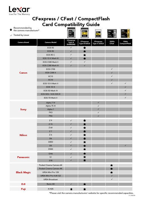
摄影相机卡片兼容性指南说明书
X-H2S
*Please visit the camera manufacturers’ website for specific recommended capacities.
P.1 2022/06
CFexpress Card Compatibility & Supported Video Format
Alpha 1FX3FX6Z9Z 7II
Z 6II
Z7
Z6
D6
D850
D5
D500
GH6
S1
S1R
Pocket Cinema Camera 6K
Pocket Cinema Camera 4K
URSA Mini Pro 12K
URSA Mini Pro 4.6K G2
URSA Broadcast
Ronin 4D
CFexpress / CFast / CompactFlash
Card Compatibility Guide
Recommended by the camera manufacturer*
Tested by Lexar
Camera Brand
Canon
Camera Model
EOS R3 EOS R5 EOS R5 C EOS 1D X Mark III EOS C500 Mark II EOS C300 Mark III EOS C700 EOS C300 II XC15 XC10 EOS 1D X Mark II EOS 1D X EOS 5D Mark IV EOS 5DS / EOS 5DS R EOS 7D Mark II
D6
GH6
S1 S1R Ronin 4D X-H2S Alpha 7 IV Alpha 7S III Alpha 1 FX3 FX6
CFAST6示例文档

CFAST简介一、CFAST概述CFAST是由美国国家标准和技术研究所(NIST)的火灾研究中心开发的火灾模拟软件,是继HAZARDⅠ和FASTLite之后应用在火灾危险计算上的第二代软件,现在的最新版本是CFAST6.0.10。
CFAST是一个多室火灾模拟程序,是根据质量守恒、动量守恒和能量守恒等基本物理定律建立的。
CFAST建立的火灾模型是建立在双区域模型理论基础之上的,着火房间被划分为两个控制体,即上部烟气层和下部的冷空气层。
CFAST6.0的运行界面如图2所示,菜单栏中有通常使用的“FILE”(文件),“RUN”(运行),“TOOL”(工具),“VIEW ”(查看)和“HELP”(帮助)五个菜单选项。
文件菜单栏用来新建、打开和保存文件,运行菜单中可对火灾进行模拟和打开可视化程序(smokeview)的模拟结果,工具菜单中可以打开可燃物和传热的介质的编辑界面,设置各种物理量的单位,查看菜单可以查看输入文件和输出文件,帮助菜单提供对用户使用说明。
该软件主要由simulation environment(环境参数模块)、compartment geometry(房间参数模块)、horizontal flow vents(水平通风模块)、vertical flow vents(垂直通风模块)、mechanical flow vents(机械排烟模块)、fire(火源设定模块)、detection/suppression(喷头及火灾探测器模块)、targets(目标物模块)、surface connection(房间交界面设定模块)等九个模块组成。
通过确定各个模块中需要设定的参数值,描述火灾发生前的场景,然后就可对火灾进行模拟。
模拟结果的所有输出文件都将与输入文件保存在同一个位置,通过文件菜单中的“SA VE”可将文件保存在设定的文档中,如果没有保存,在对火灾进行模拟时,软件会提醒你先将文件保存,然后才能进行模拟。
FastCAM套料操作流程
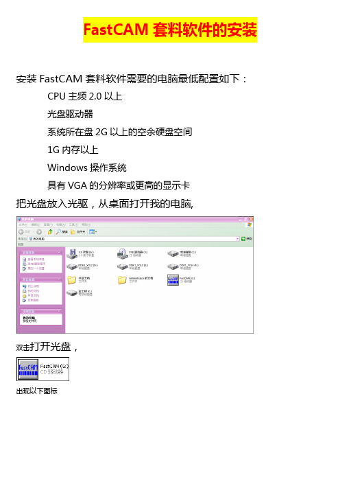
FastCAM套料软件的安装安装FastCAM套料软件需要的电脑最低配置如下:CPU主频2.0以上光盘驱动器系统所在盘2G以上的空余硬盘空间1G内存以上Windows操作系统具有VGA的分辨率或更高的显示卡把光盘放入光驱,从桌面打开我的电脑,双击打开光盘,出现以下图标点击将出现下面界面点击上面界面上的“简体中文”将出现下面界面点击上面界面上的“安装FastCAM”稍等将出现下面界面点击上面界面上的“Next”将出现下面界面点击上面界面上的“”后再点击“Next”将出现下面界面根据切割机控制厂家,在上面界面中选择相应的切割机控制器选项。
金属结构厂使用的设备应该选择“FastCNC”,然后在点击“Next”将出现下面界面点击上面界面中的“Install”将开始安装,稍等将出现下面界面点击上面界面中的“Finish”安装完成。
此时会出现如下提醒界面:如果后面出现错误提示,不用担心,那是因为还没有插加密狗:程序不完整产生的错误。
插上加密狗后再点击,稍等几分钟就安装完成了!退出点击左上角“HOME”然后按“ESC"即可提示:⑴安装演示文件请根据实际是否需要选择是否安装。
⑵安装路径只能在C盘,即:默认选项⑶下方的“FastCAM培训资料"可作为自学使用FastCAM套料软件的使用我们在FastCAM套料软件的长期使用中,认为以下介绍的方法为使用中最容易接受、最快速上手并能保证切割质量和板材利用率的使用方法。
其它方法请在以后的使用中参考FastCAM套料软件的说明书。
每次使用FastCAM套料软件前,请将加密狗插到电脑的USB接口上,等电脑上显示USB设备可用后。
在桌面打开文件名为“FastCAM”文件夹.如安装完桌面没有文件名为“FastCAM”文件夹,刷新桌面一次就会有了。
用AutoCAD画制1:1的图纸。
图中只画出需要切割的线条,其它如标注,画图时使用的一些辅助线等,请在图画好后及时删除。
- 1、下载文档前请自行甄别文档内容的完整性,平台不提供额外的编辑、内容补充、找答案等附加服务。
- 2、"仅部分预览"的文档,不可在线预览部分如存在完整性等问题,可反馈申请退款(可完整预览的文档不适用该条件!)。
- 3、如文档侵犯您的权益,请联系客服反馈,我们会尽快为您处理(人工客服工作时间:9:00-18:30)。
1 程序简介1.1起步1.1.1学习使用FAST1.2.2硬件及软件配置1.1.3安装1.2.软件概述及适用范围1.2.1火灾模型的实用性1.2.2火灾1.2.3羽流及Layers1.2.4出口风流1.2.5热传导1.2.6物种浓度与密度1.2.7软件使用假设与范围1.3什么是用户使用界面(GUI)?1.3.1使用鼠标及其它定点设备1.3.2 GUI的有关术语1.3.3GUI界面按钮及菜单项1.4启动FAST1.5FAST主菜单2 创建程序输入数据2.1创建一新输入文件——一实例2.2基本的火灾模型输入2.2.1输入输入文件的文件名2.2.2记录时间及电子表格输出2.2.3设置试验环境2.2.4定义若干空间结构2.2.5定义水平流之间的联系2.2.6定义竖直流之间的联系2.2.7增设水喷淋器和火灾探测器2.2.8定义火源2.2.9记录与时间相关的火灾实验曲线2.2.10工具集2.3高级火灾模型输入方法详解2.3.1建筑空气控制系统HV AC2.3.2HV AC系统通风口2.3.3HV AC系统内部连接与安装2.3.4HV AC系统通风管道2.3.5HV AC系统通风机2.3.6顶棚射流表面的选取2.3.7指定多个火源2.3.8顶棚到地板的热传导2.3.9定义目标层2.3.10确定单区或两区模型2.3.11选择运行时间图标类型2.4交互式数据库2.4.1选取默认材料2.4.2选取默认对象2.4.3创建变换的数据库2.4.4编辑热物理数据库2.4.5编辑对象数据库对象火灾曲线(61);对象备注(63);闪火传播对象属性(64)2.5修改配置文件2.6运行一个简单实例2.7新文件定义的标准过程2.8数据文件的打开和保存2.8.1选取一个已有的数据文件2.8.2创建一个新的输入数据文件2.8.3保存对数据文件的修改3.运行火灾模型3.1进行模拟3.2边模拟边运行3.3处理模拟过程中的事件3.4保存模拟出的模型4复杂模型实例4.1事件4.2计算机分析4.3输入数据4.3.1输入文件名4.3.2定义外部条件4.3.3指定模拟时间和电子表格的输出4.3.4改变火灾房间的几何形状4.3.5改变通风口4.3.6改变火源的定义4.3.7保存对数据文件的修改4.4运行模型4.5模型运行结果5预测软件包5.1逃生时间5.2喷淋器与探测器的动作5.3房间烟气温度5.4上浮的热气压头5.5顶棚射流温度5.6顶棚羽流温度5.7横向火焰传播5.8火灾严重性公式5.9通过开口的质量流5.10 羽流充填速率5.11辐射引燃5.12开口处的烟气流动5.13托马斯轰然公式5.14通风极限6 文件操作6.1改变路径6.2改变显示单位6.3设置色制和模式6.4输入数据的纠错6.5拷贝文件6.6打印文件6.7浏览文件6.8删除文件7 参考文献及附录文献信息FAST是一本有关火灾模型的使用工具手册,他参考了以前的火灾模型CFAST,并且增加了火灾形成过程,提供了在分隔空间构筑物中的火现象的工程计算。
这本使用手册提供了使用范例及相关的资料。
详细介绍了软件的安装方法及使用指南。
关键词计算机模型;计算机程序;排空;火灾模型;火灾研究;火险评价;人的行为;毒性。
订购信息美国NIST研究所FAST用户指南:预测火灾发展与烟气蔓延的工程工具建筑火灾研究实验室美国NIST研究所简单的代数方程是工程计算的基础。
1984年Bukowski提出了用一系列独立的火灾计算来评估一个复杂,交互的过程,即,火危险分析[ 1 ]。
在1985年,一系列适用于火灾评估的方程出版发行了。
尼尔森[ 3 ] 用FIREFORM 和FPE工具进一步扩展了这个概念,并且提供了一广泛地在火灾安全工程计算中被使用的软件包,这个软件包里提供了简单的工程计算模型。
1989年6月,NIST研究所的火灾研究中心(现BFRL的一下属机构)针对火灾对居民人身安全的危害,以及室内家具、电线等物品的火灾时的相关危害发布了一种定量分析的方法。
这种分析方法经过6年的深入研究,最终推出了第一代应用软件——HAZARD I。
它是世界上第一代火灾模拟综合应用软件,它结合了专家们的判断和计算的标准来评估一次特定火灾的后果。
FAST是建立在CFAST基础之上的一种程序集,他提供有关框架结构的火险工程评估。
他是继HAZARD I 和FASTLite之后的应用在火险计算上的第二代软件。
FAST包括了以前FIREFROM中的独立的工程计算,是CFAST(它包括了HAZARD I和FASTLite)的更新版本,他的用户界面与FASTLite相似。
本说明书提供了参考文献和应用实例,以及使用指南说明了软件的安装等操作。
首先,注意一点fast是针对火灾安全领域的专业人士设计的,并且是对他们决策的补充。
软件的目的是对火灾灾害结果提供定量分析,该模型只能在对计算的精确性进行证实性测试后,在其允许的误差范围内使用。
然而,正像许多其它计算机软件那样,软件使用者提供的输入数据直接决定了计算结果的准确性。
如果有模型得到的预测结果精确性较差,有可能导致错误的结论,所以又该模型得到的所有结果都应该凭一般经验进行审核。
1.1开始FAST是建筑火灾蔓延的预测工具。
这张光盘中包括该软件及相关文件,用户可按照说明书进行安装。
虽然该软件的安装及运行较简单,但是要想更有效的使用该软件的各项功能,用户必须阅读使用说明,建议浏览一下软件使用说明书的目录,熟悉该使用手册的内容。
1.1.1学习使用FAST为典型火灾案例的现实模拟量建立恰当的输入数据的过程是比较复杂的。
当用若干典型参数来描述现实模拟量时,几乎所有特定测试实例的数据都能被定制。
本使用说明中包括了所有的数据输入的详细描述。
这一节提供了一个可能的方案指导用户使用。
1.第5页的1.2节对FAST的理论基础及预测方程使用的限制条件进行了概述;2.从第14页开始,对用户界面中的每一项内容进行了详细的描述,如鼠标键盘的使用、数据输入界面及结果显示画面。
初学者有必要对本章进行学习以便熟悉图形用户界面的一些概念。
3.在第23页的第2节,介绍了一个单室火灾的简单范例,提供了运行该实例的具体步骤。
学习本范例后用户将熟悉软件的基础操作。
4.在第83页的第5节,讲述了许多预测工具,它们都包括在FAST软件中,能用来对个别的火灾现象进行描述。
这些工具需要两个以上的输入参数,大多数的程序只需要做相对较少的工作就可获得预测结果。
5.最后在第25页第2.2节,对FAST的数据输入进行了详细的描述,它可用来定制个别测试实例的数据。
1.1.2硬件及软件配置要求1.1.3软件安装安装向导提示了必要的信息并拷贝必要的文件到硬盘上。
FAST是基于DOS环境下的程序,应直接在DOS 环境下安装。
如有必要,在安装前可退出Windows环境及应用程序。
以下是安装步骤。
将安装光盘放入光驱,输入如下命令:D:INSTALL在安装的过程中有几个问题需要用户回答,可根据自己的需要做适当的回答。
一般都是取默认值。
在每一个安装画面中,安装向导都有相应的提示。
下面对安装步骤进行具体介绍。
将fast单独安装在一个目录中。
开始的两个安装画面显示了主程序的安装目录,一般缺省为c:,安装程序至少需要12兆直接的空间。
当程序拷贝时,安装向导将显示出安装进度。
为了能正确安装,安装组件可能需要创建或是移动DOS中的启动文件CONFIG.SYS中的语句FILES=,如果你要手动移动,你可以跳过这个步骤。
FILES=语句至少要为该软件指定50个文件。
1. 2概述与局限预测火灾趋势的分析模型从60年代就开始发展,经过30多年的发展与完善,模型已相当成熟。
起初,研究的重点是用数学语言描述火灾发展的三个阶段,即发展、蔓延、熄灭。
这种与实际分离较大的数学表达方式仅为安全性分析提供了火灾燃烧现象的一小方面特征。
根据多重的单个现象的组合可以编制出复杂的计算机程序,给出输入参数后,就可以预测出预计火灾发生的原因。
这些分析模型经过发展已可以给出最符合工程实际应用的火灾状态的预测。
当前国际上已有36种火灾模型,其中,20种是预测火灾发生的环境温度,19种预测烟气运动,6种计算火灾的发展速率,9种预测材料的耐火性,4种计算火灾探测器与水喷淋器的灵敏度,2种是计算火灾中人员疏散时间。
现在这些计算机模型在使用范围、复杂程度、使用目的等方面变化很大。
如单室火灾模拟程序ASET移植性很好,对于单个房间内的火灾可给出较好的预测。
有些模型为了特定的使用目的提供了单一的功能,如,COMPF2程序计算发生跳火的房间温度;LAVENT程序计算在一设有水平出口和风流减速帘的房间内顶棚射流的相互作用。
此外还有HARVARD 5 code 和FIRST用来预测单一房间内多个燃烧体的燃烧状态。
除了上面提到的单室火灾模拟程序外,还有一些多室火灾模拟程序,包括BRI,HARVARD 6 code,FAST,CCFM,CFAST 和FASTLite。
所有的火灾模型都可分为两类:一种是根据质量守恒,动量守恒和能量守恒等基本物理定律建立的;一种是根据实验做出曲线来找出个参数之间的关系。
这两类模型中都采用了数学近似及简化假设。
根据火灾的物理原理可建立数学表达式,再将得出的守恒方程式代入温度,烟气浓度等参数的预测方程,并输入计算机就可得到解决方案。
发生火灾的环境是不断变化的,所以这些方程通常为微分形式。
一个完整的方程组能计算出在一定时间内受限空间的火灾环境。
火灾模型假定在任何时候,控制体内的温度,烟气密度,组分浓度等参数都相同。
不同的火灾模型将建筑物划分为数目不同的控制体。
目前应用最广的一类火灾模型称为区域模型,通常它把房间分为两个控制体,即上部热烟气层与下部冷空气层。
在发生火灾的房间里,把火羽流或顶棚射流当作附加控制体可提高预测的准确性。
这种分层的方法来自对火灾实验的观察。
热烟气在顶棚聚集并从顶棚开始充满整个房间。
在实验中层中环境是不断变化的,而两层厚度的变化更大,所以区域模型在大多数火灾环境中可得到相当接近现实的模拟。
此外,还有网络模型和场模型。
前者把每一间房间看成一个节点来预测远离起火房间某地点的环境;而场模型则完全从另一个角度出发,它把一个房间划分为上千甚至是上百万个网格。
它们能够用来预测层内的环境变化,但是其运行时间大大超过区域模型,所以只在细节计算中使用。
1.2.1 火灾模型的适用性在FAST中使用的CFAST模型是用来计算火灾期间建筑物内的烟气及温度的分布。
CFAST是基于解状态参数方程组的基础上的,这些参数(压力,温度等)是基于在一微小时间间隔内的焓与质量变化之上的。
这些方程式根据能量守恒,质量守恒,动量守恒以及理想气体定律而得到的。
这些守恒方程式是绝对正确的,所以有火灾模型得到的错误结果只会是由方程的数学表达式及简单假设造成的。