DCP100数字程序控制器操作手册(英文)
IPS100使用手册

目录目录 (1)第一章前言 (3)第二章关于本产品 (4)关于IPS100 (4)本产品的使用环境 (4)包装内容 (4)各部件的名称和功能 (5)接口 (5)指示灯 (5)复位按键 (6)系统出厂配置 (6)第三章安装方法 (7)准备 (7)连接打印机 (7)连接网络线 (7)通电并检查指示灯 (7)管理员软件安装 (8)普通用户软件安装 (10)软件卸载 (12)第四章在Windows环境下进行网络打印 (13)在Windows 2000/XP 环境下用TCP/IP 协议打印 (13)确认PC的网络设置 (13)设置本产品 (14)搜索 (14)选择 (15)设置IP地址 (15)确认 (16)使用RAW方式进行打印 (17)使用LPR方式进行打印 (24)使用SMB方式进行打印 (28)使用IPP方式进行打印 (31)第五章使用打印服务器管理工具 (33)系统要求 (33)软件安装 (33)软件操作 (33)第六章使用打印机状态监视工具 (43)软件安装 (43)软件操作 (43)第七章使用WWW浏览器 (45)启用WWW浏览器 (45)常规 (46)设置 (48)信息 (52)第八章常见问题及故障维修 (55)第一章 前言感谢您购买本公司的网络打印服务器。
这本使用手册详细地记述了本产品的设置及使用方法。
为了正确使用本产品,请仔细阅读本手册并注意保管。
本产品是10BASE-T/100BASE-T 自适应打印服务器,主要以TCP/IP (WindowsXP,Windows2000)协议为基础,实现多种网络打印服务协议。
本手册将指导使用的顾客如何设置并使用本产品。
【使用本手册的注意事项】未经本公司的许可,本使用手册不得转载或复制。
一经发现,将追究法律责任。
今后本使用手册内容变更时不再预告。
本使用手册本着尽全尽善宗旨编辑。
对于所使用的设置实例结果,本公司不负责任。
有关本产品的问题请与芯彩科技联系,芯彩科技全程服务热线电话:010-8289-6060。
DP100说明书V1 JIATEN数显箱操作说明书

为了确保仪器正确安全的使用,在其出版的手册中使用了不同的安用户手册使用约定安全标志全标志(警告示语和安全警示标志),以便用于识别,防止危险并避免事故。
一般警示标志:表示存在潜在的危险,如果不注意,可能会造成轻度或中度的人身伤害或财产损失。
特殊警令标志:禁止特定的行动,左侧表示“禁止拆卸”。
特殊声明:本用户说明手册仅供用户参考,如果说明书中的说明文字与实物的操作方式存 在差异时,以实物的操作方式为准!本公司保留对该产品进行性能升级的权力,当公司对产品 进行升级时,恕不另行通知!。
DP100的所有解释权归嘉腾仪器仪表有限公司所有!注释类型本手册中使用下列类型的注释,帮助操作人员通过正确的使用仪器,获得可靠的测量数据。
重要● 一种重要的注释,是完成一项任务所必需的知识,如想顺利完成任务,不能忽 视这项注释。
● 一种提示您小心的注释,如不注意可能会造成数据丢失,降低精度,产生故障 或无法正常使用。
注意●这种注释是强调或补充主要文字内容的重要,它也是提供一些特殊的信息(例如存储器限制设备配置或特殊版本的软件说明)。
提示●提示是一种能帮助用户的注释,它根据用户的需求来帮助用户使用好本文所描述的技术和程序。
●它也提供了与论述主题相关的参考信息。
使用环境条件●避免暴露于烈日或高温下,使用温度必须在0~40 o C的范围内。
●远离高电压,大电流,强磁场的设备。
●光学尺信号电缆线尽量远离电源线。
●避免使用在铁屑,油,水,粉尘环境及安装在的振动较大的环境。
●远离强酸,强碱及化学药品。
使用说明● 如果发生故障,例如在电源开启的情况下,液晶显示屏无图像显示,应停止使用DP100 数显箱。
同时通知嘉腾仪器仪表公司立即派人修理。
在这种情况下,如果继续使用DP100 数显箱,将可能导致电击或火灾。
● 不要让异物,如水、金属或其它液体从后面的接口处进入DP100 数显箱,否则将可能导致电击或火灾。
● 不要损坏或改装AC电源适配器的电源线。
SDP100安装使用手册1.1
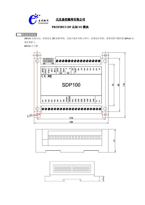
北京易控微网有限公司PROFIBUS DP从站IO模块SDP100安装方法:如果是有IEC标准导轨,直接卡装在导轨上即可。
如果没有导轨,需要用四个螺丝把SDP100安装在机柜上。
SDP100尺寸图参照下图接线端子说明接线:继电器输出的接线方法如下:开关量输入的接线方法如下:模拟量输入有两种接法如下: ⑴二线接法⑵三线接法⑴⑵通讯口的接线方法如下:MODBUS通讯接口PROFIBUS通讯接口POWER 为电源指示灯RUN 为运行灯运行为闪烁状态MB MODBUS指示灯通迅时为闪动DP PROFIBUS DP指示灯正常时为常亮,错误时为闪动MODBUS通讯口:当A和B涂掉为232通讯口,RXD和TXD涂掉为485通讯口PROFIBUS与MODBUS地址设置:PROFIBUS地址与MODBUS共用低五位的拨码开关,范围1-31; 拨码开关全都为ON的时候,默认 DP的地址为1,MODBUS的地址为1。
保持寄存器40041为软件PROFIBUS软件地址设置,当此寄存器范围为1~125时,此地址作为DP地址有效8位拨码开关选择本模块的地址(也就是MODBUS规约中的设备地址),拨码开关标有数字位“1”的为最低位,标有数字位“8”的位最高位,全部拨到ON的地址为“0”。
单元地址按照二进制表示,只使用最低的五位,高三位系统保留。
高位低位比如⑴:5ON 4ON 3OFF 2ON 1ON0 0 1 0 0 对应的单元地址为04高位低位⑵:5ON 4OFF 3OFF 2ON 1ON0 1 1 0 0 对应的单元地址为12SDP100端子图端子定义如下:DO1 第一路继电器输出端 DI1 第一路开关量输入端DO2 第二路继电器输出端 DI2 第二路开关量输入端DO3 第三路继电器输出端 DI3 第三路开关量输入端DO4 第四路继电器输出端 DI4 第四路开关量输入端DO5 第五路继电器输出端 DI5 第五路开关量输入端DO6 第六路继电器输出端 DI6 第六路开关量输入端DO7 第七路继电器输出端 DI7 第七路开关量输入端DO8 第八路继电器输出端 DI8 第八路开关量输入端DOCOM 继电器输出公共端 DICOM 开关量输入公共端AI1 第一路模拟量输入端AI2 第二路模拟量输入端AI3 第三路模拟量输入端AI4 第四路模拟量输入端AI5 第五路模拟量输入端AI6 第六路模拟量输入端AI7 第七路模拟量输入端AI8 第八路模拟量输入端AGND 模拟信号输入公共地PROFIBUS通讯口P PROFIBUS接口PB PROFIBUS接口NMODBUS通讯口A/RD RS232接收端/485A(正)B/TD RS232发送端/485B(负)GND RS232接口的GNDL/+5/12/24/48V 220V AC电源输入或直流电源输入正N/- 220V AC电源输入或直流电源输入负8路开关量输入对应地址为I6.0,I6.1,I6.2……依次类推8路开关量输出对应地址为Q7.0,Q7.1,Q7.2……依次类推8路模拟量输入(0-20mA或0-5V) 对应地址为PIW320,PIW322,PIW324……依次类推●继电器定义,功能码01/05序号地址数据描述01 00001 第一路继电器输出(DO1)02 00002 第二路继电器输出(DO2)03 00003 第三路继电器输出(DO3)04 00004 第四路继电器输出(DO4)05 00005 第五路继电器输出(DO5)06 00006 第六路继电器输出(DO6)07 00007 第七路继电器输出(DO7)08 00008 第八路继电器输出(DO8)09 00009 虚拟继电器直流1断线10 00010 虚拟继电器直流2断线11 00011 虚拟继电器直流3断线12 00012 虚拟继电器直流4断线13 00013 虚拟继电器直流5断线14 00014 虚拟继电器直流6断线15 00015 虚拟继电器直流7断线16 00016 虚拟继电器直流8断线●开关量输入定义,功能码02序号地址数据描述01 10001 第一路开关量输入(DI1)02 10002 第二路开关量输入(DI2)03 10003 第三路开关量输入(DI3)04 10004 第四路开关量输入(DI4)05 10005 第五路开关量输入(DI5)06 10006 第六路开关量输入(DI6)07 10007 第七路开关量输入(DI7)08 10008 第八路开关量输入(DI8)●输入寄存器定义,功能码04序号地址数据描述01 30001 第一路模拟量输入(AI1) 2000/5000为满度 0-20ma或0-5V02 30002 第二路模拟量输入(AI2) 2000/5000为满度 0-20ma或0-5V03 30003 第三路模拟量输入(AI3) 2000/5000为满度 0-20ma或0-5V04 30004 第四路模拟量输入(AI4) 2000/5000为满度 0-20ma或0-5V05 30005 第五路模拟量输入(AI5) 2000/5000为满度 0-20ma或0-5V06 30006 第六路模拟量输入(AI6) 2000/5000为满度 0-20ma或0-5V07 30007 第七路模拟量输入(AI7) 2000/5000为满度 0-20ma或0-5V08 30008 第八路模拟量输入(AI8) 2000/5000为满度 0-20ma或0-5V09 30009 机内电源电压 3300 表示3.3V10 30010 机内温度 400 表示40摄氏度11 30011 第一路开关量输入频率为闸门时间内所记下的脉冲个数12 30012 第二路开关量输入频率为闸门时间内所记下的脉冲个数13 30013 第三路开关量输入频率为闸门时间内所记下的脉冲个数14 30014 第四路开关量输入频率为闸门时间内所记下的脉冲个数15 30015 第五路开关量输入频率为闸门时间内所记下的脉冲个数16 30016 第六路开关量输入频率为闸门时间内所记下的脉冲个数17 30017 第七路开关量输入频率为闸门时间内所记下的脉冲个数18 30018 第八路开关量输入频率为闸门时间内所记下的脉冲个数 保持寄存器定义,功能码03/06序号地址数据描述01 40001 系统实际时间的低16位02 40002 系统实际时间的高16位03 40003 第一路开关量32位计数器低16位04 40004 第一路开关量32位计数器高16位05 40005 第二路开关量32位计数器低16位06 40006 第二路开关量32位计数器高16位07 40007 第三路开关量32位计数器低16位08 40008 第三路开关量32位计数器高16位09 40009 第四路开关量32位计数器低16位10 40010 第四路开关量32位计数器高16位11 40011 第五路开关量32位计数器高16位12 40012 第五路开关量32位计数器低16位13 40013 第六路开关量32位计数器高16位14 40014 第六路开关量32位计数器低16位15 40015 第七路开关量32位计数器低16位16 40016 第七路开关量32位计数器高16位17 40017 第八路开关量32位计数器低16位18 40018 第八路开关量32位计数器高16位19 40019 为串口1收发延时设置,16位,以1ms为单位20 40020 为串口2收发延时设置,16位,以1ms为单位21 40021 串口1波特率设置22 40022 串口2波特率设置40021~40022内容用16进制表示为 0XPQRS R保留8位数据位,1位停止位,P 高4位为奇偶校验设置。
PT-100充电控制器说明书

Model Numbers•PT-100 Available For•RenewableEnergy SystemsOff-grid PowerBack-up Power Works With•MS Series•MS-PAE Series•MMP Panel System•MP Panel System The PT-100 is a Maximum Power Point T racker (MPPT) charge controller designed to harvest the maximum available energy from the PV array and deliver it to the batteries. The PT-100’s MPPT algorithm finds the maximum power point of the array and operates at this point while regulating the output current and battery voltage to fully charge the battery.Features•High Efficiency: The PT-100provides higher than 99% conversionefficiency and uses less than two wattsof power in nighttime mode.•MPPT: Maximum Power PointT racking technology for increasedPV power output efficiency.•Voltage Options: Compatiblewith 12, 24, or 48V battery systemswith automatic detection ofsystem voltage.•Support a Large PV Array: A singlecontroller supports a large PV arrayup to 6600W.•Optimal Battery Charging:Automatic battery temperaturecompensation using an includedexternal temperature sensor foroptimum battery charging, evenduring extreme temperature changes.•Multi-state Charging:Maximizes system performanceand improves battery life.•GFDI: Integrated PV Ground-Fault Detection and Interruption/Indication, with pre-fault leakage/diagnostic metering.•Extensive Electronic Protection:Over-temperature protection, powerderating when temperature is high,PV short circuit and high PV inputshutdown, output overcurrentprotection and night-time back-feed(reverse current) protection.•LED Indicators and Screen:Multiple LED indicators and largedigital LED screen on front panel foreasy-to-read system information.•AFCI: An integrated PV Arc-FaultCircuit Interrupter detects, indicates,and extinguishes series arcs. The AFCIis designed to meet the new NationalElectric Code (NEC) Article 690.11requirements.•Convenient Installation: Run all ofthe wiring to the unique, remain-in-place wiring box with ease prior toinstalling the full PT-100 unit.•On-site Updates: The PT-100’ssoftware can be updated on site.•Easy MP and MMP integration:The PT-100 is designed to work witha Magnum Panel (MP) or Mini-Magnum Panel (MMP). It providesroom and access to PV and batterydisconnect breakers.Even More Functionality withthe Optional Remote•Built-in programmable auxiliary relayfor device control.•Internal data logging functionalitykeeps energy harvest information andbattery Ahr/Whr data up to 255 days.Use the optional remote to displaythis information.The World Depends on Sensors and Controls MAGNUM-DIMENSIONS2211 West Casino RoadEverett, Washington 98204 USA425-353-88334467 White Bear PkwySt. Paul, MN 55110 USA800-553-6418 PT-100 CHARGE CONTROLLER SPECIFICATIONSTesting for specifi cations at 25° C. Specifi cations subject to change without notice.August 2015 Rev C Part #64-0660Maximum PV input voltage (any condition)200 VDC + battery voltage or 240 VDC - whichever is lower Maximum PV operating voltage187 VDC Maximum PV array short circuit current100 ADC Nominal battery voltage range12, 24, or 48 VDC Battery charger output voltage range10 to 66 VDC Continuous charger output current100 ADC (from -20 °C to +40 °C) with proportional power reduction up to 60 °C ambient Maximum output power6600 watts Peak (and full power) efficiency>99% (98% typical)Tare loss / nighttime power consumption<2 watts (fan off, display/LEDs off)Charger regulation method Automatic three-stage (bulk, absorption, float) charge with manual equalizationBattery temperature compensation With Battery Temperature Sensor (BTS) connected (battery temperature -20 °C to +55 °C)Internal cooling Using dual ball-bearing fans for long lifeOvercurrent protection With two overlapping circuitsOver-temperature protection On transformer and MOSFETSListings ETL Listed to UL/cUL 1741, CSA C22.2 #107.1-01, CEWarranty Five years parts and laborOperating temperature -20° C to +60° C (-4° F to 140° F)Nonoperating temperature -40° C to +70° C (-40° F to 158° F)Operating humidity 0 to 95% RH non condensingEnclosure type Indoor, ventilated, with removable powder-coated conduit boxUnit dimensions (w x h x d)8.5” x 15.5” x 4.0” (21.6 cm x 39.4 cm x 10.2 cm)Shipping dimensions (w x h x d)11.5” x 19.5” x 8.125” (29.2 cm x 49.5 cm x 20.6 cm)Mounting Mounted on a vertical surface (wall) or installed on MP or MMP enclosureWeight 12.5 lb (5.7 kg)Shipping weight 15 lb (6.8 kg)Max operating altitude15,000’ (4570 m)。
DC系列伺服驱动器使用说明书

DC系列伺服驱动器使用说明书DC s e r i e s ser v o d r i v er u s e n g m a n u a l深圳市欧诺克科技有限公司DC 系列伺服驱动器型号说明备注: 1.驱动器供电电压必须大于或者等于电机额定电压2.驱动器的额定电流必须大于或者等于电机的额定电流DCPC-09012- OP E B系列DC/DE/DE2/BC/BC2/DH/BH制动单元B:带制动单元反馈E:光电增量式A/B 正交C:磁电增量式A/B 正交 A17:光电绝对值17bit C17:磁电绝对值17bit R:旋转变压器 H:数字霍尔 S:模拟量正余弦输入指令P:脉冲Hp:高速脉冲A:模拟量R:RS485 C:CANopen E:EtherCAT特殊功能OP:脉冲输出 OA:模拟量输出R:轮切 F:追剪 Z:攻丝机专用额定电流16:16Amps(11Arms) 50:50Amps(35Arms) 150:150Amps(105Arms)供电电压090:18-90VDC 180:18-180VDC 135:18-135VDC 220:220VAC 380:380VAC A:单相B:三相DC 系列驱动器规格汇总表驱动器型号供电电压连续电流 Amps(Arms) 峰值电流 Amps(Arms)6S 反馈类型外形尺寸重量DCPC-09002-OPE 2A (1.4A ) 6A (4.2A )133*90*32mm0.35kgDCPC-09004-OPE 4A (2.8A ) 8A (5.6A )DCPC-09008-OPE 8A (5.6A ) 24A (16A )DCPC-09016-OPE 16A (11A ) 48A (33A )DCPC-09024-OPE 24A (16A ) 50A (35A )DCPC-09030-OPE 30A (21A ) 60A (42A )167*100*35mm0.45kgDCPC-09040-OPE 40A (28A ) 80A (56A )DCPC-09050-OPE 50A (35A ) 100A (70A )DCPC-09075-OPE 75A (52A ) 150A (105A )200*114*59mm 1.10kg DCPC-090100-OPE 100A (70A ) 200A (140A )DCPC-090125-OPE 125A(88A)250A(177.5A)DCPC-090150-OPE 150A (105A ) 250A (175A )221*140*59mm 1.45kg DCPC-090200-OPE 200A (140A ) 300A (210A )221*140*90mm 1.8kg DCPC-090300-OPE 300A (210A ) 420A (294A )DCPC-090300-OPE(新) 300A (210A ) 420A (294A )265*140*90mm 2kg DCPC-18024-OPE 18~180VDC 24A (16A ) 50A (35A )167*100*35mm 0.45kg DCPC-18050-OPE 50A (35A ) 100A (70A )200*114*59mm 1.10kg 75A (52A ) 150A (105A )DCPC-18075-OPE 100A (70A ) 200A (140A )221*140*59mm 1.45kg DCPC-180100-OPE DCPC-135100-OPE 18~13518~90VDC增量式DC 系列外形尺寸图L L 1WHH 3H2H1W1H4 HW2H4 HW 3W4型号L L 1W W1W2W3W4H H1H2H3H4DC-2A~24A 14113432/ 4.5/15.5895118 4.5134DC-30A~50A 16716035/2-4.5/19.510051224-4.5160DC-75A100A 200190594-5.0/25/1146032.54-4.8190DC-100AF 200190594-5.0/25/1146032.54-4.8190DC-150A 221211595/25/1406045 4.8211DC-150AF 221211595/25/1406045 4.8211DC-200A 221211905/25/140///211DC-300A 221211905/25/140///211DC-300A (新)265255905/25/140///255DC 系列端子定义J3J1 J2 J3S1J4 J5J6 J75 4 3 2 11、产品简介:1. 1 概述DC系列可编程智能伺服驱动器是一款通用、高性能、直流供电、结构紧凑的全数字伺服驱动器。
ColorKey Mover Spot 100 用户手册说明书

Mover Spot 100CKU-5050USER MANUALIntroductionThank you for purchasing the ColorKey Mover Spot 100. Please read theseinstructions carefully before use. Operating this fixture according to these instructions is important to avoid any possible damage or accidents caused bymisuse.ØPacking listn1x Mover Spot 100n1x Power Cordn1x Mounting Bracketn User ManualSafetyCaution! Opening this unit voids warranty. Contact ColorKey for any service requests. Warning! To avoid electrical shock, be sure to disconnect power before any service or when moving or setting up the fixture.Caution! Avoid direct eye exposure with the fixture when on.ØThis fixture is for indoor use only.ØThis fixture must be installed a minimum distance of 5 meters (16’4”) away from any lighted objects.ØDo not install or operate this fixture near flammable materials.ØThis device must be installed, operated, and maintained by a qualified professional.ØDo not touch the fixture with bare hands during operation as the surface temperature of the fixture can exceed 60˚C (140˚F). Turn off power and wait 15 minutes for the fixture to cool before attempting to touch it.ØPlease check if the voltage is in accordance with the rated power before installing.ØDo not operate this fixture if the power cord has been damaged. Turn off fixture and replace with a power cord of similar rating.Display OperationØMENU: Access the menu/Scroll through menu optionsØOK: Open/Select the current menu optionØENTER: Select the current menu option and returnØUP: Scroll through menu selection or parameter increaseØDOWN: Scroll through menu selection or parameter decrease ØDMX: Lit when receiving DMX signalØERR: Lit when error has occurredMenu GuideSet Run Mode DMX Controlled by DMX AddressSound Selects Sound Active ModeRandom Selects Random Movement ModeAuto Selects Auto Program Mode DMX Address 1-512 Address for Run Mode DMX Channel Mode 14 Ch. Selects 14 Ch. ModeTop Lamp Temp 1-110 Selects Lamp Temp SoundRegulator +/- 6 Adjusts Sensitivity Inverted Pan on/off Selects Pan InversionMenu Dimmer0-255 Manual Dimmer ControlShutter/Strobe Manual Shutter/Strobe ControlPan Manual Pan ControlTilt Manual Tilt ControlPan-Tilt Speed Manual Pan/Tilt SpeedColor Manual Color SelectGobo 1 Manual Gobo 1 SelectGobo 2 Manual Gobo 2 SelectGobo 2 Rotate Manual Gobo 2 RotatePrism Manual Prism ControlFocus Manual Focus ControlPan Fine Manual Fine Pan ControlTilt Fine Manual Fine Tilt ControlReset Manual ResetSys Dmx Monitor Displays Channel DMX values System Errors Displays System Errors Advan Password Input For Tech Service OnlyEN Language Select For English or Chinese↑180° Screen Rotation Rotate Screen for HangingDMX Values 14 Channel Mode1 0-255 Dimmer2 0-3 On (w Ch. 1 On)4-251 Strobe (Slow to Fast)252-255 Full ON3 0-255 Pan4 0-255 Tilt5 0-255 Pan-Tilt Speed (Slow to Fast)6 0-2550-4 White5-9 Red10-14 Yellow15-19 Blue20-24 Green25-29 Orange30-34 Magenta35-39 Cyan40-44 Red/White45-49 Yellow/Red50-54 Blue/Yellow55-59 Green/Blue60-64 Orange/Green65-69 Magenta/Orange70-74 Cyan/Magenta75-79 White/Cyan80-255 Rotation CC (Slow to Fast)7 0-790-9 Open10-19 Gobo 120-29 Gobo 230-39 Gobo 340-49 Gobo 450-59 Gobo 560-69 Gobo 670-79 Gobo 785-255 80-129 Rotate Clockwise (Fast to Slow)130-134 Open135-220 Rotate CC (Slow to Fast)221-255221-225 Gobo 1226-230 Gobo 2231-235 Gobo 3236-240 Gobo 4241-245 Gobo 5246-250 Gobo 6251-255 Gobo 78 0-2550-9 Open10-19 Gobo 120-29 Gobo 230-39 Gobo 340-49 Gobo 450-59 Gobo 560-69 Gobo 670-79 Open80-129 Rotate Clockwise (Fast to Slow)130-134 Open226-230 Gobo Shake Slow to Fast231-255 Unknown9 0-2550-63 Position64-127 Clockwise (Slow to Fast)128-190 Clockwise (Fast to Slow)191-192 Stop193-255 CC (Slow to Fast)10 0-9 No Prism10-14 Prism Active15-255 Rotate (Slow to Fast)11 0-255 Focus12 0-255 Pan Fine13 0-255 Tilt Fine14 0-249 No Function250-255 Reset (Hold 5 Seconds)Master/Slave Mode OperationMaster/SlaveMaster/Slave mode allows you to connect multiple units together using one (1) unit to control others in a chain. When a fixture is set to ‘Master Mode,’ this unit will always act as a controlling unit until it is switched out of ‘Master Mode’. The Master unit will send out signal via DMX to Slave units which will react in synchronization. When a fixture is set into ‘Slave Mode’, this fixture will receive the Master signal. To avoid master signal and DMX signal interference, do not connect DMX when using Master/Slave mode. If using a DMX run longer than 60 meters and/or over 32 units, a signal amplifier may be required.TroubleshootingProblem SolutionsNo DMX control u Make sure that the DMX cable is properly connected u Make sure that the DMX controller is operationalu Check the DMX cable for tears or breaksu Make sure that the fixture is in DMX modeFixture does notrespond to soundu Make sure that the fixture is in Sound Active mode.Technical InformationPower Supply: AC100-240V; 50-60HzPower Consumption: 120WPower Connection: PowerCon In/OutLED: 1 x 80W LEDLED Type: WhiteColor Wheel: 7 colors plus open, Continuous scroll at variable speeds + Split ColorsGobo Wheel 1: Metal - 7 static gobos plus open and 6 rotating gobos plus openGobo Wheel 2: Glass - 6 rotating gobos plus openBeam Angle: 10˚Pan: 540°Tilt: 270°Focus: MotorizedPrism: 3-facet (rotating)DMX Mode: 14 channelsDMX: 3-pin XLR In/OutDisplay: Color LCD screenHeight: 16.65"Width: 12.68"Notice to consumer: ColorKey offers a 2-year limited warranty. Please visit our website at to register your product.Please note: As we continue to work towards improving our products and your experience as a user, we recommend that you check our website periodically for updates to user manuals and specifications at or you may contact us directly at ********************.。
DI ELL操作手册
按一次,进入或退出制冷/热泵模 式,(制冷还是热泵模式要依赖于 参数 CF31 的设定)
2.4 组合键功能
同时按下 3 秒以上,进入
+
参数编程状态
IC100CX(1592022500 完全版 SC 2010.07.30).doc
IC100CX(1592022500 完全版 SC 2010.07.30).doc
编码:1592022500
当上述功能允许但没有激活运行时, 该图标熄灭。
当进入“menu”菜单浏览时,该图标 点亮。
防冻电加热器/ 联合加热 / 锅炉功能的 继电器输出了,该图标点亮。
当进入融霜状态时,该图标点亮。 当处于两次融霜之间的延时启动计时 期间时,该图标闪烁。 水流开关报警激活时,此图标闪烁。 当水泵处于停转状态时,此图标闪烁 表示水流开关报警数字输入处于正确 的状态(因为水泵停转水流开关报警 动作是正常的状态,而不是报警)。
如果远程面板与控制器通讯有了问题(包括硬件 故障或者可靠性很糟糕的连接),那么在远程面 板的上行会显示“noL”字符 (英文 no link(未连 接)的缩写) .
4. 面板的显示信息
如果连接了远程面板,就必须通过控制器进行相 应的配置:
右上方(红色)数码管: 其显示内容可设置,见 参数 CF44 (PB1、PB2、PB4, 设定点(参数值) ①、工 作设定点(实际设定点如动态设定点、节能运行 设定点或系统运行在无储水罐功能下的设定点 等)、 变化的温差状态、系统运行状态②))。 右下方(黄色)数码管: 其显示内容可设置,见 参数 CF45 (PB1、PB2、PB3、PB4, 设定点(参数值) ①、工作设定点(实际设定点如动态设定点、节能 运行设定点或系统运行在无储水罐功能下的设定 点等)、 变化的温差状态、RTC 实时时钟、系统 运行状态②))。 注: ①当系统运行在制冷模式下时显示制冷设定点, 当系统运行在热泵模式下时显示热泵设定点,当 系统待机时显示 OFF 字符。 ②当系统工作在制冷模式下时显示 OnC ,当系统 工作在热泵模式下时显示 OnH,系统待机时显示 OFF 字符。 注意: 远程面板 VI610 与 IC100CX 系列不兼容,请勿将 VI610 与 IC100CX 连接起来。
KP-100数字密码锁操作指南说明书

1MODEL KP-100ACCESS CONTROL DIGITAL KEYPADOPERATING INSTRUCTIONSAlarm Controls19 Brandywine DriveDeer Park, New York 11729(800) 645-5538Model KP-100 is a self-contained digital keypad. Thiskeypad is suitable for residential, industrial, and commercialinstallations. It is compatible with all electric locking devices.1. Pass the wire harness through the opening in the back box.2. Mount the back box to the door frame or wall.3. Make all required wiring connections to the terminal blocks.4. Place the keypad faceplate on the back box and secure with the screwsprovided.Power Input (12-24V AC/DC) 12 or 24 AC or DC. AC power can be connected without observing polarity requirement. Connect DC power with polarity as indicated.Output Relay SPDT dry contacts. Output can be programmed for latching or momentary operation.Egress Input (EG IN) A normally-open request to exit station can be connected to this terminal and ground (-). Connecting the terminal to ground will operate the output in the same manner as a valid user code.Tamper Contact Normally-closed output pair activated by the tamper switch if the keypad faceplate is removed from the back box.WIRINGON/OFFDAP JUMPER2Keypad initiation must be done at the initial turn-on of the keypad.1. Connect power to the keypad.2. Put the keypad in Program Mode by entering “0 0 0 0 ”. The keypad willbeep twice and the yellow LED will be on and not blinking.3. Enter “8 9 0 1 #”.4. The keypad will beep twice and the keypad initiation is complete.5. Enter “ ” to exit Program Mode. The yellow LED will begin blinking.It is strongly recommended that the Installer Code be changed from the default “0 0 0 0”. If the Installer Code is not known, please refer to the section on Direct Access to Programming.1. Put the keypad in Program Mode by entering “0 0 0 0 ” or the currentinstaller code. The keypad will beep twice and the yellow LED will be on and not blinking.2. Enter “0 (4 to 8 digit new installer code) #”. For example, to change theInstaller Code to 1 2 3 4 you would enter “0 1 2 3 4 #”.3. The keypad will beep twice indicating that the new Installer Code has beenaccepted.4. Enter “ ” to exit Program Mode. The yellow LED will begin blinking.It is necessary to put the keypad in Programming Mode in order to access all keypad configuration settings.1. Put the keypad in Program Mode by entering the Installer Code followed bythe “ ”. The keypad will beep twice and the yellow LED will be on and not blinking.2. Enter “ ” to exit Program Mode. The yellow LED will begin blinking.User Codes are 4 to 8 digits long and must not be the same as the Installer Code. The keypad can store up to 100 User Codes.Each User Code has a Code Number. Code Numbers are two digits ranging from “00” to “99”.1. Put the keypad in Program Mode by entering the Installer Code followed bythe “ ”. The keypad will beep twice and the yellow LED will be on and not blinking.2. Enter “(1)(Code Number) (User Code) #”.For example, if you wish to assign a User Code of “6 7 8 9” to Code Number “01”, you would enter “1 0 1 6 7 8 9 #”.3. Enter “ ” to exit Program Mode. The yellow LED will begin blinking.3Enter a valid User Code to activate the Output Relay. The keypad must be in standby mode (yellow LED blinking).1. Enter “(User Code) #”.For example, if the User Code is “1234” you would enter “1 2 3 4 #”.1. Put the keypad in Program Mode by entering the Installer Code followed bythe “ ”. The keypad will beep twice and the yellow LED will be on and not blinking.2. Enter “(1)(Code Number) #”.For example, if you wish to delete the User Code in Code Number “02” you would enter “1 0 2 #”.3. Enter “ ” to exit Program Mode. The yellow LED will begin blinking.To delete all User Codes enter “8 9 0 1 #”.The Outputs Relay can be programmed for either momentary or latching operation. Momentary operation time can be set for between 1 and 999 seconds. The factory default momentary operation time is 2 seconds.1. Put the keypad in Program Mode by entering the Installer Code followed bythe “ ”. The keypad will beep twice and the yellow LED will be on and not blinking.2. Momentary Mode -Enter “4 0 (output active time 1-999) #”Latching Mode -Enter “4 1 #”3. Enter “ ” to exit Program Mode. The yellow LED will begin blinking.The keypad beeper can be silenced.1. Put the keypad in Program Mode by entering the Installer Code followed bythe “ ”. The keypad will beep twice and the yellow LED will be on and not blinking.2. Enter “8 3 0 #”.3. Enter “ ” to exit Program Mode. The yellow LED will begin blinking.To return the keypad to audible mode -1. Put the keypad in Program Mode by entering the Installer Code followed bythe “ ”. The keypad will beep twice and the yellow LED will be on and not blinking.2. Enter “8 3 1 #”.3. Enter “ ” to exit Program Mode. The yellow LED will begin blinking.4When the keypad is programmed for Auto Entry Mode it is not necessary to terminate User Codes with the “#” during operation. However, in Auto Entry Mode the User Code must be the same length (4 to 8 digits) as the Installer Code.To put the keypad in Auto Entry Mode -1. Put the keypad in Program Mode by entering the Installer Code followed bythe “ ”. The keypad will beep twice and the yellow LED will be on and not blinking.2. Enter “8 2 1 #”.3. Enter “ ” to exit Program Mode. The yellow LED will begin blinking.To return the keypad to Manual Entry Mode -1. Put the keypad in Program Mode by entering the Installer Code followed bythe “ ”. The keypad will beep twice and the yellow LED will be on and not blinking.2. Enter “8 2 0 #”.3. Enter “ ” to exit Program Mode. The yellow LED will begin blinking.The keypad can be programmed to notify the user when the Output Relay is energized or the egress button has been pressed.To put the keypad in Output Annunciator Mode -1. Put the keypad in Program Mode by entering the Installer Code followed bythe “ ”. The keypad will beep twice and the yellow LED will be on and not blinking.2. Enter “8 1 1 #”.3. Enter “ ” to exit Program Mode. The yellow LED will begin blinking.To take the keypad out of Output Annunciator Mode -1. Put the keypad in Program Mode by entering the Installer Code followed bythe “ ”. The keypad will beep twice and the yellow LED will be on and not blinking.2. Enter “8 1 0 #”.3. Enter “ ” to exit Program Mode. The yellow LED will begin blinking.56If the Installer Code is forgotten, the Direct Access to Programming (DAP) utility can be used to put the keypad in Programming Mode .1. Disconnect the power supply from the keypad.2. Move the DAP jumper from the OFF to the ON position.3. Reconnect the power supply to the keypad (keypad will start beeping).4. Move the DAP jumper from the ON to the OFF position (keypad will stopbeeping and the yellow LED will be on and not blinking. The keypad is now in Programming Mode .5. A new Installer Code must now be entered.6. Enter “0 (4 to 8 digit new installer code) #”. For example, if you wish to change the Installer Code to 1 2 3 4 you would enter “0 1 2 3 4 #”.7. The keypad will beep twice indicating that the new Installer Code has been accepted.8. Enter “ ” to exit Program Mode . The yellow LED will begin blinking. The Green LED is on while Output Relay is activated.The Red LED is on while keypad is in Lockout Mode.The Yellow LED is described in the table below -Yellow LED Keypad Status Tone IndicatorOn Programming Mode None 1 Blink Successful Key Press 1 Beep2 Blinks Successful Code Entry 2 Beeps5 Blinks Error in Code Entry 5 BeepsContinuous Blinking Standby Mode NoneContinuous Blinking DAP Jumper not replaced Continuous ToneThe keypad can be temporarily disabled to prevent unauthorized access by entering a user specified 4 to 8 digit Lockout Code . The red LED will light when the keypad is in Lockout Mode. The keypad can be taken out of Lockout Mode by entering the Lockout Code again.1. Put the keypad in Program Mode by entering the Installer Code followed by the “ ”. The keypad will beep twice and the yellow LED will be on and not blinking.2. Enter “5 1 #”3. Enter “2 1 (Lockout Code) #”.For example, if you wish to assign a Lockout Code of “6 7 8 9”, you would enter “2 1 6 7 8 9 #”.3. Enter “ ” to exit Program Mode. The red LED will illuminate.Use N/C contact for magnetic locks and fail-safe electric strikes.Use N/O contact for fail-secure electric strikes.The 1N4004 Diode must be used for DC powered electric strike applications.TAMPER SWITCHThe Tamper Switch is Normally-closed when the keypad face plate is securely attached to the back box. Connect these terminals to an alarm panel if desired.CODESIt is recommended that the Installer Code and User Codes be noted here for reference. Installer CodeUser Code _______User Code _______User Code _______User Code _______User Code _______User Code _______User Code _______User Code _______User Code _______User Code _______User Code _______User Code _______7Operating Voltage 12 or 24 Volts AC or DC Auto-sensingActive Current Draw 50 mA maximum @12VDC 65 mA maximum @24VDCIdle Current Draw 9 mA maximum @12VDC 17 mA maximum @24VDCOutput Relay Contact Rating 10A@28VDCOutput Contact Arrangement Single Pole Double ThrowDimensions 2.875”W x 4.5”L x 1.375”DKP-100 Rev. B 5/148。
DCY100使用说明书正文
1概述1.1简介DCY100配料控制器设计用于各种配料系统,实现高精度配料显示和自动控制。
控制器采用先进的微控制器芯片以及高精度的模数转换芯片等集成电路,应用先进的软件和硬件设计技术,以优良的加工工艺确保产品的高性能和高可靠。
1.2特点♦双显示器同时显示毛重和净重。
♦集重量显示与配料控制为一体。
♦提供完整的配料控制功能,可控制12种不同种类的物料。
♦配料数据可通过面板按键或通讯口输入,并存储于存储器内。
♦预置配料数据具有断电保持功能。
♦自动零位跟踪。
♦按键自动去皮重。
♦软件全数字调校功能。
♦可选RS232或RS485为串行输入输出口,RS485可实现多点通讯。
♦串行通讯口输出配料数据、输入配料控制数据以及系统功能参数。
♦模拟量采集数据输出速率可达100次/秒。
♦显示分辨率最高达1/15000。
♦可设定通电时自动显示为零。
♦具有双重数字滤波,确保显示数据稳定。
♦去皮检测次数可设定以免不稳定的情况下造成去皮错误。
♦具有皮重超范围报警功能。
♦慢速配料控制可以设定延迟时间。
♦控制比较次数可设定确保控制不因秤体受到冲击而造成错误。
♦快速及慢速配料的禁止比较时间可单独设置。
♦可设定配料净重显示保持功能。
♦超差检测并输出告警信息。
♦可设定过冲量范围确保自动补偿功能不因机械故障而造成错误。
♦超差可以选择:不处理、手动处理、自动处理。
♦配料量超出宽容度时,可选进行“添量”或“减量”处理。
♦卸料控制功能。
♦可以单独进行零位、称量间距校准操作。
2技术规格2.1一般规格♦电源:交流220V(+10%,-15%),50Hz±2% ,内置电源滤波。
♦工作温度:0℃~40℃。
♦工作湿度:相对湿度≤85%RH(无凝露)。
♦电源功耗:6W。
2.2数字部分♦重量显示:双排数码管毛重、净重双显示,最左边显示“-”号。
♦超载显示:显示“”。
♦显示分度间距:1、2、5。
♦小数点位置:可选择4个不同位置。
♦输出容量:开集电极输出,最高50V,0.3A。
Frese ELCO 100 PID 控制器说明书
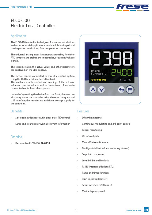
Electric Local ControllerFeatures• 96 × 96 mm format• Continuous modulating and 2/3 point control •Sensor monitoring • Up to 5 outputs • Manual/automatic mode• Configurable limit value monitoring (alarms)• Setpoint changeover • Level inhibit and key lock • RS485 interface (Modbus RTU)• Ramp and timer function • Push-in controller insert • Setup interface (USB Mini-B)•Marine type approvalApplicationThe ELCO-100 controller is designed for marine installations and other industrial applications - such as lubricating oil and cooling water installations, flow temperature control etc.The universal analog input is user programmable, for either RTD temperature probes, thermocouples, or current/voltage signals.The setpoint value, the actual value, and other parameters are displayed on the LED displays.The device can be connected to a central control system using the RS485 serial interface (Modbus).This enables remote control and reading of the setpoint value and process value as well as transmission of alarms to to a central control and alarm system.Instead of operating the device from the front, the user can also programme the controller using the setup program and USB interface; this requires no additional voltage supply for the controller.Benefits• Self-optimisation (autotuning) for exact PID control •Large and clear display with all relevant informationOrdering•Part number ELCO-100: 58-8958Electric Local ControllerFunctional descriptionSelf-optimisation (autotuning)Standard features include the tried and tested self-optimization (oscillation method), which makes it possible for the controller to be matched to the control loop by a user who is not a control technology expert.Here,the reaction of the control path to the specific variable changes is evaluated and the controller parameters proportional band, reset time, derivative time, cycle time, and filter time constant are calculated.Ramp functionThe ramp function is used for a constant change of setpointvalue w up to the ramp limit value SP (entered setpointvalue).A rising or a falling edge arises depending on the actualvalue at the time of ramp start t0.The slope is defined by a gradient which is entered duringthe controller configuration.Limit value monitoringThe controller is equipped with two limit value monitoring functions, each with eight configurable alarm functions. Any analog signals can be selected as actual and setpoint value froma selector. When a limit value is exceeded, a signal can be displayed or an internal controller function initiated. With the limit value monitoring, extensive alarm and limit value functions can be implemented.TimerThe timer is started manually or automatically (after power on, for example). When the timer expires, the timer output signal changes its state (configurable). The timer can be used to implement functions like time-limited control or setpoint changeover.Setup programThe setup program provides the user with an easy and comfortable way to configure the controller using a PC.The PC has to be connected to the controllers USB interface (Mini-B type) with a USB cable.Thereby the controller is powered over the USB interface. As a result, no mains supply is required during the configuration.Electric Local ControllerTechnical data ∙ ELCO-100 ControllerPower consumption: Max. 6.6 WVoltage Supply:AC 110 to 240V, +10/-15 %, 48 to 63HzMeasuring accuracy:≤ 0.1 % of measuring rangeAmbient temperature:-10 °C to 55°CStorage temperature:-30°C to 70°CWeight:220 gProtection class:Acc. to DIN EN 60529 , Front IP65/Rear IP20Dimensions:See drawing next pageOperating position:Any positionL,J,U,T,K,E,N,S,R,B,C,D,A1,L,KAnalog Input:ThermocouplePt100/Pt1000/KTYRTDResistance / Potentiometer (0 to 4000Ω)0(2) to 10V (500kΩ input resistance)0(4) to 20mA (< 2.5V burden voltage)Digital Input:Potential-free contactAnalog Output:0(2)(>500Ωload)10Vto0(4) to 20 mA (<450Ω load)Digital Outputs:Relays (N/O contacts) [Max 3A at AC230V or DC30V, resistive load]Logic output 0/14V (Max output current 20mA)RS485 interface:Modbus RTU (Galvanic isolated)controllerController type:Continousmodulating2/3 point controllerDisplay:Two 18-segment LCD display + Pixel matrix LCD for textUpper display: 25mm Color: White / Lower display: 12mm Color: Green Electrical connection:On the back via spring-cage terminalsApproval: c UL us (UL 61010-1 (3. Ed.), CAN/CSA-22.2 No. 61010-1 (3. Ed.))DNV GL (DNVGL-CG-0339)Alarm:Limit value in relation to setpoint valueFixed limit valueElectric Local ControllerDimensionsDisplay and control elements1. 18-segment LCD display (e.g. actual value), 4-digit2. 18-segment LCD display (e.g. setpoint value), parameters,values and text); display ”OK” when exiting editing mode (with change)3. Activity display for ramp function/program, timer, manualmode4. For type ELCO-100: pixel matrix LCD display for displaying menuitems, parameters and values as well as customer-specific text 5. Switching of the digital outputs (yellow = active)6. Up (in the menu: increase value, select previous menu item orparameter; in basic status: increase setpoint value)7. Down (in menu: reduce value, select next menu item orparameter; in basic status: reduce setpoint value)8. Back (in menu: back to previous menu level, exit editing modewithout change; in basic status: configurable function)9. Menu/OK (call up main menu, switch to submenu/level, switchto editing mode, exit editing mode with change)Electric Local ControllerTechnical dataConnection diagramThe connection diagram in this Technote provides preliminary information about the connection possibilities.For the electrical connection use the operating manual delivered with the product.The knowledge and the correct technical execution of the safety information/instructions contained in these documents are mandatory for installation, electrical connection, and startup as well as for safety during operation.The terminal strips on the device rear are equipped with screw terminals. Please refer to the technical data for specifications concerning the conductor cross section.(1)(2)(3)(4)Electric Local ControllerApplication temperature sensorScrew-in RTD temperature probe for marine applications.Temperature Range from -50 to +400 °CThe RTD temperature probes for standard and marine applications is commonly used for measuring temperatures in liquids and gases in pipes and tanks.Application areas:• Ballast water management • Water treatment systems• Generators, motors, and compressors • Heating and air-conditioning industry • For nearly all applications on shipsBenefits• Quick response times – a reduced probe tip allows response times of t0.9 = 14 s to be reached in water • Increased safety – thanks to successful testing by Bureau Veritas•Flexible and time-saving startup – due to availability of different standardized process connections Features• The connection head is suitable for ambient temperatures up to 100 °C.• Normally fitted with a Pt100 temperature sensor according to DIN EN 60751, Class B in 4-wire circuit connections.•The intelligent design of the RTD temperature probe with a fixed measuring insert allows temperatures to be measured under standard conditions.• Versions of class A or AA are also possible.• Versions with a reduced probe tip are available for quicker response times.• A transmitter can be integrated into the terminal head as an option.•The RTD temperature probes are certified according to Bureau Veritas.Electric Local ControllerTechnical data ∙ RTD temperature sensorTerminal head Form B DIN EN 50446, die-cast aluminum, M20 × 1.5Seal IP65Measuring insert Pt100 temperature sensor DIN EN 60751, cl. B, 4-wire circuit, permanently installed Response times t0.5 = 5 s, t0.9 = 14 s in water 0.4 m/s; ø6 mm Transmitter Accessories Programmable transmitter, output 4 to 20 mA or 20 to 4 mA Operating temperature -50°C to +400°C Measuring insert Protection pocket,Tolerance class Class B (Standard) Class A & AA (Optional)Protection tube Stainless steel 1.4571 (316Ti) in ø6 mm Process connection Screw connection G 1/2 B Environmental influences Admissible temperature at connection head -40°C to +100°C -40°C to +85°C (with transmitter)Permissible torque moment: 130 Nm Permissible flow velocities: Air: 25 m/s Hot steam: 25 m/s Water: 3 m/s Reaction times at liquid velocity = 0.4 m/sec: t 1/2: 5 s t 9/10: 14 s (t = total temperature step) Max. pressure: 165 bar Max. temperature: 400 °C Weight:280 gApprovals/approval marksElectric Local ControllerF rese A/S assumes no responsibility for errors, if any, in catalogues, brochures, and other printed matter. F rese A/S reserves the right to modify its products without prior notice, including already ordered products, if this does not alter existing specifications. All registered trademarks in this material are the property of Frese A/S. All rights reserved.Frese A/STel: +45 58 56 00 00*************Types and Operation DataDimensionsFitting length L: See table below Diameter probe D: ø6 mm Connection thread G:G 1/2 B。
C100__操作说明中文版__说明书

Model C100SmartBob Console操作说明安装和操作之前请仔细阅读.Division of Garner Industries7201 North 98th StreetLincoln, NE 685079741(402) 4349102目录安全摘要 (3)1.0介绍 (4)2.0 说明 (4)3.0 安装 (6)ٛ 3.1 安装 (6)ٛ 3.2 连接与接线........................................................................................................... .. (7)3.3 RS485 网络要求................................................................................................. .. (11)ٛ 3.4 防雷法/过载保护............................................................. ................................... .. (12)ٛ 3.5 布线图...................................................................................................... ... ... ... (13)4.0 操作. ... ... .. (14)ٛ 4.1 按键 (14)ٛ 4.2 菜单系统 (14)5.0 固件更新 (21)ٛ 5.1 更新要求....... ....... ....... . (21)ٛ 5.2 Atmel’s FLIP的下载与安装和JAVA运行环境 (21)ٛ 5.3 更新过程 (22)6.0 质保和服务 (23)ٛ 6.1 有限保修 (23)ٛ 6.2 技术支持,客户服务和修理r (23)7.0处理 (23)安全摘要为避免受伤和损坏设备,请看以下安全防护措施.产品必须由有资格的权威的个人来安装维护、.根据安装说明书来安装,且要符合所有国家和当地的有关规定.应用中用的电线是有额定电压和电流来额定的.在正常运行中要确保外壳盖子是紧紧牢固的盖着的.在潮湿的环境中要确保所有电气入口密封良好.如果该产品在某种程度上不是用在生产商指定的,那安全保护可能被损害.安全术语和标志警告:警告是鉴别会导致受伤和危及生命的情况发生,电击危险.小心: 小心是指示会导致产品或其它财产的损坏的情况发生.FCC 承诺注意: 本产品经过测试符合FCC规定第15部分中A级数码产品要求.符合这些要求的产品在商业环境下进行操作时能够提供合理防护并防止有害干扰.本设备产生,使用并发射无线电波,如果不按照使用手册进行安装或使用,可能对无线通讯造成干扰.在居民区使用本设备可能会造成有害的干扰在此情况下,用户需要自费排除干。
控制器英文说明书(英文面板)
CNC-220S User Manual VER. C-220 0266 /0268/0288/0399/ect.DOC NO:020129 Page1of 18迈维自動化有限公司maiwei AUTOMATION CO.,LTD.CONTENTS1. INTRODUCTION (2)2. MAIN FEATURES (2)3. FRONT PANEL DESCRIPTION (3)4. PROGRAMMING WINGING PARAMETER (5)5. WINDING METHOD DESCRIPTION (6)6. WINDING EXECUTION (8)7. CONFIGURATION SETTING (9)8. INSTALLATION AND WIRING (11)9. ADJUSTMENT (14)10. MAINTAIN AND TROUBLESHOOTING (15)迈维自動化有限公司maiwei AUTOMATION CO.,LTD.1. INTRODUCTIONCNC-220S is a series of COIL WINDING MACHINE CONTROLLERdeveloped by MAIWEI AUTOMATION . It not only retains all the features ofprevious designs, it also has a low noise level and is less sensitive to externalpower fluctuation.CNC-220S also features an integrated design: putting stepper motor driver,DC motor speed controller, brake and power supplier control circuits into onecontrol box, simultaneously achieving size reduction, high performance andlow cost.CNC-220S Series offers CNC-220S “Standard Model” and CNC -220S EXD"External Connection Model”, depending on whether a close -loop driver isprovided for various applications.2. MAIN FEATURES◆ Single chip DSP Microprocessor design, has further higher performance and higher functions; it also has less sensitive to external power fluctuation orto external electromagnetic interference.◆ Memory capacity capable storing up to 0- 1000 steps winding data, 9 winding parameters, and 5 options can be independentlyassigned for each step. Off-power memory retention without battery.◆ Winding speed can be specified using the front panel keypad, resulting ineasy programming of multi-step, multi-speed settings.◆ Guiding traverse shaft stepper motor with a constant-current driver offeringfast wire guiding speeds.◆ Power input AC100V~120V 、220V~240V 600VA(max).迈维自動化有限公司maiwei AUTOMATION CO.,LTD.3. FRONT PANEL DESCRIPTION3.1. Power switchPower:Power supplier equipped, controls the AC power to the controller.3.2. Key pads0-9:10 key, for entering numerical values.『QTY SET』:Enter into EDIT mode.『EDIT』:Specify target production quantity.『START STEP』:Specify starting step in memory.『END STEP』:Specify ending step in memory.『DATA SEL』:Select parameter to be programmed, or to switch display mode. 『FEED DIR』:Select guiding direction for each step.『WIND DIR』:Select winding direction for each step.『EDGE STOP』:To specify whether to suspend winding when the guiding traverse moves to the two edges of the width.『AUTO HOME』:Select whether to have auto-positioning function for each step. 『AUTO START』:Select whether to have auto-starting function for each step. 『-』:Reduce step number by one, or reduce PIECE COUNTER by one.『CLR』:During programming, clear current data to zero.『COPY』:Copy the data of previous step into current step.『ENT』:Write data into memory.『RPM』:Switch display to shows PIECE COUNT or RPM.『ZERO』:Hold down this key for two seconds to reset PIECE COUNTER to zero. 『AUTO』:To switch between AUTO and NON-AUTO mode.『BRAKE』:Switch whether brake will be applied to the win spindle during stopping.迈维自動化有限公司maiwei AUTOMATION CO.,LTD.『NEXT』:Skip current step and go to the next step.『PREV IOUS』:Discard current step and go to the previous step『RESET』:At any time, discontinues current operation and return to ready mode. 『STOP』:Pause during winding.『START』:Restart during pause, or pause during winding.←:guiding traverse moves to the left.→:guiding traverse moves to the right.:Show the current step number being wound or beingprogrammed.:During programming, in combination with LED, shows the parameter being programmed. During winding or ready mode, show thecurrent number of turns or show the guiding traverse shafts position.Shows PIECE COUNT or RPM.3.4. Status indicators□READY: lit means in READY mode, flash means PAUSE mode ,not litmeans winding or programming in progress.□RUN: lit means winding in progress; not lit means not in progress.□SLOW: during winding, lit means low speed winding; not lit means high speed winding.□MOVE: lit means guiding traverse is fixing the starting position forwinding or is returning to the home position.□O.S: lit means winding operation is over speeding, guiding traverseand winding spindle shaft are out of synchronization.□LAN: lit means currently communicating with network.□FINISH: will lit when reaching the preset piece count.□ RPM: lit means the PIECE COUNT DISPLAY shows RPM.□ QTY: lit means the PIECE COUNT DISPLAY shows the piece count.3.5. Winding parameters definitions□SHIFT : Starting position of the guiding traverse.[Setting range 0.00~ 999.99 mm].□WIDTH : The traverse of the copper wire led by the traverse duringwinding. [Setting range 0 ~999.99 mm].□PITCH : Diameter of the copper wire. [Setting range 0~ 9.999mm].□TURNS: Total number of turns to be wound.[Setting range 0.0~9999.9 or 0~99999 turns].□S.SLOW : Number of turns to be wound at low speed, when start winding.[Setting range 0~999.9 turns].□E.SLOW : Number of turns to be done at low speed prior to stopping.[Setting range 0 ~999.9 turns].□H.S.: High winding speed. [Setting range from 0~99%].□L.S. : Low winding speed. [Setting range from 0~25%].□FUN : Winding complete output signal setting.4. PROGRAMMING WINGING PARAMETER4.1. MEMORY RANGE SELECTIONCNC-220S contains 1000 memory step, By defining the region, users caneffectively manage the memory. Various winding parameter can be stored indifferent regions and can be retrieved instantaneously. After specifying theregions, programming and winding can be done in those regions; allun-selected regions will retain their original contents and unmodified. Whensetting the STEP number, the Ending step number must be larger than theStarting step number, or the winding operation will not startSpecifying starting stepIn ready mode, press to select. [Setting range 0 ~ 999].Specifying ending stepIn ready mode, press to select. [Setting range 0 ~ 999].4.2. Programming winding parameterIn “READY” mode, press invokes the programming mode. First the“START STEP” number will shows at “Procedures displayer”, the parameter indicator 『SHIFT』will lit, the starting position will shows at “Documents dispayer”. The starting position can be changed to the new position by pressing thenumerical keys followed by the key.After that the STEP number will automatically increase by one, to continue setthe starting position for next step. When the STEP number larger then the“END STEP”number, the STEP number will restore to the “START STEP”number and the indicator light will change from『SHIFT』to 『WIDTH』foruser to specifying the width for each STEP. Repeat the same procedure using numerical keys and the key, all winding parameters for each STEP canThe following functions are also available::To select guiding direction, forward or reverse.:To select winding direction, clockwise or counter-clockwise.:To specify whether to suspend winding when the guiding traversemoves to the two edges of the width.:To select whether guiding traverse returns to the starting positionautomatically or upon a manual pressing of the key.:Select whether to have auto-starting function for each step.:Clear the current value to zero.copy:Copy the content of the previous step to the current step.—:Go back to the previous programming step.:To scroll through different parameters.Each time when change the PARAMETER or OPTIONS, key mustpressed to effect the change.4.3. Guiding traverse shaft introduce settingDuring set the 『SHIFT』, 『WIDTH』and 『guiding traverse travel limit』,can use numeric keypad to set location data or can also use ,←or→keysTo leading the guiding traverse shaft location.4.4. Clear all winding parameterIn the”READY”mode, press will clear all the winding parameter inthe memory. Be cautious in using this function or all the data will be lost. 5. WINDING METHOD DESCRIPTIONPrior to winding, the general winding principles are explained below so the operators can have a better understanding of the performance of the controller and make better use of it.5.1. Counting mode(Refer to the section 7.1. Counting mode).◆Absolute counting modeWinding spindle shaft is capable of fixed-point stopping. Upon each restart,the turn count will reset only the integer portion of the turn’s to zero, with the decimal unchanged. For example, for a previous number of 100.3 turns, when restarting the next step winding, the counting will start with 0.3 turn to avoid accumulation of spindle shaft free play error from consecutive windings. This counting method may cause insufficient winding by one turn. Therefore, when starting from 0.5~0.9, the spindle will turn to the 0.0 before it starts counting.◆Relative counting modeThis counting method zeros the counter upon each restart, therefore it is easy to understand and will not cause insufficient winding.5.2. Wire-guiding mode◆Interlace wire-guidingIf the『幅宽』of the step is zero, the wire-guiding becomes interlace mode. When it begins winding, the wire-guiding will follow the wire direction to proceed two wire diameters and regress one wire diameters cyclically until the step of winding ends. This mode especially suits the inductor winding.◆Non wire-guidingSometimes, the winding device may be used to winding adhesive tapes or copper foil. When the wire-guiding is not needed, 『PITCH』may be adjusted to zero and the wire-guiding won't be move.5.3. Operation mode(Refer to the section 7.1. Operation mode).◆Single click modeWhen press the start switch, the motor start winding, and when you releasethe start switch, the motor stop winding immediately.◆Double click modeWhen press the start switch, the motor start winding, and if you want to pause the motor, you have to release the start switch then press it again.5.4. Running mode◆Continual modeBefore it begins winding, if『SHIFT』of the step set as 999.99, then the starting position, the width , the wire-guiding direction and the winding direction won't be re-read. The values are not changed, that is the wire guiding will continue guiding wires on the same position. The width and left-right margins are the same as the ones of the previous section. Both the wire-guiding and winding directions are not changed either. This mode especially suits to winding which have the multiple drawing tops in the same sets of coils.◆Edges slow modeThe winding speed will slow down before the guiding traverse reach to the two edges of the width (work with『E.SLOW』turns). After the guiding traverseCNC-220S USER MANUAL VER. Page 8 of 18迈维自動化有限公司maiwei AUTOMATION CO.,LTD.veered, then restore to hi-speed winding. (Refer to the section 7.1. edge slow mode).◆Automatically circularly modeIf key set to on, it means Automatically circularly mode, in this modewhen finish a step of winding it will automatically get into next step and start winding without press key (work with and keys).5.5. How to Correct setting turns◆Preset methodSet the 『E.SLOW』to zero first and then set the 『TURNS』to the desired number. Set proper parameters according to copper wire, bobbin, tension, etc, then press to start winding. When finished, obtain the actual number ofturns and calculate the number of overshot turns. Go into programming modeand subtract the number of the overshot turns from the 『TURNS』to obtainthe required setting.This method has a higher throughput, however, the resulting stopping location may not be precise.◆High-Low speed methodThis method uses a combination of 『H.S.』/『L.S』and 『E.SLOW』to achieve the desired number of turns.The『L.S.』should not be too high. The number of 『E.SLOW』turns must be adequate to allow the spindle shaft to slow down to low speed before reachingthe total number of turns. This can result in precise stopping location.◆Double-brake methodAs the winding turns of the winding shaft reach the numbers of the『E.SLOW』, brake for a short period first. After the winding shaft stops, continue winding atlow speed. Therefore the numbers of the slow speed may be reduced and the efficiency of winding may be increased, (Refer to the section 7.1. braking mode).6. WINDING EXECUTION6.1. To start windingAfter set up all data items, press key,the winding process begins in accordance with the set-up content. Press key to pause winding. During winding, press the key, the winding speed can be switch between highspeed and low speed.The following key functions are available during PAUSE mode::Give up the numbers of the winding turns and regress one step.:Finish current step and proceed to next step.CNC-220S USER MANUAL VER. Page 9 of 18迈维自動化有限公司maiwei AUTOMATION CO.,LTD.Continue winding.: Give u p winding and go back to the”READY ”mode.6.2. Change the display modeDuring winding or during PAUSE mode, press key, the“Documents displayer ” can be change the display mode between turns or guiding traverse position.6.3. Winding speed (RPM) displayPress ing key will cause the”QTY displayer ” to display the spindleshaft “RPM ” without interrupting the counting. Pressing again will change the“QTY displayer ” back to displaying the piece count.6.4. Piece counter managementUpon turning on the “POWER ”, “QTY displayer ” will showsthe number of piece produced. During wining, each time the CONTROLLERgoes from the “Stert step ” to the “End step ”, the piece counter willautomatically increase by one.◆ Preset piece counterIn “ready ” mode, press key once and key in desired values followedby the key. When the “QTY displayer ”reaches the preset value, theFINISH led will lit. [Setting range 0~99999].◆ Decrease piece counterDuring “READY ”or PAUSE mode, press the key and hold down for twoseconds the piece counter will decrease by one.◆ Reset piece counterIn any time holding down key for two seconds, it will set the piececounter to zero.7. CONFIGURATION SETTINGCNC-220s is a multi-purpose design, to meet various requirements;additional settings are configured to provide flexibility for additionalapplications.In the “READY ” mode, press the following keys combination as section[7.1.~7.8], the “Documents displayer ” will show corresponding setting value. If no change is necessary, press the key get back to “READY ” mode. Orpress key to get into change mode, then the parameter can be changed bypressing the numerical key followed by the key. 7.1. Winding mode selection 『EDIT 』 『DATA SEL 』In this function the STEP display and the DATA display will shows eight digits, representing eight winding mode selections respectively.Press numerical keys as below to set each digit.CNC-220S USER MANUAL VER. Page 10 of 18邁維自動化有限公司maiwei AUTOMATION CO.,LTD.7 6 5 4 3 2 1 :The guiding traverse moving speed.0 represents high speed ; 1 represents low speed.2 Moving increment :The travel increment of the guiding traverse.1 represent 0.01mm (4 mm per revolution).2 represent 0.02mm (8 mm per revolution).3 represent 0.01mm (5mm per revolution).4 represent 0.04mm(16 mm per revolution. 3Counting mode :Select the counting mode of the winding spindle shaft. 0 represents with zero point and using absolute counting mode.1 represents without zero point and using relative counting mode. 4Edge slow :Slow down the winding speed before the guiding traverse reach to the two edges of the width.0 represents not slow down ; 1 represents to slow down. 5Braking mode :Select the braking mode of the winding spindle. 0 represents single brake mode ; 1 represents double brake mode. 6Counting unit :Select 0.1 or 1 turns as your count unit. 0 represents 0.1(0.0 to 9999.9 turns); 1 represents 1(0 to 99999 turns). Guiding traverse unit :Select the basic unit of guiding traverse.0 represents mm; 1 represents inch (must using lead screw in imperial). Operation mode :Select operation mode for the START switch.0 represents Single click mode ; 1 represents Double click mode.The key on the front panel always as the Double click mode.7.2. Password 『EDIT 』 『DATA SEL 』 2This password is used to protect the setting data in memory. After you set this password, you cannot change any winding parameter and configuration data in normal sequence. You have to key in four numbers of password before press the ,『ENT 』『START STEP 』,『END STEP 』,『QTY SET 』 keys. If the password has been passed once, youcan change any data in normal sequence until you turn off the power or press key. You must to remember the password or you cannot change any data.[Setting range 0000~9999]. Set 0000 means no password.7.3. Travel limit 『EDIT 』 『DATA SEL 』 3Set the maximum travel distance of guiding traverse. During winding when the guiding traverse reaches this position, the motor stop winding immediately,and the “Documents displayer ” shows error massage, then “RESET ” and goback to the“READY ” mode. [Setting range 000.00~999.99]. 999.99 Means no limit. 7.4. Fixed location 『EDIT 』 『DATA SEL 』 4To set how often, must be correct the guiding traverse location. Each time when finish this number of product pieces, the guiding traverse will moves to the home position to correct the location before moving to starting position. [Setting range 00~ 99]. Set 00 means not to do this function.7.5. Limited winding speed 『EDIT 』 『DATA SEL 』 5 This value is to limited winding speed and make sure the winding spindle shaft and guiding traverse are in synchronization. The controller uses this value to calculate with wire PITCH of current step, and then to limited maximum winding speed of current step.[Setting range 0~ 99999]. Set 0 means no limit speed.7.6. Brake holding time 『EDIT 』 『DATA SEL 』 6 To set the hold times for brake. [Setting range 0.1~9.9 sec].7.7. Acceleration times 『EDIT 』 『DATA SEL 』00 means shortest acceleration times ;99 means longest acceleration times. 7.8. Deceleration times 『EDIT 』 『00 means shortest deceleration times ;99 means longest deceleration times.8. INSTALLATION AND WIRING◆The controllers should be operated in an environment that is protected from moisture, corrosive gases, or liquid, and free from airborne dust, metallic particles, and magnetic noise.◆Do not block the intake/exhaust ports of the controller. Otherwise, a fault may occur.◆Make sure that the power source supplies the correct voltage and is capable of supplying the required current to the controllers.◆Do not connect or disconnect wires and connectors while power is applied to the controller.Make sure the machine and controllers are properly grounded. Make sure that the leads and connectors are connected correctly.◆Normally operate under 10℃ ~ 40℃ environment ; over 40℃ should perform under good ventilation, avoid heating.8.2. Wiring diagram for CN3~CN6FOOT SWITCH Operate Switches Home Sensor Turn Counter AUX I/O邁維自動化有限公司maiwei AUTOMATION CO.,LTD.8.3. Wiring diagram for CNC-220SAC Input DC90-180V/90-400W DC24V 12W 2Phase 6V 2ADC MOTOR BRAKE STEP MOTOR Drive STEP Motor in directlyAC Input Motor Driver DC24V 12W 2Phase 6V 2ABRAKE STEP MOTOR External connect STEP Motor driver邁維自動化有限公司maiwei AUTOMATION CO.,LTD.AC Input Motor Driver DC24V 12W Step Motor DriverBRAKE9. ADJUSTMENT9.1. Adjustments for CNC-220SACC: Acceleration timesRotate ACC to set the accelerate times for the winding spindleCL:Output current limit.1. Connect a DC Amperes meter between terminal and DC motor as below.2. In ready mode press to make the DC motor starting rotate andthen press to holding the winding spindle.3. Rotate CL to set limited current, show on Amperes meter.( 2A for 180v DC motor、4A for 90v DC motor).(The CL have been set by factory before delivery. Only adjust it when change DC motor and replace 220-DVR driver board.)IR:Torque compensation.1. Set the winding parameter “H.S”、”L.S”. in 20, then press to change the DISPLAY shows RPM. Then press key to start winding.2. Rotate IR potentiometer to make it in same speed during the winding spindle shaft in full-load and unload. Then press key to stop winding.MAX:Maximum winding speed.3. Set the winding parameter“H.S”、”L.S”. in 99, and press key to change the DISPLAY shows RPM. Then press key to start winding.4. Rotate MAX potentiometer to make the winding speed (RPM) as you wantThen press key to stop winding.CNC-220S CNC-220S EXD9.2. Adjustments for CNC-220S EXDSpeed Mode selectionTo select the speed signal output mode for winding driver.Selected by JP1.1. Vout mode:Represents the speed signal with DC 0~10v output.2. H/L mode:Represents the speed signal with HI/LOW lever output.Hi speed with HI lever, low speed with LOW lever.Vout adjust1. Set the winding parameter “H.S”、”L.S”.in 99, and press“MAX” key to change the DISPLAY shows RPM. Then press key to start winding.2. Rotate Vout potentiometer to make the winding speed (RPM) as you want.Then press key to stop winding.3. This function only worked in Vout mode.110.MAITAIN AND TROUBLESHOOTING110.1. Periodically maintain◆Please periodically clean up the controller inner accumulate dust and dopants.◆Please periodically check the wire connection between controller and machine if have loose or bad contact.◆The following parts must be maintained or changed periodically as listbelow. If any part is found faulty, it must be changed immediately evenwhen it has not yet reached the end of its life, which depends on theoperating method and environmental condition.◆For parts replacement, please contact your sales representative.10.2. Error messageWhen a fault occurs during operation, the DATA DISPLAY shows errormassage, stop wi nding and then “RESET”go back to the “READY” mode.Err-0:The parameters or data in memory are fault.Err-1:The『SHIFT』value sets exceed the Travel Limit.Err-2:During winding, the guiding traverse to exceed the Travel Limit.Err-3:During winding, the guiding traverses reach to the Home sensor.10.3. To abort seeks the original positionAt boot and reset procedures, if because of unknown reason howeverengender the winding shaft and guiding traverse can't find out the originalposition and make the controller can't get into ready mode, can press keyto abort seeks the original position, make controller get into ready mode.10.4. TroubleshootingThis section provides information to guide the user in understanding differentfault condition and their general troubleshooting procedures, and with their possible solutions.◆Do not connect or disconnect wires and connectors while power is appliedto the controller.◆Make sure that the leads and connectors are connected correctly, beforedoing the troubleshooting procedures.◆Do not remove welded parts on the PC board without appropriate tools.CNC-220S USER MANUAL VER. Page 17 of 18邁維自動化有限公司maiwei AUTOMATION CO.,LTD.CNC-220S USER MANUAL VER. Page 18 o18邁維自動化有限公司maiwei AUTOMATION CO.,LTD.。
PM100 多功能电力表 说明书
直入 55~600 V 無外接 PT=1
則 PT 比值設定 0001.0 倍
電流比值(CT) 設定範圍 0~60000 如:1000/5A CT=1000÷5=200
則 CT 比值設定 00200 倍
4.3 舉例說明
例 1.系統為 3P3W PT:22KV / 110V CT:1000A / 5A 換算 W=38.10MW PT=200 倍 CT=200 倍 顯示:22.00KV 1000A 38.10MW 參數設定 進入選單 DISPLAY 按 Enter 鍵進入以下設定
3P4W
Enter
00001
Enter
V
Enter
8888.8
Enter
00001
Enter
88.888
Enter
KW
Enter
88.888
RS-485
Enter BAUD
9600
PULSE
Enter DO1
4-20
Enter CH1
RELAY
Enter CH1
FAC CODE Enter FUN
00
按→鍵切換 KW/MW
按→鍵切換 (注意小數點移位)
參考第 13 頁通信設定說明
參考第 7 頁 PULSE 設定說明
參考第 9 頁 4-20 設定說明
參考第 11 頁繼電器設定說明
進階設定(工廠設定用)
按→鍵切換 NO-YES 選擇是否儲存
按↑鍵改數字;按→鍵移位 輸入 0088 密碼 按 Enter 儲存設定 (PS:出廠密碼預設 0088,修改請參考 5 頁說明)
7.1 功能介紹..-------------------------------------------------------------------------------------------------------------------------10
FP100使用说明书
4.3.5.7 读卡模式................................................................................................................ 22 4.3.6 通讯设置...................................................................................................................23 4.3.6.1 设备号设置.............................................................................................................23 4.3.6.2 设备 IP 设置........................................................................................................... 24 4.3.7 高级设置...................................................................................................................25 4.3.7.1 删除全部注册......................................................................................................... 25 4.3.7.2 删除全部记录......................................................................................................... 26 4.3.7.3 初始化设备(恢复出厂设置)................................................................................. 26 4.3.8 信息查询...................................................................................................................27 4.3.8.1 注册信息查询......................................................................................................... 27 4.3.8.2 记录信息查询......................................................................................................... 27 4.3.8.3 版本信息查询......................................................................................................... 28 3.4 验证模式............................................................................................................................. 28 3.4.1 模式一 单卡验证.......................................................................................................29 3.4.2 模式二 卡+指纹........................................................................................................ 29 3.4.3 模式四 IC+指纹验证................................................................................................30 3.4.4 模式三 本机验证....................................................................................................... 31 3.4.5 模式四 网络验证.......................................................................................................31 3.5 获取指纹模板...................................................................................................................... 32
Dixon 100 Ton Ram 操作指南说明书

Dixon800 High Street • Chestertown, MD 21620ph: 877.863.4966 fax: 800.283.4966Section 3100 Ton Ram Operating Instructionsfor1¼" through 4" Standard & Long Flanged Holedall™ Swaged CouplingsUsing Collar with Jack Screws877.963.4966 • 2Section 3: Operating100 Ton Ram Instruction ManualAny coupling assembly (welding of stem, stub end, flange, etc.) must be done prior to starting this procedure. Failure to do so(i.e. welding flange to stem after the swage) can result in serious structural damage to the hose and premature assembly failure.1a1bInstall the 4" main pusher (M011-065) by sliding it onto the rod cap of the ram cylinder. Make sure that the pusher is all the way on the rod cap.For 1¼" - 3" couplings proceed to Step 1b.For 4" couplings, proceed to Step 2.2For 1¼" - 3" couplings insert the appropriate size adapter pusher into the 4" main pusher (M011-065).For example:Shown here is the 2" adapter pusher (M011-113) being inserted.Accurately measure the hose O.D. with a diameter tape. Each end of the hose should be measured to guarantee the correct ferrule and die selection. Select the correct ferrule and die based upon the hose free O.D. just measured from the die chart.3877.963.4966 • Section 3: Operating 100 Ton Ram Instruction Manual45Assuring that the hose end is cut square, chamfer the I.D. of the hose ⅛" at a 45° angle. This will aid in stem insertion. If the hose is to be static grounded, follow hose manufacturers procedure for proper static grounding.67aLubricate the I.D. of the hose and the O.D. of the stem with DixonCoupling Lubricant or equivalent. Insert the stem into the hoseuntil the hose end contacts the stem collar. Position the sight hole on the ferrule so that this can be observed. After stem insertion, slide the ferrule down until the turned-over part of the ferrule contacts the stem collar.Lubricate the outside of the ferrule with Crisco ® (recommended) or high viscosity oil or heavy duty grease.Lubricate the I.D. of both die halves with Crisco ® (recommended) or high viscosity oil or heavy duty grease.877.963.4966 • 4Section 3: Operating100 Ton Ram Instruction Manual6a6bInstall the required die holders ensuring that the seams between the die holder halves do not line up.The die holders are designed to fit one inside the other.A guideline for selecting die holders is:M012-001 1¼" - 3" I.D. hose M012-002 4" - 6" I.D. hoseCaution!Never use a swaging die as a die holder!78aSecure the die holders with tie down bars to prevent the die holders from slipping out of the die bed unexpectedly.Bring the hose with the stem and ferrule through the die bed. Insert the stem into the pusher so that the ferrule contacts the pusher. Make sure that there is sufficient room between the die holders and the end of the ferrule to comfortably insert the die halves into the die holders.Ensuring that all of the jackscrews have been threaded completely into the collar, install the collar with jackscrewsbetween the ferrule and the flange. Position it so that the flat side of the collar is next to the ferrule and the jackscrews are closest to the flange lining up with the bolt holes. Secure both collar halves with the "T" bolt.5877.963.4966 • Section 3: Operating 100 Ton Ram Instruction Manual8b9aExtend all of the jackscrews so that they are contacting the flange. With a wrench, tighten one jackscrew one half turn. Moving to the jackscrew opposite of the one just tightened, tighten it one half turn. Moving to the jackscrew immediately to the right of the first one tightened, tighten it one half turn. Moving to the jackscrew opposite of the one just tightened, tighten it one half turn. Keep repeating this process until all jackscrews are evenly tensioned.9b10aLifting up the hose, insert one die half under the hose. Lower the hose so that it rests on the die. Insert the other die half. Make sure that the seams of the die do not line up with the seams on the die holders.While holding the die in place with one hand, place one of the tie down bars over the die so that it does not come out of the die holder unexpectedly. Secure the tie down bar by tightening the bolt.Move the directional control lever to the "Forward" position and depress the button on the remote. Advance the cylinder forward until the end of the ferrule is near the die opening. Using awooden board or metal pipe, lift the ferrule up. Jog the cylinder by depressing and releasing the button on the remote. This will allow the ferrule to enter the die slowly. After the ferrule has entered the die, stop advancing the cylinder.877.963.4966 • 6Section 3: Operating100 Ton Ram Instruction Manual10b11aAlign the flange face with the pusher.For 4" assemblies, the raised face on the flange will fit into the recess of the 4" Main Pusher (M011-065).For 1¼" - 3" assemblies ensure the flange face and the pusher are flush.11b12Loosen the bolt on the tie down bar holding the die in place. Move the tie down bar so that it clears the collar. When this is done, snug the bolt on that tie down bar.Depress and hold the button on the remote until the top of the ferrule (where welded to stem) is even (flush) with the top of the die. Release the button. Return the directional control lever to the "NEUTRAL" position.Note: If the gauge reads 10,000 PSI before swaging is complete, stop. The ferrule or die used for that hose end may be incorrect. Contact Dixon for further assistance.Loosen all of the jackscrews so that they clear the flange. Loosen the nut on the "T" bolt so that the "T" bolt moves easily out of its slot. Remove the collar from between the flange and the ferrule.7877.963.4966 • Section 3: Operating 100 Ton Ram Instruction Manual13a13bPosition a rubber sheet or pad under the die bed. Slowly slide the hose towards the pusher. When the die clears the die holder, one or both halves may fall to the floor. If one half remains on theferrule, tap it with a mallet until it releases. If both halves remainon the ferrule, it may require the halves be pried apart at the seam.13cLoosen the bolt(s) on the tie down bar(s) and move the tie down bar(s) so that they clear one die bed spacer. Tighten any bolt just loosened. Remove the die bed spacer one half at a time. Repeat this process for each die bed spacer to be removed. Remove only enough die bed spacers to allow the flange to pass through.Wipe excess lubricant from hose and ferrule. Bring hose with stem and ferrule back through die bed.。
Crestron MPS-100 多媒体系统开关和控制系统说明书

> Multimedia system switcher and control system > Out-of-the-box switching and audio control> 2 video/HDTV and 3 RGB/computer inputs> Built-in input signal sensing | auto-switching capable> Separate display and touchpanel preview outputs> NEW! RGB Pass-thru mode for easy integration with DigitalMedia> QuickMedia and Crestron Home CAT5 AV connectivity> 5 balanced stereo audio inputs | Built-in 40 watt amplifier> 8 ohm stereo and 70/100V mono versions available> 2-Series control engine | e-Control 2 Web server> 10/100 Ethernet | RoomView and SNMP support> 2 RS-232, 4 IR, 4 digital in, & 4 relay control ports> Front panel setup and control | Backlit LCD display> Keypad, touchpanel, and wireless control options> Internal power supply | 2-space rack-mountableThe MPS-100 is a complete presentation control and signal routing solution for boardrooms and classrooms. Integrating the control system, multimedia switcher, audio controls and amplifier into a single 2-space rackmount package, theMPS-100 eliminates the need for separate components without forfeiting performance or flexibility.System Switcher—Right out of the box, the MPS-100 provides high-performance switching of 2 video and 3 RGB computer sources to a single projector or flat-panel display. Composite, S-Video, component and RGBHV signals can be routed to the appropriate inputs on the display device, with control of the display provided via Ethernet, RS-232 or IR. Input signal sensing is provided on every video and RGB input to enable auto-switching functionality and provide device power status information to t0he control system. Selectable sync impedance on each RGB input helps accommodate cable runs of varying lengths.NEW! RGB Pass-thru mode provides a quick path to integration with the ground-breaking Crestron DigitalMedia™ system. With just a single 15-pin VGA cable connected to a DM-MD6X1 DigitalMedia switcher, DMC-DVI input card, or any other DM product with an RGB input, the MPS-100 automatically routes whatever video signal is selected – whether RGB, component, S-Video, or composite –allowing seamless conversion to digital for distribution to HDTV displays and projectors throughout your facility.Touchpanel Output—A second discrete output is provided on the MPS-100 to feed a preview signal to the system touchpanel or other monitor. This output is controlled separately from the main display output, allowing a different sourceto be viewed on the touchpanel. The touchpanel connection is facilitated through a choice of QuickMedia®(QM) or Crestron Home®(CH) CAT5 Balanced Video outputs, simplifying wiring to a wide range of Crestron touchpanels. The QM output supports high-resolution RGB and HDTV plus audio, while the CH output is limited to standard video and HDTV only (dependent upon the capabilities of the touchpanel).QuickMedia®—The QM Touchpanel output can also be used to feed signals straight to the primary display device, providing a very streamlined, low-cost, long-distance wiring solution. The Crestron exclusive QuickMedia transport transmits high-resolution RGB, HD video, and stereo program audio signals up to 450 feet over a single inexpensive CAT5e type cable[1]. Just one CresCAT-QM cable and a QM receiver are all that is required for complete signal routing and device control, eliminating all the bulky, expensive cabling that would otherwisebe needed.Audio Features—Five stereo audio inputs accept balanced or unbalanced line-level signals from computers and other program audio sources. To accommodate a wide range of signals, adjustable input compensation is employed to help maintain consistent volume levels when switching between sources.In addition to volume adjustment, the MPS-100’s main PROGRAM output includes adjustable bass, treble, balance, and mute. Professional balanced line level outputs are provided, with mute relays for “thump” protection upon power up. A separate “fixed-level” LINE OUT with electronic mute provides a second set of balanced outputs to feed a recording device or assistive listening system.The QM Touchpanel output is controlled separately from the other audio outputs, allowing a different program source to be monitored on the touchpanel, or output to other audio equipment by way of an appropriate QM receiver or other QuickMedia device.Built-in Amplifier—A 40-watt amplifier is built into the MPS-100, with three models available offering the choice of 8-ohm stereo, 70V mono, or 100V mono outputs. For larger rooms requiring more power, the MPS-100 supports plug-and-play compatibility with Crestron QM-Series amplifiers.Front Panel Control—Out of the box, the MPS-100 front panel supports easy pushbutton routing of input sources to each of the outputs, and audio volume adjustment using the volume control knob. Dedicated buttons and indicators are also provided for separate control of system power and projector power. In addition, five preset buttons are included for custom functions such as lowering a projection screen, closing blinds, or selecting a lighting preset.The front panel label strips are easily customized using Crestron Engraver software or standard 3/8” tape labels, allowing for the clear designation of each input, output, and preset button. When selected, these functions will also appear on the LCD display as generic names (Input 1, 2…), or as custom names (DVD, Podium PC, Screen Up, etc.).Easy setup of the MPS-100 is facilitated through the LCD display without necessitating a computer. Together with 4 softkey buttons, 4 menu navigation buttons and the volume knob, the LCD enables configuration of IP network, audio, and other system settings. For security, the front panel controls can be password protected or locked out.2-Series Control System—Integrated into the MPS-100 is a Crestron 2-Series Ethernet control system complete with e-Control®2 Web server and a host ofRS-232, IR, digital input and relay control ports for integration with third-party equipment. A basic AV presentation room with projector, screen, keypad or small touchpanel, and wireless remote control can easily be set up in minutes using the MediaManager Wizard software. Or, a fully custom system can be programmed using SystemBuilder™ or SIMPL™Windows® software. Either way, the MPS-100 works with Crestron RoomView® Help Desk software, the industry's most comprehensive facility-wide asset management solution.|Crestron Electronics, Inc.15 Volvo Drive lRockleigh, NJ 07647Tel:800.237.2041/201.767.3400lFax:201.767.1903Room Control Options—Without requiring any programming, the MPS-100 can be controlled simply using a Crestron APAD LCD Controller or a selection of keypads. With custom programming, our complete line of Isys™ touchpanels and MediaManager FlipTops is supported. Equipped with an optionalCNXRMIRD IR receiver, the MPS-100 allows any Crestron IR wireless touch-panel or handheld remote to be used for a low-cost wireless control solution. Or,adding an RF wireless gateway or Wi-Fi access point enables use of a wide range of 1-way and 2-way RF wireless handheld remotes and touchpanels.AVAILABLE MODELSMPS-100Multimedia Presentation System w/Stereo Amplifier MPS-100-70VMultimedia Presentation System w/70 Volt Amplifier MPS-100-100VMultimedia Presentation System w/100 Volt AmplifierSPECIFICATIONSProcessorCPU: 32-bit Freescale ColdFire® Microprocessor Memory SDRAM: 32 MB NVRAM: 256 KB Flash: 16 MBOperating SystemReal-time, preemptive, multitasking kernel, multi-threaded; FAT32 file system with long names; supports SIMPL™ Windows ®and SIMPL+®Ethernet10/100BaseT, static IP or DHCP/DNS, SSL, auto-negotiating, full duplex TCP/IP , UDP/IP ,CIP , SMTP , SNMP , built-in Web server and e-mail client; supports Crestron e-Control ®2XPanel and RoomView ®applications VideoSwitcher: 5x2 crosspoint matrix, 1x4 output format selector, RGB pass-thru mode (multi-format via RGB output connection)Signal Types: RGB and composite, S-Video, or component video (does not transcode)Video/HDTV Formats: NTSC or PAL, HDTV up to 1080i/1080p RGB Formats: RGBHV, RGBSMaximum Resolution: QXGA 2048 X 1536 @60Hz (WUXGA 1920 X 1200 @60Hz via QM)Blanking Time: < 0.1 secondSync Rise/Fall Time: 3.5 ns maximum Sync Latency: < 30 nsGain: 0dB (75 ohms terminated)AudioSwitcher/Preamp: 5x2 stereo crosspoint matrix, stereo volume/tone control on PROGRAM output, integrated power amplifier Volume Gain Range: -80dB to +20dB, 1 dB steps Mute: -100dB (electronic), -120dB (relay)Input Compensation: ±10dBBass Gain Range: ±12dB @ 100Hz, 2 dB steps Treble Gain Range: ±12dB @ 10kHz, 2 dB stepsFrequency Response: 20Hz to 20kHz ±0.5dB (PROG/LINE OUT), 20Hz to 20kHz ±0.5dB(SPEAKER @ 8 ohms), 100Hz to 20kHz ±1.5dB (SPEAKER @ 70V or 100V)S/N Ratio: 90dB (PROG/LINE OUT @ 10dBV, 20Hz to 20kHz A-weighted), 90dB(SPEAKER @ 8 ohms, full output, 20Hz to 20kHz A-weighted), 90dB (SPEAKER @ 70V or 100V, full output, 20Hz to 20kHz A-weighted)THD+N: 0.05% (PROG/LINE OUT @ 10dBV, 20Hz to 20kHz), 0.7% (SPEAKER @ 8 ohms,full output, 20Hz to 20kHz), 0.7% (SPEAKER @ 70V or 100V, full output, 100Hz to 20kHz A-weighted)Stereo Separation: -75dB (PROG/REC OUT @ 10dBV, 20Hz to 20kHz), -60dB (SPEAKER @ 8 ohms, full output, 20Hz to 20kHz)Channel Crosstalk: -70dB (AUD IN @ 10dBV, 20Hz to 20kHz)Connectors – AudioPROG OUT: (1) 5-pin 3.5mm detachable terminal block Balanced/unbalanced stereo line-level output, variable levels Output Impedance: 200 ohms balanced, 100 ohms unbalanced Maximum Output Level: 4 V RMS balanced, 2 V RMS unbalanced LINE OUT: (1) 5-pin 3.5mm detachable terminal block Balanced/unbalanced stereo line-level output, fixed levelsOutput Impedance: 200 ohms balanced, 100 ohms unbalanced Maximum Output Level: 4 V RMS balanced, 2 V RMS unbalanced AUD IN 1 - 5: (5) 5-pin 3.5mm detachable terminal blocks Balanced/unbalanced stereo line-level inputsInput Impedance: 24k ohms balanced/unbalancedBalanced Input Level: -20 to +12 dBV; 4 V RMS maximum Unbalanced Input Level: -20 to +6 dBV; 2 V RMS maximumSPEAKER: (1 or 2) 2-pin 5mm detachable terminal blocks, speaker-level audio outputs Wire Size: Connector accepts 12 AWG maximumOutput Power (MPS-100): 20W RMS per channel stereo into 8 ohms, 4 ohms tolerant Output Power (MPS-100-70V): 40W RMS mono at 70 Volts Output Power (MPS-100-100V): 40W RMS mono at 100 Volts Connectors – VideoCOMP/Pb, Y/Y, C/Pr 1 - 2: (2) sets of (3) BNC female video inputs Each set configurable as:(1) Component/HDTV (YP B P R ) video input, or (1) S-Video (Y/C) input, or (1) Composite inputInput Level: 1 V P-P nominalInput Impedance: 75 ohms nominalDC Offset: Insensitive to DC offset (AC coupled)Video signal sensing on COMP/P B or Y/YRGBHV 3 - 5: (3) DB15HD female, RGBHV (VGA) inputs Format: RGBHV or RGBSRGB Input Level: 1 Vp-p nominalRGB Input Impedance: 75 ohms nominal Sync Input Level: 2 to 5 Vp-pSync Input Impedance: 75, 500, or 1k ohms individually selectable for H and V via bottom panel DIP switchVideo signal sensing on “H-SYNC”; Defeatable DDC pull-up resistors COMP OUTPUT 1: (1) BNC female, composite video output Output Level: 1.0 to 1.1 V P-P (terminated, with 1 V P-P input) Output Impedance: 75 ohms nominalY, C OUTPUT 1: (2) BNC female, S-Video (Y/C) video output Output Level: 1.0 to 1.1 V P-P (terminated, with 1 V P-P input) Output Impedance: 75 ohms nominalCrestron Electronics, Inc.15 Volvo Drive lRockleigh, NJ 07647Tel:800.237.2041/201.767.3400lFax:201.767.1903Specifications subject to change without notice. Doc.4896F 02/10All brand names, product names and trademarks are the property of their respective owners.©2010 Crestron Electronics, Inc.APADWall Mount LCD ControllerC2N-DB1212-Button Decorator KeypadCNX-B1212-Button Designer KeypadC2N-FTBFlipTop Control CenterCNXRMIRDIR ReceiverQM-AMP3X80MM3-Channel Multimedia AmplifierQM-AMP3X80SR3-Channel Sound Reinforcement AmplifierCNSP-XXCustom Serial Interface CableIRP2IR ProbeC2N-MNETGWinfiNET GatewayCLW-DIM1RF and CLW-SW1RFinfiNET Dimmer and SwitchCLS-C6iLux Integrated Lighting SystemRoomView® ExpressRemote Help Desk and Resource Management SoftwareRoomView® Server EditionEnterprise Management and SchedulingSoftwareTop ViewBottom ViewFront ViewRear View (MPS-100-70V shown)Internal Block Diagram – Audio Internal Block Diagram – VideoAVAILABLE ACCESSORIES。
CO-100 Offline lock user 说明书
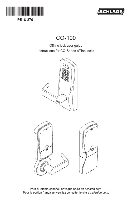
*P516-270*P516-270CO-100Offline lock user guideInstructions for CO-Series offline locksPara el idioma español, navegue hacia .Pour la portion française, veuillez consulter le site .Overview (3)Lock functions (4)Getting started (4)Construction access mode (4)Credential types and functions (5)Manual programming instructions (5)Important notes: (5)PROGRAMMING credential (5)NORMAL USE credentials (6)TOGGLE credentials (6)FREEZE credentials (6)PASS THROUGH credentials (6)OTHER programming (7)Error codes (8)Test lock operation (8)Mechanical test (8)Electronic test (8)Normal lock operation (8)Wired remote release feature (9)System requirements (9)Switch specifications, wire specifications and routing (9)Wired remote release operation (9)Wired remote release button action (9)Lock status reports (10)Reset to factory defaults (11)Batteries (12)To install or replace alkaline batteries (12)Low battery indications (12)Battery failure mode (13)LED reference (13)Schlage button (13)Optional Inside Push Button (IPB) (13)Troubleshooting (14)FCC Statements (15)This product is compliant of UL294 and ULC-S319 standard. This product’s compliance would be invalidated through the use of any add-on, expansion, memory or other module that has not yet been evaluated for compatibility for use with this UL Listed product, in accordance with the requirements of the Standards UL294 and ULC-S319. This product has been evaluated for ULC-S319 Class I.UL294 Access Control Levels tested to: Destructive Attack - Level 1; Line Security - Level 1; Endurance - Level 4; Standby Power - Level 1.2 • Schlage • CO-100 user guideThe Schlage CO-100 is a keypad-only off-line electronic lock in the CO-Series product line.• This product is listed for UL294 and ULC-S319.• Three factory-configured functions are available: 1) Classroom/Storeroom, 2) Office, and 3) Privacy.• The lock is powered by four (4) AA batteries. See Batteries on page 12 for more information.• Outside lever is normally locked.• Inside lever always allows egress.OutsideKeywayBatteryOptionalInside PushButtonCO-100-993CO-100-CYCO-100-MS3 • Schlage • CO-100 user guideThe CO-100 lock is available in one of three functions:Privacy (40): Privacy function is available on locks with firmware version 2.6.2 or higher. Lockset is normally secure. Inside Push Button is pressed to disable normal electronic access from outside (activates privacy). Another press of Inside Push Button restores normal electronic access (deactivates privacy).Office (50): Lockset is normally secure. Inside Push Button may be used to select passage or secured status.Classroom/Storeroom (70): Lockset is normally secure. Valid toggle credentials may be used to change to a passage or secure status.Follow these steps when setting up a new lock.1. Install the lock. See the installation guide that came with the lock or visit for more information.2. Test the lock for proper mechanical and electronic operation. See Test lock operation onpage 8 for more information.3. When ready to set up for normal use, enter a new programming code, then program theuser credentials. See Manual programming instructions on page 5.4. Familiarize yourself with the information in this guide.Save this user guide for future reference.Construction access mode is used to allow access before the lock has been programmed, and for testing purposes. Construction access mode is enabled by default.Offline locks with keypads have a default PIN of 13579 and “#”, which can be used for installation, testing and construction access.• To test, enter the default PIN (13579 and “#”).• The Schlage button will blink and the lock will unlock.• The default PIN is automatically deleted when a new programming credential is created.TIPIf you press the default PIN code on a new lock and the code is not accepted, the lock has already been programmed.If the new PIN is not known, or to put the lock back into construction access mode, reset the lock to factory settings. See Reset to factory defaults on page 11 for more information.4 • Schlage • CO-100 user guideProgramming credential: A 5 digit code used only for lock programming.PIN credential: A 3-6 digit code entered on the keypad.Note: A unique credential must be used for each credential type described below (for example, a single credential may not be used for both normal use and toggle functions).Manual programming instructionsImportant notes:L Wait for the Schlage button LEDs to stop flashing before continuing to the next step. L Programming mode will time out if no entry is made in 20-25 seconds. Time out isindicated by three left and nine right red blinks of the Schlage button.L An incorrect entry is indicated by a solid red left and blinking green right LED on the Schlage button. Refer to Error codes on page 8 to interpret error code patterns.L A unique PIN must be used for each credential type (for example, a single PIN may not be used for both normal use and toggle functions). PROGRAMMING credentialshould not be used.5 • Schlage • CO-100 user guideNORMAL USE credentialsNote: Until a new Normal Use PIN is created, the default PIN is6 • Schlage • CO-100 user guide7 • Schlage • CO-100 user guide8 • Schlage • CO-100 user guideL All error codes are indicated on the Schlage button by a solid red left LED, and ablinking green right LED. The number of green blinks indicates the error code.RedGreen Laboratories Inc.Test lock operationIf you encounter problems while performing any of the following tests, review the installation guide and correct any problems.Mechanical test1. Rotate the inside lever or depress the push bar to open the door. Operation should besmooth, and the latch should retract.2. Insert the key into the keyway and rotate the key and the outside lever to open the door.Operation should be smooth, and the latch should retract.Electronic test1. Press any number key. The lock will beep. Use the default PIN (13579 and “#”) to verifyaccess.Normal lock operationAfter PIN credentials have been programmed, enter a PIN to operate the lock:Press a valid PIN. The green LED will blink and access is granted.The “#” key is used as ENTER key for PINs with fewer than six digits. Default minimum digits is six (6). PIN length may be manually configured so users do not have to push the “#” key (see Change PIN length on page 7).If the PIN credential is entered incorrectly, press “*” to start over.Wired remote release operation• When the remote release button is pressed the lock will unlock for the programmed relock delay period. The green Schlage LEDs and the green inside push button LED will turn on to indicate the lock is unlocked. If the beeper function is turned on, the beeper will sound one time to indicate the lock is unlocked.• After the relock delay period has expired, the green Schlage LEDs and the green inside push button LED will turn off. If the beeper function is turned on, the beeper will sound two times to indicate the lock is relocked.Wired remote release button action• If the remote release button is pressed and held, the release will function only one time, even in the event the button is held longer than the relock delay period.• If the remote release button is quickly pressed repeatedly, the release will function only one time. Any additional button presses during the relock delay period are ignored.• Once the lock relocks, the next press of the remote release button will activate a newrelease cycle.9 • Schlage • CO-100 user guide10 • Schlage • CO-100 user guideFollow the steps below to obtain lock status reports:L Lock status reporting is available with firmware version 2.5.0 or higher.L The left and right Schlage button LEDs will blink red once with each button press,followed by the status indicator as described below.If no entry is made within 20 seconds of the solid green right LED, then timeout will occur..All information in the main controller in the lock will be deleted and reset to factory defaults! Main controller configurations that will reset to factory default include: programming and user codes.The door must be locked (not toggled open or in the middle of normal access) before resetting to factory defaults.Follow these steps to reset to factory defaults.1. Remove the top inside cover.2. Remove one battery from the battery pack to disrupt power. Wait 5 to 10 seconds forpower to run out in the lock.3. Press and hold the Schlage button while reconnecting the battery into the battery packto resupply power.4. Continue holding the Schlage button, and wait for two beeps to sound and two greenblinks of the Schlage button.5. Release the Schlage button.6. Press and release the Schlage button three (3) times within 10 seconds of the beepsand blinks at step 4. One beep will sound and one red blink will occur with each press. 7. The Schlage button will light green for one second and a one-second beep will sound,indicating that the lock has been reset.L If the Schlage button is not pressed 3 times within 10 seconds, two beeps and two red blinks indicate timeout.8. Replace the top inside cover.To test, enter 13579 and “#”. The Schlage button will blink and the lock will unlock momentarily.11 • Schlage • CO-100 user guide12 • Schlage • CO-100 user guideTo install or replace alkaline batteries L Changing batteries does not affect any programmed data.1. Remove the battery cover.2. Remove the battery bracket. Do not allow the battery pack to hang from the wires.3.Install the new batteries (install only new AA Alkaline batteries). Make sure the batteries are installed in the correct orientation.4. Reinstall the battery pack and battery bracket.5. Reinstall the battery cover, making sure the plug is to the right of the battery pack (CY ,MS, and MD locks). Be careful not to pinch the battery wires when installing the battery cover.CAUTION! Danger of explosion if batteries are incorrectly replaced! Replace only with new AA alkaline batteries. Dispose of used batteries according to the manufacturer’s instructions.This product has been evaluated for ULCS319 compliance with AA batteries listed below. For installations requiring ULCS319, these battery models should be used.Duracell PC1500, MN1500; Energizer E91, EN91, AX91, XR91; RayoVac 815, 815-HECY , MS 993!Low battery indicationsBattery failure modeIn the event of battery failure, the lock will fail As-Is (lock remains in current state, locked or unlocked, until batteries are replaced).Schlage button* The red blinks will turn amber for occupancy indicator when the lock’s battery is low.Optional Inside Push Button (IPB)1 Unlocking the lock with the IPB will cause the lock to remain unlocked until the IPB is depressed again.* The red blinks will turn amber for occupancy indicator when the lock’s battery is low.13 • Schlage • CO-100 user guide14 • Schlage • CO-100 user guideThis device complies with Part 15 of the FCC Rules. Operation is subject to the following two conditions:1. this device may not cause harmful interference, and2. this device must accept any interference received, including interference that maycause undesired operation.15 • Schlage • CO-100 user guidePrinted in U.S.A.P516-270 Rev. 03/20-L。
PMC100控制器_说明书
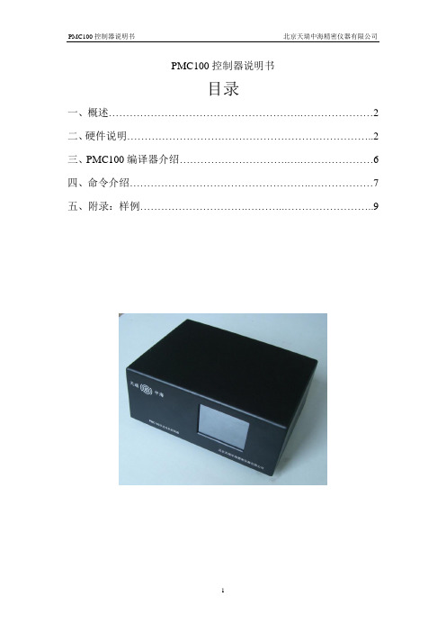
PMC100控制器说明书目录一、概述 (2)二、硬件说明 (2)三、PMC100编译器介绍 (6)四、命令介绍 (7)五、附录:样例 (9)一、概述:敬爱的用户:你好!非常感谢您使用PMC100 步进电机控制器,和国内外同类高档控制器相比,先进的特点如下:1.1、用户编程方便,使用PMC100 控制器,您不必再为修改程序发愁。
该控制器提供独立的编程环境,不必借助任何工具,您可以随时对程序进行修改或重写。
她的指令设置合理并简单,符合人们的思维习惯,不会在指令的熟悉上花费您太多的宝贵时间;。
1.2、可控制一轴步进电机。
PMC100 控制器具有驱动一轴步进电机的能力,并带两个硬件限位点, 一个参考零位。
控制步进电机电流0~2A。
1.3、显示方式为真彩TFT液晶屏;1.4、按键采用触摸屏;1.5、通用2个输入、2个输出点,实现逻辑控制;。
1.6、高达1024字节的存储空间;支持计算机程序下载;可脱离PC独立控制1.7、支持指令控制,进行傻瓜式控制;1.8、支持计算机控制;1.9、拥有简单数据输入软件,实现简单控制。
2.0、提供二次开发的接口和样例程序,方便客户二次开发。
二、硬件说明:2.1、硬件说明;1、适用于步进电机的各种场合控制应用;2、提供运算指令,可进行复杂控制;3、2个通用输入点、2个输出点,实现逻辑控制;4、2个硬件限位点;1个参考零位。
5、最高128细分步进控制,出厂默认为8细分;2.2、性能指标;1、输出脉冲频率:单轴控制400-40000Hz 任意值可设定;2、1K 用户程序空间;3、当前坐标实时显示;2.3机箱正视图:1、采用2.8寸TFT液晶屏,触摸屏;2、实时显示当前位置;初速度;加速度;终速度。
3、提供四个快捷键:前进;后退;运行;回零。
前进:每按按一次,前进10000个脉冲。
后退:每按一次,后退10000个脉冲。
回零:回到零点。
运行:运行已经存储在flash中的程序(停止键,即停止当前运动)。
SCR100用户手册(1.1版)20091223
SCR100用户手册版本:1.1版日期:2009年12月内容介绍本文档主要介绍SCR100产品的安装注意事项及连线方法,并简要介绍了考勤软件的相关操作。
重要申明首先感谢您选择我公司的产品。
在使用前,请您仔细阅读本产品的说明书。
以避免设备受到不必要的损害!本公司提醒您正确使用,将得到良好的使用效果和验证速度。
非经我公司书面同意,任何单位和个人不得擅自摘抄、复制本手册内容的部分或全部,并不得以任何形式传播。
本手册中描述的产品中,可能包含我公司及其可能存在的许可人享有版权的软件,除非获得相关权利人的许可,否则,任何人不能以任何形式对前述软件进行复制、分发、修改、摘录、反编译、反汇编、解密、反向工程、出租、转让、分许可以及其他侵权软件版权的行为,但是适用法禁止此类限制的除外。
由于产品的不断更新,我公司不能承诺实际产品与该资料一致,同时也不承担由于实际技术参数与本资料不符所导致的任何争议,任何改动恕不提前通知。
目录1.使用须知 (1)1.1 产品功能简介 (1)1.2正面图 (1)1.3安装注意事项 (2)1.4系统安装示意图 (4)1.5通讯连接示意图 (5)2.安装 (6)2.1固定后盖板 (6)2.2连接外围设备 (7)2.2.1门磁连接线 (8)2.2.2出门按钮连接线 (8)2.2.3报警器连接线 (9)2.2.4门锁连接线 (9)2.2.5 以太网连接线 (13)2.2.6 RS232连接线 (14)2.2.7 RS485接口线 (15)2.2.8 Wiegand输出连接线 (16)2.2.9 电源连接线 (17)2.3 固定设备 (18)2.4安装后的检查 (18)3. 考勤软件简介 (19)3.1 登记设备 (19)3.2登记用户和ID卡 (20)3.3 上传和下载 (22)3.3.1 上传到设备 (23)3.3.2 下载到电脑 (24)3.4实时监控 (24)4. 其它 (26)4.1复位键 (26)4.2防拆开关 (27)1. 使用须知1.1 产品功能简介SCR100是中控科技推出的全球第一款基于TCP/IP 的门禁控制器和读头,射频卡无屏无按键专业门禁机,增加射频卡类门禁产品系列,为系统门禁方案提供更多的产品选择,该产品即可作为一体机单独控锁,也可以作为门禁控制器连接射频卡门禁读头使用,实现主从机或者反潜功能,标准的TCP/IP 协议可实现跨网段、跨网关连接组网,可内置Webserver 通过网络访问查询记录等。