NASA STD7009 建模与仿真标准★
法尔肯9火箭通过NASA的发射资格认证
法尔肯 9火箭通过 N A S A 的发射资格认证
据航天飞行在线网站报道,2 0 1 5年 5月 1 5日,空间探 索 火箭 。由于更换火箭导致部分工作要 从头 开始,包括对承包商 管理 、工艺及工程方面的审计等。 N AS A的火箭发射 鉴定分为 1  ̄ 3类 ,1 类评级最低 ,3 类 评
平 衡式 插拔 连 接器 可 以应 用于 火 箭起 飞一 定 高度 后供 气 带载 脱落 的一类 工况 ,具 有较 高 的技术 推广 意 义 。
参 考 文 献
注: ( = ) 值查 G B / T 4 0 8 6 . 1 — 1 9 8 3《 统 计分布 数值 表 正 态分布 》 中的标
准正 态分布 函 数表 。
连接 器 脱落可 靠性 要求 为 0 . 9 9 9 9 7 8以上时 ,求得
设计解 锁 力应 大于 ( 1 3 8 0 J - : 5 0 )N ( 理论值 ) 。连 接器
【 1 ] 杨瑞 刚 . 机械 可靠 性 设计 与应 用p 哪. 北京: 冶 金工业 出版社 , 2 0 0 8 . [ 2 2 】 周 正伐 , 等. 航 天可 靠性 工程 【 M】 . 北 京:中 国宇航 出版 社, 2 0 0 6 .
3 结
表 1 可靠性计算公式
应 力
正态
论
平 衡式 气 路插 拔连 接 器 的研 制 ,解 决 了适应 供 气
强度 正 态
可 靠度 公式
R= ( z )z =
,
丝 .
N ( /  ̄ L , )
| v ( , )
√ +
带载、起飞脱落 以及随动工况的插拔连接器关键设计 技 术 ,并且 设置 脱落 冗 余措 施提 高 了产 品可靠 性 ,产 品样 机 的脱 落解 锁 力试 验评 估满 足 可靠 性 指标 要 求 。
航天飞行动力学作业报告-轨道仿真及转移质量计算

航天飞行动力学作业报告——轨道仿真及转移质量计算一、问题描述1、在已知条件下考虑J2项摄动和大气阻力摄动,计算仿真航天器轨道在一年之内的变化特性,并绘制其图像。
2、在轨运行一年后,采用Hohmann 机动使轨道回到标称轨道,计算所要消耗的推进剂的质量。
二、模型建立在仅考虑J2项摄动和大气阻力摄动的假设下,可得到下列公式进行求解。
sin (1)cos ]cos (1)sin sin()cot ]sin (1)sin (1cos )]u r u u h h r u h r u r u dp dt de r er a f a f a dt p p d dt di dt d r er a f a f a f i dt p pdf f r dt e p da a e f a e f dt ωω==+++Ω===−++−+−+=++2r u dM r r f e a dt p p +−+其中r u h a a a 为摄动加速度在径向、横向、副法向方向上的加速度分量,可以用下列公式得到。
Da g a ∆=∆+22222222222222223[13sin sin ()]23sin sin[2()]23sin sin()2e r e u e h R g J i f r rR g J i f r rR g J i f r r µωµωµω∆=−−+∆=−+∆=−+22sin cos Dr Du a v a v σργσργ=−=−通过matlab 对上式进行数值迭代求解就可以得到轨道六要素在一年之内的变化特性。
三、求解六要素通过上式的迭代求解可以得到六要素在一年中变化如下:图 3-1 近地点幅角ω图3-2 真近点角f图3-3 离心率e图3-4 半长轴a图3-5 轨道倾角i图3-6 升交点赤经Ω四、六要素的理论分析对于0.25E7 s时候e产生的突变,是因为在迭代数值求解过程中,使用了两组公式分别对应于e很小(近似为圆轨道)以及e不可忽略(按椭圆轨道)的时候,当到0.5E7 s附近时,e不可忽略,de按椭圆轨道计算,会产生一个突增。
TRACE 700用户手册:高级使用和一般建模建议说明书
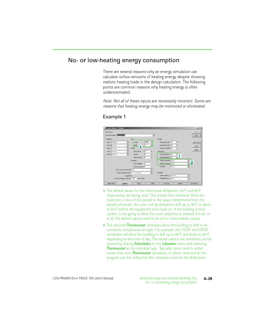
6–39CDS-PRM001-EN • TRACE 700 User’s Manual Advanced Usage and General Modeling Tips No- or low-heating energy consumption No- or low-heating energy consumptionThere are several reasons why an energy simulation cancalculate no/low amounts of heating energy despite showing realistic heating loads in the design calculation. The following points are common reasons why heating energy is often underestimated.Note: Not all of these inputs are necessarily incorrect. Some are reasons that heating energy may be minimized or eliminated.Example 11The default values for the thermostat driftpoints, 90°F and 55°F respectively, are being used. This means that whenever there are 5percent or less of the people in the space (determined from the people schedule), the room will be allowed to drift up to 90°F or down to 55°F before the equipment turns back on. If the building control system is not going to allow the room setpoints to setback this far, or at all, the default values need to be set to more realistic values.2The selected Thermostat schedules allow the building to drift to an unrealistic temperature at night. For example, the CSTAT and HSTAT schedules will allow the building to drift up to 95°F and down to 55°F , depending on the time of day. The values used in the schedules can be viewed by clicking Schedules on the Libraries menu and selecting Thermostat as the schedule type. Typically, users need to either create their own Thermostat schedules, or select none and let theprogram use the driftpoints (the schedules override the driftpoints).Not correcting this input will result in an underestimation of the coolingand heating energy at night. Refer to “Frequently asked questions” onpage6–20 for information regarding how driftpoints and thermostatschedules interact.3Large areas are being modeled as a single space. This can cause theinternal loads to negate the envelope losses, leading to anunderestimation or elimination of the heating loads in the energysimulation. Because internal loads are typically neglected during theheating design calculations, reasonable heating-design results may bereturned using this assumption. Modeling interior and perimeter areasas separate rooms will eliminate this modeling error. Refer to“Modeling large rooms and zones” on page6–45 for a detailedexplanation.Example 21The Cooling Only (Design) schedule is selected for any of the internalloads. This schedule should typically only be used for designcalculations, not for energy analysis. It simulates 100percent of theinternal loads in the building 24hours a day (except during the heating-design portion of the calculation), which may not be what is actuallyoccurring in the building. This tends to lead to the internal loadsmeeting the heating loads. To view the schedule, click Schedules onthe Libraries menu and select Utilization as the schedule type. Herethe user should be able to view the schedule and find schedules thatmore-closely follow the actual operation of the building.2The internal loads are scheduled as Available 100%. This scheduleshould not be used for internal loads. It simulates 100percent of theinternal loads in the building 24hours a day, which may not be what isactually occurring in the building. In addition, it also tells the program totake credit for the internal loads during the heating-design calculation.6–40Advanced Usage and General Modeling Tips TRACE 700 User’s Manual • CDS-PRM001-EN No- or low-heating energy consumption6–41CDS-PRM001-EN • TRACE 700 User’s Manual Advanced Usage and General Modeling TipsNo- or low-heating energy consumption This schedule tends to lead to an underestimation of heating energy and undersizing of the heating coils, due to the internal loads meeting all or most of the heating loads. To view the schedule, click Schedules on the Libraries menu. Here the user should be able to view the schedule and find schedules that more closely follow the actual operation of the building.3The custom schedule(s) for internal loads have values greater than zero for the heating-design day type. This tells the program to take credit for the internal loads during the heating-design calculation. This tends to lead to undersizing of the heating coils and is not common design practice. To view the schedule, click Schedules on theLibraries menu. Here the user should be able to view the schedule and the individual day types.Example 31No infiltration has been input on the Airflows tab of Create Rooms .Infiltration is air from outside the building that leaks into the room, often adding to the heating requirement.2No VAV minimum airflow has been input for VAV systems. This can result in no (or minimal) airflow being supplied to the space in heatingmode.6–42Advanced Usage and General Modeling TipsTRACE 700 User’s Manual • CDS-PRM001-ENNo- or low-heating energy consumption Example 41The heating supply-air temperature has been input at an unrealistically low temperature. The capacity of the heating coil is calculated based on the airflow through the coil and the temperature difference across the coil. If coil capacity is underestimated, the energy consumed by the coil will also be underestimated.Example 51The selected fan schedule does not allow the fan to run at hours when heating loads occur. If the fan is turned off, the heating coils cannot consume energy. Schedules for fans should be used only when the fans are turned off for certain time periods and not allowed to turn back on no matter what the temperature is in the space. The schedules Off (0percent) and Heating Only (Design) would be two6–43CDS-PRM001-EN • TRACE 700 User’s Manual Advanced Usage and General Modeling TipsNo- or low-heating energy consumption examples of incorrect schedule selection. Refer to “Frequently asked questions” on page 6–20 for additional details regarding how fan schedules and fan cycling operate in TRACE 700.Example 61The heating coil(s) capacity has been zeroed out. This will cause the program to eliminate all energy associated with the coil(s).2The heating coil(s) have been scheduled off during hours when heating loads occur. If the coil(s) are turned off, they cannot consume energy. Schedules for coils should be used only when the coils are turned off for certain time periods and not allowed to turn back on no matter what the temperature is in the space.Example 71The heating equipment schedule does not allow the heatingequipment to run during hours when heating loads occur. If the heatingequipment is turned off, then it cannot consume energy or meet thecalculated heating loads.Note: Switching to a full-year (8760 analysis) will typically provide a more-accurate estimation of heating energy consumption. Refer to “Addingweather locations and activating the 8760 calculation methodology” onpage6–137.6–44Advanced Usage and General Modeling Tips TRACE 700 User’s Manual • CDS-PRM001-EN No- or low-heating energy consumption。
培训教材17-项目计划综合控制方法

(PMB)
2000 1000
BCWS BCWP
ACWP
Cost Variance
Projected Program
Delay
Schedule Variance
0
Jan Feb Mar Apr May Jun Jul Aug Sep Oct Nov Dec Jan Feb Mar Apr May Jun
合同
已批准但未量化的工作
管理费备用金 未分配的预算
已经分配的预算 [S of all CAs]
中国核工业第二三建设公司三门项目部 5
赢得值的几个参数
计划值PV
应该完成多少工作?
赢得值EV
完成了多少预算工作?
实际成本AC
完成工作的成本是多少?
完工预算BAC 全部工作的预算是多少?
完工估算EAC 全部工作的成本是多少?
1984 FAA & NASA Lewis Research Center—PMS
1985 NASA Johnson Space Flight Center— PMS
1987 DOD—Revised DOD C/SCSC JIG
1988 NASA Marshall SFC—Revised PMS (MMI 8020.7C, 44 Criteria)
进度绩效指数SPI SPI=已完成工作预算成本BCWP/ 计划工作预算成本BCWS =赢得值EV / 计划值PV
SPI>1 活动比计划提前完成,很好。 SPI=1 活动按计划进度完成,好。 SPI<1 活动较计划进度滞后完成,差。
中国核工业第二三建设公司三门项目部 13
赢得值分析
6000 5000 4000 3000
军工产品建模与仿真技术状态管理研究
军工产品建模与仿真技术状态管理研究米凯1皮赞2高林3(1.中国航天标准化研究所,北京100071; 2.北京宇航系统工程研究所,北京100076;3.北京机电工程总体设计部,北京100854冤摘要建模与仿真技术在军工产品研制过程的应用越来越广泛,有效的技术状态管理是建模 与仿真质量保证的重要方面。
识别了建模与仿真过程的技术状态项,对建模与仿真技术状态基线的建 立、技术状态的标识、更改、记实、审核等活动相关要求和做法进行了详细论述,对军工产品开展建 模与仿真技术状态管理提供借鉴和参考。
关键词军工产品建模与仿真技术状态管理引言建模与仿真技术是以相似原理、系统技术、信息技术及仿真应用领域的有关专业技术为基础,以计算机系统、与应用有关的物理效应设备及仿 真器为工具,利用模型对系统渊已有的或设想的冤 进行研究的一门多学科的综合性技术。
建模和仿 真技术与高性能计算一起,正成为认识、改造客 观世界的重要手段。
建模与仿真技术在军工产品研制过程的应用领 域越来越广泛,作为产品研制过程的重要组成,建 模与仿真技术状态管理要求遵循产品研制技术状态 管理的相关标准,如GJB3206A—2010《技术状 态管理》等。
现对军工产品研制过程中建模与仿 真的技术状态管理进行论述,包括建模与仿真技术 状态标识、技术状态控制、技术状态记实、技术状 态审核等相关要求和做法。
1建模与仿真技术状态管理的特点技术状态管理的概念最早来源于美国的军用航 空航天制造业,是复杂产品系统工程管理的重要组 成部分。
我国于1998年正式发布了 GJB 3206-98《技术状态管理》,并于2010年进行了修订。
技术状态管理要求能够随时反映技术状态项目的执行情 况,能对每个技术状态项目和技术状态项目组成的 系统及其基线提供追溯性和技术状态控制的全部相 关信息[2]。
在当前军工产品研制过程中,数字化建模、仿 真与优化等信息技术及先进数字化制造技术大量应 用。
《控制系统建模与仿真》课后习题-2021版
《控制系统建模与仿真》课程习题(1)一、“投针实验”的历史价值在人类数学文化史中,对圆周率 精确值的追求吸引了许多学者的研究兴趣。
在众多的圆周率计算方法中,最为奇妙的是法国物理学家布丰(Boffon)在1777年提出的“投针实验”。
试回答下列问题:1、试对“投针实验”的机理给出一种直观形象的物理解释?2、有人说“布丰/ Boffon(投针实验)是仿真技术的奠基者”,为什么?3、试用MATLAB语言编制“投针实验”的仿真程序,仿真证明之。
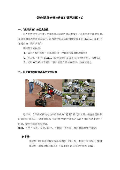
二、自平衡式两轮电动车的安全问题近年来,自平衡式两轮电动车产品成为“抢眼”的代步工具,但也出现很多问题(如上图所示);试根据你所了解的情况就“平衡车产品是否可以合法上路?”问题,给出你的意见与建议。
提示:可从“技术、安全、法律、可持续”等方面,有理有据地展开讨论。
参考书:张晓华《控制系统数字仿真与CAD》 (第4版) 机械工业出版社 2020张晓华《系统建模与仿真》(第2版)清华大学出版社 2016《控制系统建模与仿真》课程习题(2)一、一阶直线倒立摆系统的建模问题对于教材中图2-7所示的一阶直线倒立摆系统,基于牛顿定律所建立的数学模型(如教材的图2-8所示),试问:这个数学模型是否正确,给出你的分析与证明。
提示:(1)基于MATLAB仿真进行模型验证(参见教材第四章第三节);(2)应用“拉格朗日方程”方法建模,进行结果对比。
二、一阶直线双倒立摆系统的可实现问题如下图所示的一阶直线双倒立摆系统,试问:能否通过控制力F实现“在保持两杆不倒的条件下,使小车在直线X方向的位置任意移动”?提示:(1)建立系统数学模型;(2)应用现代控制理论的“能控性定理”进行分析。
参考书:张晓华《控制系统数字仿真与CAD》 (第4版) 机械工业出版社 2020张晓华《系统建模与仿真》(第2版)清华大学出版社 2016《控制系统建模与仿真》课程习题(3)一、水箱液位控制系统设计问题如下图所示的“水箱液位系统”,试回答下列问题:1、试给出含有(控制器+传感器)的“水箱液位控制系统”方案;2、试依据“流体力学”的基本概念,建立系统的数学模型;3、若使系统液位控制实现稳态无静差,试给出PID控制器设计方案;二、水箱液位控制的拓展问题试回答下述问题:1、某人在上述“水箱液位控制系统”中,采用单片机作控制器,程序设计为“增量式PI控制算法”,如果控制系统在“阶跃给定”下存在稳态误差,试问这种情况是否合理?为什么?2、对于上图所示的“水箱液位系统”,在下排水出口处流体呈“紊流”状态,试证明:其流量与液位高度的关系为Q=K∙√H。
ΣΔ ADC的原理、系统设计和建模仿真

录
3. 模数转换器概述 ................................................................................................................................. 2 3.1 ADC 的一些主要性能指标 ........................................................................................................ 3 3.2 ADC 提高信噪比的方法 ............................................................................................................ 5 3.2.1 过采样 ............................................................................................................................................. 5 3.2.2 噪声整形 ........................................................................................................................................ 6 3.2.3 多位量化器 .................................................................................................................................... 8 3.3 调制器结构 ............................................................................................................................................ 8 3.3.1 单环结构 ........................................................................................................................................ 9 3.3.2 级联结构 ...................................................................................................................................... 14 3.3.3 采用多位量化器的调制器 ...................................................................................................... 16 3.4 降采样滤波器..................................................................................................................................... 16 3.5 宽带 ADC 研究现状 ..................................................................................................................... 16 3.6 小结 ....................................................................................................................................................... 17 4. 级联调制器的系统设计 ......................................................................................................................... 18 4.1 调制器体系结构的确定 ................................................................................................................... 18 4.2 宽带级联调制器问题与改善方法 ................................................................................................ 24 4.2.1 失真................................................................................................................................................ 24 4.2.2 模拟与数字的系数失配 ........................................................................................................... 31 4.2.3 多比特 DAC 引入的非线性 .................................................................................................... 34 4.3 低失真混合级联结构与参数设计 ................................................................................................ 40 4.3.1 低失真混合级联结构的提出 ................................................................................................... 40 4.3.2 低失真混合级联结构的参数设计 ......................................................................................... 43 4.4 非理想因素与误差来源 ................................................................................................................... 43 4.4.1 热噪声 ......................................................................................................................................... 44 4.4.2 元器件的失配 ............................................................................................................................. 47 4.4.3 积分器的非理想特性.............................................................................................................. 48 4.4.4 其它误差来源 ........................................................................................................................... 52 4.5 小结 ....................................................................................................................................................... 56
空间站舱段精细化声振耦合建模与仿真
第22卷第6期2016年12月载人航天Manned SpaceflightVol. 22 No. 6Dec. 2016地月空间站舱段精细化声振耦合建模与仿真仲作阳U2,张海联\周建平2(1.载人航天总体研究论证中心,北京100094 ; 2.中国载人航天工程办公室,北京100034)摘要:在地月空间站长期飞行中,持续、过度的嗓声环境会危害航天员的身心健康,并影响工作 效率。
地月空间站设备功率大、噪声源数目多、噪声指标严苛,给噪声控制和设计带来很大的 挑战。
为确保舱段噪声指标满足要求,基于声学有限元方法,根据已掌握的噪声源频谱特性、舱段构型布局、设备安装方式等建立整舱复杂声振耦合精细化噪声仿真模型。
对环控、热控及 推进分系统等多种嗓声源单独工作或同时工作时密封舱内的嗓声进行仿真,得到舱内低频嗓 声水平特性分布。
结果表明:声振耦合下舱内的总体噪声水平远高于不考虑声振耦合的情况,并导致三个航天员睡眠区头部的声压级分布差异较大。
此外,睡眠区粘贴吸声材料后,对高频 段的吸声降噪效果明显,对中频段有一定的降噪效果,但对低频段几乎不起作用。
关键词:地月空间站;声振耦合;噪声仿真与评价;声学有限元中图分类号:T B53 文献标识码:A文章编号=1674-5825(2016)06-0700-06 Modeling and Simulation of Vibration-acoustics Coupling inEarth-^oon Space StationZHONG Zuoyang1,2,ZHANG Hailian1 ,ZHOU Tianping2(1. Manned Space System Research Center,Beijing 100094, China; 2. China Manned Space Agency,Beijing 100034, China) Abstract:D u rin g the long d u ra tio n m anned space m issions of the F arth-M oo n space s ta tio n,the excessive noise en viro nm en t w ill harm the health of astron au ts,and affect the w o rk e ffic ie n c y.Due to the fa ct that the equipm en t pow er of F a rth-M o o n space station is b ig,the q u a n tity of noise source is m a n y,and the noise in de x is h a rs h,the noise co n tro l and design face m any challenges.To m eet the noise in d e x,the acoustic fin ite elem ent m ethod was adopted to establish the co m p lica ted v ib ra tio n-acoustics c o u p lin g sim u la tio n m o d e l.By m u lti-c o n d itio n s im u la tio n,the cha racteristic d is trib u tio n of the low frequ en cy noise le v e l was o b ta in e d.The resu lt showed that the noise le ve l un d e r the co n d itio n of v ib ra tio n-a co u stics co u p lin g was ob viously h ig h e r than that of the n o n-co u p lin g c o n d itio n. M e a n w h ile,the vib ra tio n-a co u stics co u p lin g le d to the sig n ifica n t differences of the noise d is trib u tio n am ong the three astronaut sleeping areas.In a d d itio n,the effect of sound absorption and noise red u c tio n was q u ite obvious in the h igh frequency band by pasting w ith the sound absorbing m aterialon the sleeping a re a,b u t there was little effect on the lo w frequ en cy b a n d.Keywords:F a rth-M o o n space s ta tio n;v ib ra tio n-a co u stics c o u p lin g;noise sim u la tio n and evaluat io n;acoustics fin ite elem ent1引言地月空间站环控通风系统、压气机/液冷模块 以及控制力矩陀螺(C M G)等环境控制设备,热控制设备,姿态控制设备均会产生噪声,长时间持 续、过度的噪声环境会危害航天员的身心健康,导 致航天员的工作效率下降、睡眠质量差、易产生疲 劳,还会造成航天员之间的交流障碍,从而影响日收稿日期:2016-05-31;修回日期:2016-10-30基金项目:国家自然科学基金(11402303);中国博士后基金(2016M592931)作者简介:仲作阳(1984 -),男,博士 ,工程师,研究方向为空间站噪声评价与控制。
NASA-STD-8739.3

NASA-STD-8739.3 w/Change 2December 1997PREVIOUS VERSION PUBLISHED AS NHB 5300.4(3A-2)SOLDERED ELECTRICALCONNECTIONS NASA TECHNICAL STANDARDNational Aeronautics andSpace AdministrationREVISIONSREVISION DESCRIPTION DATE Initial Issue12/15/97(FDG) Change 1Typographical corrections to the headers12/8/00on pages A10 and A12 (Changed (WBHIII)Acceptable to Unacceptable)Change 2Replaced erroneous figure 14 on page A-6 1/18/01(which was a duplicate of figure 8) with the (WBHIII)correct figureFOREWORDEffective Date: December 15 1997This Standard provides a baseline for NASA project offices to use when preparing or evaluating process procedures for the manufacture of space flight hardware or mission critical ground support equipment.This Standard:a. Prescribes NASA’s process and end-item requirements for reliable soldered electricalconnections.b. Establishes responsibilities for training personnel.c. Establishes responsibilities for documenting process procedures including supplierinnovations, special processes, and changes in technology.d. For the purpose of this Standard, the term supplier is defined as in-house NASA,NASA contractors, and subtier contractors.NASA Installations shall:a. Review and invoke the provisions of this Standard for procurements involving handsoldering of space flight hardware and mission critical ground support equipment.b. Review and invoke the provisions of this Standard for in-house operations involvinghand soldering of space flight hardware and mission critical ground supportequipment.c. Tailor specific provisions of this Standard to address program or unique contractual ormission requirements.d. Assure that NASA suppliers invoke this Standard on subcontractors, purchase orders,and on subtier suppliers where applicable.e. Furnish copies of this Standard in the quantities required to NASA suppliers andsubtier suppliers.Questions concerning the application of this Standard to specific procurements shall be referred to the procuring NASA installation, or its designated representative.This Standard cancels NHB 5300.4(3A-2), “Requirements for Soldered Electrical Connections.”This Standard shall not be rewritten or reissued in any other form not approved by NASA.Other processes not covered by this Standard may be required. The design, materials, and processes shall be defined in engineering documentation.Comments and suggestions for improving this Standard may be submitted using the form “NASA Technical Standard Improvement Proposal.” A copy of the form is included in Appendix B.Frederick D. GregoryAssociate Administrator forSafety and Mission AssuranceDISTRIBUTION:SDL1 (SIQ)NASA TECHNICAL STANDARDS FOR SPACE FLIGHT AND MISSION CRITICAL GROUND SUPPORT HARDWARENASA Technical Standards can be found on the World Wide Web at URL addresshttp://www//office/codeq/qdoc.pdf.Title Number Soldered Electrical Connections NASA-STD-8739.3 Crimping, Interconnecting Cables, Harnesses, and Wiring NASA-STD-8739.4Fiber Optic Terminations, Cable Assemblies, and Installation NASA-STD-8739.5 Workmanship Standard for Staking and Conformal Coating ofNAS 5300.4(3J-1)Printed Wiring Boards and Electronic AssembliesWorkmanship Standard for Surface Mount Technology NAS 5300.4(3M)Standard for Electrostatic Discharge Control (ExcludingNASA-STD-8739.7 Electrically Initiated Explosive Devices)CONTENTSPARAGRAPH PAGEFOREWORD (i)TABLE OF CONTENTS (iv)LIST OF FIGURES (vii)LIST OF TABLES (viii)LIST OF APPENDICES (viii)1.SCOPE....................................................................................................................1-1 1.1Purpose..........................................................................................................1-11.2Applicability...................................................................................................1-12.APPLICABLE DOCUMENTS................................................................................2-1 2.1Applicable Specifications................................................................................2-1 2.2Other Documents...........................................................................................2-2 3DEFINITIONS AND ACRONYMS.........................................................................3-13.1Definitions......................................................................................................3-1 3.2Acronyms.......................................................................................................3-74.GENERAL...............................................................................................................4-1 4.1General..........................................................................................................4-1 4.2Reliable Soldered Connections.......................................................................4-1 4.3Documentation...............................................................................................4-2 4.4Approval of Departures From This Standard..................................................4-24.5Rework and Repair........................................................................................4-25.TRAINING AND CERTIFICATION PROGRAM...................................................5-1 5.1General..........................................................................................................5-1 5.2Vision Requirements......................................................................................5-1 5.3Certification Levels........................................................................................5-1 5.4Training Program Requirements.....................................................................5-2 5.5Documentation...............................................................................................5-2 5.6Maintenance of Certification Status................................................................5-3 5.7Training Resources.........................................................................................5-46.FACILITIES, EQUIPMENT, MATERIALS, AND PARTS.....................................6-1 6.1Facility Cleanliness.........................................................................................6-1 6.2Environmental Conditions..............................................................................6-1 6.3Electrostatic Discharge Requirements.............................................................6-2 6.4Tool and Equipment Control..........................................................................6-2 6.5Soldering Tools and Equipment......................................................................6-3 6.6Conductor Preparation Tools.........................................................................6-4 6.7Thermal Shunts..............................................................................................6-5 6.8Inspection Optics...........................................................................................6-5 6.9In-Process Storage and Handling....................................................................6-5 6.10Material Solderability.....................................................................................6-5 6.11Solder............................................................................................................6-5 6.12Liquid Flux.....................................................................................................6-6 6.13Solvents and Cleaners.....................................................................................6-66.14Personnel Protection......................................................................................6-77.PREPARATION FOR SOLDERING.......................................................................7-1 7.1Preparation of Soldering Tools.......................................................................7-1 7.2Preparation of Conductors..............................................................................7-17.3Preparation of Printed Wiring Boards, Terminals, and Solder Cups.................7-28.PARTS MOUNTING...............................................................................................8-1 8.1General..........................................................................................................8-1 8.2Mounting of Terminals...................................................................................8-3 8.3Mounting of Parts to Terminals......................................................................8-4 8.4Mounting of Parts to PWB’S..........................................................................8-58.5Lead Terminations, Printed Wiring Boards.....................................................8-89.ATTACHMENT OF CONDUCTORS TO TERMINALS........................................9-1 9.1General..........................................................................................................9-1 9.2Turret and Straight Pin Terminals...................................................................9-2 9.3Bifurcated Terminals......................................................................................9-4 9.4Hook Terminals.............................................................................................9-7 9.5Pierced Terminals...........................................................................................9-8 9.6Solder Cups (Connector Type).......................................................................9-8 9.7Solder Cups (Swaged Type)...........................................................................9-9 9.8Insulation Sleeving Application......................................................................9-910.SOLDERING TO TERMINALS............................................................................10-1 10.1General........................................................................................................10-1 10.2Solder Application........................................................................................10-1 10.3High Voltage Terminations...........................................................................10-110.4Solder Cleaning............................................................................................10-211.HAND SOLDERING OF PRINTED WIRING ASSEMBLIES..............................11-1 11.1General........................................................................................................11-1 11.2Solder Application........................................................................................11-111.3Solder Cleaning............................................................................................11-312.AUTOMATIC WAVE SOLDERING....................................................................12-1 12.1General........................................................................................................12-1 12.2Preparation and Assembly............................................................................12-2 12.3Process Parameters......................................................................................12-2 12.4Wave Soldering............................................................................................12-2 12.5Cleaning.......................................................................................................12-312.6Inspection....................................................................................................12-313.QUALITY ASSURANCE PROVISIONS..............................................................13-1 13.1General........................................................................................................13-1 13.2Magnification Aids.......................................................................................13-1 13.3Documentation Verification..........................................................................13-1 13.4Documentation Authorization.......................................................................13-2 13.5Verification of Tools, Equipment, and Materials...........................................13-313.6Inspection Criteria........................................................................................13-314.CLEANLINESS REQUIREMENTS......................................................................14-1 14.1General........................................................................................................14-1 14.2Cleanliness Testing.......................................................................................14-1 14.3Testing Frequency........................................................................................14-1 14.4Test Limits...................................................................................................14-1 14.5Resistivity Of Solvent Extract Test...............................................................14-114.6Sodium Chloride (NacI) Equivalent Ionic Contamination Test......................14-215.VERIFICATION....................................................................................................15-1 15.1General........................................................................................................15-1LIST OF FIGURESFigure 6-1. Comfort Zone -- Temperature Versus Humidity Requirements...............................6-1 Figure 8-1. Terminal Damage...................................................................................................8-3 Figure 8-2. Roll Flange Terminal..............................................................................................8-3 Figure 8-3. V-Funnel Type Swage............................................................................................8-4 Figure 8-4. Elliptical Funnel Type Swage.................................................................................8-4 Figure 8-5. Stress Relief Examples...........................................................................................8-5 Figure 8-6. Horizontal Mount...................................................................................................8-5 Figure 8-7. Vertical Mount.......................................................................................................8-6 Figure 8-8. Radial Leaded Parts................................................................................................8-6 Figure 8-9. Hole Obstruction....................................................................................................8-7 Figure 8-10. Stress Relief Part Termination..............................................................................8-7 Figure 8-11. Bend Angle..........................................................................................................8-7 Figure 8-12. Conductors Terminating on Both Sides................................................................8-8 Figure 8-13. Lapped Lead Height above Board........................................................................8-9 Figure 8-14. Lapped Round Termination................................................................................8-10 Figure 8-15. Lapped Ribbon Leads.........................................................................................8-11 Figure 8-16. Clinched Termination.........................................................................................8-12 Figure 8-17. Lead Bend..........................................................................................................8-12 Figure 8-18. Straight-Through Termination............................................................................8-13 Figure 8-19. Straight-Through Lead Retention.......................................................................8-13 Figure 9-1. Wrap Orientation...................................................................................................9-2 Figure 9-2. Conductor Wrap....................................................................................................9-3 Figure 9-3. Turret Terminal......................................................................................................9-4 Figure 9-4. Continuous Run Wrapping--Turret Terminals.........................................................9-4 Figure 9-5. Bottom Route Connections to Bifurcated Terminals...............................................9-5 Figure 9-6. Side Route Connections to Bifurcated Terminals....................................................9-6LIST OF FIGURES - CONT.Figure 9-7. Lead Wrap.............................................................................................................9-7 Figure 9-8. Continuous Run Wrapping--Bifurcated Terminals...................................................9-7 Figure 9-9. Continuous Run Wrapping--Bifurcated Terminals Alternate Procedure...................9-7 Figure 9-10. Connections to Hook Terminals...........................................................................9-8 Figure 9-11. Connections to Pierced Terminals.........................................................................9-8 Figure 9-12. Connections to Solder Cups (Connector Type).....................................................9-9 Figure 9-13. Connections to Swaged Type Solder Cup.............................................................9-9 Figure 10-1 Solder-Ball Termination.....................................................................................10-2 Figure 11-1. Heel Fillet...........................................................................................................11-2 Figure 11-2. Round Lead Termination....................................................................................11-3LIST OF TABLESTable 6-1. Solvents and Cleaners..............................................................................................6-6 Table 7-1. Solder Contaminant Levels Maximum Allowable Percentby Weight of Contaminant.....................................................................................7-2 Table 14-1. Cleanliness Test Values.......................................................................................14-2LIST OF APPENDICESAPPENDIX A:ACCEPTABLE AND UNACCEPTABLE SOLDER CONNECTIONS........A-1 APPENDIX B:NASA TECHNICAL STANDARD IMPROVEMENT PROPOSAL.............B-1CHAPTER 1 - SCOPE1.1Purpose1.This publication sets forth requirements for hand and wave soldering to obtain reliable electrical connections. The prime consideration is the physical integrity of solder connections.2.Special requirements may exist that are not covered by or are not in conformance with the requirements of this publication. Engineering documentation shall contain the detail for such requirements, including modifications to existing hardware, and shall take precedence over appropriate portions of this publication when approved in writing by the procuring NASA Center prior to use.1.2Applicability1.This publication applies to NASA programs involving soldering connections for flight hardware, mission critical ground support equipment, and elements thereof, and wherever invoked contractually.2.This publication does not define the soldering requirements for Surface Mount Technology (SMT).THIS PAGE INTENTIONALLY LEFT BLANKCHAPTER 2 - APPLICABLE DOCUMENTS2.1Applicable SpecificationsCopies of the following specifications, when required in connection with a specific procurement, can be obtained from the procuring NASA Center or as directed by the contracting officer. Unless otherwise specified, the issue in effect on the date of invitation for bids or requests for proposal shall apply. The following related documents form a part of this publication to the extent specified herein.FEDERAL SPECIFICATIONS:TT-I-735Isopropyl AlcoholO-E-760Ethyl Alcohol (Ethanol) Denatured Alcohol; ProprietarySolvents and Special Industrial SolventsO-M-232"Methanol (Methyl Alcohol)"NASA SPECIFICATIONS:NHB 5300.4 (3L)Standard for Electrostatic Discharge Control (ExcludingElectronically Initiated Explosive Devices)NHB 1700.1(V1)NASA Safety Policy and Requirements DocumentNHB 8060.1C Flammability, Odor, Offgassing and CompatibilityRequirements and Test Procedures for Materials inEnvironments that Support CombustionNATIONAL STANDARDS:American National Standards Institute (ANSI):ANSI/J-STD-004Requirements for Soldering FluxesANSI/J-STD-006Requirements for Electronic Grade Solder Alloys andFluxed and Non-Fluxed Solid Solders for ElectronicSoldering ApplicationsANSI/NCSL Z540-1-1994General Requirements for Calibration Laboratoriesand Measuring and Test EquipmentAmerican Society for Testing and Materials (ASTM):ASTM/D1007Standard Specification for Secondary Butyl Alcohol2.2Other Documents:Industrial Ventilation: A Manual of Recommended Practice.Published by the American Conference of Governmental Industrial Hygienists;1330 Kemper Meadow Drive; Cincinnati, OH 45240.URL Occupational Safety and Health Administration, 29 CFR.CHAPTER 3 - DEFINITIONS AND ACRONYMS3.1.DefinitionsThe following definitions apply to terms used in this Standard.Article. A unit of hardware or any portion thereof required by the contract.Assembly. A functional subdivision of a component, consisting of parts or subassemblies that perform functions necessary for the operation of the component as a whole. Examples: regulator assembly, power amplifier assembly, gyro assembly, etc.Axial lead. Lead wire extending from a component or module body along its longitudinal axis.Bifurcated (split) Terminal. A terminal with a slot or split opening in which conductors are placed before soldering.Birdcage. A defect in stranded wire where the strands in the stripped portion between the covering of an insulated conductor and a soldered connection (or an end-tinned lead) have separated from the normal lay of the strands.Blister. Raised areas on the surface of the laminate caused by the pressure of volatile substances entrapped within the laminate.Blow Hole. A cavity in the solder surface whose opening has an irregular and jagged form, without a smooth surface.Bridging. A buildup of solder between components, conductors, and/or base substrate forming an undesired conductive path.Certification. The act of verifying and documenting that personnel have completed required training and have demonstrated specified proficiency and have met other specified requirements.Circumferential Separation. A crack or void in the plating extending around the entire circumference of a PTH, or in the solder fillet around the conductor, in the solder fillet around an eyelet, or at the interface between a solder fillet and a land.Cold Flow. Movement of insulation (e.g. Teflon) caused by pressure.Cold Solder Connection. A solder connection exhibiting poor wetting and a grayish, porous appearance due to insufficient heat, inadequate cleaning before to soldering, or excessive impurities in the solder.Component. A functional subdivision of a system, generally a self-contained combination of assemblies performing a function necessary for the system's operation. Examples: power supply, transmitter, gyro package, etc.Conduction Soldering. Method of soldering which employs a soldering iron for transfer of heat to the soldering area.Conductor. A lead, solid or stranded, or printed wiring path serving as an electrical connection. Conformal Coating. A thin electrically nonconductive protective coating that conforms to the configuration of the covered assembly.Connection. An electrical termination that was soldered. A solder joint.Construction Analysis. The process of destructively disassembling, testing, and inspecting a device for the purpose of determining conformance with applicable design, process, and workmanship requirements. This process is also known as Destructive Physical Analysis (DPA). Contaminant. An impurity or foreign substance present in a material that affects one or more properties of the material. A contaminant may be either ionic or nonionic. An ionic, or polar compound, forms free ions when dissolved in water, making the water a more conductive path. A non-ionic substance does not form free ions, nor increase the water's conductivity. Ionic contaminants are usually processing residue such as flux activators, finger prints, and etching or plating salts.Crazing. An internal condition occurring in the laminate base material in which the glass fibers are separated from the resin.Cup Terminal. A hollow, cylindrical terminal to accommodate one or more conductors. Delamination. A separation between plies within a base material or any planar separation within a multilayer PWB.Deviation. A specific authorization, granted before the fact, to depart from a particular requirement of specifications or related documents.Dewetting. The condition in a soldered area in which the liquid solder has not adhered intimately, but has receded, characterized by an abrupt boundary between solder and conductor, or solder and terminal/termination area leaving irregularly shaped mounds of solder separated by areas covered with a thin solder film.Disturbed Solder Joint. Unsatisfactory connection resulting from relative motion between the conductor and termination during solidification of the solder.Dross. Oxide and other contaminants that form on the surface of molten solder.Egress. An opening that provides a pathway from the interior of an enclosed space. Encapsulating Compound. An electrically nonconductive compound used to completely enclose and fill in voids between electrical components or parts.Excessive Solder Joint. Unsatisfactory solder connection wherein the solder obscures the configuration of the connection.Eyelet. A hollow tube inserted in a terminal or PWB to provide mechanical support for component leads or for electrical connection.Flatpack. A part with two straight rows of leads (normally on 0.050 inch centers) that are parallel to the part body.Fillet. A smooth concave buildup of material between two surfaces; e.g., a fillet of solder between a conductor and a solder pad or terminal.Flux. A chemically-active compound which, when heated, removes minor surface oxidation, minimizes oxidation of the basis metal, and promotes the formation of an intermetallic layer between solder and basis metal.Fractured Solder Joint. A joint showing evidence of cracking, resulting from movement between the conductor and termination, after solidification of the solder.Haloing. Mechanically-induced fracturing or delaminating on or below the surface of the base PWB material; it is usually exhibited by a light area around holes, other machined areas, or both. Hook Terminal. A terminal formed in a hook shape.Insufficient Solder Connection. A solder connection characterized by incomplete coverage of one or more of the metal surfaces being joined or by incomplete solder fillets.Interfacial Connection. A conductor that connects conductive patterns between opposite sides of a PWB.Interlayer Connection. An electrical connection between conductive patterns in different layers of a PWB.Joint. A solder joint; a termination.Lifted Land. A land that has lifted or separated from the base material, whether or not any resin is lifted with the land.Mission Essential Support Equipment. Equipment used in a closed loop with the system, where failure of this equipment would degrade the mission or imperil personnel. This category includes items of ground support equipment whose functions are necessary to support the count down phase and those items of ground support equipment used in pre-count down phases whose problems can create a safety hazard, cause damage to flight hardware, or inability to detect a problem on the flight hardware.Measling. Discrete white spots below the surface of the base material, usually caused by moisture, pressure, and/or thermally induced stress.Nick. A cut or notch on a conductor.Nonwetting. A condition whereby a surface has contacted molten solder, but the solder has not adhered to all of the surface; basis metal remains exposed.Offgassing. The release of volatile parts from a substance when placed in a vacuum environment that may affect crew members.。
两种七参数坐标转换模型的坐标转换精度分析

两种七参数坐标转换模型的坐标转换精度分析目录1. 内容概括 (2)1.1 研究背景 (3)1.2 研究意义 (3)1.3 国内外研究概况 (5)1.4 本文研究内容与方法 (6)2. 两种七参数坐标转换模型 (7)2.1 七参数坐标转换模型简介 (8)2.1.1 模型的基本原理 (9)2.1.2 模型的参数定义 (10)2.2 两种七参数坐标转换模型的比较 (11)2.2.1 模型特性的比较 (12)2.2.2 模型适用条件 (13)3. 坐标转换精度分析方法 (14)3.1 精度分析的目的与要求 (15)3.2 精度分析的方法与工具 (16)3.3 精度分析的评估指标 (18)4. 精度分析实验设计 (19)4.1 实验数据来源 (20)4.2 实验数据的处理 (21)4.3 实验方案与参数设置 (22)5. 两种七参数坐标转换模型的精度分析 (23)5.1 模型A的精度分析 (24)5.1.1 实验结果 (25)5.1.2 分析与讨论 (26)5.2 模型B的精度分析 (28)5.2.1 实验结果 (29)5.2.2 分析与讨论 (31)5.3 两种模型性能对比 (32)1. 内容概括本研究旨在探讨并分析两种不同的七参数坐标转换模型的坐标转换精度。
这两种模型广泛应用于地理信息系统(GIS)和地球科学领域,用于实现不同坐标系统之间的转换。
七参数模型相较于传统的六参数模型多了一个椭球离心率参数,这使得模型在转换过程中能够更好地捕捉和处理地球曲率的影响,因此在高精度定位和地图投影转换中尤为重要。
分析将包括理论推导和数值模拟两部分,理论推导将详细描述两种模型的数学原理和参数意义,为后续的分析提供理论支持。
数值模拟则通过实际数据和对地理空间数据的模拟,对两种模型的坐标转换精度进行量化评估。
我们将通过计算模型转换结果与真实值之间的偏差、残差和相关统计量,比较两种模型的性能,并探讨哪种模型更能准确满足不同的坐标转换需求。
nasa 体系工程手册

nasa 体系工程手册NASA的体系工程手册是一份非常重要的指南,用于指导NASA在设计、开发和运行航天器及相关项目时的系统工程实践。
该手册为NASA工程师和项目团队提供了一套标准化的方法和工具,以确保项目的成功和可靠性。
该手册被称为NASA-STD-8739.8,全名为"NASA Systems Engineering Handbook: Management of a System's Architecture and Technical Baseline"(《NASA体系工程手册:系统架构和技术基线的管理》)。
该手册最新版本为2009年发布的Rev C版本。
这份手册提供了一种系统工程的方法论和框架,以支持复杂的航天器和系统的设计和开发。
内容包括以下主要方面:1. 系统工程基础:介绍了系统工程的基本概念、原则和过程。
2. 体系结构与技术基线管理:讨论了系统架构的定义、演化和管理,并提供了技术基线的控制和变更管理的指导。
3. 需求分析与管理:介绍了需求工程的方法和技术,包括需求的获取、分析、验证和管理。
4. 设计:讨论了系统设计的原则和方法,包括工程解决方案的开发、评估和选择。
5. 验证和验证:介绍了验证和验证的过程,以确保系统满足要求。
6. 决策分析:提供了一些决策分析工具和技术,以支持系统工程师在项目决策中的思考和分析。
此外,该手册还包括了一些附录,提供了进一步的资源和参考资料,如流程图、模板和相关标准等。
需要注意的是,由于技术的不断发展和进步,NASA体系工程手册可能会进行更新和修订。
因此,最好参考最新版本的手册和相关指导文件来确保遵守最新的NASA系统工程规范和最佳实践。
国外载人航天器标志相关标准综述

国外载人航天器标志 相关标准综述
Review of Foreign Standards for Manned Spacecraft Lable
尹玉梅 孙晓君 赵晓凌(北京空间科技信息研究所)
1 概述
标志是由符号、文字、颜色和几何形状(或边框) 等组合形成的传递特定信息的视觉形象。规范化的标 志种类、样式和使用方法能够方便航天员和地面操作 人员的使用和操作载人航天器产品,提高工作效率, 避免发生误操作和意外伤害,从而保护载人航天器和 航天员的安全。本文重点调研和分析“国际空间站” (ISS)标准、美国国家航空航天局(NASA)标准, 梳理出标准中标志规定的相关要素和主要内容,为我 国载人航天器标志相关标准编制提供参考和借鉴,更 好规范我国载人航天相关工作的开展。
空间站标准作为以美国为主体、其他国家参与 的工程类标准,其目的在于确保各参与国之间空间站 工程的合作协调顺利进行,以促进多边工程项目的有 效研制和管理。由于“国际空间站”以美国为主体, 且美国航天事业起步早,技术先进,拥有较为完备的 NASA 标准体系,在“国际空间站”建设和运行过程中, 使用了 NASA 现有标准。通过调研,国外载人航天
第 2 部分根据标志的六种类型逐一给出各类标 志的详细目录(包括图形编号、字体要求、使用材料、
约束条件,如脱出有害气体、气味、抗真菌、使用位 置等要求)、标志样例及相关说明(包括标志材质、 各组成图形和文字的颜色、字体大小、样式。以及该 标志的使用对象、用途),使用者可以从目录中选择 需要的标志。
《标志方法文档及详细目录》是关于“国际空 间站”标志的最为详细、最为全面的标准,其中很多 标志已在各类 NASA 的飞行器中得到应用,NASA 和 NASA 的合作者均需从该标准中选择所需要的标 志。如果所使用的标志不在《标志方法文档及详细目 录》内,使用者需要提交申请,将新的标志作为标准 的候选标志。《标志方法文档及详细目录》也被用于 “国际空间站”相关标志的设计、制作等。
nasa_std_8739_6

This page intentionally left blank.DOCUMENT HISTORY LOGThis document is subject to reviews per Office of Management and Budget Circular A-119, Federal Participation in the Development and Use of Voluntary Standards (02/10/1998) and NPR 7120.10, Technical Standards for NASA Programs and Projects.This page intentionally left blank.TABLE OF CONTENTSCHAPTER 1.Scope (8)1.1Scope (8)1.2Applicability (8)1.3Special Requirements (9)1.4RELIEF FROM REQUIREMENTS (9)CHAPTER 2.Applicable Documents (10)2.1Specifications (10)2.2Other Documents (11)CHAPTER 3.Definitions and Acronyms (12)3.1Acronyms (12)3.2Terms and Definitions (13)CHAPTER 4.General (14)4.1Implementation. (14)4.2Changes in Requirements. (14)CHAPTER 5.Training Requirements (15)CHAPTER 6.FACILITY Operating Conditions (16)6.1Temperature and RELATIVE Humidity (RH) (16)6.2Occupational Health Requirements (16)CHAPTER 7.Electrostatic Discharge Control Standard Implementation (17)7.1Applicable ESD Standard (17)7.2ESD Requirements Addendum to ANSI/ESD S20.20 (17)CHAPTER 8.Polymeric Applications Standard Implementation (18)8.1Applicable Polymeric Applications Standard (18)8.2Exclusion of IPC J-STD-001ES Chapter 10 for Polymeric Applications (18)CHAPTER 9.Soldering Standard Implementation (19)9.1Applicable Soldering Standard (19)9.2Use of Cancelled NASA Workmanship Soldering Standards (19)9.3IPC J-STD-001ES Training Programs (19)CHAPTER 10.Cable Harness Assembly Standard Implementation (21)10.1Applicable Cable Harness Standard (21)10.2Use of IPC J-STD-001ES for Soldering (21)CHAPTER 11.Fiber Optic Cable Assembly Standard Implementation (22)11.1Applicable Fiber Optic Cable Standard (22)APPENDIX A Requirements for Workmanship Standards Training Programs (23)A.1General (23)A.2Workmanship Certified Personnel (23)A.3Responsibility for Personnel Certification (25)A.4Certification Records (27)A.5Minimum Certification Requirements for Operators, Inspectors, and PersonnelAssociated with Local ESD Control Programs (27)A.6Minimum Certification Requirements for Instructors (27)A.7Vision Requirements (28)A.8General Training Program Requirements for NASA Workmanship Standards (29)A.9Training Program Requirements, NASA Training Centers (32)A.10IPC® J-STD-001ES Training (33)A.11Courses (34)A.12Student Requirements (35)A.13Enrollment (36)A.14Applicability of Training (37)LIST OF TABLESTable 1:Workmanship Requirements Documents (8)Table A-1:Recommended Course Lengths (35)LIST OF FIGURESNoneIMPLEMENTATION REQUIREMENTSFOR NASA WORKMANSHIP STANDARDSCHAPTER 1. SCOPE1.1SCOPEThis publication sets forth quality requirements for the manufacture of electronic assemblies and for electrostatic discharge (ESD) control which augment requirements found in one or more of the documents listed in Table 1.Table 1: Workmanship Requirements Documents1.1.1Where there are conflicts between the requirements found in this document and NPD 8730.5, the requirements of NPD 8730.5 take precedence.1.1.2Where there are conflicts between the requirements found in this document and the documents in Table 1, the requirements of this document take precedence.1.2APPLICABILITY1.2.1This standard applies to NASA Centers, including component facilities, and to the Jet Propulsion Laboratory, other contractors, grant recipients, or parties to agreements to the extent specified or referenced in their contracts, grants, or agreements.1.2.2This standard applies to critical work, as defined by NPD 8730.5. Critical work is any task that if performed incorrectly or in violation of prescribed requirements poses a credible risk of loss of human life; serious injury; loss of a Class A, B, or C payload (see NPR 8705.4); loss of a Category 1 or Category 2 mission (see NPR 7120.5); or loss of a mission resource valued at greater than $2M (e.g., NASA space flight hardware, Government test or launch facility).1.2.3The workmanship requirements of this document do not apply to suppliers of commercial-off-the-shelf (COTS) items. Projects which use COTS hardware for applications described in1.2.2 above are responsible for identifying and managing risk associated with hardware that was built without material controls, production methods, and/or quality inspections defined by the workmanship standards.1.3SPECIAL REQUIREMENTS1.3.1Local workmanship requirements not contained in this publication or the standards referenced in Table 1 shall be formally documented (Requirement).1.3.2Local requirements which conflict with requirements stated herein or in the standards in Table 1 shall be formally approved per paragraph 1.4.1 below and traceable to approved requests for relief (Requirement).1.4RELIEF FROM REQUIREMENTS1.4.1The NASA program or project office is responsible for assuring that requests for relief from requirements in this publication are documented and adjudicated in accordance with NASA-STD-8709.20, Management of Safety and Mission Assurance Technical Authority (SMA TA) Requirements.CHAPTER 2. APPLICABLE DOCUMENTS2.1SPECIFICATIONSCopies of the following documents required in connection with a specific procurement may be obtained from the procuring NASA Center or as directed by the contracting officer. FEDERAL REGULATIONS:Occupational Safety and Health Administration, 29 C.F.R.Federal Acquisition Regulations (FAR), Quality Assurance, 48 C.F.R. pt. 46NASA DIRECTIVES (NPD)NPD 8730.2 NASA Parts PolicyNPD 8730.5 NASA Quality Assurance Program PolicyNASA PROCEDURAL REQUIREMENTS (NPR) DOCUMENTSNPR 1800.1 NASA Occupational Health Program ProceduresNPR 7120.5 NASA Space Flight Program and Project Management Requirements NPR 8705.4 Risk Classification for NASA PayloadsNASA STANDARDS:NASA-STD-8709.20 Management of Safety and Mission Assurance Technical Authority(SMA TA) Requirements.NASA-STD-8739.1 Workmanship Standard for Polymeric Applications on ElectronicAssemblies.NASA-STD-8739.2 Workmanship Standard for Surface Mount Technology.NASA-STD-8739.3 Soldered Electrical Connections.NASA-STD-8739.4 Crimping, Interconnecting Cables, Harnesses, and Wiring.NASA-STD-8739.5 Fiber Optic Terminations, Cable Assemblies, and Installation. NASA HANDBOOKS:NASA-HDBK-8739.21 Workmanship Manual for Electrostatic Discharge Control (ExcludingElectrically Initiated Explosive Devices)INDUSTRY SPECIFICATIONS:ANSI/ESD S20.20 Standard for the Development of an ESD Control Program for theProtection of Electrical and Electronic Parts, Assemblies, andEquipment (Excluding Electrically Initiated Explosive Devices). IPC J-STD-001 Requirements for Soldered Electrical and Electronic Assemblies IPC J-STD-001ES Space Applications Electronic Hardware Addendum to J-STD-001E SAE AS9100 Quality Management Systems: Requirements for Aviation, Space &Defense Organizations2.2OTHER DOCUMENTSIndustrial Ventilation Manual of Recommended Practices, American Conference of Governmental Industrial HygienistsCHAPTER 3. DEFINITIONS AND ACRONYMS3.1ACRONYMSANSI American National Standards InstituteAO-HRR American Optical Hardy-Rand-RittlerCD Compact DiscCFR Code of Federal RegulationsCIS Certified IPC® Application SpecialistCIT Certified IPC® TrainerCOTS Commercial Off The ShelfDCMA Defense Contract Management AgencyE-NMTTC Eastern NASA Manufacturing Technology Transfer CenterESD Electrostatic DischargeFAR Federal Acquisition RegulationsGSFC Goddard Space Flight CenterHBM Human Body ModelHQ OSMA NASA Headquarters, Office of Safety and Mission AssuranceIPC®Registered trademark for IPC-Association Connecting ElectronicIndustriesJPL Jet Propulsion LaboratoryJSC NASA Johnson Space CenterNPD NASA Policy DirectiveNPR NASA Procedural RequirementsMIT Certified IPC® Master TrainerMSFC NASA Marshall Space Flight CenterOSHA Occupational Safety and Health AdministrationSAE Society of Automotive EngineersSATERN System for Administration, Training, and Educational Resources forNASASMA Safety and Mission AssuranceSTD StandardTA Technical AuthorityTAA Technical Assistance AgreementW-NMTTC Western NASA Manufacturing Technology Transfer Center3.2TERMS AND DEFINITIONSThe below listed definitions are in addition to those listed in NASA-STD 8709.22, Safety and Mission Assurance Acronyms, Abbreviations, and Definitions.NASA Level A Instructor Instructor certified to teach one or more of NASA-STD-8739.1,NASA-STD-8739.2, NASA-STD-8739.3, NASA-STD-8739.4, orNASA-STD-8739.5 courses to operators, inspectors, and Level Binstructors (See A.2.1.g). The local ESD Control Plan may choose todefine and use a NASA Level A Instructor classification in its trainingsection.Level B Instructor Instructor certified to teach one or more of NASA-STD-8739.1, NASA-STD-8739.2, NASA-STD-8739.3, NASA-STD-8739.4, or NASA-STD-8739.5 courses to operators and inspectors. (See A.2.1.d). The localESD Control Plan may choose to define and use a Level B Instructorclassification in its training section.Mission Hardware Hardware used in Category 1 and Category 2 projects and/or Class A,B, or C payloads.NASA Level A Training CenterThe Eastern NASA Manufacturing Technology Transfer Center atNASA Goddard Space Flight Center and the Western NASAManufacturing Technology Transfer Center at Jet PropulsionLaboratory.NASA Workmanship Standards Technical CommitteeNASA civil service employees who are the primary points of contactfor the NASA Workmanship Standards Program for each NASACenter. See /workmanship for the current roster.CHAPTER 4. GENERAL4.1IMPLEMENTATION.NASA quality assurance and/or engineering personnel are responsible for providingprogram/project support by advising, assisting, and managing suppliers, NASA personnel, and delegated agencies in the proper and effective implementation of the provisions of this publication.4.2CHANGES IN REQUIREMENTS.When changes are made to the requirements herein, NASA quality assurance and/or engineering personnel are responsible for providing program/project support by assuring that the new requirements are flowed to program/project mission assurance plans, prime contracts, and subcontracts, and for providing this information to delegated agents serving as inspectors in supplier manufacturing facilities.CHAPTER 5. TRAINING REQUIREMENTSThis section supersedes the requirements of Section 5 of NASA Standards 8739.1, 8739.4, and 8739.5.5.1 PERSONNEL TRAINING/CERTIFICATIONPersonnel performing manufacturing processes and inspections prescribed in workmanship standards listed in Table 1 shall be trained and certified in accordance with Appendix A (Requirement).5.2 PROGRAM IMPLEMENTATIONWorkmanship training and certification programs shall be implemented in accordance with Appendix A of this standard (Requirement).CHAPTER 6. FACILITY OPERATING CONDITIONSThis section establishes requirements for work environment conditions for workmanship processes applied to NASA mission hardware. This section supersedes the requirements of NASA-STD-8739.1, Section 6.3.1.2; NASA-STD-8739.4, Section 6.2.1; and the last sentence of NASA-STD-8739.5, Section 6.2.1. This section establishes requirements which augment or modify the requirements of IPC J-STD-001ES and ANSI/ESD S20.20.6.1TEMPERATURE AND RELATIVE HUMIDITY (RH)6.1.1Temperature and relative humidity (RH) shall be monitored in the processing area and maintained within the following limits (Requirement):a. For temperature: 18° - 30° C (65° - 85° F).b. Maximum relative humidity: 70 percent RHc. For ESD-sensitive hardware, minimum humidity: 30 percent RH.d. For ESD-sensitive hardware, HBM Class 0, minimum humidity: 40 percent RH.6.1.2 For instances where maintaining an RH level shown in c. or d. above is not practical, special methods, procedures, equipment, and assurance requirements designed to overcome the risks of relative humidity levels below 30% RH shall be used and documented in the applicable ESD Control Program Plan.6.2OCCUPATIONAL HEALTH REQUIREMENTSRelated occupational health requirements for protection and assessment of individuals exposed to lead (Pb) containing solders can be found in NPR 1800.1 and OSHA regulations (29 CFR 1910.1025). See also NPD 8730.2, Appendix A, paragraph d, NOTE.CHAPTER 7. ELECTROSTATIC DISCHARGE CONTROLSTANDARD IMPLEMENTATION7.1APPLICABLE ESD STANDARDANSI/ESD S20.20 contains baseline ESD control requirements for mission hardware.7.2ESD REQUIREMENTS ADDENDUM TO ANSI/ESD S20.207.2.1See paragraph 6.1.2 of this standard for relative humidity requirements.7.2.2 ANSI/ESD S20.20 requires the development and implementation of an ESD Control Program which provides detailed requirements and acceptance levels applicable to local production facilities. A recommended ESD Control Program plan template is provided in NASA-HDBK-8739.21.7.2.3ESD wrist straps and heel strap systems shall be verified to be functional each time they are put on prior to entry into an Electrostatic Protected Area (EPA) or prior to coming within one meter of an ESD sensitive item (Requirement).CHAPTER 8. POLYMERIC APPLICATIONS STANDARDIMPLEMENTATION8.1APPLICABLE POLYMERIC APPLICATIONS STANDARDNASA-STD-8739.1 contains baseline staking, bonding, conformal coating, and encapsulation requirements for mission hardware. This section defines requirements which are applicable to, and in addition to, those found in the baseline document.8.2EXCLUSION OF IPC J-STD-001ES CHAPTER 10 FOR POLYMERICAPPLICATIONSChapter 10 of IPC J-STD-001ES shall not be used without waiver approval (Requirement).CHAPTER 9. SOLDERING STANDARD IMPLEMENTATION9.1APPLICABLE SOLDERING STANDARD9.1.1J-STD-001ES contains baseline soldering requirements for mission hardware. This section defines requirements which are applicable to and/or in addition to those found in the baseline document.Note: J-STD-001, Class 3 is not an authorized substitute for the most recent revision of IPC J-STD-001ES.9.2USE OF CANCELLED NASA WORKMANSHIP SOLDERING STANDARDS9.2.1NASA-STD-8739.2 and NASA-STD-8739.3 are cancelled documents as of October 2011. Use of these standards without waiver is allowed for programs and projects that have assurance baseline documents which were published prior to their cancellation. Programs and projects shall obtain waiver approval prior to using cancelled standards in their baseline requirements (Requirement).9.2.2Programs and projects that have invoked NASA-STD-8739.2 and NASA-STD-8739.3 in their baseline requirements prior to October 2011 may use IPC J-STD-001ES for soldering new mission hardware without waiver approval. Inspectors trained to J-STD-001ES may inspect hardware built to cancelled NASA soldering standards in accordance with the accept/reject criteria of the cancelled standard, however, when an artifact is identified that is considered a defect in accordance with IPC J-STD-001ES criteria, authorized technical experts and contract authorities shall disposition the defect (e.g., use or repair) based on mission risk. Programs and projects that are building, replacing, modifying, or repairing equipment defined by drawings which invoke the cancelled NASA soldering standards may work to the requirements and training certifications of IPC J-STD-001ES without waiver.9.3IPC J-STD-001ES TRAINING PROGRAMSThree training program approaches, as described below, are available and recognized as valid for students seeking operator and inspector training to IPC J-STD-001ES. Suppliers are responsible for determining how they meet the training requirement for operators and inspectors, whether through IPC® course offerings or through a locally developed training program. See Appendix A, sections A.2 through A.6 for NASA workmanship certification requirements.9.3.1IPC® Modular IPC J-STD-001ES Training: The IPC® offers a six-module IPC J-STD-001ES course which is recognized as valid for meeting the NASA workmanship training requirement for IPC J-STD-001ES. The IPC® may be contacted to obtain information concerning certified suppliers of this training and for registration instructions. Certification to IPC J-STD-001ES under IPC training policy is constrained to the specific modules or combination of modules completed. This constraint is noted on the IPC certificate. As a minimum, Module 1, Module 6, and one other Module (either 2, 3, 4, or 5) shall be taken to meet the minimum IPC J-STD-001ES training requirement (Requirement). Students who take the modular course are instructed in all quality class levels including the space class.9.3.2IPC® Non-Modular IPC J-STD-001ES Training: The IPC® offers a non-modular course in which students are instructed only in the space quality class. This non-modular IPC J-STD-001ES class is considered valid for meeting the workmanship training requirement for IPC J-STD-001ES. This non-modular course does not provide training for IPC J-STD-001 quality Class 1, 2, and parts of Class 3 and therefore may not be acceptable for contracts which require IPC J-STD-001 Class 1, IPC J-STD-001 Class 2, or IPC J-STD-001 Class 3 IPC® CIS certification (these contracts would not be those applicable to NASA mission hardware).9.3.3Custom IPC J-STD-001ES Training: The supplier has the option to create a training program for IPC J-STD-001ES which meets the requirements of Appendix A, with the condition that only IPC® certified trainers (IPC® CIT or IPC® MIT) act as the instructor.9.3.3.1 Custom training program curriculum and materials which are developed solely by the supplier and used by Level B instructors, IPC® CITs, and IPC® MITs at supplier facilities shall be made available to NASA programs and projects for review and approval upon request (Requirement).9.3.3.2 Custom computer-based courses shall not be used for IPC® J-STD-001ES initial training (Requirement).9.3.3.3 For custom IPC® J-STD-001ES retraining courses, computer-based training is allowed, but shall be combined with practical exercises and exams which are administered and evaluated by an IPC® CIT or IPC® MIT (Requirement).CHAPTER 10. CABLE HARNESS ASSEMBLY STANDARDIMPLEMENTATION10.1APPLICABLE CABLE HARNESS STANDARDNASA-STD-8739.4 contains baseline requirements for electrical cable and cable harness assembly for mission hardware.10.2 USE OF IPC J-STD-001ES FOR SOLDERINGWhere NASA-STD-8739.4 invokes NASA-STD-8739.3 for soldering processes and inspections, IPC J-STD-001ES may be used without waiver approval.CHAPTER 11. FIBER OPTIC CABLE ASSEMBLY STANDARDIMPLEMENTATION11.1APPLICABLE FIBER OPTIC CABLE STANDARDNASA-STD-8739.5 contains baseline requirements for fiber optic cable assembly for mission hardware. This standard does not contain any changes to the baseline requirements.APPENDIX A REQUIREMENTS FOR WORKMANSHIP STANDARDS TRAINING PROGRAMSA.1 GeneralA.1.1 This section:a. Establishes the training and certification requirements for workmanship operators, inspectors, and instructors.b. Establishes training requirements for NASA-STD-8739.1, NASA-STD-8739.2, NASA-STD-8739.3, NASA-STD-8739.4, NASA-STD-8739.5, IPC J-STD-001ES and ANSI/ESD S20.20.c. Establishes requirements for ensuring that successful completion of the courses by workmanship operators, inspectors, and instructors results in a common knowledge baseline among those personnel, and that common and predictable student processing practices are applied.A.1.2 NASA Level A training centers have been designated at NASA Goddard Space Flight Center (GSFC) and the Jet Propulsion Laboratory (JPL) for the purposes of providing master training sites for the dissemination of training for all levels of NASA workmanship students, including Level B instructors. Terms and requirements included in this document for NASA Level A training centers do not apply to courses designed for GSFC or JPL internal use. See /workmanship for NASA Level A training center contact information.A.1.3 NASA Center Safety and Mission Assurance (SMA) organizations may sponsor and manage local Level B instructors for the purpose of providing greater access to training by operators and inspectors with lower associated travel costs.A.2 Workmanship Certified PersonnelA.2.1 The following personnel shall be certified in workmanship standards (Requirement):a. Operator: Builds and inspects printed wiring assemblies, cables, and cable harnesses (electrical). For soldering per J-STD-001ES, the terminology for an IPC-trained operator is Certified IPC® Application Specialist (CIS).b. Inspector: Inspects printed wiring assemblies, cables, and cable harnesses (electrical) for defects in accordance with workmanship standard requirements. For interconnections which are soldered per J-STD-001ES, the terminology for an IPC-trained inspector is CIS-inspector.c. ESD operator and ESD program monitor: Handles ESD sensitive hardware or performs special duties relative to ESD controlled area certification. The local ESD control implementation plan may define alternative names for these roles.d. Level B instructor: Trains operators and inspectors to NASA workmanship standards; NASA-STD 8739.1, NASA-STD 8739.2, NASA-STD 8739.3, NASA-STD 8739.4, and/orNASA-STD 8739.5. Suppliers and NASA Centers may choose to use a Level B instructor designation for ESD training (see Table A-1 Note).e. ESD Instructor: Instructs ESD operators, ESD program monitors, and local instructors to the local ESD control implementation plan traceable to ANSI/ESD S20.20 and as defined in the plant-local ESD Control Program. The local ESD Control Program defines the minimum qualifications required for ESD instructors and any hierarchies that apply to instructors and students they teach.f. Certified IPC® Trainer (CIT): Trains CIS operators and inspectors inside or outside of their own company.g. NASA Level A Instructor (on behalf of a NASA Level A training center): Trains operators, inspectors, and Level B instructors inside and outside of their own company to NASA-STD-8739.1, NASA-STD-8739.2, NASA-STD-8739.3, NASA-STD-8739.4, and NASA-STD-8739.5. Suppliers and NASA Centers are permitted to use a NASA Level A instructor designation for ESD training (see Table A-1 Note).h. Certified Master IPC® Trainer (MIT): Trains CISs and CITs inside or outside of their own company.A.2.2 Level B instructors sponsored by, or working on behalf of, a NASA Center SMA organization may train operators and inspectors inside and outside of their own company as well as U.S. government civil service personnel (NASA and Non-NASA).A.2.3 Level B instructors employed in a Level B Supplier Training Program:a. May train o perators and inspectors who are employed by the instructor’s company or operators and inspectors who work for companies contracted to their company (e.g., subcontract to NASA).b. May not train students from organizations to which the instructors’ organization delivers mission hardware and/or that have contractual oversight authority.A.2.4 Training of personnel to NASA workmanship standards and IPC® standards is specific to the student type (e.g., operator, inspector, instructor, CIS-operator, CIS-inspector only). Individuals who desire dual certification as an operator and an inspector for the NASA workmanship standards shall make special arrangements with their instructor to take a training program(s) that result in dual certification (Requirement).A.2.5 CIS training using the IPC J-STD-001ES non-modular course results in dualoperator/inspector training except if inspector-only training is requested.A.2.6 Personnel who are trained to the instructor level (NASA Standard, or IPC standards) meet the training prerequisite for operator and inspector certification.Certifying authorities are responsible for ensuring that personnel who perform more than one role (e.g. instructor and inspector) are competent to perform all work assignments.A.2.7 Certified workmanship personnel shall not inspect their own work (Requirement).A.2.8 Where training is performed using primarily computer-based material without the presence of an instructor (e.g., on-line, SATERN, CD-based), the requirements described herein relative to the certification and responsibilities of trainers do not apply. See paragraphs 9.3.5 and A.8.23 through A.8.25 for limitations on the use of computer-based training.A.3 Responsibility for Personnel CertificationA.3.1 Suppliers who are required to comply with one or more of the workmanship standards in Table 1 are responsible for ensuring that all operators and inspectors in their company who manufacture NASA mission hardware are capable of performing their tasks in a way that results in compliant product. Suppliers who employ Level B instructors are responsible for ensuring that the Level B instructors have a sufficient mastery of the course content they teach, have the appropriate teaching skills to properly instruct students, and have sufficient ability to assess their students’ mastery of the subject matter. Evidence that operators, inspectors, and instructors are able to meet workmanship requirements is required in the form of a supplier certification (except NASA Level A instructors, see paragraph A.3.8, and Level B instructors who work on behalf of Center SMA organizations, see paragraph A.3.6).A.3.2 Certification criteria in addition to that specified in this document may be applied at the supplier’s discretion. Pers onnel who no longer meet one or more of the minimum criteria for certification shall have their certification revoked (Requirement). Recertification shall be performed every two years and is typically timed to coincide with completion of retraining (Requirement).A.3.3 The supplier shall assign an expiration date for Workmanship certification that is not longer than twenty-four months after the certification date. (Requirement).A.3.4 The supplier shall apply local policies for reinstating the certification of operators who fail to meet the minimum requirements for competency and work period interruption (Requirement). Local policies may employ retraining and other methods (e.g., mentoring) to ensure that inactive or ineffective personnel can demonstrate the required competency and knowledge of the requirements.A.3.5 Local policies for managing personnel certification shall be documented and maintained under configuration change control (Requirement) and shall include as a minimum:a. Procedures for certification and recertification.b. Procedures for recording certification, recertification, and the method of identifying/recalling certified personnel.A.3.6 The certifying authority for Level B instructors who teach on behalf of a NASA Center’s SMA organization shall be the Center’s representative on the NASA Workmanship Standards Technical Committee (Requirement). The Center’s representative on the NASA Workmanship Standards Technical Committee may delegate this responsibility. See/workmanship for the current roster.A.3.7 Suppliers who are required to comply with IPC J-STD-001ES are responsible for ensuring that all CITs and MITs used by their organization to train CISs carry valid IPC® certifications. Additional certification criteria may be imposed by th e supplier at the supplier’s discretion.A.3.8 The NASA Workmanship Standards Program Manager is responsible for certifying NASA Level A Instructors who teach operator, inspector, and Level B instructor courses for NASA-STD-8739.1, NASA-STD-8739.2, NASA-STD-8739.3, NASA-STD-8739.4, and NASA-STD-8739.5. Responsibility for the certification of Western NASA Manufacturing Technology Transfer Center (W-NMTTC) NASA Level A instructors may be delegated by the NASA Workmanship Standards Program Manager to JPL’s represen tative on the NASA Workmanship Standards Technical Committee. The JPL representative on the NASA Workmanship Standards Technical Committee may delegate this responsibility.A.3.9 Portability of Workmanship TrainingA.3.9.1 NASA workmanship standards training, except ESD training, obtained from a NASA Level A or Level B trainer is transferable and valid for work performed at all NASA supplier facilities.A.3.9.2 When using IPC training courses for J-STD-001ES training, it is the supplier’s decision whether to use the modular or the non-modular course. Either is considered acceptable for meeting NASA quality assurance requirements that specify J-STD-001ES, with the following exception: Since the non-modular course is not considered equivalent to the modular course (the former is a subset of the latter) it does not satisfy contracts invoking IPC J-STD-001E Class 1, Class 2, or Class 3.A.3.9.3 IPC J-STD-001ES training, using either the IPC modular course or the non-modular course, shall be treated as portable between suppliers (Requirement).A.3.9.4 Supplier custom-developed IPC J-STD-001ES training shall not be treated as portable between suppliers (Requirement).A.3.9.5 Early retraining after change of employment may be required if the prior training did not include the full requirements set (i.e. partial training, See A.8.10).A.3.10 Portability of NASA Workmanship Certification.A.3.10.1 NASA workmanship certification is not portable between suppliers for operators, inspectors, non-IPC® instructors, and ESD program monitors. NASA workmanship certifications for these personnel shall be revoked when employment is terminated (Requirement).A.3.10.2 A change of employer requires the new employer to recertify the newly hired individual.A.3.10.3 Employers who are the workmanship certifying authority for operators, inspectors, and Level B instructors may send new employees to retraining.。
基于CATIA航空标准件模板参数化建模方法研究
[11] VOS S.W IrIfr A.Hybrid flow shop scheduling as a muhi — — mode multi——project scheduling problem with batching requirements:A real—world application [J].Interna— tional Journal of Production Economics,2007,105(2):
不 同程 度 的系列 化 问题 。例 如 铆 钉 标 准 件 ,即使 是 计要 求 的标 准件 ,对 零 件 的标 准 化 设 计 提 出 了更 高
同一 类 型号 的标 准 件 ,尺寸 规格 也有 可 能是 不 同 的 , 的要 求 ,其 中参 数化 建模 又是 其 中的核心 问题 。
夺 ·夺 ·夺 ·÷ ·孛 ·÷ ·夺 ·÷ ·夺 -孛 ·夺 ·。} ·夺 ·夺 ·夺 ·夺 ·毒 ·夺 ·孛 ·夺 ·夺 ·夺 ·-4>· ·.串 ·夺 ·夺 ·夺 ·夺 · ·夺 · ·夺 ·夺 ·夺 ·夺 ·.串 ·夺 ·夺 ·夺 ·. ·夺 . ·夺 .毒 .夺 .
观 弋嬲· I MXioadnedrani MJixaiceh inery
基 于 CATIA 航 空 标 准 件 模 板 参 数 化 建 模 方 法 研 究
陈 蓓 ,曹 岩 ,杜 江 ,乔 虎
(西安 工业 大 学 机 电 工程 学院 ,陕 西 西安 710021)
摘 要 :在 飞机 设计 中需要 大量的航 空标准件 ,为 了提 高航标件 的设计效率 ,缩短研 发周期 ,文 中利 用参数化设 计 的
.一
。 现 代制 造业 产 品设 计 中 ,从 零件 到 装配 ,都 存在
航空航天行业航空器制造质量标准

航空航天行业航空器制造质量标准航空航天行业是现代高科技产业中最具挑战性和竞争性的领域之一,航空器制造质量标准是确保飞行安全和产品质量的重要举措。
本文将从航空器的设计、材料选择、制造工艺和测试等方面,分别介绍航空器制造质量标准的具体要求,以保障航空器的高可靠性和安全性。
一、航空器设计航空器设计是航空器制造的第一步,关乎整个制造过程的质量和性能。
设计人员应严格遵守航空器设计规范,确保航空器的结构强度、稳定性、空气动力学性能等满足国际标准。
此外,设计人员还应考虑航空器的维修性、可靠性等因素,以方便后续的制造和维护工作。
二、航空器材料选择航空器的材料选择对航空器的质量和性能起着至关重要的作用。
航空器制造应选择经过认证的高强度、高耐腐蚀性和高温稳定性的材料。
在材料的选择和使用过程中,必须严格遵守材料制造商提供的规范和标准,确保材料的质量。
三、航空器制造工艺航空器制造工艺是航空器生产中最关键的环节之一。
制造工艺的合理性和精益求精的要求,直接关系到航空器的质量和性能。
制造工艺包括机械加工、焊接、涂装等过程,各个环节都需要有严格的标准和规范。
制造人员应严格按照工艺流程操作,遵循标准化的作业指导书和质量控制手册。
四、航空器测试航空器制造完成后,必须进行严格的测试和验证,以确保航空器的各项性能指标符合要求。
测试内容包括结构强度测试、飞行模拟测试、环境适应性测试等。
同时,还需要进行全面的质量检验,确保零部件的加工尺寸、表面质量等满足要求。
所有测试和检验结果必须记录并保留,以备查证。
五、航空器质量管理航空器质量管理是确保航空器制造质量的重要环节。
航空器制造企业应建立完善的质量管理体系,包括质量目标、质量控制计划、质量考核等。
同时,还需要制定质量管理手册,明确各项质量标准和规范的要求,确保每一道工序都严格按照质量要求进行操作。
六、航空器维护和修复航空器制造质量标准还包括航空器的维护和修复方面的要求。
航空器在使用过程中,难免会遇到损坏和故障,需要进行维修和修复。
浅述用于飞行品质培训的飞行模拟器构建

引言
试飞员飞行品质评价训练是试飞员培训的一项关键内容, 变稳飞机在试飞员飞行品质培训方面有非常重要的作用[1],它 通过控制律调参来改变飞机的飞行品质,可以让试飞员在同一 飞行条件下感受不同的飞行品质特性,但受平台飞机能力的限 制,变稳飞机能够模拟的飞行品质特性的范围和种类有限,而 飞行模拟器在这方面没有限制,而且具有培训成本低、效率高 的优势[2]。本文针对试飞员飞行品质评价训练的需求,在根据 飞行品质特性反推气动导数进行动力学建模的基础上,利用六自 由度运动系统以及可变人感特性的操纵加载系统,建立了一套专 门用于试飞员和试飞工程师飞行品质体验及评价训练的地面飞行 模拟系统。通过该系统,学员可以体验不同的飞行品质特性以及 操纵系统特性,实现了不同飞行品质特性的全量飞行模拟。
的航向稳定性。
Nβ
≈
qScbCnβ Iz
(4)
横向静稳定性主要由 Lβ 决定,其表达式为公式(5)。建
模时固定横航向其他气动参数,仅通过改变 Clβ 即可模拟不同的
横向稳定性。
Lβ
≈
qScbClβ Ix
(5)
有利/不利偏航主要由交叉操纵导数 Nδa 决定,其表达式为 公式(6)。建模时固定横航向其他气动参数,仅通过改变 Cnδa 即可模拟有利偏航或不利偏航。
2 人感系统
为了使试飞员能够体验不同的操纵系统特性,采用了可 变人感特性的电动操纵加载系统[5]。电动操纵加载系统能够提
供光滑、平稳的力感觉,可对操纵系统的启动力、死区、阻尼
比、摩擦力、最大操纵力、最大操纵速度、最大操纵位移等特
性进行设置。操纵加载系统能够在不同的模式下工作,包括正
常飞行(力回路)、冻结、配平、零力、弹簧等。
横航向需要模拟的飞行品质主要包括航向静稳定性、横向
美国航天器热设计建模仿真标准分析及启示

美国航天器热设计建模仿真标准分析及启示吕建伟;刘欣;杨勇【摘要】介绍了NASA于2008年发布的NASA-STD-7009建模与仿真标准.此标准内容包括项目管理、模型发展、仿真执行、结果验证及不确定量分析、推荐学习案例、训练方法、建模及仿真可信度评估、结果报告八个方面,对仿真建模过程建立了一系列可靠性评估方法,提升仿真结果的可信度和支撑项目的决策.基于喷气推进实验室(JPL)的火星探路者(MER)探测器热设计案例,阐述了建模及仿真可信度评估中可信度评估因子分类、等级、打分方法,以及评估打分结果应用等过程.结合我国航天发展的需求,提出了相关标准建立、可信度评价体系发展和软件基础提升等建议,可为后续的相关研究和应用提供参考.【期刊名称】《上海航天》【年(卷),期】2016(033)004【总页数】5页(P119-123)【关键词】航天器;热设计;建模与仿真;NASA-STD-7009建模与仿真标准;风险评估;可信度因子;火星探路者探测器【作者】吕建伟;刘欣;杨勇【作者单位】中国运载火箭技术研究院研发中心,北京100076;中国运载火箭技术研究院研发中心,北京100076;中国运载火箭技术研究院研发中心,北京100076【正文语种】中文【中图分类】TP391.9;T-651航天器热设计建模仿真可分析不同热控措施的效果,既能满足总体设计过程快速迭代的要求,又可节省大量试验费用的作用,对建模仿真的可靠性提出极严格的要求。
目前,随着空间探索的加速发展,认识到通过建立数学模型及仿真分析开展工作的状况呈现更多、更复杂的趋势,特别是项目需做重大决策的关键时刻,建模及仿真分析提供的结果是否可信至关重要。
因此,需制定一个确保建模及仿真过程可信的标准方法,为项目论证、研制乃至应用阶段的决策者提供保证。
2008年,NASA发布了一份关于建模及仿真过程的标准(NASA-STD-7009)[1]。
此标准内容涵盖了项目管理、模型发展、仿真执行、结果验证及不确定量分析、训练方法、推荐学习案例、建模及仿真可信度评估、结果报告八个部分。
NASA航天器__MADe可靠性案例__郭然
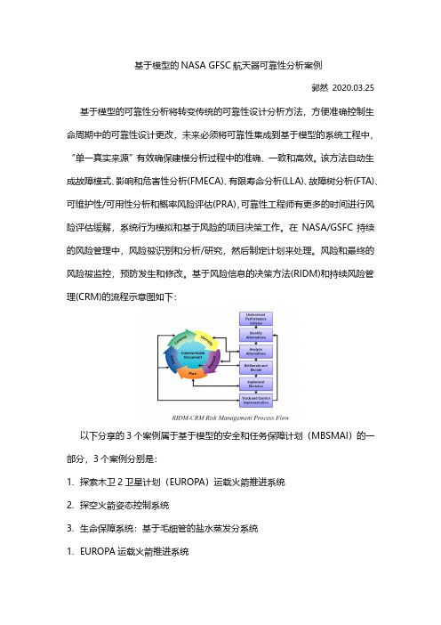
基于模型的NASA GFSC航天器可靠性分析案例郭然2020.03.25 基于模型的可靠性分析将转变传统的可靠性设计分析方法,方便准确控制生命周期中的可靠性设计更改,未来必须将可靠性集成到基于模型的系统工程中,“单一真实来源”有效确保建模分析过程中的准确、一致和高效。
该方法自动生成故障模式、影响和危害性分析(FMECA)、有限寿命分析(LLA)、故障树分析(FTA)、可维护性/可用性分析和概率风险评估(PRA),可靠性工程师有更多的时间进行风险评估缓解,系统行为模拟和基于风险的项目决策工作。
在NASA/GSFC持续的风险管理中,风险被识别和分析/研究,然后制定计划来处理。
风险和最终的风险被监控,预防发生和修改。
基于风险信息的决策方法(RIDM)和持续风险管理(CRM)的流程示意图如下:以下分享的3个案例属于基于模型的安全和任务保障计划(MBSMAI)的一部分,3个案例分别是:1.探索木卫2卫星计划(EUROPA)运载火箭推进系统2.探空火箭姿态控制系统3.生命保障系统:基于毛细管的盐水蒸发分系统1.EUROPA运载火箭推进系统Europa推进系统模型由9个主要功能框图组成,1个在系统级,8个在子系统级。
例如,推进剂隔离燃料组件模型由13个组件组成,其中8个组件的功能和流程是手动定义的,其余5个组件的建模使用了MADe预定义组件。
这13个组件中的每一个组件都由一个故障图支持,该故障图包含所有潜在的故障模式、影响、原因以及检测和补偿因素。
电力故障机制和原因是自动填充作为默认的故障图;机械故障机制需要手动添加到库组件故障图中(一次操作可保存重用)。
推进系统模块组成系统功能流框图故障机理图故障树图自动生成FMECA报告2.探空火箭姿态控制系统探空火箭姿态控制系统模型由4个主要功能框图组成,一个在系统级,两个在子系统,一个在部件级。
CASC模型由12个组件组成,其中5个组件的功能和流程是新定义的,其余7个组件使用MADe 模型库中已有的预定义组件进行建模。
- 1、下载文档前请自行甄别文档内容的完整性,平台不提供额外的编辑、内容补充、找答案等附加服务。
- 2、"仅部分预览"的文档,不可在线预览部分如存在完整性等问题,可反馈申请退款(可完整预览的文档不适用该条件!)。
- 3、如文档侵犯您的权益,请联系客服反馈,我们会尽快为您处理(人工客服工作时间:9:00-18:30)。
NASA-STD-7009NASA TECHNICALSTANDARDApproved: 07-11-2008 National Aeronautics and Space AdministrationWashington, DC 20546-0001Expiration Date: 07-10-2013Superseding NASA-STD-(I)-7009 STANDARD FOR MODELS AND SIMULATIONSMEASUREMENT SYSTEM IDENTIFICATION:NOT MEASUREMENT SENSITIVEDOCUMENT HISTORY LOGApproval Date Description Status DocumentRevisionInterim 12-01-2006 Interim Baseline ReleaseRelease Baseline 07-11-2008 BaselineFOREWORDThis standard is published by the National Aeronautics and Space Administration (NASA) to provide uniform engineering and technical requirements for processes, procedures, practices, and methods that have been endorsed as standard for models and simulations (M&S) developed and used in NASA programs and projects, including requirements for selection, application, and design criteria of an item. This standard was specifically developed to respond to Action 4 from the 2004 report “A Renewed Commitment to Excellence,” with consideration also given to related findings as identified in the Columbia Accident Investigation Board (CAIB) Report.This standard is approved for use by NASA Headquarters and NASA Centers, including Component Facilities.This standard covers the development and operation (or execution) of M&S, as well as the analysis and presentation of the results from M&S. This also includes the proper training ofM&S practitioners and the identification of recommended practices, while ensuring thecredibility of the results from M&S is assessed and properly conveyed to those making critical decisions.Requests for information, corrections, or additions to this standard should be submitted via “Feedback” in the NASA Technical Standards System at .Original Signed By July 11, 2008Michael G. Ryschkewitsch Approval DateNASA Chief EngineerSECTION TABLE OF CONTENTSPAGEDOCUMENT HISTORY LOG (2)FOREWORD (3)TABLE OF CONTENTS (4)LIST OF FIGURES (6)LIST OF TABLES (6)1. SCOPE (7)1.1 Purpose (7)1.2 Applicability (8)1.3 Focus (9)2. APPLICABLEDOCUMENTS (9)2.1 General (9)2.2 GovernmentDocuments (9)2.3 Non-GovernmentDocuments (9)2.4 Order of Precedence (9)3. ACRONYMSANDDEFINITIONS (10)3.1 Acronyms and Abbreviations (10)3.2 Definitions (10)4. REQUIREMENTS (14)4.1 Programmatics (15)4.2 Models (16)4.3 Simulations and Analyses (18)4.4 Verification, Validation, and Uncertainty Quantification (19)4.5 Identification and Use of Recommended Practices (21)4.6 Training (22)4.7 Assessing the Credibility of M&S Results (23)4.8 Reporting Results to Decision Makers (24)5.GUIDANCE (26)5.1 ReferenceDocuments (26)5.2 KeyWordListing (28)TABLE OF CONTENTS, continuedSECTION PAGE Appendix A M&S Risk Assessment (29)Appendix B Credibility Assessment Scale (31)Appendix C Compliance Matrix (51)LIST OF FIGURESFigure Title Page 1 Sample M&S Risk Assessment Matrix (30)Scale (31)2 CredibilityAssessmentWeights (45)3 Subfactor4 Bar Chart and Radar Plot for Factor Scores (47)Illustration (49)Flag5 DeficiencyFlagIllustration (50)6 Exceedance7 Sufficiency Thresholds and Color Coding on Bar Chart and RadarPlot for Factor Scores (50)LIST OF TABLESTable Title Page1 Key Aspects of Credibility Assessment Levels (33)2 Level Definitions for Evidence Subfactors in the M&SDevelopment Category (37)3 Level Definitions for Evidence Subfactors in the M&S OperationsCategory (40)4 Level Definitions for Factors in the Supporting Evidence Category.. 425 Level Definitions for the Technical Review Subfactors (44)6 Roll-up of Subfactor Scores to Factor Score (46)7 Roll-up of Factor Scores to Overall Score (47)8 Roll-up of Factor Scores to Category Score (48)STANDARD FOR MODELS AND SIMULATIONS1. SCOPE1.1 PurposeThis standard was developed in response to Action 4 from the 2004 report “A Renewed Commitment to Excellence,” which stated the following:“Develop a standard for the development, documentation, and operation of models and simulationsa.Identify best practices to ensure that knowledge of operations is captured in the userinterfaces (e.g., users are not able to enter parameters that are out of bounds),b.Develop process for tool verification and validation, certification, reverification,revalidation, and recertification based on operational data and trending,c.Develop standard for documentation, configuration management, and qualityassurance,d.Identify any training or certification requirements to ensure proper operationalcapabilities,e.Provide a plan for tool management, maintenance, and obsolescence consistent withmodeling/simulation environments and the aging or changing of the modeledplatform or system,f.Develop a process for user feedback when results appear unrealistic or defyexplanation.”Subsequently, in 2006, the NASA Chief Engineer provided the following further guidance:g.“Include a standard method to assess the credibility of the models and simulationspresented to the decision maker when making critical decisions (i.e., decisions thateffect human safety or mission success) using results from models and simulations,h.Assure that the credibility of models and simulations meet the project requirements.” Each of the requirements and recommendations in this standard can be traced to one or more of the eight objectives listed above. The traceability matrix of the requirements in this standard to the eight objectives can be found online upon accessing this standard at URL; refer to “Requirements Traceability Matrix.” Some of these objectives are met by recommendations rather than by requirements as a result of either (a) the practical impossibility of satisfying the requirement in all cases, or (b) further guidance received from NASA Headquarters.These eight objectives are encapsulated in the overall goal for this standard, which is to ensure that the credibility of the results from M&S is properly conveyed to those making critical decisions. Critical decisions based on M&S results, as defined by this standard, are those technical decisions related to design, development, manufacturing, ground, or flight operations that may impact human safety or program/project-defined mission success criteria. The intent is to reduce the risks associated with critical decisions. This standard covers the development and operation (or execution) of M&S as well as the processes of analysis and presentation of the results from the M&S.This standard addresses aspects of M&S that are common across NASA activities. Discipline-specific details of M&S should be addressed in future documents, such as Recommended Practices (usually entitled “Handbooks” in the NASA document hierarchy), and are not included in this standard.The scope of this standard covers the development and maintenance of models, the operation of simulations, the analysis of the results, training, recommended practices, the assessment of the M&S credibility, and the reporting of the M&S results. Some of the key features of this standard are requirements and recommendations for verification, validation, uncertainty quantification, training, credibility assessment, and reporting to decision makers; also included are the cross-cutting areas of documentation and configuration management (CM).The requirements/recommendations in sections 4.7 and 4.8 are the culmination of the standard. The requirements/recommendations in sections 4.1 – 4.6 are intended to support the requirements in sections 4.7 and 4.8. This is accomplished by ensuring that sufficient details of the M&S process along with intermediate results are available to support the requirements in sections 4.7 and 4.8 and to respond to in-depth queries by the decision maker. Appendix A provides guidance for assessing the risk of using M&S in engineering decisions. Appendix B provides details related to some of the requirements/recommendations in sections 4.7 and 4.8. Appendix C contains a template for a compliance matrix.1.2ApplicabilityThis standard applies to M&S used by NASA and its contractors for critical decisions in design, development, manufacturing, ground operations, and flight operations. (Guidance for determining which particular M&S are in scope is provided in section 4.1 and Appendix A.) This standard also applies to use of legacy as well as commercial-off-the-shelf (COTS), government-off-the-shelf (GOTS), and modified-off-the-shelf (MOTS) M&S to support critical decisions. Generally, for such M&S, particular attention may need to be paid to defining the limits of operation and to verification, validation, and uncertainty quantification. Programs and projects are encouraged to apply this standard to M&S, if the M&S results may impact future critical decisions.This standard does not apply to M&S that are embedded in control software, emulation software, and stimulation environments. However, Center implementation plans for NPR 7150.2, NASA Software Engineering Requirements, should specifically cover embedded M&S, and addresssuch M&S-specific issues as numerical accuracy, uncertainty analysis, sensitivity analysis, M&S verification, and M&S validation.This standard may be cited in contract, program, and other Agency documents as a technical requirement. Requirements are indicated by the word “shall”; explanatory or guidance text is indicated in italics.1.2.1Tailoring for application to a specific program or project shall be formally documented as part of program or project requirements and approved by the Technical Authority.1.3 FocusIn general, standards may focus on engineering/technical requirements, processes, procedures, practices, or methods. This standard focuses on requirements and recommendations. Hence, this standard specifies what shall or should be done; it does not prescribe how the requirements are to be met, nor does it specify who is the responsible party for complying with the requirements.DOCUMENTS2. APPLICABLE2.1 GeneralThe documents listed in this section contain provisions that constitute requirements of this standard as cited in the text of section 4.2.1.1The latest issuances of cited documents shall be used unless otherwise approved by the assigned Technical Authority.The applicable documents are accessible via the NASA Online Directives Information System at and the NASA Technical Standards System at, or may be obtained directly from the Standards Developing Organizations or other document distributors.2.2Government DocumentsNone.2.3Non-Government DocumentsNone.2.4 Order of PrecedenceThis document establishes requirements and guidance for models and simulations but does not supersede nor waive established Agency requirements found in other documentation.2.4.1Conflicts between this standard and other requirements documents shall be resolved by the responsible Technical Authority.3. ACRONYMS AND DEFINITIONS3.1Acronyms and AbbreviationsAIAA American Institute of Aeronautics and AstronauticsASME American Society of Mechanical EngineersCAIB Columbia Accident Investigation BoardScaleCAS CredibilityAssessmentManagementCM ConfigurationCOTS Commercial-Off-The-ShelfCPIAC Chemical Propulsion Information Analysis CenterDMSO Defense Modeling and Simulation OfficeGOTS Government-Off-The-ShelfIEEE Institute of Electrical and Electronics EngineersISG Implementation Study GroupOrganization for StandardizationISO InternationalJANNAF Joint Army-Navy-NASA-Air ForceSimulationsandM&S ModelsMOTS Modified-Off-The-ShelfNASA National Aeronautics and Space AdministrationNASTRAN NASA Structural AnalysisNPR NASA Procedural RequirementsPMBA Primary Mirror Backplane AssemblyReq. RequirementGuideRPG RecommendedPracticesInteroperability Standards OrganizationSISO SimulationSTD StandardValidationV&V Verification&Validation, and AccreditationVV&A Verification,3.2 DefinitionsThe definitions listed below are those used in this document. Wherever possible, these definitions have been taken from official NASA documents. In some cases, after reviewing definitions of interest in the International Organization for Standardization (ISO), the Defense Modeling and Simulation Office (DMSO), professional society publications, and English language dictionaries, some of these definitions were taken or adapted from these sources to achieve the goal and objectives stated in section 1.1. Some definitions may have alternate meanings in other documents and disciplines.Abstraction: The process of selecting the essential aspects of a reference system to be represented in a model or simulation while ignoring those aspects that are not relevant to the purpose of the model or simulation (adapted from Fidelity ISG Glossary, Vol. 3.0).Accuracy: The difference between a parameter or variable (or a set of parameters or variables) within a model, simulation, or experiment and the true value or the assumed true value.Analysis: Any post-processing or interpretation of the individual values, arrays, files of data, or suites of executions resulting from a simulation.Artifact: Any tangible product that is produced by the project team, i.e., requirements documents, help systems, code, executables, test documentation, test results, diagrams, etc.Calibration: The process of adjusting numerical or modeling parameters in the model to improve agreement with a referent.Model: The numerical representation of the mathematical model.ComputationalConceptualModel: The collection of abstractions, assumptions, and descriptions of physical processes representing the behavior of the reality of interest from which the mathe-matical model or validation experiments can be constructed (adapted from ASME V&V 10).Configuration Management (CM): A management discipline applied over the product's life cycle to provide visibility into and to control changes to performance, functional, and physical characteristics (NPR 7120.5D, NASA Space Flight Program and Project Management Requirements).Credibility: The quality to elicit belief or trust in M&S results.Decision: Those technical decisions related to design, development,Criticalmanufacturing, ground, or flight operations that may impact human safety or mission success, as measured by program/project-defined criteria.Emulation: The use of an M&S to imitate another system, so that the M&S behaves like or appears to be the other system.Endorsement: A formal assurance that a product, process, or service conforms to specified characteristics. (Examples of endorsement include “accreditation”—the official acceptance of a model or simulation and its associated data to use for a specific purpose—and “certification,” which is similar to accreditation, but often applies to a class of purposes or a general domain and generally implies an independent and/or third-party certifier.)HumanSafety: The condition of being protected from death, permanently disabling injury, severe injury, and several occupational illnesses. In the NASA context this refers to safety of the public, astronauts, pilots and the NASA workforce (adapted from NPR 8000.4 and the NASA Safety Hierarchy).Limits of Operation: The boundary of the set of parameters for which an M&S result is acceptable based on the program/project-required outcomes of verification, validation, and uncertainty quantification.Model: The mathematical equations, boundary values, initial conditions,Mathematicaland modeling data needed to describe the conceptual model (ASME V&V 10).Mission Success Criteria: Standards against which the program or project will be deemed a success. Mission success criteria may be both qualitative and quantitative, and may cover mission cost, schedule, and performance results as well as actual mission outcomes (NPR 7120.5C, NASA Program and Project Management Processes and Requirements).Model: A description or representation of a system, entity, phenomena, or process (adapted from Banks, J., ed. (1998). Handbook of Simulation. New York: John Wiley & Sons).(A model may be constructed from multiple sub-models; the sub-models and the integrated sub-models are all considered models. Likewise, any data that goes into a model is considered part of the model. A model of a model (commonly called a metamodel), e.g., a response surface constructed from the results of M&S, is considered a model).Referent: Data, information, knowledge, or theory against which simulation results can be compared (adapted from ASME V&V 10).Risk: The combination of the probability that a program or project will experience an undesired event and the consequences, impact, or severity of the undesired event, if it were to occur. Both the probability and consequences may have associated uncertainties (adapted from NPR 7120.5D).SensitivityAnalysis: The study of how the variation in the output of a model can be apportioned to different sources of variation in the model input and parameters (adapted from Saltelli and others, 2000).Simulation: The imitation of the characteristics of a system, entity, phenomena, or process using a computational model.Stimulation: The description of a type of simulation whereby artificially generated signals are provided to real equipment in order to trigger it to produce the result required for verification of a real-world system, training, maintenance, or for research and development.Subject Matter Expert: An individual having education, training, or experience in a particular technical or operational discipline, system, or process and who participates in an aspect of M&S requiring his/her expertise.Tailoring: The documentation and approval of the adaptation of the processes and approach to complying with requirements according to the purpose, complexity, and scope of a NASA program or project. (NPR 7123.1A, NASA Systems Engineering Processes and Requirements).Uncertainty: (1) The estimated amount or percentage by which an observed or calculated value may differ from the true value (The American Heritage Dictionary of the English Language, 4th ed.). (2) A broad and general term used to describe an imperfect state of knowledge or a variability resulting from a variety of factors including, but not limited to, lack of knowledge, applicability of information, physical variation, randomness or stochastic behavior, indeterminacy, judgment, and approximation (adapted from NPR 8715.3B, NASA General Safety Program Requirements).Quantification: The process of identifying all relevant sources ofUncertaintyuncertainties, characterizing them in all models, experiments, and comparisons of M&S results and experiments, and of quantifying uncertainties in all relevant inputs and outputs of the simulation or experiment.Validation: The process of determining the degree to which a model or a simulation is an accurate representation of the real world from the perspective of the intended uses of the model or the simulation.Verification: The process of determining that a computational model accurately represents the underlying mathematical model and its solution from the perspective of the intended uses of M&S.Waiver: A documented authorization intentionally releasing a program or project from meeting a requirement (NPR 7120.5D). Deviations and exceptions are considered special cases of waivers.4. REQUIREMENTSThis standard establishes a minimum set of requirements and recommendations for the use of M&S to support critical decisions.For decisions based on results from M&S, the risk assumed by the decision maker is often misestimated due to inadequate assessment of uncertainties within M&S development, verification, validation, execution, analysis, and reporting. This standard establishes practicesto enable a more accurate assessment of this risk by making M&S credibility more apparent tothe decision maker. This standard emphasizes documentation and CM of M&S to enforce transparency, repeatability, and traceability; and it requires that key M&S personnel receive appropriate training.The requirements and recommendations are generic in nature because of their broad applicability to all types of M&S. Implementation details of the M&S requirements should be addressed in discipline-specific Recommended Practices, project/program management plans, etc.The following organizational structure is employed in this standard:4.1 Programmatics4.2 Models4.3 Simulations and Analyses4.4 Verification, Validation, and Uncertainty Quantification4.5 Identification and Use of Recommended Practices4.6 Training4.7 Assessing the Credibility of M&S Results4.8 Reporting Results to Decision MakersIn many instances, the modeling, simulation, and analysis activities are interwoven, particularly during the development, verification, and validation phases. This standard is intended to be inclusive of all these possibilities.Many of the requirements in this standard require documentation. With the exception of the documentation required for reports to decision makers (section 4.8), this documentation may consist of a reference to other existing documents, such as a journal article, a technical report, or a program/project document, provided that all the required details are contained in the referenced document(s).4.1 ProgrammaticsCritical decisions that are based entirely or partially on M&S are usually made within the context of a program or project. Program and project management have the responsibility to identify and document the parties responsible for complying with the requirements in this standard.The actual person identified by program and project management to fulfill the role of the “responsible party” in specific requirements will likely vary depending upon the context of the requirement; for example, the responsible party might be the lead, or another supporting person associated with the model development, operation, analysis, and/or reporting of results to decision makers.Program and project management in collaboration with the Technical Authority have the responsibility to identify and document the extent and level of formality of documentation needed to meet the documentation requirements in this standard. Some requirements, in particular, 4.1.5,4.2.6, 4.2.8, 4.3.6, 4.4.1, 4.4.2, 4.4.4, 4.4.5, 4.4.6, 4.4.7, 4.4.8, and 4.4.9, are to be interpreted as meaning that the activity in question is not required per se, but that whatever was done is to be documented, and if nothing was done a clear statement to that effect is to be documented. Program and project management in collaboration with the Technical Authority have the responsibility to identify and document the critical decisions to be addressed with M&S and to determine which M&S are in scope.The latter determination should be based upon the risk posed by the anticipated use of the M&S. Appendix A describes a representative M&S risk assessment matrix for this purpose.Furthermore, the Technical Authority has the particular responsibility to assure appropriate outcomes of Req. 4.1.3.The responsible party performs the following:Req. 4.1.1 – Shall document the risk assessment for any M&S used in critical decisions,Req. 4.1.2 – Shall identify and document those M&S that are in scope.Req. 4.1.3 – Shall define the objectives and requirements for M&S products including the following:a. The acceptance criteria for M&S products, including any endorsement for theM&S.b. The rationale for the weights used for the subfactors in the CredibilityAssessment Scale (see Appendix B.4).c. I ntended use.d. M etrics (programmatic and technical).e. V erification, validation, and uncertainty quantification (see section 4.4).f. Reporting of M&S information for critical decisions (see section 4.8).g.CM (artifacts, timeframe, processes) of M&S.(The acceptance criteria in 4.1.3 (a) includes specification of what constitutes a favorable comparison for the Verification Evidence, Validation Evidence, Input Pedigree Evidence, andUse History level definitions in the Credibility Assessment Scale (see Appendix B).)Req. 4.1.4– Shall develop a plan (including identifying the responsible organization(s)) for the acquisition, development, operation, maintenance, and/or retirement of the M&S. Req. 4.1.5 – Shall document any technical reviews performed in the areas of Verification, Validation, Input Pedigree, Results Uncertainty, and Results Robustness (seeAppendix B).Req. 4.1.6 – Shall document M&S waiver processes.Req. 4.1.7 – Shall document the extent to which an M&S effort exhibits the characteristics of work product management, process definition, process measurement, processcontrol, process change, and continuous improvement, including CM and M&Ssupport and maintenance.4.2 ModelsThe processes of developing conceptual, mathematical, or computational models are all considered to be modeling activities. Empirically adjusting the results of a simulation in an attempt to improve correlation is considered a modeling activity.For models, the responsible party performs the following:Req. 4.2.1 – Shall document the assumptions and abstractions underlying the conceptual model, including their rationales.Req. 4.2.2 – Shall document the basic structure and mathematics of the model (e.g., reality modeled, equations solved, behaviors modeled, conceptual models).(For COTS, GOTS, MOTS, and legacy M&S, some of the documentation required in 4.2.1 and 4.2.2 may be available in published user guides; a reference to the user guides will suffice for this part of the documentation.)Req. 4.2.3 – Shall document data sets and any supporting software used in model development and input preparation.Req. 4.2.4 – Shall document required units and vector coordinate frames (where applicable) for all input/output variables in the M&S.Req. 4.2.5 – Shall document the limits of operation of models.Req. 4.2.6 – Shall document any methods of uncertainty quantification and the uncertainty in any data used to develop the model or incorporated into the model.Req. 4.2.7 – Shall document guidance on proper use of the model.(Guidance on proper use of a model includes descriptions of appropriate practices for set-up, execution, and analysis of results.)Req. 4.2.8 – Shall document any parameter calibrations and the domain of calibration.Req. 4.2.9 – Shall document updates of models (e.g., solution adjustment, change ofparameters, calibration, and test cases) and assign unique version identifier,description, and the justification for the updates.Req. 4.2.10 – Shall document obsolescence criteria and obsolescence date of the model. (Obsolescence refers to situations where changes to the real system invalidate the model—see item (e) of Diaz Action #4.)Req. 4.2.11 – Shall provide a feedback mechanism for users to report unusual results to model developers or maintainers.Req. 4.2.12 – Shall maintain (conceptual, mathematical, and computational) models and associated documentation in a controlled CM system.Req. 4.2.13 – Shall maintain the data sets and supporting software referenced in Req. 4.2.3 and the associated documentation in a controlled CM system.。