rscr使用说明
艾格尔化工泵说明书

泵能承受的最大压力是在关闭出口阀状态下总压头的1.5倍
介质的蒸汽压力必须大于绝对总吸入压头(吸入端压力加上吸程)与吸入管路的压力损失(包括汽蚀余量损失)的 差值(至少1m水柱)
泵不包括任何防止介质回流的阀之类的装置, 也不包括电机止动装置。
5
工作原理
液力原理 : 泵包含一个在静止泵体内旋转的叶轮。径向排出 (向上,内部导流)。叶轮的旋转使叶轮中心处产生低压
□ 拆卸管路时:请留出足够的时时间间让使介残质余从的泵介体质中排彻出底泵排壳空并使
大气注入空腔。
□ 开始维修之前, 必须对泵进行清洗。
执行拆泵工作的第一步是将液力端从电机端 □ 请不要将清洗完的液体随处排放。
卸下
□ 在拆泵之前, 确保电机已经断接并且不会突然起动。
卸下连接螺栓(POS.1)
□ 在检查泵之前, 手边需要备一份O形圈, 以备安装工作结束
ROUTE_TMR_MANUAL_CHN_Rev.1
Pag.4
最大连续工作温度(按水计算)是由所选择的材质(标注在泵体铭牌上)决定的。
80℃(176℉)
WR
110℃(230℉)
GF
环境温度范围与所选材质有关(在标识牌上)有规定。
0-40℃(14-104℉)
WR
′-20-40℃(-4-104℉)
GF
三相电机的绕组 (例如电压 (a) 230-400 V; (b) 400-690 V)如果是接低电压(230 for (a); 400 for (b))必须是三角形接法。
如果接高电压(400 for (a); 690 for (b)),则应该是星形接法。
星/三角起动适用于功率大于 7,5 kW (10 HP)的电机和频繁的短时间运行功率大于15 kW (20 HP)的电机。 这同时是为了满足保护泵的需要。
rscr使用说明
rscr使用说明rscr使用说明1、简介rscr是一个强大的文档管理系统,可用于组织、存储和分享各种类型的文档。
本说明将详细介绍rscr的功能和使用方法,以帮助用户更好地利用该系统。
2、登录与账户管理2.1 注册新账户在rscr的登录页面,“注册新账户”按钮,填写必要信息并创建一个新的账户。
2.2 登录输入已注册的用户名和密码,“登录”按钮进行登录。
2.3 密码重置若忘记密码,“忘记密码”按钮,按照提示重置密码并登录。
3、文档与3.1 文档登录后,页面上的“文档”按钮,选择要的文档文件,可同时多个文件。
3.2 文档找到需要的文档,文档名称或图标,在弹出的窗口中选择选项,即可文件到本地。
4、文档搜索与筛选4.1 关键词搜索在系统的搜索框中输入关键词,“搜索”按钮执行搜索操作,搜索结果将显示符合关键词的文档列表。
4.2 文档筛选使用筛选功能可根据文档的属性进行快速筛选,如文档类型、作者、创建日期等。
选择相应的筛选条件后,“筛选”按钮进行筛选操作。
5、文档分享与协作5.1 分享文档选择需要分享的文档,文档名称或图标,在弹出的窗口中选择“分享”选项,并设置分享的权限和有效期。
5.2 协作编辑文档名称或图标,进入文档详情页面,“编辑”按钮,多个用户可同时编辑文档并实时保存修改。
6、文档管理与权限控制6.1 文档分类用户可自定义文档的分类,通过创建文件夹或标签,并将文档归类到相应的文件夹或标签下,方便管理和检索。
6.2 权限设置用户可根据需要设置文档的访问权限,如只允许特定用户或团队查看、编辑文档等。
7、其他功能7.1 历史版本软件会自动保存文档的历史版本,用户可通过版本管理功能查看、恢复以前的文档版本。
7.2 回收站删除文档后,文档会被移动到回收站,用户可在回收站中找到并恢复或永久删除文档。
附件:附件1:rscr使用示例文档:pdf附件2:rscr用户指南:pdf法律名词及注释:1、版权:著作权法所赋予原创作品的独占权利,禁止未经作者许可的复制、修改、发布等行为。
智能UPS在线降压变压器SRT5KRMTF说明书
Safety MessagesRead the instructions carefully to become familiar with the equipment before attempting to install, operate, service or maintain the transformer. The following special messages may appear throughout this manual or on the equipment to warn of potential hazards or to call attention to information that clarifies or simplifies a procedure.The addition of this symbol to a Danger or Warning safety label indicates that an electrical hazard existswhich will result in personal injury if the instructions are not followed.The addition of this symbol to a Warning or Caution product safety label indicates that a hazard exists thatcan result in injury and product damage if the instructions are not followed.NOTICENOTICE used to address practices not related to physical injury. The safety alert symbol is not used with this signal word.Safety Information• Adhere to all national and local electrical codes.• All wiring must be performed by a qualified electrician.• Changes and modifications to this unit not expressly approved by APC could void the warranty.• This transformer is intended for indoor use only.• Do not operate this transformer in direct sunlight, in contact with fluids, or where there is excessive dust or humidity.• Be sure the air vents on the transformer are not blocked. Allow adequate space for proper ventilation.• For a transformer with a factory installed power cord, connect the transformer power cable directly to an output receptacle of the UPS. Do not use surge protectors or extension cords.• The equipment is heavy. Always practice safe lifting techniques adequate for the weight of the equipment.•Always install the transformer directly above the UPS in the rack-mount configurations. The UPS must be installed below the transformer.• Always install peripheral equipment above the UPS in rack-mount configurations.• Additional safety information can be found in the Safety Guide supplied with this unit.Electrical safety• 230 V models only: In order to maintain compliance with the EMC directive for products sold in Europe, output cords attached to the transformer must not exceed 10 meters in length.• The protective earth conductor for the transformer carries the leakage current from the load devices (computer equipment). An insulated ground conductor is to be installed as part of the branch circuit that supplies the transformer.The conductor must have the same size and insulation material as the grounded and ungrounded branch circuit supplyconductors. The conductor will typically be green and with or without a yellow stripe.• The UPS input ground conductor must be properly bonded to protective earth at the service panel.• If the UPS input power is supplied by a separately derived system, the ground conductor must be properly bonded at the supply transformer or motor generator set.General information• The model and serial numbers are located on a small, rear panel label. For some models, an additional label is located on the chassis under the front bezel.• Recycle the package materials or save them for reuse.FCC Class A radio frequency warningThis equipment has been tested and found to comply with the limits for a Class A digital device, pursuant to part 15 of the FCC Rules. These limits are intended to provide reasonable protection against harmful interference when theequipment is operated in a commercial environment. This equipment generates, uses, and can radiate radio frequency energy and, if not installed and used in accordance with the instruction manual, may cause harmful interference to radio communications. Operation of this equipment in a residential area is likely to cause harmful interference in which case the user will be required to correct the interference at his own expense.Product InformationThe Smart-UPS™ SRT transformer is intended for use as an isolation transformer. This transformer can also function asa step down transformer.The transformer can be installed in a standard 19-inch rack with the supplied rail kit.Package ContentsInspect the contents upon receipt. Notify the carrier and dealer if the unit is damaged.2Smart-UPS On-Line Step-Down Transformer SRT5KRMTFSmart-UPS On-Line Step-Down Transformer SRT5KRMTF 3SpecificationsFor additional specifications refer to the APC by Schneider Electric web site, .EnvironmentalPhysicalElectricalOperation above the input voltage range may cause equipment damage.Operation below the input voltage range may cause overload or automatic shutdown. When connecting directly to a branch circuit, check that the line voltage is within specifications. When connecting to the UPS, check that the line voltage into the UPS is within specifications before transferring to bypass mode.TemperatureOperating 0º to 40º C (32º to 104º F)Storage -15º to 45º C (5º to 113º F)Maximum ElevationOperating 0 - 3,000 m (0 - 10,000 ft)Storage 0 - 15,000 m (50,000 ft)Humidity0% to 95% relative humidity, non-condensingProtection Class IP 20 ratingInstallationWith Line Cord Nominal Input Voltage (Vac)208 Vac Nominal Output Voltage (Vac)120 Vac Input Voltage Range (Vac)185 - 230 Vac *Input Current Rating24 A Line Frequency (Hz)50/60 Hz Efficiency90-95%Maximum Input Power5000 VA Maximum Output Power (VA)4500 VA*For continuous operation below Vin = 205 Vac, the output load must be reduced to limit the maximum input current to the amount specified above. Continuous operation above the maximum specified input current may cause the unit to overheat and shut down. Contact APC by Schneider Electric for additional information.Input Power Distribution3 ft cord with L6-30P Output Power Distribution (2) 15 A circuits with (4) 5-20R and (2) 15 A circuits with (2) 5-20RRack InstallationInstall railsFor details on support rail installation, refer to the instructions in the rail kit.Install transformer4Smart-UPS On-Line Step-Down Transformer SRT5KRMTFSmart-UPS On-Line Step-Down Transformer SRT5KRMTF 5Connecting Equipment and Power to the TransformerRear panelStart-Up1.Check that all power is turned OFF.2.Connect all load equipment to the transformer receptacles.Note: Each receptacle group is protected by a circuit breaker. A colored label identifies each circuit and the corresponding breaker.3.Switch the transformer input circuit breaker ON.4.Turn on output circuit breakers as needed.5.Turn on all connected equipment.Output 15 A Max.Overload protector Output 15 A Max.Output 15 A Max. Overload protectorOutput 15 A Max. Input Overload protectorOverload protector Overload protector Input power cordServiceIf the unit requires service, do not return it to the dealer. Follow these steps:1.Review the Troubleshooting section of the manual to eliminate common problems.2.If the problem persists, contact APC Customer Support through the APC web site, .a.Note the model number and serial number and the date of purchase. The model and serialnumbers are located on the rear panel of the unit and are available through the LCD display onselect models.b.Call APC Support and a technician will attempt to solve the problem over the phone. If this isnot possible, the technician will issue a Returned Material Authorization Number (RMA#).c.If the unit is under warranty, the repairs are free.d.Service procedures and returns may vary internationally. Refer to the APC web site for countryspecific instructions.3.Pack the unit properly to avoid damage in transit. Never use foam beads for packaging. Damage sustained intransit is not covered under warranty.a.Note: When shipping within the United States, or to the United States alwaysDISCONNECT ONE UPS BATTERY before shipping in compliance with U.S.Department of Transportation (DOT) and IATA regulations. The internal batteries mayremain in the UPS.b.Batteries may remain connected in the XBP during shipment. Not all units utilize XLBPs.4.Write the RMA# provided by Customer Support on the outside of the package.5.Return the unit by insured, prepaid carrier to the address provided by Customer Support.6Smart-UPS On-Line Step-Down Transformer SRT5KRMTFLimited Factory WarrantySchneider Electric IT Corporation (SEIT), warrants its products to be free from defects in materials and workmanship for a period of two (2) years from the date of purchase. The SEIT obligation under this warranty is limited to repairing or replacing, at its own sole option, any such defective products.Repair or replacement of a defective product or part thereof does not extend the original warranty period.This warranty applies only to the original purchaser who must have properly registered the product within 10 days of purchase. Products may be registered online at .SEIT shall not be liable under the warranty if its testing and examination disclose that the alleged defect in the product does not exist or was caused by end user or any third person misuse, negligence, improper installation, testing,operation or use of the product contrary to SEIT recommendations of specifications. Further, SEIT shall not be liable for defects resulting from: 1) unauthorized attempts to repair or modify the product, 2) incorrect or inadequate electrical voltage or connection, 3) inappropriate on site operation conditions, 4) Acts of God, 5) exposure to the elements, or 6) theft. In no event shall SEIT have any liability under this warranty for any product where the serial number has been altered, defaced, or removed.EXCEPT AS SET FORTH ABOVE, THERE ARE NO WARRANTIES, EXPRESS OR IMPLIED, BYOPERATION OF LAW OR OTHERWISE, APPLICABLE TO PRODUCTS SOLD, SERVICED ORFURNISHED UNDER THIS AGREEMENT OR IN CONNECTION HEREWITH.SEIT DISCLAIMS ALL IMPLIED WARRANTIES OF MERCHANTABILITY, SATISFACTION ANDFITNESS FOR A PARTICULAR PURPOSE.SEIT EXPRESS WARRANTIES WILL NOT BE ENLARGED, DIMINISHED, OR AFFECTED BY AND NO OBLIGATION OR LIABILITY WILL ARISE OUT OF, SEIT RENDERING OF TECHNICAL OR OTHER ADVICE OR SERVICE IN CONNECTION WITH THE PRODUCTS.THE FOREGOING WARRANTIES AND REMEDIES ARE EXCLUSIVE AND IN LIEU OF ALL OTHER WARRANTIES AND REMEDIES. THE WARRANTIES SET FORTH ABOVE CONSTITUTE SEIT’S SOLE LIABILITY AND PURCHASER EXCLUSIVE REMEDY FOR ANY BREACH OF SUCH WARRANTIES.SEIT WARRANTIES EXTEND ONLY TO ORIGINAL PURCHASER AND ARE NOT EXTENDED TO ANY THIRD PARTIES.IN NO EVENT SHALL SEIT, ITS OFFICERS, DIRECTORS, AFFILIATES OR EMPLOYEES BE LIABLE FOR ANY FORM OF INDIRECT, SPECIAL, CONSEQUENTIAL OR PUNITIVE DAMAGES, ARISING OUT OF THE USE, SERVICE OR INSTALLATION OF THE PRODUCTS, WHETHER SUCH DAMAGES ARISE IN CONTRACT OR TORT, IRRESPECTIVE OF FAULT, NEGLIGENCE OR STRICT LIABILITY OR WHETHER SEIT HAS BEEN ADVISED IN ADVANCE OF THE POSSIBILITY OF SUCH DAMAGES.SPECIFICALLY, SEIT IS NOT LIABLE FOR ANY COSTS, SUCH AS LOST PROFITS OR REVENUE, WHETHER DIRECT OR INDIRECT, LOSS OF EQUIPMENT, LOSS OF USE OF EQUIPMENT, LOSS OF SOFTWARE, LOSS OF DATA, COSTS OF SUBSTITUANTS, CLAIMS BY THIRD PARTIES, OROTHERWISE.NOTHING IN THIS LIMITED WARRANTY SHALL SEEK TO EXCLUDE OR LIMIT SEIT LIABILITY FOR DEATH OR PERSONAL INJURY RESULTING FROM ITS NEGLIGENCE OR ITS FRAUDULENT MISREPRESENTATION OF TO THE EXTENT THAT IT CANNOT BE EXCLUDED OR LIMITED BY APPLICABLE LAW.To obtain service under warranty you must obtain a Returned Material Authorization (RMA) number from customer support. Customers with warranty claims issues may access the SEIT worldwide customer support network through the APC web site: . Select your country from the country selection drop down menu. Open the Support tab at the top of the web page to obtain information for customer support in your region. Products must be returned with transportation charges prepaid and must be accompanied by a brief description of the problem encountered and proof of date and place of purchase.Smart-UPS On-Line Step-Down Transformer SRT5KRMTF7© 2015 APC by Schneider Electric. APC, the APC logo, Smart-UPS and PowerChute are owned bySchneider Electric Industries S.A.S. or their affiliated companies. All other trademarks are property oftheir respective owners.EN 990-5473A3/2015APC by Schneider Electric Worldwide Customer SupportCustomer support for this or any other APC by Schneider Electric product is available at no charge in any of the following ways:•Visit the APC by Schneider Electric web site, to access documents in the APC Knowledge Base and to submit customer support requests.– (Corporate Headquarters)Connect to localized APC by Schneider Electric web site for specific countries, each of which provides customer support information.–/support/Global support searching APC Knowledge Base and using e-support.•Contact the APC by Schneider Electric Customer Support Center by telephone or e-mail.–Local, country specific centers: go to /support/contact for contact information.–For information on how to obtain local customer support, contact the APC by Schneider Electric representative or other distributor from whom you purchased your APC by Schneider Electric product.。
Hunter SRR遥控器 用户说明书

SRR遥控器用户安装使用手册 美国HUNTER公司出品 北京绿友时代园林机械有限公司中国总代理 简介与安装说明 简介............................................................................2 SRR遥控器组成...................................................................2 连接智能接口(SmartPort™).....................................................3 安装SRR遥控器的智能接口.........................................................3 典型安装........................................................................4 室内安装接收器..................................................................4 室外安装接收器..................................................................4 获得最大的遥控距离..............................................................5 延长智能接口(SmartPort™)的连接线.............................................5 发射器和接收器使用的准备 发射器使用的准备................................................................5 安装发射器的电池................................................................6 遥控改变激活站点的运行时间......................................................6 改变发射器的地址................................................................6 改变最大站点号..................................................................7 接收器使用的准备................................................................7 改变接收器的地址................................................................8 发射器和接收器的操作 用SRR遥控器激活控制系统的一个站点...............................................8 关于遥控距离的说明..............................................................9 故障排除指南....................................................................9 性能参数.......................................................................10 有了SRR遥控器,当保养和维修灌溉系统时,不必亲自到控制器跟前进行手动灌溉操作;一个工人就可快速简便地进行冬天防冻处理,而无须再用两个工人,;在需要手动启动或关闭灌溉系统时,通过遥控即可实现,而无需再到控制器控制器安装的位置。
Sun Remote System Control (RSC) 2.2 使用者指南说明书
Sun™ Remote System Control(RSC) 2.2使用者指南用於所支援的Sun工作群組伺服器Sun Microsystems, Inc.901 San Antonio RoadPalo Alto, CA 94303-4900 U.S.A.650-960-1300文件號碼:816-3236-102002年3月,修訂版A關於本文件的意見請傳送至:*******************Copyright 2002 Sun Microsystems, Inc., 901 San Antonio Road, Palo Alto, CA 94303-4900 U.S.A. 版權所有。
本產品或文件按照限制其使用、複製、分發和反編譯的授權許可進行分發。
未經Sun及其授權許可頒發機構的書面授權,不得以任何方式、任何形式複製本產品或本文件的任何部分。
協力廠商軟體,包括字型技術,由Sun供應商提供許可和版權。
本產品的某些部分從Berkeley BSD系統衍生而來,經University of California許可授權。
UNIX是在美國和其他國家的註冊商標,經X/Open Company, Ltd. 獨家許可授權。
Sun、Sun Microsystems、Sun標誌、AnswerBook2、、Java、OpenBoot、Solstice、SunVTS、SunExpress、Solaris、Sun Enterprise和Sun Fire是Sun Microsystems, Inc. 在美國和其他國家的商標、註冊商標或服務標記。
所有的SPARC商標都按授權許可使用,是SPARC International, Inc. 在美國和其他國家的商標或註冊商標。
具有SPARC商標的產品都基於Sun Microsystems, Inc. 開發的架構。
OPEN LOOK和Sun™圖形使用者介面是Sun Microsystems, Inc. 為其用戶和其授權許可持有㆟開發的。
RSC使用手册

RSC 电子期刊检索栏位
-8-
RSC 使用手册
此为 RSC 电子期刊检索画面,使用者可以选择单本或多本期刊同时进行检索(要选 择多本期刊请按住 Ctrl 不放,并利用鼠标器点选期刊名称即可),之后再照着上面的栏 位,依序填入查询条件,如年代、页数、卷期、篇名、作者、摘要或全文关键字…等 等。
Online 1364-5528 1471-7107 1460-4760 1460-4779 1460-4787 1474-9181
1364-548
1460-47444444 1744-15799999
1466-8033 1477-9234
1364-5498 1463-9270
1364-5544 1464-0333 1364-5501 1473-0189
RSC 网站的右方中间,列举出一些较常为使用者利用的资源,因此使用者 可以在此区域找到有关 RSC 出版图书、组织简介、教育训练等等相关资源。
-7-
RSC 使用手册
(三)、查询功能
此章节主要针对 RSC 电子期刊之查询功能作一个深入的说明,期望能够通过 这样的方式,让使用者能够轻易地掌握查询之技巧与功能,进而快速且精确的找 到最适切的信息。
在下一个章节,将针对 RSC 网站功能,由浅入深,并以图解的方式,让使用 者可以通过本手册按图所冀,快速熟悉并充份利用 RSC 所提供之化学专业资源。
-4-
RSC 使用手册
(二)、一般功能
RSC 于 2005 年 5 月完成主机转移与启用新版网站,因此在使用介面与功能 上,都有别于以往的改变,包括 RSC 对化学资源的整合、产品的查询以及资料的 呈现等等。在「一般功能」单元中,主要针对 RSC 新介面的介绍及说明,希望能 够帮助使用者快速掌握 RSC 的网站功能与资源。
海洛斯操作手册(说明书)
HIROSS恒温恒湿机房精密空调操作手册HIMOD系列北京****科技有限公司技术部2009年01月01日目录第一章HIMOD系列海洛斯空调概述 (2)型号多 (3)控制技术先进 (3)制冷系统 (3)送风系统 (3)加湿系统 (3)加热系统 (4)1.7其它 (4)第二章HIMOD系列海洛斯空调型号含义 (4)第三章有关空调的一些资料 (5)气流组织方式(详见下图) (5)盖板纽开启方式(详见下图) (5)空调重量(单位:Kg) (5)机组尺寸及维护空间 (6)第四章制冷循环管路示意图 (7)风冷却(A型) (7)水冷却(W型) (8)双冷源(D型) (9)单系统(C型) (10)双系统(C型) (10)第五章调速风机调速接线示意图 (11)第六章MICROF ACE概述 (12)概述 (12)面板简介液晶显示屏 (13)液晶显示屏介绍 (13)第七章MICROF ACE面板的操作 (13)第八章控制器的使用 (14)控制器(HIROMATIC)概述 (14)控制器的操作 (15)菜单结构 (17)第九章日常维护及特殊维护 (18)日常维护 (18)特殊维护 (19)第十章常见报警及处理 (20)低压报警 (20)高压报警 (21)加湿报警 (21)失风报警 (21)电加热过热报警 (22)显示器发黑 (22)空调不制冷 (22)附录1:参数列表 (22)附录2:报警内容列表 (26)附录3:各菜单项含义: (28)第一章HIMOD系列海洛斯空调概述HIMOD系列海洛斯空调(HIMOD空调)是当今世界上最先进的机房专用恒温恒湿机房专用精密空调。
随着IT业的突飞猛进的发展,各种布局、面积差别很大的机房如雨后春笋般纷纷出现了,使用环境也不一而同。
为适应各种不同要求的机房,新开发的海洛斯HIMOD系列空调应运而生。
她是在保留她的前一代产品HIRANGE系列机房空调的优点,又应用了当今世界上提高了的制冷技术及制冷部件制造工艺,使用当今最先进的模块化设计理念生产出来的高科技机房空调产品。
S-R6 Inverter Remote Control用户手册说明书
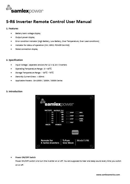
S-R6 Inverter Remote Control User Manual1. Features•Battery bank voltage display•Output power display•Error condition indicator (High Battery, Low Battery, Over Temperature, Over Load conditions)•Indicator for status of operation (INV, GRID, POWER SAVING)•Failed connection display2. Specification•Input Voltage : separate versions for 12 V & 24 V inverters•Operating Temperature Range : 0 – 40℃•Storage Temperature Range : - 30℃ - 70℃•Stand-By Current Draw : < 80mA•Applicable Models : SA-1000K / 2000K / 3000K Series3. Introduction•Power ON/OFF SwitchPower ON/OFF switch is to turn the inverter on or off. You are supposed to hear one beep sound every time you switch on or off.•Battery voltage indicator “BATTERY”This bar chart controls a light that will move up and down as the battery voltage changes. Ideally, the voltage should remain in the green area of the bar chart.If the voltage goes into the red area at the top and bottom of the graph, inverter may shut down.•Output power indicator “OUTPUT (%) POWER”The AC load watt chart indicates the power drawn from the inverter by the load. Ideally, the watt indicator should remain in the green & orange area of the bar chart.If the OUTPUT POWER indicator is up to the red area of the bar, the light will flash and the inverter will shut down for inverter safety.•Over voltage protection indicator “OVP”The over voltage protection indicator is to indicate that the inverter has shut down because its input voltage is above 12 /24 VDC.•Under voltage protection indicator “UVP”The under voltage protection indicator is to indicate that the inverter has shut down because its input voltage is below 12 / 24 VDC.•Over temperature protection indicator “OTP”The over temperature protection indicator is to indicate that the inverter has shut down because of overheating. The over temp indicator will be OFF when the inverter cools down.•Overload protection indicator “OLP”The overload protection indicator is to indicate that the inverter has shut down because of short circuit or overloadproblems.•“INV” indicatorThe INV indicator is to indicate that the inverter is ready.•GRID indicatorThe GRID indicator is to indicate that the inverter is in Pass Through Mode & transferring Grid power to the load(Applicable to the versions with Transfer Relay).•PWR.SAV. IndicatorPower saving functions are described below:•Reverse Over-ride (ROF) and Ignition Lockout FunctionsThe Recreation Vehicle Industries Association (RVIA) of America and some American states require that when a vehicle is in motion, the TV monitor should be switched off if it is in the view of the driver. Sometimes, the TV monitor is used in conjunction with a camera to enable the driver to view the area at the back of the vehicle when the vehicle is being reversed. The TV monitor should normally remain off (if it is in view of the driver) and should power on only when the gear is shifted to “reverse”. When the gear is shifted to “reverse”, a micro-switch in the reversing mechanism in the vehicle generates a “+” battery voltage signal that can be used to switch on the TV monitor. This is termed as “Reverse Over-ride Function (ROF)”. If the TV monitor is powered from the inverter, “ROF” function will enable to switch on the inverter when the vehicle is reversed and “+” battery voltage signal is fed to the Remote.Also, some low power circuits in a vehicle are energized when the ignition switch is turned to the “Accessory” position to provide “+” battery voltage power to low power devices like radio / CD player etc (the vehicle is not running in this position and hence, high power devices should not be powered as the starter battery will get drained and the vehicle may not start).When the ignition switch is turned to the “Accessory” position, a “+” battery voltage line is available for actuating the required devices. As the inverter is a high power consuming device, it should be switched off when the ignition switch is turned to the “Accessory” position. Hence, the “Ignition Lockout” function is utilized to switch off the inverter when “+”battery voltage signal is fed to the Remote on activation of the “Accessories” circuitIn the back of the Remote Control, a ¼” male quick disconnect terminal is provided to switch on or switch off the inverter by feeding “+” battery voltage signal. A jumper is provided in the Remote Control (The jumper is accessible after opening the bottom cover of the remote control) to select either “ROF” function or “Ignition Lockout” function. The Remote Control comes preset in “ROF” position✓In the preset condition of “ROF”, when the “+” battery voltage signal from the reversing gear system is fed to the ¼” male disconnect terminal, the inverter is switched on. When “+” battery voltage signal is removed, theinverter is switched off.✓When the alternate “Ignition Lockout” function is selected (by changing the position of the internal jumper), the inverter shuts down when “+” battery voltage signal from the “Accessories” circuit is applied and switcheson when the “+” battery voltage is removed.The wire used for feeding the “+” battery voltage signal to the ¼” connector for the ROF or Ignition Lockout functions should have a 0.5A fuse in series for protection.•Selecting ROF or Ignition Lockout FunctionsJumper JP1 is placed inside the remote control and is used to select either Reverse Override Function or Ignition lockout Function (open the back cover for access to the jumper JP-1).✓JP1 jumper “Short” - Reverse Override Function*✓JP1 jumper “Open” – Ignition Lockout Function*Please note that the default mode is Short.•Connect the wire RJ-11 to the remote port in front of the panel.✓ Ignition Lockout function – The ignition lockout function is to turn the Inverter OFF when the auxiliary inputwiring is connected to the ACC, and “+” battery voltage signal is applied.✓ Reverse Override Function – The Reverse Override Function is to turn the inverter ON when the auxiliaryinput wiring is connected to the reverse gear Shift, and “+” battery voltage signal is applied.• Installation Procedure1.Refer to the drawing (see Figure 2) for hole and cutout dimensions. 2.Use the cable between S-R6 remote and the inverter. 3. Switch the inverter to REMO position.Figure 24. Drawings of S-R6 Remote Control Cables。
RSC-406数位式比例同步控制器产品说明书

盤面型RSC-406使用說明書浙江麗水謙勝機電有限公司浙江麗水水閣工業區綠穀大道306-2號TEL: FAX:068目錄1.前言~1~1.前言... ... ... ... ... ... ... ... ... ... ... ... ... ... ... ... ... ... ... ... ... ... ... ... ... .... ... ... . (2)2.產品特點介紹... ... ... ... ... ... ... ... ... ... ... ... ... ... ... ... ... ... ... ... ... .... ... .... (3)3.產品檢查… … ..33-1 數位式同步控制器外觀... ... ... ... ... ... ... ... ... ... ... ... ... ... ... ... ... ....... (3)3-2 控制器外觀尺 (4)3-3 控制器面板顯示及操作說明... ... ... ... ... ... ... ... ... ... .... ... ... ... ..... ... (4)3-3-1 LED 燈號說明… … … … … … … … … … … … … … … … … … … … …… .53-3-2 按鍵操作說...5首先感謝您選用由本公司所開發的 RSC-406 數位式比例同步控制器。
為了充分地發揮RSC-406 的功能,及確保使用者的安全,請詳閱本操作手冊。
當您使用中出現任何疑點而本手冊無法提供您解決方案時,請您與本公司連絡,我們將竭誠為您服務。
並請您繼續采用本公司的產品。
4.安裝... ... ... ... ... ... ... ... ... ... ... ... ... ... ... ... ... ... ... ... ... ... ... ... ... ... .... ... .. (6)!注意4-1 使用環境... ... ... ... ... ... ... ... ... ... ... ... ... ... ... ... ... ... ... ... ... ....... ... .. (6)4-2 控制器後端護弓,端子安裝方式及盤面安裝尺寸... ... ... ... ... ... ... ... .. (6)5.配線... ... ... ... ... ... ... ... ... ... ... ... ... ... ... ... ... ... ... ... ... ... ...... ... ... ... ..... (7)5-1 端子功能說明… … … … … … … … … … … … … … … … … … … … … … ......75-2 標准配線圖… … … … … … … … … … … … … … … … … … … … … … … …..85-3 控制回路配線圖… … … … … … … … … … … … … … … … … … … … … .. (9)5-4 變位回授控制配線圖… … … … … … … … … … … … … … … … … … … … .10 5-5 手動/自動切換控制配線圖... ... ... ... ... ... ... ... ... ... ... ... ... ... ... ... ... . (11)6.參數說明... ... ... ... ... ... ... ... ... ... ... ... ... ... ... ... ... ... ... ... ... ... ... ... ... ... .. (11)7.電子差速器的運用… … … … … … … … … … … … … … … … … … … … … ...… ..138.比例K值及線速K值的設定... ... ... ... ... ... ... ... ... ... ... ... ... ... ... ... ... . (14)8-1 比例 K 值的設定… … … … … … … … … … … … … … … … … … … … … … .14 8-2 線速 K 值的設定… … … … … … … … … … … … … … … … … … … … ...… ..149.控制模式設定(參數1)… … … … … … … … … … … … … … … … … … … … .… ..1510.參數一覽表... ... ... ... ... ... ... ... ... ... ... ... ... ... ... ... ... ... ... ... ... ... ... .... .... (15)11.異常故障顯示與對策... ... ... ... ... ... ... ... ... ... ... ... ... ... ... ... ... ... ... ... ..... (1)612.試車注意事項… … … … … … … … … … … … … … … … … … … … … … …...… ..17附錄:外圍設備之選用... ... ... ... ... ... ... ... ... ... ... ... ... ... ... ... ... ... ... ... ... ... . (18)A. 譯碼器… … … … … … … … … … … … … … … … … … … … …… … … … … .18B. 變位檢出器… … … … … … … … … … … … … … … … … … … … …... ... .. (18)不可在送電中實施配線,或拆裝 RSC-406 的連接端子。
磁力搅拌器

Magnetic Stirrer磁力搅拌器User Manual说明书请在使用前仔细阅读本说明书,并且遵守所有操作安全提示!Contents内容Contents内容 (1)Preface前言 (2)Warranty质保期 (2)1. Safety Instructions安全提示 (3)2. Proper Use适用范围 (3)3. Inspection检查 (6)3.1 Receiving Inspection验收 (6)3.2 Listing of Items零件清单 (6)4. Trial run调试 (7)5. Control and Display控制及显示 (7)5.1 Control elements控制器 (7)5.2 Display显示 (8)6. Operating Modes操作示例 (8)6.1 Magnetic stirrer with hot plate operation磁力搅拌器操作说明(不带加热板) (8)6.2 Hot Plate without stirring operation电热板操作说明(不带搅拌器) (9)6.3 Digital type operation 数显型操作说明 (9)7. Faults错误 (12)8. Maintenance and Cleaning保养及清洁维护 (13)9. Storage and transportation存放及运输 (13)10. Main technical parameters主要技术参数 (14)11. Working condition工作条件 (14)-1-Preface前言Thank you for purchasing our products: Hotplate / Magnetic Stirrer. Users should read this Manual carefully, follow the instructions and procedures, and beware of all the cautions when using this instrument.感谢您购买我们的产品:电热板/磁力搅拌器。
汉森尔-接锐脉冲雷达物位计用户操作手册rev2.0

警告静电防护措施本仪表中由于含有易感受静电的电子器件。
因此对其内部的电路板或元器件进行拆卸、以及安装等操作时,均应采取适当有效的静电防护措施,并请按下述原则进行。
1.必须拆除仪表的供电电源2.对印刷电路板或其内部元件进行接触、拆卸、安装、以及调整前,操作人员应佩戴防静电环或者采取其它安全可靠的方式接地,确保静电快速顺畅的泄放。
3.印刷电路板必须置于导电包装袋或其它的导电容器中进行运输、存储,直到现场安装时,才允许将其从静电防护包中取出。
被拆换的印制电路板必须立即放进具有静电防护功能的容器内,不可随意放置以备运输、存储。
运输存储仪表采用纸箱或木箱包装,在搬运时小心转运,不允许野蛮装卸,存放地点应符合防雨防潮、且不受机械震动或冲击等。
开箱验货仪表拆箱后严格按装箱清单验货,若发现有错误、缺货或破损等现象,请立即与我公司或当地代理联系。
仪表装调1.详细阅读说明书,严格按相关要求进行安装和调试;2.确保仪表可靠接地;3.仪表接线完成后,出线口密封性良好,护线管无积水现象发生;4.仪表调试完成后,旋紧表盖。
环保本仪器的包装物符合环保要求,拆箱后请用户交当地回收机构。
目录1概述 (4)1.1原理 (4)1.2特点和优势 (4)1.3使用频率 (5)2尺寸 (6)2.1外壳尺寸 (6)2.2仪表尺寸 (6)3技术特性 (11)4安装指南 (13)4.1开箱与验货 (13)4.2安装 (13)4.3测量条件 (22)5电气连接 (25)5.1供电电压 (25)5.2连接电缆和安装 (25)5.3屏蔽电缆和接地 (25)5.4电缆参数 (26)5.5输出参数 (26)5.6接线方式 (27)5.7防爆连接 (28)6仪表调试种类 (30)6.1仪表液晶显示单元 (30)6.2仪表远程液晶显示单元(罐旁显示单元) (31)6.3上位机调试 (31)6.4HART手操器(中控室液晶显示单元) (32)7.1参数架构 (33)7.2基本设定方法 (34)7.3主界面介绍 (35)7.4回波快捷查看界面 (35)7.5【快速设置】菜单 (37)7.6【基本设置】菜单 (39)7.7【显示设置】菜单 (39)7.8【系统设置】菜单 (40)7.9【线性化】菜单 (40)7.10其它菜单说明 (42)8调试验收确认 (42)附件1:常见故障处理 (43)附表2:常见物质介电常数 (44)1概述1.1原理雷达物位计是基于时间行程原理的无线电波测距系统。
RSC Bio Solutions RSC EnviroLogic HF 68 HP SDS说明书
发布日期: 02-十一月-2016修订日期 14-八月-2017SDS 编号: -企业名称: RSC Bio Solutions 产品名称: RSC EnviroLogic HF 68 HP版本号: 02化学品安全技术说明书按照GB/T 16483、GB/T 17519编制。
1. 化学品及企业标识RSC EnviroLogic HF 68 HP 商品名称ELHP68Part No.RSC Bio Solutions 制造商或供应商600 Radiator RoadIndian Trail, NC 28079地址美国无资料。
联系人电子邮件无资料。
联系电话电话号码:704-684-6100传真:704-257-8996应急电话EMERGENCY PH NO:1-800-661-3558推荐用途及限制用途无资料。
推荐用途02-十一月-2016发布日期14-八月-2017修订日期02-十一月-2016替代日期2. 危险性概述紧急情况概述无资料。
危险类别未被分类。
标签要素无。
象形图警示词无。
危险性说明混合物不符合分类的标准。
防范说明预防措施遵守良好工业卫生习惯。
事故响应操作后洗手。
安全储存远离禁忌物保存。
废弃处置根据当地管理部门的要求对废弃物和残余物进行处理。
产品在正常的使用、储存和运输条件下是稳定的和非活性的。
无异常的火灾或爆炸危险。
物理和化学危险持续的吸入可能是有害的。
预计较低的食入危害。
直接接触可引起眼部暂时刺激。
健康危害产品不被分类为环境有害物质。
然而,这不排除大量的和经常的泄漏物可能对环境产生有害影响或损害。
环境危害补充信息无。
3. 成分/组成信息混合物物质/混合物浓度(%)CAS 号化学名称178603-64-050 - < 60Synthetic Biodegradable Base Oil 40 - < 50低于报告水平的其它成分4. 急救措施移至空气新鲜处。
如果症状持续或恶化,联络医生。
rsr音响说明书

r sr音响说明书篇一:7条不为人知的苹果音响使用小知识7条不为人知的苹果音响使用小知识随着苹果产品越来越受中国消费者喜爱,为苹果产品专门配套的苹果音响用户也越来越多,下面,笔者就以目前在中国销售最火热的R SR苹果音响为例,给大家介绍一下音响使用小知识。
1、目前市场上苹果音响主要以9p in的L ight ni ng闪电接口为主,i Phon e5\5s\5c等都使用最新接口,30pi n的苹果设备已全部停产;2、苹果音响基本上以基座式、便携式为主,可以在办公室、客厅、床头等多个地方使用,完全支持苹果设备音乐播放、充电等;3、主要功能,iPo d(苹果)功能、B T(蓝牙)功能、AUX(外接音频)功能、FM(收音机)功能、AL ARM(闹钟)功能,这是五项最主要的功能;4、初次使用配对,P air配对,这是任何一款苹果音响的蓝牙初次配对,一般默认密码为0000,也有特殊为8888;5、PROG电台自动调谐,常按此键3秒(本文来自:.bdFq Y.cO M千叶帆文摘:rs r音响说明书),在FM收音机模式下,可以自动搜索出20个信号最强的电台,这个功能非常好用; 6、关闭电源,目前的苹果音响都是即插即用式,不用时记得关闭电源,尤其在没有显示屏的情况下,让您误以为已关闭其实电流仍然在使用;7、认清M FI认证,任何苹果音响都必须获得MFI认证,无认证的苹果音响会损害到苹果设备的使用受用,因为苹果是不支持盗版软硬件的。
CR CRI CRN安装和操作说明书

7.0 启动 注意:在水泵未充满液体和彻底排空气之前,不 要启动水泵。
注意排气孔的方向,小心确保溢出 的水不要伤及人员,也不对水泵或 者其他部件造成损坏。 在热水应用场合,特别要小心以免 存在受热水烫伤的危险。 请参照 3~4 页的说明。 CR,CRI,CRN 1 至 5, CRI,CRN 8 和 16: 对于这些水泵,建议在启动期间,打开旁通 阀,旁通阀将泵的吸入侧和排出侧连接在一起, 这样就使得灌水过程更为容易。当运转平稳后, 可以关闭旁通阀。如果泵送的液体含有空气,建 议让旁通阀一直开着。 图7
CR, CRI, CRN 1,3,5
图3 CR, CRN 8,16
以“米水头”计的最大吸入口扬程“H”可用下式进行 计算:
H=Pb×10.2-NPSH-Hf-Hv-Hs Pb = 以bar计的大气压力(大气压力可取 1bar),在
闭式系统中,Pb为以bar计的系统压力。 NPSH = 以“米水头”计的气蚀余量值,(在技术样本
上的气蚀余量曲线上,读出对应于泵所输送的
最大流量时的数值)。
Hf = 吸入管的摩擦阻力损失,以米水头计。 Hv = 蒸汽压力,以米水头计,参见 15 页的图E,其
中tm=液体温度。 Hs = 安全余量=0.5 米水头 如果计算所得的 H 值为正值,则水泵可在最大的吸入扬 程“H”(m)下工作。 如果计算所得的 H 值为负值,则水泵工作时需要一个最 小的吸入扬程“H”(m)。在运行期间,必定有一个压 力等于计算所得的“H”值。 例:
安装管道时,应避免管道产 生气堵,特别是在水泵的吸 入管道上。
安装时,如果存在以下情 形:
排出管总是从泵开始向 下倾斜, 存在虹吸管影响的危 险, 有必要防止不干净的液 体回流时 必须在水泵的附近安装一 个真空阀。
在线自动堆焊机操作说明书
在线自动堆焊机 操作说明书目 录1、前言 (2)2、安全注意事项 (3)3、技术指标 (3)4、接线方式 (3)5、面板功能 (4)6、侧板功能 (5)7、操作与使用 (6)8、设备安装 (13)9、工作异常的检查要点 (9)2前 言为了顺应不断提高的焊接技术和焊接工艺,我们及时地推出了这一款高性能、高性价比的工业级自动直线行走机构。
本机构选用进口名牌电机及控制器件,用(脉宽调制技术)、电流反馈等综合技术。
使之有效保证焊接质量。
本机专为水泥机械,电力设备,冶炼机械等行业高要求施工对象设计,并能满足多种形体要求,同时还可进行摆动行走。
总体来说本机构具有以下几大优异性能:1、直线行走稳定、噪声小,重复行走精度高。
2、可随意设置行走距离。
3、可实现多种模式行走。
4、快速行走和低速行走同等精度。
5、支枪机构可以自动调节。
让用户即减少了设备的投入,又提高了生产效率,体现了极高的性价比。
非常感谢您使用利玛赫式在线自动堆焊机。
为了能让您正确掌握利玛赫式在线自动堆焊机的操作方法和安全使用。
请务必在使用前仔细阅读本说明书。
一、 本产品主机保修期为一年。
其余相关附件及易损件不在保修范围之内。
二、 保修期内、非人为损坏、非自然灾害引起的损坏可免费保修。
其余的均要收取成本工时费。
三、 客户不得自行拆卸、改装及更换零件,否则可能会带来严重的后果。
对于上述因素产生的任何后果,本所不予承担责任。
3一、安全注意事项1、利玛赫式在线自动堆焊机应放置在有利通风的地方,后面板与周围物品或墙壁应相隔50cm以上,以利控制箱排放热量。
可燃物与机构距离不得少于5m。
2、利玛赫式在线自动堆焊机及控制箱周围可燃物保持足够的距离,必须确认电弧产生的火花及烟尘绝对不会直接掉落在控制箱触摸屏上,也绝对不会到达可燃物品。
3、利玛赫式在线自动堆焊机应可靠接地,并按安全要求正确穿戴防护服装﹑绝缘手套及安全鞋。
4、单相电源必须经单相闸刀开关接入行走机构控制箱。
rscr使用说明

二.软件功能
1.按给定的定转子铁心尺寸、槽形尺寸和绕组数据进行电磁性能核算;
2.按给定的定转子铁心尺寸、槽形尺寸和绕组导线数据由微机选定绕组线规并进行电磁性能计算;
3.给定铁心长度、每槽导体数的初值、步长,终值可进行多方案计算比较;
4.对同一机座号不同铁心长度的多个规格同时进行计算,以便比较,适用于系列化设计;
5.可计算在不同负荷率下的损耗和性能指标:
负荷率KKW:1.0,0.9,0.75,0.6,0.5,0.4
KW—输出功率P1—输入功率Eff—效率
Pf—功率因数Tm—最大转矩倍数I1—定子电流
Sn—转差率Pfw—机械损耗Pfe—铁耗
Pcu1—定子铜耗Pcu2—转子铜(铝)耗Pcgm—总损耗
6.输入数据共分四类:
(1).AA数据:基本不变数据,如频率、电压……等;
(2).BB数据:随不同规格而变的数据,如功率、极数、槽数……等;
(3).CC数据:随不同方案而变的数据,如槽形尺寸、铁心长度、每槽线数、绕组线规以及控制计算和打印的变量;
(4).DD数据:长短铁心连算几只规格时需要输入的数据。
7.计算结果输出(根据需要可随便选择):
*29. Le1—双笼双端环时为下笼导条伸出铁心两边长,单笼时取0;
*30. hr1—双笼双端环时为下端环高度,单笼取0。
CC数据
1.bs1—见图一;
2.bs2—bs2>0为圆底槽,bs2<0为平底槽,bs2=2Rs,见图一;
3.hs12—见图一;
4.br1—见图二;
5.br2—见图二;
6.br3—见图二;
13. jj 14. djj 15. mm 16. Dmm
rscr使用说明
rscr使用说明在当今数字化的时代,各种新技术和工具层出不穷,为我们的生活和工作带来了极大的便利。
Rscr 作为一款实用的工具,其功能强大但使用起来却并不复杂。
接下来,就让我为您详细介绍一下 rscr 的使用方法。
首先,在您准备使用 rscr 之前,请确保您已经从正规的渠道获取了该软件,并成功安装到您的设备上。
无论是电脑、平板还是手机,rscr 都能为您提供良好的使用体验。
打开 rscr 之后,您会看到一个简洁清晰的界面。
界面的布局通常会分为几个主要区域,比如功能菜单区、操作区和显示区。
在功能菜单区,您可以找到各种各样的选项,这些选项涵盖了 rscr 的主要功能。
比如说,如果您需要进行数据处理,那么您可以点击“数据处理”选项,然后在弹出的子菜单中选择具体的数据处理操作,如数据清洗、数据分析、数据转换等。
当您选择了具体的功能之后,操作区就会相应地出现对应的操作界面和指引。
以数据清洗为例,操作区可能会有数据导入的按钮,您可以通过点击这个按钮将需要清洗的数据文件导入到 rscr 中。
导入数据之后,rscr 会自动对数据进行初步的分析,并为您提供一些清洗的建议和选项,比如去除重复数据、纠正错误数据、补充缺失数据等。
您只需要根据自己的需求,勾选相应的选项,然后点击“开始清洗”按钮,rscr 就会按照您的设定进行数据清洗操作。
在数据清洗的过程中,显示区会实时显示清洗的进度和结果。
您可以随时查看清洗的数据是否符合您的预期,如果发现有问题,您可以随时停止清洗操作,并对清洗的选项进行调整。
除了数据处理功能,rscr 还具有文件管理的功能。
如果您需要对文件进行分类、整理、备份或者删除等操作,您可以在功能菜单区选择“文件管理”选项。
在文件管理的操作界面中,您可以看到您设备上的所有文件和文件夹,并可以通过简单的点击和拖拽操作来完成各种文件管理任务。
另外,rscr 还提供了强大的搜索功能。
无论您是在寻找特定的文件、数据还是操作选项,只需要在搜索框中输入相关的关键词,rscr 就会迅速为您找到与之相关的内容。
LinkStar RCST操作手册(中文终版)

LinkStar TM RCST 安装手册Version D目录一般性安全须知避免人员遭受电击伤害更换保险须使用相同类型不要从插件终端上断开动力电缆静电放电程序谨防火灾和电击应急抢救使用通过安全核准的设备应急计划附加警告1.绪论2.参考文献3.系统图表4.LinkStar远端站构成5.推荐使用的安装工具和测试设备6.IFL标准7.安装程序8.IFL安装9.天线指向10.RCST安装11.RCST操作检测TDM误码率TDMA误码率IP Ping12.交叉极化13.发现并处理故障为有效发现并处理故障,推荐使用的设备问题识别RCST电源开启失败无卫星信标信号接收同步接收TDM信号LNB接收IFL电缆天线TDM频率和符号率接收TDM误码率信号发送同步RCST传输RCST引导参数PCR分布TDMA传输电平RCST传输误码率IP通信测试分配带宽分配CIRIP状态附录A:RCST特性RCST特性表RCST前面板功能LinkStar调制和解调表附录B:《远端站安装数据资料》表格示范附录C:RCST指示灯显示附录D:远程登陆到RCST默认地址在PC机上设定一个IP地址建立一个远程登录会议网络IP地址附录E:安装RCST使用的引导参数命令格式参数描述附录F:RCST命令一般性安全须知避免人员遭受电击伤害危险:当使用金属工具时应注意避免短路。
某些电路拥有很大的瞬时电流,短路发生时产生的火花有可能灼伤皮肤,或对眼睛造成伤害。
在进行维护、调试及检查并处理故障时,应取下全部的随身饰物,及暴露在身外的一切金属物品。
在进行设备内部维护、调试及检查并处理故障时,请关闭电源,除非该工作有带电进行的必要。
在电源接通情况下请不要移动设备上的任何部件。
在进行设备维护时,可能需要移开机盖并连接交流电源。
在进行上述过程时,必须格外小心!如果操作人员不履行安全守则,将成为死亡或重大伤害的成因。
更换保险须使用相同类型危险:在更换保险时,请选择使用相同等级及类型的保险。
多种气体检测仪培训手册PPT课件
报警级别可以通过CC-Vision软件设置和更改声、光和振动报警周期重复出现, 屏幕交替显示 “A2” 和气体浓度闪烁 图标 报警无法被确认
Look at video
重设仪器后会取消TWA和STEL值.遵从所述安全操作流程.
TWA 报警
报警级别可以通过CC-Vision软件设置和更改声、光和振动报警周期重复出现屏幕交替显示 “A2” 和气体浓度闪烁 图标报警无法被确认
Look at video
最大值菜单最大值菜单Look at video
显示氧气传感器的最大值. 数值从仪器上次重设起开始记录。 再按 “OK”键.
按住 “OK”-键3秒钟
或者按一下“+”键仪器返回测量模式最大值功能显示重设仪器读数后氧气最低浓度值和其它气体最高浓度值。用户可以使用快捷菜单查看最大值也可利用CC viபைடு நூலகம்ion软件设置最大值数值。
注意!每次测量前,需要用空气冲洗德尔格取样管活着取样探枪.测量经验: 使用新取样管时,每米平均冲洗时间为3秒钟。测量时应加上传感器响应时间。
执行测量: 将德尔格取样管或者德尔格探枪与外置泵进气口连接 执行测量完成操作: 按下松开键 LED灯闪烁绿/红灯,短暂发出鸣音 外置泵自动关闭
X-AM 1/2/5000/5600外置泵操作
注释
TWA
当 TWA分析功能激活后:按住 “OK”-键3秒钟按下 “OK ”-键一次屏幕上显示 图标 显示最大工作浓度再次按下“OK”-键显示STEL 值.或者再按一下“+”键仪器返回测量状态
菜单功能
Look at video
菜单功能
当STEL分析功能激活后:按住“OK”键三秒钟按下 “OK ”键两次屏幕上显示 图标 显示STEL 值按下 “OK ”-键或者 “+”键一次仪器返回测量
- 1、下载文档前请自行甄别文档内容的完整性,平台不提供额外的编辑、内容补充、找答案等附加服务。
- 2、"仅部分预览"的文档,不可在线预览部分如存在完整性等问题,可反馈申请退款(可完整预览的文档不适用该条件!)。
- 3、如文档侵犯您的权益,请联系客服反馈,我们会尽快为您处理(人工客服工作时间:9:00-18:30)。
负荷率KKW:1.0,0.9,0.75,0.6,0.5,0.4
KW—输出功率P1—输入功率Eff—效率
Pf—功率因数Tm—最大转矩倍数I1—定子电流
Sn—转差率Pfw—机械损耗Pfe—铁耗
Pcu1—定子铜耗Pcu2—转子铜(铝)耗Pcgm—总损耗
6.输入数据共分四类:
*29. Le1—双笼双端环时为下笼导条伸出铁心两边长,单笼时取0;
*30. hr1—双笼双端环时为下端环高度,单笼取0。
CC数据
1.bs1—见图一;
2.bs2—bs2>0为圆底槽,bs2<0为平底槽,bs2=2Rs,见图一;
3.hs12—见图一;
4.br1—见图二;
5.br2—见图二;
6.br3—见图二;
24.cd—计算控制变量,cd<0算负荷率;cd>0不算负荷率;
cd=3,AA、BB通用,只需输入CC;
cd=2,AA通用,输入BB、CC;
cd=1,输入AA、BB、C Eff 3. Pf 4. Pfw 5. L 6. Ls
7. Lt 8. a 9. ZZ 10. ZZs 11. ZZt 12. Sfo
23.Pfw—机械损耗标么值,参照已有电机的风摩耗;
24.CZn—定子绕组层数,双层取2,单层取1;
25.Srr—转子端环面积(双笼转子端环为上部端环面积);
*26. Sr1—双笼双端环的下部端环面积,单笼时取0;
*27. Jc—转子导条与槽的间隙,铸铝取0,铜条为0.20—0.30;
*28. Le—转子导条伸出铁心两边的长,铸铝时取0,铜条转子取铁心至端环距离的2倍;
7.br4—见图二;
8.hr12—见图二;
9.hr3—见图二;
10.Zc—转子槽形号,见图二;
11.L1—铁心长度初值(包括通风道长);
12.Ls—铁心长度步长,Ls>0时不作自动调整设计参数计算;
13.Lt—铁心长度终值;
14.a—定子绕组并联路数;
15.Z—定子绕组每槽导体数初值;
16.Zs—导体数步长;
湖北电机厂·技术中心·设计处
RSCR程序使用说明
〔2000年1月28日〕
一.适用范围
RSCR软件用于定子散嵌绕组的笼型转子三相异步电动机电磁计算,可用于下列各种情况:
1.各种常用的极数;
2.低电压的各种电压等级;
3.不同的频率;
4.各种绝缘等级;
5.存储五种不同磁化性能和损耗的硅钢片供计算时选用;
6.无径向、轴向通风道或有径向、轴向通风道;
WG18
H18
B25
15000
15400
15000
16350
15700
P10
2.5
2.1
1.4
1.9
1.9
5.HW—槽楔厚度;
6.Si—定子槽绝缘厚度,取单边厚;
7.Wi—导线直径1毫米及以上两边绝缘漆膜厚度,通常取0.08;
8.Lo1—定子绕组电阻率,铜:B级取0.0217,F级取0.0245;
9.Lo2—转子导条电阻率,铜:0.0217,铝:0.0434;
(5).在需要时可输出不同负荷率下的损耗和性能指标,以便对电机的运行性作综合分析。
三.输入数据
AA数据
1.f—电源频率;
2.u1—相电压;
3.Kfe—铁心叠压系数,涂漆时取0.93;
4.HP—不同磁化性能和损耗的硅钢片选择参数,
具体数据可根据需要调换,现存数据:
HP
1
2
3
4
5
硅钢片牌号
D22
D23
D32
17.Zt—导体数终值;
18.Sfo—定子绕组槽满率,给定线规时为0;由微机选线规时为控制的槽满率;
19.JJ—定子绕组导线并联根数;
20.djj—定子绕组导线直径,选定槽满率时为0;
21.mm—定子绕组导线并绕根数,同上;
22.dmm—定子绕组导线直径,同上;
23.ab—打印控制变量,ab<0打印全部数据;ab≥0打印主要数据,m=|ab|,m为长短铁心连算的规格数,这时应另外输入(m-1)组DD数据;
3.Eff—功率标准值;
4.Pf—功率因数标准值;
5.Ist—起动电流标准值;
6.Tst—起动转矩标准值;
7.Tm—最大转矩标准值;
8.Q1—定子槽数;
9.Q2—转子槽数;
10.D1—定子外径;
11.Di1—定子内径;
12.Di2—转子内径;
13.g—气隙长度;
14.Y1—定子绕组跨矩,以槽数计算,一般取短矩;
7.定子绕组为散嵌的圆铜导线或圆铝导线;
8.铸铝转子或铜排或铝排焊接转子,焊接转子导条长度可等于或大于铁心长度;
9.定子槽形为半闭口的或半开口的圆底槽或平底槽(见定子槽形图);
10.笼型转子,包括单笼或双笼(公用端环或上下笼分开端环),转子为半闭口槽、半开口槽或闭口槽。单笼7种槽形、双笼4种槽形(见转子槽形图);
15.Sk—转子斜槽度,转子斜槽宽度与定子齿距之比,无斜槽时取0,通常为1;
16.bo1—定子槽口宽;
17.hs0—定子槽口高;
18.Zs1—定子槽肩斜角度数;
19.bo2—转子槽口宽,闭口槽取负1;
20.hr0—转子槽口高,无槽口时取0;
21.Zs2—转子槽肩斜角度数,没有时取0;
22.Ps—杂散损耗标么值,铸铝:Ps=0.01—0.03极数少者取较大值;
10.dk—转子轴向通风孔直径,没有时取0;
11.nk—径向通风道数,没有时取0;
12.Lo2u—转子双笼时为上笼导条电阻率,单笼为0;
13.kt—齿铁耗系数,选定硅钢片后即已选取,此处可输入0;
14.ky—轭铁耗系数,选定硅钢片后即已选取,此处可输入0。
BB数据
1.kw—输出功率(千瓦);
2.P—极数;
11.在需要时可采用不同的齿铁耗系数或轭铁耗系数。
二.软件功能
1.按给定的定转子铁心尺寸、槽形尺寸和绕组数据进行电磁性能核算;
2.按给定的定转子铁心尺寸、槽形尺寸和绕组导线数据由微机选定绕组线规并进行电磁性能计算;
3.给定铁心长度、每槽导体数的初值、步长,终值可进行多方案计算比较;
4.对同一机座号不同铁心长度的多个规格同时进行计算,以便比较,适用于系列化设计;
(1).AA数据:基本不变数据,如频率、电压……等;
(2).BB数据:随不同规格而变的数据,如功率、极数、槽数……等;
(3).CC数据:随不同方案而变的数据,如槽形尺寸、铁心长度、每槽线数、绕组线规以及控制计算和打印的变量;
(4).DD数据:长短铁心连算几只规格时需要输入的数据。
7.计算结果输出(根据需要可随便选择):
(1).在微机终端屏幕上显示结果,设计人员可根据经验进行调整方案;
(2).计算出方案可存入文件,以便调出仔细查阅,也可永久存贮(这时要用新的文件名进行拷贝),需要时可随时打印出来;
(3).打印机输出主要参数和性能指标,以便进一步调整方案;
(4).计算出满意方案后,可打印输出计算单全部参数,以便保存;
13. jj 14. djj 15. mm 16. Dmm
注意:1.运行时数据要一次输入,以上尺寸单位均为mm;
2.带*者运行于经修改的源程序,用于铸铝单笼转子,可减少输入数据。
四.槽形尺寸
