ABB SYSTEM 800xA T530中文课程 05 - Getting Started
ABB-800XA创建用户自定义功能块面板
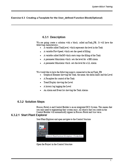
Exercise6.3Creating a Faceplate for the User_defined Function Block(Optional)6.3.1DescriptionWe are going create a solution with a block,called myTank_FB,.It will have thefollowing characteristics.∙A variable called TankLevel,which represents the level in the Tank∙A variable FlowSpeed,which sets the speed of filling∙A variable called OnOff which starts/stops the filling of the Tank∙A parameter MaxAlarm which sets the level for a HH Alarm∙A parameter MinAlarm which sets the level for a LL AlarmWe would like to have the following aspects connected to the myTank_FB∙Graphical Element showing the Tank,the name,the alarm limits and the Level∙A Faceplate for control of the Tank∙Trend Display showing the Level∙A history log logging the Level∙An Alarm and Event list showing the Tank Alarms6.3.2Solution StepsProcess Portal A and Control Builder is an an integrated DCS System.This means thatyou only need to engineering they system once.All objects that you create in theControl Builder will automatically appear in Process Portal and vice versa.6.3.2.1Start Plant ExplorerStart Plant Explorer and open navigate to the Control StuctureOpen the Project in the Control StructureIt may take a minute or two to open the Project.6.3.2.2Create a new of ProgramCreate a new Program and call it Exercise and assign a Task to the it.Process Portalgets confused if you have several applications with the same name.Be sure to select aunique name for your application.Attach it to a Task in the Controller6.3.2.3Creation of your LibraryThe next step is to create a library,so we can re-use the solution we create today inseveral projects.Create a Library called YourName DemoLib,for example demoLib.6.3.2.4Creation of myTank_FBIn the library we should create a function block type called myTank_FB.Control Builder is part of the Industrial IT,which leads to that what you create in theControl Builder is also created in the Plant Explorer.Create the functionality of the Tank Block as described below.We will later increasethe functionality.Note that you need to be in the Control Builder to makes the changes in the code.Either you switch to the Control Builder using the Tabs or you can right mouse clickon you Function Block in Plant Explorer and select Function Block Editor.Code and ParametersVariables6.3.2.5Creation of Graphic Element on myTank_FBThe next step is to create a Graphic Element on the myTank_FB type in Process Portal.We want to create a Graphic Element that shows the value of Level in a NumericDisplay and in a Bar Graph and show the name of the function block.Locate the myTank_FB in the Object Type Structure and select New Aspect.Create a new Graphic Element PG2and call it Graphic Element.Edit the element.Create the static part as followsI used the following elements1.For the tank top,bottom and body2.For the Name3.For the Bar Graph4.For the Numeric LevelIt is time to connect the elements to the process.What we are going to use it the Expression Builder.By doing this is in Object Type Structure we assign the variables relatively to the Tank Object Type.This means that the assignments will work for any tank that we create,i.e.we do not need to assign the Name and the Level to each Tank. It is done automatically.Select the Numeric and jump to the properties window.Set the parameter No1~5aswell as the blow graphic.Adjust the No.6parameter to a proper value.For the No.7parameter,jump to the Expression Editor from selecting radio buttons within the Properties Window to add dynamic value:TankLevel.Continue to add the Level to the input of the BarGraph.Connect the TextElement’s Text property to the Name of the Function Block.Save the graphic and test the behavior.Testing,while in the Graphic Editor,can be done by“View>Test Data”.Take a look in the Object Type Structure on the graphic element.6.3.2.6Creation of the your first programLets create a small application consisting of two instances of the myTank_FB and testthe functionality.We will use the Function Block Editor to write our application inProgram2Connect LibrariesThe first step we need to do is to Connect the myUserLib to our Application.Go theControl Structure and select your application.Press Connect LibrariesSelect myUserLib and press OK6.3.2.7Create the ProgramGo to Excise_No2and declare a Function Block called myTank1and assign FS1(Flow Speed1)to the input and set it to5.Repeat the procedure for another Tankcalled myTank2and use the input FS2(Flow Speed2)and set it to10.The solution is belowVariables and CodeFunction BlocksAs soon as you press Apply in the Editor Window you will get the Function Blocks in the Control Structure of Process Portal.This is what we call Integrated Engineering.Take a look in the Control Structure and you will see both Tanks.We would like to see if our programs works.Go to Simulate mode and test your program.Below is the Excise_No2in simulation modeYou can see the value of the parameters,but if you want to see the variables,for example the level you need to go down one level.You can do that my right mouse clicking on the function block and select“Online Editor”By doing that you get a view of the code inside the Function Block.In this mode you will see all variables inside the function block.Go download and go on-lineNow when you know your element is working,it is time to download and go-online.Remember to set you System Identity for you SoftController to your IP address(127.0.0.1:2for the SoftController)6.3.2.8Check that you have live dataYou can check that you have live data by looking at the Function Block aspects in theControl Structure.Locate the Exercise,Program1,select the Function Block and the tab Property Viewand select“Subscribe for live data”If you get values in the table you know that you have live data.If you do not get live data,make sure that you have started the OPC Server and thatyou have selected your PC as the provider.6.3.2.9Creation of the faceplate for myTank_FBNow we want to create a faceplate,to control our Level in the myTank_FB.First of all we need to add the code that makes is possible to stop the TankLevel in theTank.Go back to the Control Builder and edit the myTank_FB by adding an OnOff variableand use it as below.Create the FaceplateThe Faceplate is the main aspect for the faceplate.Locate the myTank_FB in theObject Type Structure and create a Faceplate PG2aspect named Faceplate.Take a look at the faceplate.At this moment it is just empty.We would like to fill it with some information and some actions buttons.The first step is to select the Config view and create two buttons On and Off to set the value of the running variable.Switch to Config View and select the Buttons tab.Click Icon/Labels to specify what icon or text you want to have on the button.The next step is to select what property we want to set.This button should set the OnOff.The third step is to set what property value we should write to the controller when we push the button.We would like to write True to the OnOff when we push the Open Button.You can also supply a tool tip.The last thing you need to do is to select in what positions the button should appear.The positions are numbered from left to right. Repeat the procedure for the Close Buttons.Call it C.The last thing you need to do is to set the position of the Button in the Faceplate.Go back to the Faceplate View and take a look at your Faceplate.Go back to the Control Structure and select the Overview Graphics on Excise_No2. Right mouse click on Tank1and select the Faceplate.Try to Open and Close the Tank.Tank2has the same functionality since we built the Faceplate on the Type.It would be nice if an operator could open the Faceplate by just clicking on the Object. It is quite easy to configure that behavior.Go back to the Object Type Structure and select the Faceplate Aspect.Right mouse click and select Properties.Select Default Aspect in the Aspect Details Tab.Go back to the Overview Graphics and click on the Tank to bring up the faceplate. Creation of a Faceplate ElementWe want to have a faceplate element in the middle of the faceplate that show a bargraph with the level.We also want to be able to set the level manually.In order to do that,we need to create a faceplate element on the myTank_FB.AFaceplate Element is an element that can accept input to the controller.Edit the faceplate element.We want to be able to click and set the level and turn the Level on and off.We are going to use the ToggleButton and the BarTie the Level to the Bar value in the Properties Window.Attach the Toggle button to the OnOff signalSave the Faceplate ElementYou need to out this faceplate element in to the faceplate.Go to the Object Type Structure and select Config View on the Faceplate and select to include the Faceplate Element in the Elements tab.Click ApplyOpen your Overview Graphics and select the Faceplate.It shall now have a nice Faceplate Element in the Faceplate.You can set the level and toggle On Off with theToggle Button.Add an indicatorWe would like to have an Indicator showing the status of the running variable.Select the ConfigView on the Faceplate in the ObjectType structure.Click in the Icons/Labels Window and supply the what shall be shown as the indicatorWe need to decide when what icon should be shown.Click in the Expression Window to supply an ExpressionIif($'.:OnOff',0,1)This expression means:Show label number0if OnOff is TRUE otherwise show label number1.Select the position to show the IndicatorOpen your Overview Graphics and select the Faceplate.It shall now have a nice Faceplate Element in the Faceplate.You can set the level and toggle On Off with the Toggle Button.6.3.2.10Creation of an Overview DisplayWe would like to have an Overview Displays that holds both of our Tanks.Go to theFunction Structure and create a new Graphic Display PG2.Right mouse click to Edit.We would,of course,like to re-use instead of creating a new Tank Element.A graphic element may be used in any graphic display.To add an element to thedisplay,select the Element Browser icon from the toolbar:All of the dynamic linking to the process data is already done.This is the power ofusing graphic elements.Therefore we are going to use the Element Explorer to selectthe Graphic Elements on our Tanks.Select myTank1and Mytank2in the Control Structure,all reusable graphic elementsare listed.This time myTank1own a graphic element named graphic element only.Select and add the graphic element in the display by several methods: -select the element and click on the edit panel-double-click the selected graphic element-drag and drop the element on to the edit panel-select the graphic element and press“Enter”.Arrange them and insert a text as a Headline.There are two modes which can be selected in the Graphics Builder:•Edit ModeThis is the default mode and allows the user to build the graphic aspect without any interactive connection to dynamic data.•Live ModeThis allows the user to view the behavior of graphic aspects with dynamic values.Please use Live mode to see result below.As you see you can have live data in the Graphics Builder.Save the Graphics.If you do not see the live data please make sure you have selected the Live Data option 6.3.2.11Add a Trend Display for myTank_FBWe would like to have a run-time trend showing the Level of the Tank.Go to theObject Type Structure and select the myTank_FB and create a Trend Display.We create Trend Display on the type.In order to get a relative path,type in“.”(youtype in a dot and the dot will be replace by the type name)for the Object.Select theFunction Block as the Aspect and the TankLevel as the property.Also set the high range to100.00Save the trend.Open your Overview Graphics and select the Trend Display.Change the time range to a minute.Configure history to log the TankLevelsWe would like to historize the TankLevel.Go to the Control Structure and create a Log Configuration Aspect on Tank1.The Log Configuration Aspect lets you define what property to log and what template to use.The template defines how to log,e.g.how often and how large of a storage each tag has.Click on the TankLevel to log it.Select the Template you would like to usePress OK and Apply.Now you TankLevel for Tank1is being Historized.Repeat the Procedure for Tank2and its TankLevel.6.3.2.12Add an Aspect Link to the Trend on the FaceplateWe want to have an Aspect Link on the faceplate to the Trend Display.Go back to theObject Type Structure and select Config View on the Faceplate and the Indicators Tab.Select the View you want the button to open.Select to use the Aspect Icon as the Icon/LabelSelect the position to be number6for all different sizes of the faceplate.Open your Overview Graphics and select the Faceplate6.3.2.13Adding Alarming to the myTank_FBConfigure the Alarm Handling for the myTank_FBIn order to get the Alarming functionality in the Controller you need to insert theAlarmEventLib into the projectConnect the Alarm&EventLib to the Application.Connect the Alarm&Event Lib to myUserLib.We will add the alarming to our myTank_FB type,which means that all our instances will get the Alarm features.Add two FunctioBlocks of the AlarmCond type,called HIHI and LOLO,to the myTank_FB.We would like to be able to change the HIHILimit and the LOLOLimit from the user interface.In order to get the correct Name displayed in the Alarm and Event List,we need to add a Name parameter and assign in the program.Declare variables and write the code as belowParametersSince we added some Parameters we needed to update the Control Logic.Download the code to the ControllerSetup AC800M/C OPC Server to collect AlarmsIf you have not configured the OPC Server to collect Alarms from your controller,please follow the steps below.(You need to do this every time you re-start yoursystem or you need to configure the OPC Server to Auto Load the configuration)Open the OPC Panel from the Start MenuType in the IP-address of your controller and press ConnectYour OPC Server is now connected to your ControllerConnect Process Portal to the OPC ServerIf you have not connected the OPC Server to Process Portal A,please follow the stepsbelow.You only need to do this onceOpen Plant Explorer and the Service Structure and locate Event collector and new aservice group object named AC800M OPC AE Collector.Add a service Provide object named AC800M OPC AE Provider in this group..Click Add and select the OPC AE Server for AC800M.Click Apply in the ServiceGroup Definition Aspect.You have now setup the Alarm Collection in Process PortalCheck the AlarmingOpen your Overview Graphics and select the Alarm List for Tank1.Note:The AlarmList was created automatically on the myTank_FB and it is configured to show alarmsonly for the selected object.You can also check the Alarms for Tank2by right mouse clicking on the Tank2andselecting the Alarm&Event List.Create an Alarm&Event List for an AreaWe would like to have an Alarm List for that shows all alarms from Tank1and Tank2.Go to Excise_No2and create an Alarm&Event listThis Alarm&Event List should show the Alarms coming from Excise_No2andbelow,i.e.myTank1and myTank2.Select the Config View on the Alarm&Event List and select“Objects and Decedents”.Press Apply.Open your Overview Graphics and select the Alarm List for Excise_No2by selectingit from the Context Menu for Excise_No2.Adding the Object DescriptionWe would like to get the Object Description from the object in the Controller to bepresented in the Alarm&Event List.To do that we need to add a parameter,called Description,on the Function Block.Goto the Control Builder and the parameter.Of course we also need to add Description variables to our instances in the ControlLogic as in blow screen dumpDownload to the controller.Now the Control Logic is prepared,but we need to do one more thing in Process Portal to get the Description available.Every time you change a Description in the controller you need to locate the Name Uploader Aspect in the Control Structure. Locate it and press upload.By doing this the descriptions on the Function Blocks inthe Controller will be transferred to Process PortalYou can bring up the Alarm&Event List,when the synchronization is done,and youshould see the object description.Include Alarm Limits in FaceplateWe would like to see the Alarm Limits in the Faceplate.Go to the Object Type Structure and select the faceplate element of myTank_FB.Select Edit.。
800xA 系统安装简易指南(工程师培训)
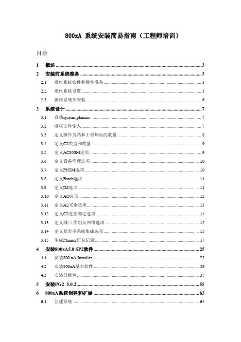
800xA 系统安装简易指南(工程师培训)目录1概述 (3)2安装前系统准备 (3)2.1操作系统软件和硬件准备 (3)2.2操作系统设置 (3)2.3操作系统预安装 (6)3系统设计 (7)3.1启动system planner (7)3.2授权文件输入 (7)3.3定义操作员站和工程师站的数量 (8)3.4定义CS类型和数量 (9)3.5定义AC800M选项 (9)3.6定义设备管理选项 (10)3.7定义PNSM选项 (10)3.8定义Batch选项 (11)3.9定义IM选项 (11)3.10定义AO选项 (12)3.11定义AS冗余选项 (13)3.12定义CS连接绑定选项 (14)3.13定义域/工作组及网络选项 (15)3.14定义是否多系统集成选项 (15)3.15生成Planner汇总记录 (17)4安装800xA5.0 SP2软件 (25)4.1安装800 xA Installer (25)4.2安装800xA基本软件 (26)4.3安装升级包 (37)5安装PG2 5.0.2 (55)6800xA系统创建和扩展 (63)6.1创建系统 (64)6.2系统扩展 (67)7导入License (69)8可能遇到的问题: (73)1 概述该文档为描述800Xa V5.0 SP2 REVB版本的安装简易指南,包括操作系统设置,安装步骤,已经安装结束后的XA系统的设置以及安装过程中应该注意的事项。
安装可以使用手动和自动两种方式。
初次安装为提高效率,可以采用自动安装完成;如果安装结束后还需要添加软件项,使用手动进行有选择的安装。
系统自动安装的基本流程为:安装前系统准备、系统设计计划、系统安装2 安装前系统准备2.1 操作系统软件和硬件准备⏹计算机硬件要求严格根据ABB800XA系统认证第3方设备文件的要求来配置高品质的服务器和工作站产品通常系统中服务器内存至少需要4G;工作站内存至少需要2GC:盘的大小:因为800xA系统中历史记录,报警记录等信息的存储默认盘为计算机操作系统的C盘。
ABB System 800xA-2015
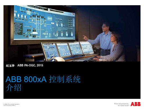
Max 12 Communication modules on CEX bus
Max 12 S800 modules on electrical Modulebus
Up to 45.000 I/O channels per 800xA system
Control Network (Ethernet TCP/IP) Remote S800 I/O via PROFIBUS DP/V1
Max 12 S800 modules per I/O cluster
Max 24 S800 modules per remote I/O station
Optionally redundant S800 modules (max 6 pairs per I/O cluster)
Max 12 S800 modules per I/O cluster Optionally max 6 pairs of redundant S800 modules on base cluster.
Optimization and I/O
- Boiler Protection - Burner Management
Areas
Device Management
Local Panels Control
纪玉学
ABB PA-OGC, 2015
ABB 800xA 控制系统 介绍
© ABB / PA / Control Systems June 30, 2015 | Slide 1
扩展自动化系统 800xA
MES and Business Systems Knowledge Portals as Thin Clients Remote Operator and Engineering Clients
ABB SYSTEM 800xA T530中文课程 07 - FBD Language
直接打开连接对话框
EN 复选框选择该功能块的使能参数有效
FBD 语言
EN 使能参数
EN 使能参数相当于ST语言中的IF语句。 EN 必须连接到一个布尔变量。 如果有EN使能参数,则必须连接。 当EN 输入为真时,函数或功能块才执行,否则,输出保持不变。. EN 可以在插入时打开或关闭,或在编辑属性时打开或关闭。
页面参考 右键点击函数或功能块连线的引脚 Go To Source Go to Sink
© ABB Automation Technology Products AB Page 21 Jan. 2003,
© ABB Automation TechnologyProducts AB. January 2003, Page 22 Control IT AC 800M/C SB2 Translate and Edit by Peng Cao,ATCE/CN
Search For:要搜索的文本。 Search In: 搜索的范围,缺省范围为开始搜 索时所在的POU。 Filter Result:搜索的过滤选项。 Rebuild: 重新编译搜索数据库。
© ABB Automation Technology Products AB Page 20 Jan. 2003,
© ABB Automation Technology Products AB Page 13 Jan. 2003,
必须确保这二个参数一个是输入参数,一个是输出参数。
FBD 语言
注释
函数和功能块注释 鼠标右键点击要编辑注释的函数或 功能块,选择Edit Comment… 命 令,在注释对话框中编辑注释。
获得POU程序的总貌。 选择,拷贝和粘贴函数和 功能块。 创建,修改和删除函数和 功能块。 编辑功能块实例名,编辑 元素。 修改分页和页注释. 查看分页和重编页码。 查看页脚文本。 程序导航。 修改FBD程序代码区中程 序的执行顺序。
ABB_ 800xA组态一个报警和事件的模版
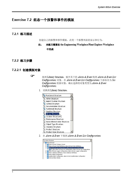
System 800xA Exercise 1Exercise 7.2组态一个报警和事件的模版7.2.1练习描述创建自己的报警和事件模版。
改变一个报警列表的显示和行为。
注:本练习需要在the Engineering Workplace/Plant Explore Workplace中完成7.2.2练习步骤7.2.2.1创建模版对象找到Library Structure ,展开其下的Alarm &Event 找到Alarm &Event ListConfigurations 对象。
在Alarm &Event List Configurations 下添加名为Sxx Configurations 的新对象,确认选择的对象类型为Alarm &Event Configurations .1.切换到Library Structure;2.在Alarm &Event 下找到Alarm &Event ListConfigurations2 3.创建一个类型为Alarm &Event List Configurations 的新对象,命名为Sxx_Configurations☞拷贝位于Common Alarm &Event Configurations 组中的Common Alarm ListConfiguration 对象。
1.选择Common Alarm List Configuration对象并拷贝它☞将其作为一个子对象粘贴到Sxx Configurations 组下。
1.选择Sxx_Configurations 对象并粘贴。
ABB-800XA 系统项目架构
ST
使用ST语言的优点
1. 自由布局程序代码和注释 2. 在在线模式下,可以切换到功能块图或梯形图视图显示 3. 可以使用任何文本编辑器来编写ST代码(如MS Word) 4. ST语言易写易读,是最高效率的代码编写方式 5. SFC程序的代码只能使用ST语言,所以,如果您需要使用SFC程序, 就必须学习ST语言。
Handles one Control project
Builds Control projects
Download to AC 800M controller
800xA System
AC800M Aspect System
Plant Explorer / Engineering Workplace
信号取反:
右键点击函数或功能块参数引脚,选择Invert 命令或 定到这个参数的信号取反。
工具栏按钮,可以将指
信号取反
FBD
FBD编程练习
练习3.3:编写液位监控程序
练习3.4:编写进料阀V1和V4控制程序
目录
n 项目构架 n 变量与数据类型 n 功能块图(FBD)程序 n 结构化文本(ST)程序 n 任务 n MMS通信
ST
ST基本语言元素
条件语句
运算符
If..then.. end_if;
If..then.. else.. end_if;
If..then.. elsif.. else.. end_if;
case <integer> of <integer literal> : <statements>
end_case;
ST
循环语句
运算符 For While Repeat Exit
800XA 系统概述(培训)
Distributed Control Systems have been deployed extensively around the world in process and manufacturing industries to achieve productivity improvements by reducing process variability, increasing production availability, and automating tasks. These improvements were gained by focusing primarily on process control. In the 1990’s ABB led the evolution of control system technology by introducing Open Control Systems. OCSs aimed to “open up” the control system environment, making information from the plant floor available to other applications, and allowing OCS systems to interface with other applications principally related to keeping the process running smoothly. It also marked the first major incorporations of “off-the-shelf” technology to replace proprietary versions of Operator Stations, Engineering Stations, and the like.However, the focus was still primarily on the controlling the process. Today, to deliver additional productivity gains it is necessary to extend the reach of the automation system beyond the world of process control. As mentioned above the traditional DCS / OCS functionality has been the Operations, Engineering, and logic to achieve consistent and predictable Process Control. The Operations functions were focused on the needs of the production operator. Interfaces to applications and devices external to the control system with their own data storage typically were collected and duplicated in the control system database to provide accessibility for reporting and operations needs. This approach was found to be difficult to engineer and maintain. The practice of having information stored in multiple locations brought uncertainty of data integrity as the individual software applications were advanced at asynchronous paces and theWith the introduction of System 800xA, ABB, redefines the standard for control system functionality by extending the reach of the automation system. From an information access and integration perspective the IndustrialIT system incorporates functionality far beyond process control. Specifically, the system incorporates Process Control, Production Management, Safety, Discrete Logic and Sequence Control, Advanced Control, Information Management, Smart Instrumentation, Smart Drives and MCCs, Asset Management, and Document Management capabilities in a singular virtual database environment. The Aspect Object technology inherent to IndustrialIT provides the unifying platform base allowing each application to maintain data in its source application, while providing association to a production asset. This allows access to the data directly from it source in the context of the production asset without the need to know where the data is coming from, and without concern about data integrity and concordance. The ability to extend control engineering standards to incorporate and maintain connections to the wealth of IndustrialIT applications we have discussed, and to deploy these standards efficiently across all like instances is one of the unique characteristics of ABB’s solution.This elegant solution addresses the engineering and maintenance issues of past solutions.This new IndustrialIT Extended Automation System 800xA provides for a single operations, engineering, and information management environmentMeet the Aspect Integrator Platform, a revolutionary open architecture for managing, optimizing every link in the enterprise value chain. This powerful Microsoft Window-based architecture sets the standard for every IIT product from ABB and its partners. The Aspect Integrator Platform is a software package that integrates all Industrial IT enabled products via their Aspect Objects, irrespective of where they may reside.In the grand scheme of IndustrialIT, the information required to support each plant component and each business process is defined as an Aspect Object. An Aspect Object contains all the characteristics – or Aspects – of the item in question. For an electric motor, this could include design drawings, control diagrams, maintenance information, location, quality information and performance trends, even a live video of it in action. But an Aspect Object can also be finished products, raw materials, sales and orders. The key to Aspect Object technology is, however, that it is much more than real-time information. It also defines a set of software functionsb so that everyone in your world can find, use and communicate this information via standard PCs running ordinary applications like Microsoft Word and Excel. The portfolio of product suites that take advantageof Aspect Object functionality is growing all the time. Integrating these products via their Aspect Objects is the task of the Aspect Integrator Platform (AIP). The AIP is thus one of the key elements in the entire IndustrialIT architecture.A particular user configuration is created by dynamically linking a set of Aspect Objects as software components in drag-and-drop fashion.•…Extended Automation System 800xA.•800xa consists today of a mature and comlete producy portfolio intended for all type of industrial automation.•It includes;•Advanced and the latest operator and engineering workplaces •Powerful and flexible controllers and I/O•support for all major standard Fieldbuses on the market•and also products like; (click)•Information management•Asset optimization•Batch management•Safety products. ABB is actually the only supplier, who can compine application for Process Automation AND Safety in the same controller.The solution is Aspect Objects!We do not create one single data model, or object model, to represent the real world object in our systemInstead we model one aspect at a timeThus, the model object is not an object in a strict sense, but rather a container of references to different objects that implement the aspectsThe aspects are implemented by different software systems each of which stores, manages and presents its information in its own optimal wayThese software systems are referred to as aspect systems.The result is a system of integrated but independent software systems ...The solution is Aspect Objects!We do not create one single data model, or object model, to represent the real world object in our systemInstead we model one aspect at a timeThus, the model object is not an object in a strict sense, but rather a container of references to different objects that implement the aspectsThe aspects are implemented by different software systems each of which stores, manages and presents its information in its own optimal wayThese software systems are referred to as aspect systems.The result is a system of integrated but independent software systems ...管理方式A very natural way to represent relations between different entities is to organize them in a structure.Depending on from which perspective we look at it, the same entity fits naturally in several different structures.For example, a certain piece of process equipment has a certain position in a functional structure depending on the functional breakdown of the plant. It is also physically placed somewhere, and thus it has a place in a location structure. The same piece of equipment may currently be allocated to a certain production batch, so it belongs in the batch structure. Because it is used to produce a certain product, it fits in a product structure. And so on.Server software can, from an architectural perspective, run on any (server) node (physical PC) in the system. Multiple server software types can be hosted on a single PC. Server software classifications include:■Aspect: Run the intelligence in the system, including theaspect directory and other services related to objectmanagement, names, security, etc.Connectivity: Provide access to controllers and other data sources. Several groups of connectivity servers may exist in a system, each serving one set of data sources. Examples of services that run ona connectivity server are OPC related services (DA, AE,and HDA), and SysMsg.Application: Run various types of system applications, for example Batch Management, Asset Optimization, Simulationand Optimization, and Information Management.23The growing deployment of peripheral applications related to productivity improvement vastly increases the amount of data available to improve productivity in the plant, utility, or mill. Yet, without the proper context, plant personnel can be exposed to information overload.The 800xA system gathers information from multiple plant sources and transforms it into relevant information for a diverse set of users such as maintenance technicians, process engineers, production managers, or plant operators. The 800xA architecture provides:■ Operators: An environment to allow them to run the plant in a safe way and produce products in required quantity and quality.■ Operations Managers: An environment to let them know what is the return on investment, risk, uptime, and production and maintenance costs at any given time.■ Engineers: An environment that will allow them toimplement specification changes into their running plant in the shortest time with lowest cost at the lowest risk.■ Maintenance and Service Personnel: Information to ensure maximum availability of plants and applications.S500 is a low-end I/O within ABB and will be introduced in Control IT. Planning on-going.•AC 800M HI controller provides ability to combine safety critical loops with control applications to facilitate maximum utilization of process equipment within defined safety boundaries during changingproduction modes.32Avoiding erosion of information and enabling reuse of knowledge can help improve the performance of all plants by promoting more intelligent design and application enhancement800xA provides a Single source of truth for all engineering and plant information that enables the intelligent design process and promotes Operational excellence through the reuse best practices.From the Engineering Workplace, users have access to all system information required to install, configure, operate, and maintain the system. This includes the ability to configure and diagnose Hart, Profibus , and FF devices, as well as remote I/O systems.The System-wide single point of data entry ensures data consistency, eliminates duplication of effort, and guarantees the information is accurate and up to date. Plant and device documentation can also be directly accessed from within the engineering environment.System 800xA provides a flexible, distributed engineering environment through the use of application servers. These servers manage project data and make it accessible to on-site connected users or isolated off-site engineering environments.In a multi-user on-site environment, a variety of engineering tasks may be performed on a target system simultaneously. The results are applied to the target system automaticallyvia the application servers.In an off-site environment, engineering tasks may be performed off-line in an isolated manner from other users. When the off-site tasks are completed, the user modifications can be applied to the on-line system through the application server’s import/export features.The import/export feature allows for selective transfer of configuration data between systems. In addition, it is possible to compare configuration data between the different systems and create reports on the differences.Process Portal faceplates have a standardized look and feel throughout. No matter which control system is being used, the operator always has a consistent presentation of the object. The operator will know exactly how to proceed in all situations.Faceplates have three different appearances. The minimal view where the most important information occupies as little space as possible. The normal view shows more links and graphics. The extended view provides full access to tuning and adjustable parameters. The standard set of faceplates can be used as is or modified. It is very easy to customize the faceplates. This standardized faceplate frameworkreduces configuration time to a minimum.A scenario showing how you can use the alarm management in a scenario. The scenario starts with that you get a alarm via sound. You go to your station and ou see that the alarm is in area AR14, you click on the alarm band to get to the complete alarm list of the area. If you are not satisfied with what you see, you can easily sort/filter the list. You do not know what to do to you click on the premade instructions for this alarm. You realize what you want to do and clicks on the alarm line to bring up the faceplate. You acknowledge the alarm and tune your loop and navigate directly to the process graphics for the area. Before you end you enter what you have done in the Alarm Comment.Each CFA within 800xA, including Batch Management, has integrated features from the core system platform. This makes validation of the entire system as simple as possible. Core platform features include:•Security / Access Control•Authentication•Versioning and Synchronization•Electronic-Signatures•Signature to Record linking•Audit Trail•Native Language supportAdditionally, Batch Management continues to provide recipe life-cycle management with support for versioning of recipe procedures. Batch Management also provides a difference report view so that the user canreadily compare two versions of a recipe.52。
ABB DCS 系统 培训课程 系列讲座 Course Information
Chapter 1 Course Information1.1 NameCourse: T530Control Builder Professional, Configuration1.2 Duration5 days.1.3 DescriptionControl Builder Professional is a programming tool on MS-Windows 2000 for threedifferent Control Products, AC 800M, AC 800C, SoftControl and AC 250.Control Builder Professional is implemented according to the standard ofIEC 61131-3, which is an international standard for PLC-programming. ControlBuilder Professional can be programmed in five languages by using Function Blocks,Control Modules and declaration of variables. A variable consists of a name and aData Type, and does not have a specific address in the system. Data can be exchangedwith other systems using MMS, SattBus and COMLI communication.The course goal is to teach students the conceptions, functions and structure in ControlBuilder Professional and how to navigate in the system.Topics included:∙The integrated system – An introduction∙IEC 61131-3∙ABB Extensions and simplifications of IEC 61131-3∙Getting Started∙Variables and data types∙ST Language∙IL Language∙FBD Language∙LD Language∙SFC Language∙Using Functions and Function Blocks∙Creating Function BlocksChapter 1 Course Information∙Hardware Configuration∙Connecting variables to I/O∙Tasks in the templates∙Downloading /Online∙Using Control Modules∙Creating Control Modules in the application and in libraries∙Creating interaction windows associated to function blocks or modules?∙Code sorting∙Some Function Blocks and Control Modules in Standard libraries∙Communication∙Projects with several applications / controllers∙Analyze∙Privilege handling∙Hidden/Protected code∙Licensing∙Backup/Restore1.4 ObjectivesThe course goal is to teach students the conceptions, functions and structure in ControlBuilder Professional and how to navigate in the system.Upon completion of this course the participant will be able to:∙Configure the systems AC 800M/C, SoftControl and AC250 using ControlBuilder Professional.1.5 Student ProfileSystem, process, and application engineers. Instrumentation, electrical, and serviceengineers.The course is meant for programmers that should write programs for AC 800M/C,SoftControl or AC 250.1.6 Prerequisites∙Basic knowledge of how controllers are configured / programmed∙Basic knowledge of how processes are controlled∙Basic knowledge of Windows NT / Windows 20001.7 ExercisesIn this section you will find information how the exercises are built up during thecourse in order to get a “flow” in the learning.The idea is to build up a complete control of a course process model.However, when doing the basic exercises for the languages FBD and ST, it is moresuitable to do them without involving the model.When Function Blocks are introduced, one exercise will be to build the process model.The process model can then be tested in simulate mode.After this, the sequence language SFC is introduced. This means that an exercise willbe to make a sequence, involving inlet and outlet valves filling/emptying a tank, that isa part of the model. That sequence will be tested in simulate mode.Later in the course I/O connection is treated, which means that the variables from theprevious exercises can be connected to I/O.The same sequence structure is used with the Control Modules later in the courseFinally, a backup of the project is made.Chapter 1 Course Information1.8 Course CalendarSyllabus1.9 Reference Material1.9.1 IntroductionThe student gets this course binder. Control Builder Professional has built in manualsin the help menu.Each classroom has reference documentation sets available to provide you withadditional information if necessary.To order the product documentation NOT found in your course binder, contact yourlocal sales office or ABB headquarters.1.9.2 Product ManualsProduct Manuals are product- documents developed by the documentation departmentwithin ABB Automation Products. They are all included on the Control Builderinstallation CD. The manuals are a part of the built in help.1.9.2.1 Control Builder Manuals1.9.2.2 Control Builder Related Manuals - SoftwareChapter 1 Course Information1.9.2.3 Control Builder Related Manuals – Hardware1.10 Legend< > Indicates a key name.> Indicates a menu selection path.| Indicates when you go from one pop-up menu to a sub-pop-up menu.Bold Indicates a pop-up menu name or an option in a pop-up menu.☞Indicates a student activity.☐Question to be answered by the student.Chapter 1 Course InformationThis page is intentionally left blank1.11 Feedback information to ABBPlease evaluate this course binder and use this page to notify us of problems orsuggest improvements.Course binder for: Course T530, Control Builder, ProgrammingProblems are found on the following on page/pages:(If possible attach a copy of page and correction.)Recommended improvements:(Attach additional information if needed.)ABB has the right to use submitted suggestions without obligations, with all ideasbecoming property of ABB.Please send this page to your local ABB Training Center or to:ABB Service ABABB Automation UniversityTraining Center - MalmöSE-205 22 MALMÖSWEDENFax: +46 40 55 03 14Please fill in the data bellow in case we need to contact you (optional).Name:Address:Telephone:e-mail:Chapter 1 Course Information1.12 Course EvaluationCourse T530Date Control Builder Professional, Configuration Training Engineer Location Your Job TitleYour Name[opti onal]We are interested in your honest opinion and ideas to help us improve our courses so you get the satisfaction you deserve. Please complete this form and add additional comments (particularly in areas where improvement is needed). Include explanations for any negative comments. Thank you.E x c e l l e n tV e r y G o o d S a t i s f a c t o r y F a i rP o o rCheck your opinion .1. Quality of training engine er’s presentation2. Adequacy of course contents3. Quality of training documentation4. Adequacy and quality of training equipment5. Was the training engineer adequately prepared to teach thiscourse? 6. Were course and lesson objectives communicated to you? 7. Was the training engineer helpful and receptive to questions ordifficulties? 8. Were the lab exercises effective in helping you learn?9. Was the facilities in and around the lecture room to your satisfaction 10. Was our staff friendly and courteous? 11. Did the course meet your expectations? 12. How do you rate the course overall?13. What topics would you like to see added to the course and why?14. What topics would you like to see deleted from the course and why?Comments and Recommendations:(Use the reverse side or additional paper if necessary)Chapter 1 Course InformationThis page is intentionally left blankChapter 1 Course InformationThis page is intentionally left blankTA BLE OF CONTENTSChapter 1 Course Information (1)1.1 Name (1)1.2 Duration (1)1.3 Description (1)1.4 Objectives (2)1.5 Student Profile (2)1.6 Prerequisites (3)1.7 Exercises (3)1.8 Course Calendar (4)1.9 Reference Material (5)1.9.1 Introduction (5)1.9.2 Product Manuals (5)1.9.2.1 Control Builder Manuals (5)1.9.2.2 Control Builder Related Manuals - Software (5)1.9.2.3 Control Builder Related Manuals – Hardware (6)1.10 Legend (7)1.11 Feedback information to ABB (9)1.12 Course Evaluation (11)Chapter 1 Course InformationThis page is intentionally left blank。
800xA-Training-AC800M常用功能块一
800xA-Training-AC800M常用功能块一AC800M系统常用功能块简要说明(一)第一章主要列出了常用功能块的简要说明,以后同学们可以根据使用手册仿真测试,熟悉每个管脚的作用。
功能块的左侧都是连接输入变量也就是常说的读变量,右侧都是连接输出变量也就是常说的写变量系统功能块:将一些常用的逻辑控制,数据转换,电机控制,阀门控制方案集成为控制块,方便用户直接调用,给用户提供一个功能性的模板,用户可以根据自身需求在此基础上进行二次开发。
自定义功能块:编程人员根据实际需求结合基本块,自己发出需要的功能块,如果该功能块需要操作面板的话,用户也可以自己定义上位机操作面板。
ABB编程方式Diagram,controlModule,Program是基于功能块上使用,将功能块图表化或者语言化脸实现控制。
我们在使用过程中可以结合实际使用不同的编程语言,可以减少工作量,简化工作任务。
本文是一个系列文章主要分为三个章节,后续章节会在百度文库中陆续上线,可以关注本人百度文库,方便后续学习,这里特别说明由于ABB-DCS系统中文资料较少,且有些翻译不是特别准确,这里建议学习的同学们可以学着看看英文手册,本说明中也含有部分英文或者截图请同学们耐心查看。
模件错误代码查询1.IO模块硬件通道状态通道输入变量后缀加“.status”In.Status=16#C为单元错误,In.Status=16#10为通道错误,In.Status=16#56为通道超量程(毫安值过高),In.Status=16#55为通道低量程(毫安值过低)上面列出了常出现的几种通道状态,其它的状态值代表含义可以参考说明手册。
2.硬件单元状态下面列出了硬件单元如控制器、冗余通信模块等运行状态,错误代码,具体错误信息可以参考说明手册。
ABBAC800M中基本库1.And(与)基本功能块“与”一般是BOOL量操作,真值表如下图,无操作面板2.Or(或)基本功能块“或”一般是BOOL量操作,真值表如下图,无操作面板3.Not(非)基本功能块“非”一般是BOOL量操作,功能块前后的值时相反的状态,无操作面板4.ABS(普通绝对值函数)普通的绝对值函数5.AddSUFFix当要在SIL应用程序中添加两个字符串变量时,可以使用addsuffix函数。
ABB变频器-acs800课程中文教程资料
-软件 7.X ->
ABB
Master and Follower
Master / Follower
主从控制: 主从应用程序用于设备 由几台 ACS600或ACS800 传动驱动。电机轴用齿
主从控制
轮,链条和皮带联系。
特性从16ms改善为4ms
© ABB Drives -ACS800 page 10
4个控制地点
• Extruder macro is available for all ACS 800 inverter types.
全部类型都有挤压控制宏。
ABB
Crane
提升机控制
对于提升机应用,标 准的提升机安全特性 和功能特性已经内置 于传动中。软件中含 有标准的接口模块用
于操纵杆控制,脚踏
© ABB Drives -ACS800 page 7
ABB
ACS 800 与ACS 600相兼容
ACS 600/800 产品 可以有哪几种应用程序?
ACS 600/800 SingleDrive 产品家族包括一
系列设备可以灵活地用于广泛的工业应用场合 。下表说明了 ACS 600/800 的应用实例
-带有倾析器 宏的软件
ABB
Extruder
挤出机控制
在挤出机应用中,一般是颗粒状或粉末状的 材料被螺杆钻动,形成可塑的材料以便以后 加工成形
• High starting torque without encoder, excellent speed accuracy without encoder. • Adaptive torque limitation feature: set by digital input, analog input or fieldbus. • Two sets of parametrised stall protection functions to detect material jam. • Secure thermal protection for motor through PT-100 and PTC connection. • Control through fieldbus or I/O. • Emergency stop function through digital input. • Digital potentiometer with two different accelerating and decelerating ramp times. • Possibility to change over between four control locations on-line. • Extruder macro is available for all ACS 800 inverter types. 所需 ACS 600 软件和可选件 -带有倾析器 宏的软件
ABB 800xA系统画面新手教程---动态变化
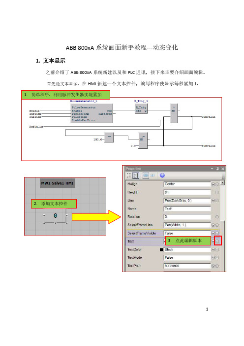
ABB 800xA系统画面新手教程---动态变化1.文本显示之前介绍了ABB 800xA系统新建以及和PLC通讯,接下来主要介绍画面编辑。
首先是文本显示,在HMI新建一个文本控件,编写程序使显示每秒累加1。
2.添加文本控件3.点此编辑脚本12代码中有一些固定函数我们可以使用,如下:4. 点击左边图标,在SM1下找到程序中的SumValue 变量,编写如上代码Substring,截取字符串,上文也用到了此函数因此上文代码:Substring(String($'Application_1/Control Modules/SM1:SumValue'), 0, 4)其含义就是先把SumValue转成字符串,然后从第1个字符开始共截取4个字符。
34最后效果如下:52. 物体动态变化HMI 新建一个圆,让其从左到右循环滚动。
1. 新建控件6这个很容易理解,先找到HMI 上物体最左和最右两个坐标,如下:然后根据线性关系,Xpos 的代码就是:150+6.4*SumValue ,当SumValue 从0~100开始变化时,X 坐标就从640移动到790。
实际效果如下: 这里是150程序中54物体实际位置73. 颜色变化物体在最左,中间以及最右时有颜色显示。
1. 新建3个小方块控件3. 同上文一样,在此处编写代码8代码:if 97. <= $'Application_1/Control Modules/SM1:SumValue' &&$'Application_1/Control Modules/SM1:SumValue' <= 100. Then rsGeneralAlarm else Gray简单的一个If Else 语句,以最右显示为例,当SumValue 值在97~100时显示红色,其它位置则显示灰色。
效果如下:颜色变化除了上数字范围来显示,我们也可以用bool 量,相当于实际碰到限位开关来触发颜色变化。
ABB SYSTEM 800xA T530中文课程 17 - Control Modules
使用图形化的控制模块图编辑器。
修改控制模块。. 在新库中,通过其它控制模块创建新的控制模块。 使用图形可视化编程。
了解面向对象的概念。
连接控制模块中的信号到I/O。 创建功能块和控制模块的简单交换式窗口。
© ABB Automation Technology Products AB Page 3 Jan. 2003,
控制模块编辑器
控制模块编辑器是一个画图和编程的组合工具,可以创建和编辑图形对象 并连接变量到这些对象,从中可直接访问POU编辑器,声明变量和参数。
你既可以在控制模块编辑器中创建新的控制模块,也可以编辑修改已有的 控制模块。其画图功能不仅包括基本形状(线,矩形等),还包括用于交 互式窗口的对象(选项按钮,复选框等)以及复合的对象(棒图,字符串 选择等)。图形对象可以是动态的。
© ABB Automation Technology Products AB Page 21 Jan. 2003,
CM图形
添加图形到控制模块
CMD编辑器中的工具
在CMD编辑器的工具栏中有一些可以使用的工具,下面是一 些常用的重要工具:
© ABB Automation Technology Products AB Page 22 Jan. 2003,
CM图形
添加图形到控制模块
控制模块图形的概念 通过CMD编辑器可以在控制模块中添加图形内容。在下面的情况下 控制模块图形很有用:
在开发阶段,一个交互式窗口使得操作变量和参数的值非常容易。 在调试阶段,在实际条件未具备时,用图形来模拟来自工厂的响应。. 作为过程对象的维护工具,一个图形化的操作面板可以显示联锁状态, 允许手动操作等。 注意:控制模块的图形并不打算替代HMI,而是对HMI的 补充,主要用于测试,维护和导航。
ABB DCS 系统 培训课程 系列讲座 T530 2_Title Page and Disclaimer
Control ITControl BuilderProfessional,Configuration Student Training BinderCourse T5303BSE 022 837/A00-12Course T530Use of DANGER, WARNING, CAUTION, and NOTEThis publication includes, DANGER, WARNING, CAUTION, and NOTE information where appropriate to point out safety related or other important information.DANGER Hazards which could result in severe personal injury or deathWARNING Hazards which could result in personal injuryCAUTION Hazards which could result in equipment or property damageNOTE Alerts user to pertinent facts and conditionsAlthough DANGER and WARNING hazards are related to personal injury, and CAUTION hazards are associated with equipment or property damage, it should be understood that operation of damaged equipment could, under certain operational conditions, result in degraded process performance leading to personal injury or death. Therefore, comply fully with all DANGER, WARNING, and CAUTION notices.TRADEMARKSThe following are registered trademarks or trademarks of Asea Brown Boveri: Advant Station, AdvaCommand, AdvaBuild, AdvaInform, ABB Master, MasterAid, MasterBatch, MasterBus, MasterFieldbus, MasterGate, MasterNet, MasterPiece, MasterView, ABB Stressometer, AccuRay, AccuRay 1190, 7000 MICRO, 1180 MICRO, MICROSET, FLEX, MICROLINK, FirstSight, Profile Manager, DeltaComm, MICRO-Ten, Batch 300, and ABB MOD 300.Motif and OSF are registered trademarks of Open Software Foundation. UNIX is a registered trademark of UNIX System Laboratories, Inc. X Window System is a trademark of Massachusetts Institute of Technology. AutoCAD is a registered trademark of AutoDesk, Inc. DEC, VAX and VMS are trademarks of Digital Equipment Corporation. FrameMaker is a trademark of Frame Technology Corporation. ORACLE, SQL*Menu, SQL*Forms, SQL*Plus, SQL*ReportWriter, andSQL*Net are trademarks of the Oracle Corporation. DESQview is a trademark of Quarterdeck Software. MS–DOS is a trademark of Microsoft Corporation. IBM is a trademark of International Business Machines Corporation.NOTICEThese documents have been assembled and produced for educational purposes. The contents of your course binder will not be updated to include future amendments.We appreciate, however, your comments on our course documents. These will help us make improvements for future courses, based on practical experience.The information in this document is subject to change without notice and should not be construed as a commitment by ABB. ABB assumes no responsibility for any errors that may appear in this document.In no event shall ABB be liable for direct, indirect, special, incidental or consequential damages of any nature or kind arising from the use of this document, nor shall ABB be liable for incidental or consequential damages arising from use of any software or hardware described in this document.This document and parts thereof must not be reproduced or copied without ABB’s written permission, and the contents thereof must not be imparted to a third party nor be used for any unauthorized purpose.You should yourself study those parts of the material, if any, which are not covered during the course.As a user of our training equipment, you must read carefully the safety instructions.Participation in a course means more than passive receiving of information. It also requires activity on your part and our courses therefore contain frequent practical exercises. Make use of these opportunities to test and acquire familiarity with the equipment and aids used.With best wishes for a rewarding course.Copyright © ABB Service AB 19993BSE 022 837/A。
800xA-系统安装简易指南
800xA-系统安装简易指南800xA 系统安装简易指南Project: 新疆广汇Title: 800xA 系统安装简易指南Prepare: feng yong ABB China Ltd. PA/PIPS; Check :jiangqi ABB China Ltd. PA/PIPS; Final Check: ABB China Ltd. PA/PIPS;Modifications listRev. ind. Page (P)Chapt. (C)Description Date Dept./Init.Initial Version 文本的第一版2009/9/3Jiangqi/fengyongPA/PIPS11 概述该文档为描述800Xa V5.0 SP2 REVB版本的安装简易指南,包括操作系统设置,安装步骤,已经安装结束后的XA系统的设置以及安装过程中应该注意的事项。
安装可以使用手动和自动两种方式。
初次安装为提高效率,可以采用自动安装完成;如果安装结束后还需要添加软件项,使用手动进行有选择的安装。
系统自动安装的基本流程为:安装前系统准备、系统设计计划、系统安装2 安装前系统准备2.1 操作系统软件和硬件准备⏹计算机硬件要求严格根据ABB800XA系统认证第3方设备文件的要求来配置高品质的服务器和工作站产品通常系统中服务器内存至少需要4G;工作站内存至少需要2GC:盘的大小:因为800xA系统中历史记录,报警记录等信息的存储默认盘为计算机操作系统的C盘。
因此有必要对C盘留够足够大的空间。
建议为20G。
⏹操作系统软件:(一定需要正版软件)Windows Server 2003 R1 with SP2 or R2 with SP2or Windows XP Professional with SP2 or SP3.服务器上通常安装windows 2003 server R2 SP2工作站可以安装windows XP SP3The 800xA 系统要求工作在NTFS 文件系统所有服务器和工作站上都建立以下用户名(有administrator 权限)用户名800xAInstaller 密码********⏹第三方软件Office 2007 SP1或者Office 2003 SP3如果Graphic Builder 未来基于VB,还需要VB6+sp6⏹ABB 软件800xA System DVD V5.0 SP2 REVB系统授权文件2.2 操作系统设置• Virtual Memory Configuration对于客户端,虚拟内存大于1.5GB.对于服务器,虚拟内存应该是2.5倍的物理内存,或者至少1.GB。
ABB 800xA System AC800M培训教材
© ABB - Page 1
Industrial IT System 800xA
Chapter 1 Overview
Extended Automation System 800xA
© ABB - Page 2
© ABB - Page 3
System Architecture
800xA System 总览
配置向导 是800xA核心管理位置用于: 创建/删除 800xA系统 启动/停止 800xA系统 添加扩展到800xA系统 连接/断开 客户端和服务器
© ABB - Page 22
© ABB - Page 23
System Architecture
Client之新增與移除
Industrial IT System 800xA
Simulation Model
Operator Notes
© ABB - Page 10
System Architecture
直观化的存取
通过滑动鼠标右键即可快速轻易地存取全部的资讯。 可以非常方便的操作。
Right click on the object in the Graphic
Right click on the object in the Alarm List
Aspect Framework / System 800xA Platform
Aspect Framework (Afw)
AC800M
Advant
Harmony Melody
Other OPC
Connectivity componeBB - Page 14
System Architecture
800xA(Extended Automatic)产品总览
- 1、下载文档前请自行甄别文档内容的完整性,平台不提供额外的编辑、内容补充、找答案等附加服务。
- 2、"仅部分预览"的文档,不可在线预览部分如存在完整性等问题,可反馈申请退款(可完整预览的文档不适用该条件!)。
- 3、如文档侵犯您的权益,请联系客服反馈,我们会尽快为您处理(人工客服工作时间:9:00-18:30)。
开始新项目
软件安装
开始新项目
语言设置
© ABB Automation Technology Products AB Page 5 Jan. 2003,
通过Setup Wizard设置系统菜单的语言: Start > Programs >ABB Industrial IT AC800M> Utilities > > Setup Wizard 启动设置向导:
© ABB Automation Technology Products AB Page 11 Jan. 2003,
© ABB Automation Technology Products AB Page 12 Jan. 2003,
POU 编辑器
信息区
代码区
声明区
工具栏
POU 编辑器
POU 编辑器
打开项目
File > Open Project… 或
开始新项目
项目管理器
菜单 工具栏按钮
工具栏按钮
菜单项
File > New Project… File > Open Project Tools > Test Mode
热键
Ctrl + N
说明
创建一个新项目。
项目树窗口
Ctrl + O
打开一个已有的项目
插入代码块 删除代码块 改变编程语言 代码块重命名
© ABB Automation Technology Products AB Page 15 Jan. 2003,
排列代码块
选择代码块
© ABB Automation Technology Products AB Page 16 Jan. 2003,
POU 编辑器
声明区
声明区可以声明变量、参 数、功能块和数据类型元 素。不同的编辑器,可以 在变量声明区底部的选择 标签上选择显示不同的声 明表格。 变量 程序中的数据是以变量形式 保存的,每个变量必须声明 一个变量名和数据类型。一 个程序可以包含多个变量。 程序中的变量必须在声明后 才能使用。 功能块 在使用ST语言或IL语句编程时,必 须先在声明区的功能块标签页声明 功能块,然后才可以使用这个功能 块。(在FBD和LD编程时不用事先 声明就可以直接使用)。
© ABB Automation Technology Products AB Page 8 Jan. 2003,
开始新项目
项目树
开始新项目
下部窗口
Description 标签页 在项目树中选择一个 对象,则在该对象的 编辑器中输入的说明 信息将会显示在窗体 中。
Check 标签页 当鼠标右键点击一个应 用或应用中的程序选择 Check时,Check的结果 信息将显示在此,如果 check结果中出现错误信 息,双击错误信息,将 打开相应的编辑器并定 位到错误所在的位置。
© ABB Automation Technology Products AB Page 14 Jan. 2003,
POU 编辑器
POU 编辑器
代码区 代码区可以分成多个代码块, 不同代码块中的程序可以用不 同的语言编写。 功能块和程序的执行顺序是 由代码块的从左到右的排列 顺序决定的,上图中,代码 执行的顺序为CodeBlock1, CodeBlock2 和 CodeBlock3 ,该顺序可以通过菜单Edit > CodeBlock命令或鼠标右 键点击代码块标签修改。
Tools > Online
© ABB Automation Technology Products AB Page 7 Jan. 2003,
Tools > Stop Test Mode Tools > Downloa d Project and Go Online Help Topics
下部窗口
进入在线帮助。
Chapter 5 入门
General
入门
目标
完成本章的学习,将能够:
© ABB Automation Technology Products AB Page 2 Jan. 2003,
掌握软件的安装. 熟悉项目资源管理器. 创建一个新项目. 基本掌握POU编辑器的使用. 检查,应用和保存程序 仿真和测试项目.
Message 标签页 Message 标签页在下部窗体 显示系统活动的信息,如 从离线模式切换到在线模 式或打开文件等。
© ABB Automation Technology Products AB Page 9 Jan. 2003,
© ABB Automation Technology Products AB Page 10 Jan. 2003,
General
内容
POU编辑器
开始一个项目
仿真和在线帮助
POU 编辑器
POU
IEC 61131标准将程序,功能块和函数都描述为程序组织单元-POU ,POU有助于将自动化项目组织为代码块,以便减少代码输入,优化 代码结构和便于代码维护。功能块和函数POU在一个递归结构中多次 使用。除了这2种POU,还有程序POU,程序POU是唯一一个不能在 其它的POU中重复使用的。
General
内容
POU编辑器
开始一个项目
仿真和在线帮助仿真和帮助仿真和Fra bibliotek助仿真
没有任何实际的硬件,我们也可 以在PC机上对项目进行仿真测试 。保存项目并使用工具栏按钮 或选择菜单 Tools> Test Mode 来 对项目进行仿真测试。
在线帮助 使用按钮 或Help >Help Topics 打开帮助主题,如果 选择Help >Manual 菜单,将 打开Compact Control Builder AC800M的使用手册。
Check标签页 程序进行Check检查时, Check的结果信息将显示 于此,如果Check结果中 出现错误信息,双击错 误信息,将打开相应的 编辑器并定位到错误所 在的位置。
Find in Editor标签页 当使用Find in Editor命令 查找时,查找的结果将 显示在信息显示区。双 击结果,快速定位到程 序中的相应位置。
© ABB Automation Technology Products AB Page 13 Jan. 2003,
POU 编辑器
POU 编辑器
信息显示区 信息显示区由三个标签页组成:Description, Check 和 Find in editor.
Description标签页 在description标签页中 ,输入有关程序的说 明文本,可以在项目 资源管理器中的信息 显示区Description标 签页中显示。
© ABB Automation TechnologyProducts AB. January 2003, Page 1 Control IT AC 800M/C SB2 Translate and Edit by Peng Cao,ATCE/CN
Compact Control Builder AC 800M组态培训 Course T530
开始新项目
启动Compact Control Builder AC800M
启动程序 Start > Programs > ABB Industrial IT AC800M > Compact Control Builder AC800M
新建项目 File > New Project… 或
© ABB Automation Technology Products AB Page 6 Jan. 2003,
使用在线帮助.
© ABB Automation Technology Products AB Page 3 Jan. 2003,
General
内容
POU编辑器
开始一个项目
仿真和在线帮助
© ABB Automation Technology Products AB Page 4 Jan. 2003,
© ABB Automation Technology Products AB Page 17 Jan. 2003,
© ABB Automation Technology Products AB Page 18 Jan. 2003,
使用该工具栏按钮在没 有控制器的情况下,对 用户程序进行离线仿真 测试。所有任务经过编 译和仿真,并在PC机上 执行。 F5 使用该工具栏按钮连接 到控制器,即在运行模 式下调试程序代码。 在在线调试模式或仿真 测试模式下返回离线模 式。 Ctrl + D 编译应用中的程序代码 并下装到控制器中执行 。项目资源管理器自动 进入到在线调试模式。
