M8831替换BP2831资料
ME8311--M5835
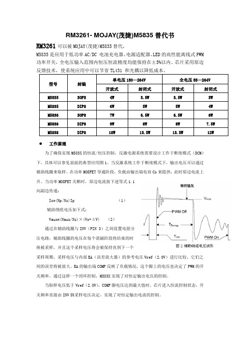
RM3261- MOJAY(茂捷)M5835替代书工作原理为了确保实现M583X的恒流/恒压控制,反激电源系统需要设计工作于断续模式(DCM)下,具体可以参见前面的典型应用图1。
当反激系统工作于断续模式下,输出电压可以通过辅助线圈来取样。
在功率MOSFET导通阶段,负载由输出端电容Co来提供,此时原边电流上升。
当功率MOSFET关断时,原边电流按下述等式1.1向副边传递:Is=(Np/Ns)Ip (1)辅助绕组电压如下式:Vaux=(Naux/Ns)×(Vo+ΔV) (2)通过在辅助线圈与INV(PIN 3)之间设置电阻分压电路,辅助线圈的电压在每个消磁阶段将结束的时候被采样,并且这个采样电压将会被保持直到下一个采样周期。
采样电压与内部EA(误差放大器)的参考电压Vref(2.0V)进行比较,它们之间的误差将被放大。
EA的输出端COMP反映了负载情况,这个脚上的电压也决定了PWM的开关频率,通过这样一个闭环控制,M583X实现了对恒定输出电压的控制。
当取样电压低于Vref(2.0V),COMP脚电压达到最大值时,芯片进入恒流控制状态,开关频率直接由INV脚采样电压决定,实现了对恒定输出电流的控制。
●恒流和输出功率的调节在M583X里,恒流点和最大输出功率可由CS端的采样电阻RS来调节,见典型应用图,输出功率可以通过CC点变化来调节,RS大,输出功率小,RS小,输出功率大,说明见图3 。
●工作开关频率M583X的开关频率是根据负载的条件和工作模式控制的,无需外部元件设定频率,最大输出功率时,开关频率为60KHz,在DCM方式反激工作情况下,最大输出功率可由下式给出:Po max=(1/2)LpFsw Lp²(3)这里Lp为初级线圈电感,Ip为初级峰值电流,参考式(3),初级电感量的变化将导致最大输出功率的变化和恒流模式下输出电流的变化,为补偿初级电感偏差的变化,开关频率将有内部环路锁定,如下式:Fsw=1/(2Tdemag) (4)由于Tdemag和电感成反比,可使Ip和fsw乘积为恒定。
LM2831YMFX资料

LM2831High Frequency 1.5A Load -Step-Down DC-DC RegulatorGeneral DescriptionThe LM2831regulator is a monolithic,high frequency,PWM step-down DC/DC converter in a 5pin SOT23and a 6Pin LLP package.It provides all the active functions to provide local DC/DC conversion with fast transient response and accurate regulation in the smallest possible PCB area.With a minimum of external components,the LM2831is easy to use.The ability to drive 1.5A loads with an internal 130m ΩPMOS switch using state-of-the-art 0.5µm BiCMOS technol-ogy results in the best power density available.The world-class control circuitry allows on-times as low as 30ns,thus supporting exceptionally high frequency conversion over the entire 3V to 5.5V input operating range down to the minimum output voltage of 0.6V.Switching frequency is internally set to 550kHz, 1.6MHz,or 3.0MHz,allowing the use of extremely small surface mount inductors and chip capaci-tors.Even though the operating frequency is high,efficien-cies up to 93%are easy to achieve.External shutdown is included,featuring an ultra-low stand-by current of 30nA.The LM2831utilizes current-mode control and internal com-pensation to provide high-performance regulation over a wide range of operating conditions.Additional features in-clude internal soft-start circuitry to reduce inrush current,pulse-by-pulse current limit,thermal shutdown,and output over-voltage protection.Featuresn Space Saving SOT23-5Package n Input voltage range of 3.0V to 5.5V n Output voltage range of 0.6V to 4.5V n 1.5A output currentnHigh Switching Frequencies 1.6MHz (LM2831X)0.55MHz (LM2831Y)3.0MHz (LM2831Z)n 130m ΩPMOS switchn 0.6V,2%Internal Voltage Reference n Internal soft-startn Current mode,PWM operation n Thermal ShutdownnOver voltage protectionApplicationsn Local 5V to Vcore Step-Down Converters n Core Power in HDDs n Set-Top Boxesn USB Powered Devices nDSL ModemsTypical Application Circuit2017486420174881August 2006LM2831High Frequency 1.5A Load -Step-Down DC-DC Regulator©2006National Semiconductor Corporation Connection Diagrams201748016-Pin LLP201748035-Pin SOT-23Ordering InformationOrder Number Frequency OptionPackage Type NSC Package DrawingTop Mark Supplied As LM2831XMF 1.6MHzSOT23-5MF05A SKYB 1000units Tape and Reel LM2831XMFX 3000units Tape and Reel LM2831XSD LLP-6SDE06A L193B 1000units Tape and Reel LM2831XSDX 4500units Tape and Reel LM2831YMF 0.55MHzSOT23-5MF05A SKZB 1000units Tape and Reel LM2831YMFX 3000units Tape and Reel LM2831YSD LLP-6SDE06A L194B 1000units Tape and Reel LM2831YSDX 4500units Tape and Reel LM2831ZMF 3MHzSOT23-5MF05A SLAB 1000units Tape and Reel LM2831ZMFX 3000units Tape and Reel LM2831ZSD LLP-6SDE06AL195B1000units Tape and Reel LM2831ZSDX4500units Tape and ReelNOPB versions available as wellL M 2831 2LM2831 Pin Descriptions5-Pin SOT23Pin Name Function1SW Output switch.Connect to the inductor and catch diode.2GND Signal and power ground pin.Place the bottom resistor of the feedback network as close aspossible to this pin.3FB Feedback pin.Connect to external resistor divider to set output voltage.4EN Enable control input.Logic high enables operation.Do not allow this pin to float or begreater than VIN+0.3V.5VIN Input supply voltage.Pin Descriptions6-Pin LLPPin Name Function1FB Feedback pin.Connect to external resistor divider to set output voltage.2GND Signal and power ground pin.Place the bottom resistor of the feedback network asclose as possible to this pin.3SW Output switch.Connect to the inductor and catch diode.4VIND Power Input supply.5VINA Control circuitry supply voltage.Connect VINA to VIND on PC board.6EN Enable control input.Logic high enables operation.Do not allow this pin to float or begreater than VINA+0.3V.DAP Die Attach Pad Connect to system ground for low thermal impedance,but it cannot be used as aprimary GND connection.3Absolute Maximum Ratings (Note 1)If Military/Aerospace specified devices are required,please contact the National Semiconductor Sales Office/Distributors for availability and specifications.VIN -0.5V to 7V FB Voltage -0.5V to 3V EN Voltage -0.5V to 7V SW Voltage -0.5V to 7VESD Susceptibility2kV Junction Temperature (Note 2)150˚CStorage Temperature −65˚C to +150˚CSoldering InformationInfrared or Convection Reflow (15sec)220˚COperating RatingsVIN3V to 5.5V Junction Temperature−40˚C to +125˚CElectrical CharacteristicsVIN =5V unless otherwise indicated under the Conditions column.Limits instandard type are for T J =25˚C only;limits in boldface type apply over the junction temperature (T J )range of -40˚C to+125˚C.Minimum and Maximum limits are guaranteed through test,design,or statistical correlation.Typical values represent the most likely parametric norm at T J =25˚C,and are provided for reference purposes only.Symbol ParameterConditionsMin Typ Max Units V FB Feedback VoltageLLP-6and SOT23-5Package 0.5880.6000.612V ∆V FB /V INFeedback Voltage Line Regulation V IN =3V to 5V0.02%/V I B Feedback Input Bias Current 0.1100nA UVLOUndervoltage Lockout V IN Rising 2.73 2.90VV IN Falling1.852.3UVLO Hysteresis0.43VF SWSwitching FrequencyLM2831-X1.2 1.6 1.95MHz LM2831-Y 0.40.550.7LM2831-Z2.253.0 3.75D MAXMaximum Duty CycleLM2831-X8694%LM2831-Y 9096LM2831-Z 8290D MINMinimum Duty CycleLM2831-X5%LM2831-Y 2LM2831-Z7R DS(ON)Switch On Resistance LLP-6Package 150m ΩSOT23-5Package 130195I CL Switch Current Limit V IN =3.3V1.82.5A V EN_TH Shutdown Threshold Voltage 0.4V Enable Threshold Voltage 1.8I SW Switch Leakage 100nA I ENEnable Pin CurrentSink/Source100nA I QQuiescent Current (switching)LM2831X V FB =0.553.35mA LM2831Y V FB =0.55 2.84.5LM2831Z V FB =0.55 4.3 6.5Quiescent Current (shutdown)All Options V EN =0V30nAL M 2831 4Electrical Characteristics VIN=5V unless otherwise indicated under the Conditions column.Limits in standard type are for T J=25˚C only;limits in boldface type apply over the junction temperature(T J)range of-40˚C to+125˚C.Minimum and Maximum limits are guaranteed through test,design,or statistical correlation.Typical values represent the most likely parametric norm at T J=25˚C,and are provided for reference purposes only.(Continued)Symbol Parameter Conditions Min Typ Max UnitsθJA Junction to Ambient0LFPM Air Flow(Note3)LLP-6Package80˚C/W SOT23-5Package118θJC Junction to Case(Note3)LLP-6Package18˚C/W SOT23-5Package80T SD Thermal Shutdown Temperature165˚CNote1:Absolute maximum ratings indicate limits beyond which damage to the device may occur.Operating Range indicates conditions for which the device isintended to be functional,but does not guarantee specfic performance limits.For guaranteed specifications and test conditions,see the Electrical Characteristics.Note2:Thermal shutdown will occur if the junction temperature exceeds the maximum junction temperature of the device.Note3:Applies for packages soldered directly onto a3”x3”PC board with2oz.copper on4layers in still air.LM28315Typical Performance CharacteristicsAll curves taken at VIN =5.0V with configuration in typical ap-plication circuit shown in Application Information section of this datasheet.T J =25˚C,unless otherwise specified.ηvs Load "X"Vin =5V,Vo =1.8V &3.3Vηvs Load -"Y"Vin =5V,Vo =3.3V &1.8V2017483920174886ηvs Load "Z"Vin =5V,Vo =3.3V &1.8V ηvs Load "X,Y and Z"Vin =5V,Vo =3.3V &1.8V2017484220174885Load RegulationVin =3.3V,Vo =1.8V (All Options)Load RegulationVin =5V,Vo =1.8V (All Options)2017484420174845L M 2831 6Typical Performance Characteristics All curves taken at VIN=5.0V with configuration in typical application circuit shown in Application Information section of this datasheet.T J=25˚C,unless otherwisespecified.(Continued)Load RegulationVin=5V,Vo=3.3V(All Options)Oscillator Frequency vs Temperature-"X"2017484620174824 Oscillator Frequency vs Temperature-"Y"Oscillator Frequency vs Temperature-"Z"2017482520174836 Current Limit vs TemperatureVin=3.3V RDSON vs Temperature(LLP-6Package)2017482320174883LM28317Typical Performance Characteristics All curves taken at VIN =5.0V with configuration in typicalapplication circuit shown in Application Information section of this datasheet.T J =25˚C,unless otherwise specified.(Continued)RDSON vs Temperature (SOT23-5Package)LM2831X I Q (Quiescent Current)2017488420174828LM2831Y I Q (Quiescent Current)LM2831Z I Q (Quiescent Current)2017482920174837L M 2831 8Typical Performance Characteristics All curves taken at VIN=5.0V with configuration in typical application circuit shown in Application Information section of this datasheet.T J=25˚C,unless otherwisespecified.(Continued)Line RegulationVo=1.8V,Io=500mA V FB vs Temperature2017485320174827Gain vs Frequency (Vin=5V,Vo=1.2V@1A)Phase Plot vs Frequency(Vin=5V,Vo=1.2V@1A)2017485620174857LM2831 9Simplified Block Diagram20174804FIGURE 1.L M 2831 10Applications InformationTHEORY OF OPERATIONThe LM2831is a constant frequency PWM buck regulator IC that delivers a 1.5A load current.The regulator has a preset switching frequency of 550kHz,1.6MHz,or 3.0MHz.This high frequency allows the LM2831to operate with small surface mount capacitors and inductors,resulting in a DC/DC converter that requires a minimum amount of board space.The LM2831is internally compensated,so it is simple to use and requires few external components.The LM2831uses current-mode control to regulate the output voltage.The following operating description of the LM2831will refer to the Simplified Block Diagram (Figure 1)and to the wave-forms in Figure 2.The LM2831supplies a regulated output voltage by switching the internal PMOS control switch at constant frequency and variable duty cycle.A switching cycle begins at the falling edge of the reset pulse generated by the internal oscillator.When this pulse goes low,the output control logic turns on the internal PMOS control switch.During this on-time,the SW pin voltage (V SW )swings up to approximately V IN ,and the inductor current (I L )in-creases with a linear slope.I L is measured by the current sense amplifier,which generates an output proportional to the switch current.The sense signal is summed with the regulator’s corrective ramp and compared to the error am-plifier’s output,which is proportional to the difference be-tween the feedback voltage and V REF .When the PWM comparator output goes high,the output switch turns off until the next switching cycle begins.During the switch off-time,inductor current discharges through the Schottky catch di-ode,which forces the SW pin to swing below ground by the forward voltage (V D )of the Schottky catch diode.The regu-lator loop adjusts the duty cycle (D)to maintain a constant output voltage.SOFT-STARTThis function forces V OUT to increase at a controlled rate during start up.During soft-start,the error amplifier’s refer-ence voltage ramps from 0V to its nominal value of 0.6V in approximately 600µs.This forces the regulator output to ramp up in a controlled fashion,which helps reduce inrush current.OUTPUT OVERVOLTAGE PROTECTIONThe over-voltage comparator compares the FB pin voltage to a voltage that is 15%higher than the internal reference V REF .Once the FB pin voltage goes 15%above the internal reference,the internal PMOS control switch is turned off,which allows the output voltage to decrease toward regula-tion.UNDERVOLTAGE LOCKOUTUnder-voltage lockout (UVLO)prevents the LM2831from operating until the input voltage exceeds 2.73V (typ).The UVLO threshold has approximately 430mV of hysteresis,so the part will operate until V IN drops below 2.3V (typ).Hys-teresis prevents the part from turning off during power up if V IN is non-monotonic.CURRENT LIMITThe LM2831uses cycle-by-cycle current limiting to protect the output switch.During each switching cycle,a current limit comparator detects if the output switch current exceeds 2.5A (typ),and turns off the switch until the next switching cycle begins.THERMAL SHUTDOWNThermal shutdown limits total power dissipation by turning off the output switch when the IC junction temperature ex-ceeds 165˚C.After thermal shutdown occurs,the output switch doesn’t turn on until the junction temperature drops to approximately 150˚C.Design GuideINDUCTOR SELECTIONThe Duty Cycle (D)can be approximated quickly using the ratio of output voltage (V O )to input voltage (V IN ):The catch diode (D1)forward voltage drop and the voltage drop across the internal PMOS must be included to calculate a more accurate duty cycle.Calculate D by using the follow-ing formula:V SW can be approximated by:V SW =I OUT x R DSONThe diode forward drop (V D )can range from 0.3V to 0.7V depending on the quality of the diode.The lower the V D ,the higher the operating efficiency of the converter.The inductor value determines the output ripple current.Lower inductor values decrease the size of the inductor,but increase the output ripple current.An increase in the inductor value will decrease the output ripple current.One must ensure that the minimum current limit (1.8A)is not exceeded,so the peak current in the inductor must be calculated.The peak current (I LPK )in the inductor is calcu-lated by:I LPK =I OUT +∆i L20174866FIGURE 2.Typical WaveformsLM2831Design Guide(Continued)In general,∆i L=0.1x(I OUT)→0.2x(I OUT)If∆i L=20%of1.50A,the peak current in the inductor will be1.8A.The minimum guaranteed current limit over all operat-ing conditions is1.8A.One can either reduce∆i L,or makethe engineering judgment that zero margin will be safeenough.The typical current limit is2.5A.The LM2831operates at frequencies allowing the use ofceramic output capacitors without compromising transientresponse.Ceramic capacitors allow higher inductor ripplewithout significantly increasing output ripple.See the outputcapacitor section for more details on calculating output volt-age ripple.Now that the ripple current is determined,theinductance is calculated by:WhereWhen selecting an inductor,make sure that it is capable ofsupporting the peak output current without saturating.Induc-tor saturation will result in a sudden reduction in inductanceand prevent the regulator from operating correctly.Becauseof the speed of the internal current limit,the peak current ofthe inductor need only be specified for the required maxi-mum output current.For example,if the designed maximumoutput current is1.0A and the peak current is1.25A,then theinductor should be specified with a saturation current limit of>1.25A.There is no need to specify the saturation or peakcurrent of the inductor at the2.5A typical switch current limit.The difference in inductor size is a factor of5.Because of theoperating frequency of the LM2831,ferrite based inductorsare preferred to minimize core losses.This presents littlerestriction since the variety of ferrite-based inductors isstly,inductors with lower series resistance(R DCR)will provide better operating efficiency.For recommendedinductors see Example Circuits.INPUT CAPACITORAn input capacitor is necessary to ensure that V IN does notdrop excessively during switching transients.The primaryspecifications of the input capacitor are capacitance,volt-age,RMS current rating,and ESL(Equivalent Series Induc-tance).The recommended input capacitance is22µF.Theinput voltage rating is specifically stated by the capacitormanufacturer.Make sure to check any recommended derat-ings and also verify if there is any significant change incapacitance at the operating input voltage and the operatingtemperature.The input capacitor maximum RMS input cur-rent rating(I RMS-IN)must be greater than:Neglecting inductor ripple simplifies the above equation to:It can be shown from the above equation that maximumRMS capacitor current occurs when D=0.5.Always calcu-late the RMS at the point where the duty cycle D is closest to0.5.The ESL of an input capacitor is usually determined bythe effective cross sectional area of the current path.A largeleaded capacitor will have high ESL and a0805ceramic chipcapacitor will have very low ESL.At the operating frequen-cies of the LM2831,leaded capacitors may have an ESL solarge that the resulting impedance(2πfL)will be higher thanthat required to provide stable operation.As a result,surfacemount capacitors are strongly recommended.Sanyo POSCAP,Tantalum or Niobium,Panasonic SP,andmultilayer ceramic capacitors(MLCC)are all good choicesfor both input and output capacitors and have very low ESL.For MLCCs it is recommended to use X7R or X5R typecapacitors due to their tolerance and temperature character-istics.Consult capacitor manufacturer datasheets to seehow rated capacitance varies over operating conditions.OUTPUT CAPACITORThe output capacitor is selected based upon the desiredoutput ripple and transient response.The initial current of aload transient is provided mainly by the output capacitor.Theoutput ripple of the converter is:When using MLCCs,the ESR is typically so low that thecapacitive ripple may dominate.When this occurs,the out-put ripple will be approximately sinusoidal and90˚phaseshifted from the switching action.Given the availability andquality of MLCCs and the expected output voltage of designsusing the LM2831,there is really no need to review any othercapacitor technologies.Another benefit of ceramic capaci-tors is their ability to bypass high frequency noise.A certainamount of switching edge noise will couple through parasiticcapacitances in the inductor to the output.A ceramic capaci-tor will bypass this noise while a tantalum will not.Since theoutput capacitor is one of the two external components thatcontrol the stability of the regulator control loop,most appli-cations will require a minimum of22µF of output capaci-tance.Capacitance often,but not always,can be increased20174805FIGURE3.Inductor CurrentLM2831Design Guide(Continued)significantly with little detriment to the regulator stability.Like the input capacitor,recommended multilayer ceramic ca-pacitors are X7R or X5R types.CATCH DIODEThe catch diode(D1)conducts during the switch off-time.A Schottky diode is recommended for its fast switching times and low forward voltage drop.The catch diode should be chosen so that its current rating is greater than:I D1=I OUT x(1-D)The reverse breakdown rating of the diode must be at least the maximum input voltage plus appropriate margin.To im-prove efficiency,choose a Schottky diode with a low forward voltage drop.OUTPUT VOLTAGEThe output voltage is set using the following equation where R2is connected between the FB pin and GND,and R1is connected between V O and the FB pin.A good value for R2 is10k.When designing a unity gain converter(Vo=0.6V), R1should be between0Ωand100Ω,and R2should be equal or greater than10kΩ.V REF=0.60V PCB LAYOUT CONSIDERATIONSWhen planning layout there are a few things to considerwhen trying to achieve a clean,regulated output.The most important consideration is the close coupling of the GND connections of the input capacitor and the catch diode D1.These ground ends should be close to one another and be connected to the GND plane with at least two through-holes.Place these components as close to the IC as possible.Nextin importance is the location of the GND connection of theoutput capacitor,which should be near the GND connectionsof CIN and D1.There should be a continuous ground planeon the bottom layer of a two-layer board except under the switching node island.The FB pin is a high impedance nodeand care should be taken to make the FB trace short to avoidnoise pickup and inaccurate regulation.The feedback resis-tors should be placed as close as possible to the IC,with theGND of R1placed as close as possible to the GND of the IC.The V OUT trace to R2should be routed away from the inductor and any other traces that are switching.High AC currents flow through the V IN,SW and V OUT traces,so theyshould be as short and wide as possible.However,makingthe traces wide increases radiated noise,so the designermust make this trade-off.Radiated noise can be decreasedby choosing a shielded inductor.The remaining componentsshould also be placed as close as possible to the IC.Pleasesee Application Note AN-1229for further considerations andthe LM2831demo board as an example of a four-layer layout.LM2831Calculating Efficiency,and Junction TemperatureThe complete LM2831DC/DC converter efficiency can be calculated in the following manner.OrCalculations for determining the most significant power losses are shown below.Other losses totaling less than 2%are not discussed.Power loss (P LOSS )is the sum of two basic types of losses in the converter:switching and conduction.Conduction losses usually dominate at higher output loads,whereas switching losses remain relatively fixed and dominate at lower output loads.The first step in determining the losses is to calculate the duty cycle (D):V SW is the voltage drop across the internal PFET when it is on,and is equal to:V SW =I OUT x R DSONV D is the forward voltage drop across the Schottky catch diode.It can be obtained from the diode manufactures Elec-trical Characteristics section.If the voltage drop across the inductor (V DCR )is accounted for,the equation becomes:The conduction losses in the free-wheeling Schottky diode are calculated as follows:P DIODE =V D x I OUT x (1-D)Often this is the single most significant power loss in the circuit.Care should be taken to choose a Schottky diode that has a low forward voltage drop.Another significant external power loss is the conduction loss in the output inductor.The equation can be simplified to:P IND =I OUT 2x R DCRThe LM2831conduction loss is mainly associated with the internal PFET:If the inductor ripple current is fairly small,the conduction losses can be simplified to:P COND =I OUT 2x R DSON x DSwitching losses are also associated with the internal PFET.They occur during the switch on and off transition periods,where voltages and currents overlap resulting in power loss.The simplest means to determine this loss is to empirically measuring the rise and fall times (10%to 90%)of the switch at the switch node.Switching Power Loss is calculated as follows:P SWR =1/2(V IN x I OUT x F SW x T RISE )P SWF =1/2(V IN x I OUT x F SW x T FALL )P SW =P SWR +P SWFAnother loss is the power required for operation of the inter-nal circuitry:P Q =I Q x V INI Q is the quiescent operating current,and is typically around 2.5mA for the 0.55MHz frequency option.Typical Application power losses are:Power Loss TabulationV IN 5.0V V OUT 3.3V P OUT4.125WI OUT 1.25A V D 0.45V P DIODE188mWF SW 550kHz I Q 2.5mA P Q 12.5mW T RISE 4nS P SWR 7mW T FALL 4nS P SWF 7mW R DS(ON)150m ΩP COND 156mW IND DCR70m ΩP IND 110mW D 0.667P LOSS 481mW η88%P INTERNAL183mWΣP COND +P SW +P DIODE +P IND +P Q =P LOSS ΣP COND +P SWF +P SWR +P Q =P INTERNALP INTERNAL =183mWThermal DefinitionsT J =Chip junction temperature T A =Ambient temperatureR θJC =Thermal resistance from chip junction to device case R θJA =Thermal resistance from chip junction to ambient air Heat in the LM2831due to internal power dissipation is removed through conduction and/or convection.Conduction:Heat transfer occurs through cross sectional areas of material.Depending on the material,the transfer of heat can be considered to have poor to good thermal con-ductivity properties (insulator vs.conductor).Heat Transfer goes as:Silicon →package →lead frame →PCBConvection:Heat transfer is by means of airflow.This could be from a fan or natural convection.Natural convection occurs when air currents rise from the hot device to cooler air.Thermal impedance is defined as:L M 2831Thermal Definitions(Continued)Thermal impedance from the silicon junction to the ambientair is defined as:The PCB size,weight of copper used to route traces andground plane,and number of layers within the PCB cangreatly effect RθJA.The type and number of thermal vias canalso make a large difference in the thermal impedance.Thermal vias are necessary in most applications.They con-duct heat from the surface of the PCB to the ground plane.Four to six thermal vias should be placed under the exposedpad to the ground plane if the LLP package is used.Thermal impedance also depends on the thermal propertiesof the application operating conditions(Vin,Vo,Io etc),andthe surrounding circuitry.Silicon Junction Temperature Determination Method1:To accurately measure the silicon temperature for a givenapplication,two methods can be used.The first methodrequires the user to know the thermal impedance of thesilicon junction to top case temperature.Some clarification needs to be made before we go anyfurther.RθJC is the thermal impedance from all six sides of an ICpackage to silicon junction.RΦJC is the thermal impedance from top case to the siliconjunction.In this data sheet we will use RΦJC so that it allows the userto measure top case temperature with a small thermocoupleattached to the top case.RΦJC is approximately30˚C/Watt for the6-pin LLP packagewith the exposed pad.Knowing the internal dissipation fromthe efficiency calculation given previously,and the casetemperature,which can be empirically measured on thebench we have:Therefore:T j=(RΦJC x P LOSS)+T CFrom the previous example:T j=(RΦJC x P INTERNAL)+T CT j=30˚C/W x0.189W+T CThe second method can give a very accurate silicon junctiontemperature.The first step is to determine RθJA of the application.TheLM2831has over-temperature protection circuitry.When thesilicon temperature reaches165˚C,the device stops switch-ing.The protection circuitry has a hysteresis of about15˚C.Once the silicon temperature has decreased to approxi-mately150˚C,the device will start to switch again.Knowingthis,the RθJA for any application can be characterized duringthe early stages of the design one may calculate the RθJA byplacing the PCB circuit into a thermal chamber.Raise theambient temperature in the given working application untilthe circuit enters thermal shutdown.If the SW-pin is moni-tored,it will be obvious when the internal PFET stops switch-ing,indicating a junction temperature of165˚C.Knowing theinternal power dissipation from the above methods,the junc-tion temperature,and the ambient temperature RθJA can bedetermined.Once this is determined,the maximum ambient temperatureallowed for a desired junction temperature can be found.An example of calculating RθJA for an application using theNational Semiconductor LM2831LLP demonstration boardis shown below.The four layer PCB is constructed using FR4with1⁄2ozcopper traces.The copper ground plane is on the bottomlayer.The ground plane is accessed by two vias.The boardmeasures3.0cm x3.0cm.It was placed in an oven with noforced airflow.The ambient temperature was raised to144˚C,and at that temperature,the device went into thermalshutdown.From the previous example:P INTERNAL=189mWIf the junction temperature was to be kept below125˚C,thenthe ambient temperature could not go above109˚CT j-(RθJA x P LOSS)=T A125˚C-(111˚C/W x189mW)=104˚CLLP PackageFor certain high power applications,the PCB land may bemodified to a"dog bone"shape(see Figure6).By increasingthe size of ground plane,and adding thermal vias,the RθJAfor the application can be reduced.20174868FIGURE4.Internal LLP ConnectionLM2831。
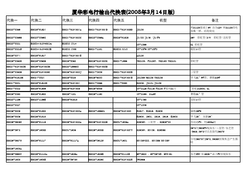
厦华最新行包代换表
BSC29-3937
BSC29-N1105
BSC29பைடு நூலகம்3966
BSC29-3980
BSC29-01N4087F
S293、S2916.S34L、S3417
BSC29-3987 BSC29-3984N BSC29-3958 BSC29-3964X BSC29-3967 BSC29-N1103A BSC29-3911N BSC29-N1124 BSC29-3974 BSC29-01N4087H BSC29-3957 BSC29-3983N BSC29-3934 BSC26-3905 BSC29-3991B BSC29-3918
永新管、动态FV、三FV 极/在1929A产品 上FV引线加长 三星管、50HZPF 东芝管PF/永新DC01
BSC29-3936
BSCN29-N1106
BSC29-01N4087G
BSC29-01N4087B
XT-29FA、XT-2990
BSC26-N1007 BSC29-N1124
BSC29-3971 BSC29-174902
MT-2968C 三星单FV管 TN2985/TC3468 三星 有动态FV,单聚焦/ 100HZ三轴FV,FV线 双FV管、 加长/ TC2968永新双聚焦管/TN3483 如果有机器用1938B行包,彩电出现关机彩 斑,把BSC31-1938B直接更换成BSC311936A就好
BSC31-1938B
BSC29-01N4004F(-32) BSC28-N2302A BSC29-3914B BSC29-3927B BSC29-1927A BSC29-N1129C BSC29-3943 BSC29-3982N BSC29-3994B BSC29-N1111 BSC29-2927B BSC29-3794 BSC29-01B28 BSC29-01N4087I
9833D 24W LED驱动应用替换BP2833参考
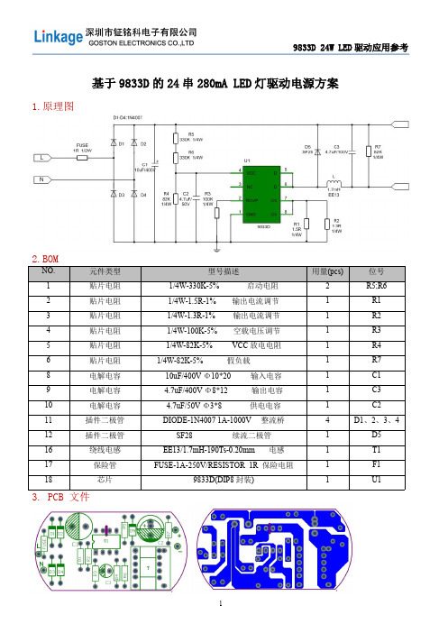
基于 9833D 的 24 串 280mA LED 灯驱动电源方案
1.原理图
2.BOM
NO.
元件类型
1
贴片电阻
2
贴片电阻
3
贴片电阻
4
贴片电阻
5
贴片电阻
6
贴片电阻
8
电解电容
9
电解电容
10
电解电容
11
插件二极管
12
插件二极管
16
绕线电感
17
保险管
18
芯片
3. PCB 文件
9833D 24W LED 驱动应用参考
76 V/50Hz;满载
200V:满载
220 V/50Hz;满载 580mV
264V/50HZ 满载 580MV
5
VDS V schottky工作波形
9833D 24W LED 驱动应用参考
176 V AC 满载
200V AC/满载
220V V AC/满载
264V AC/满载
6
240V 0.363W
17.5V 0.316 6.86 80.61 0.321 7.03 79.90 0.320 7.07 79.21 0.325 7.20 79.00 0.326 7.23 78.91
264V 0.420W
开路保护
开路保护 OK 开路电压 22-25V
常温、高温老化测试
测试条件
93 28% 92.87%
283.9 284.4
100
90
30.54 27.66
92.96% 92.52%
287.0 80
24.72 92.88% 286.5
昂宝与茂捷半导体产品替换表

的T5、T8灯管等中大 元器件少
功率LED电源
④可进模拟与PWM调
光
24W-32W,30W-42W,36W-48W,45W-56W
◆LED驱动 隔离驱动+PFC+内置MOS
芯片简要说明
产品方案特点
应用行业
常用案例
PSR+PFC,内置MOS
高PFC值,PSR系列,省光耦和431,节省 成本空间,安全性高。
GR8830,OB2269(管脚不容),SD4872(脚 位不兼容),SP5875(管脚不容),
SP5876(管脚不容),LD7575(管脚不 容),LD7576(管脚不容)
SSR+外置MOS管,各种保护功能
SSR电压电流精度高, M5576最大待机功 耗〔100mW〕 高效率:〔24V5A平均效率
待机功耗<100mW,抖频功能,65KHz,高性 能PWM控制器,欠压保护
1:高要求的手机充 电器
2: 适配器(笔记本适 配器、MID充电器、
显示器电源 3: LCD TV电源。
① 开关频率可调 ② 待机空耗低 ③ 比OB2273 /2263
性价比更高 ④ 容易过EMI ⑤相同变压器的情况 下可以做更大功率
PSR内置MOS有线补功能,各种 保护功能
PSR成本低,节省PCB板上空间,省掉光 耦和431,节省成本
① 输出电压精度
手机,移动电源, 高,OCP保护一致性
MID充电器,理发 好
②
剪,按摩器,适配器
待机空耗低
等
③ 比OB2538性价比
更高
OB2536,CR6236,RM3262 SP5618,SF5926,ME8302 HT2356,PN8326,LY2926
常用集成芯片
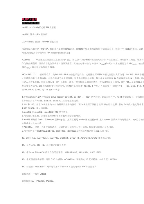
常用芯片作用2007-07-30 16:40mc2831(mc2833)低功耗FM发射机mc3362低功耗FM接收机CXA1691BM收音机FM/AM接收芯片双音频编码器件是HM9187,解码芯片是MT8870(注意:HM9187输出的双音频信号幅值太大了,串联一个160K的电阻,送到M 幅度,幅度过高会导致窄带FM的调制/解调出问题.)ICL8038 单片集成压控波形发生器(应用广泛),在0.01~300kHz的范围里可以同时产生正弦波、矩形波和三角波。
使用时只作为压控振荡器、调频信号发生器或单片函数发生器。
其输出电平特性为:方波0.2V suppl y(2mA);三角波幅度为0.33V suppl y,输出阻22V supply,输出阻抗典型值为1kΩ。
MC145151 -2 锁相环芯片,是MC145151-1的性能改进产品,功耗降低而ESD和锁定性能则大有改进。
MC145151-2分别用N计数器和R计数器编程。
本器件集成了参考振荡器、可选参考频率分频器、数字相位鉴相器和14位可编程的除N计数器。
该芯工艺而具有低功耗,电压范围为3~9V;具有片上或离片参考振荡器的操作条件;有两路鉴相信号输出,其中PD out是鉴相器A的是鉴相误差信号,LD用来输出相位锁定信号;除N的范围为3~16383;8个用户可选的除R值分别为8、128、256、512、1应RA2~RA0从000到111的8个状态。
1.音频pcm编码DA转换芯片cirrus logic的cs4344,cs4334 。
4334是老封装,据说已经停产,4344封装比较小,非常好用2.音频放大芯片4558,LM833,5532,此二芯片都是双运放。
3.244和245,由于244是单向a=b的所以只是单向驱动。
而245是用于数据总线等双向驱动选择。
同时245的封装走线非常适4.373和374,地址锁存器,5.max232和max202,max3232 TTL电平转换6.网络接口变压器。
ATBM8831DTMB解调芯片介绍

ATBM8831DTMB解调芯片介绍
ATBM8831 DTMB 解调芯片介绍
ATBM8831 是高拓讯达公司于2009 年第二季度发布的单芯片DTMB(中国数字电视地面波传输系统标准)解调芯片,遵循中国国标GB20600-2006《数字电视地面广播传输系统帧结构,信道编码和调制》,支持单载波和多载波模式的解调,同时支持标清和高清电视信号的地面波接收。
该芯片有着优异的灵敏度和抗干扰能力,可以广泛用于室内和室外的固定及移动应用。
ATBM8831 主要针对便携设备、USB 电视棒和手持终端等设计。
该芯片接收来自地面波电视天线的模拟基带、低中频或高中频输入,输出所选定频道的传输流信号(AVS、MPEG2、MPEG4 或H.264 等)。
接收机的典型结构
ATBM8831 芯片系统架构
功能特点
·完全符合国标
-支持DTMB(中国数字电视地面波传输系统标准)的单载波和多载波模式;
-出色的回波多径处理算法,实现在单频网环境中领先的抗干扰性能;
-快速锁定频率,实现高速搜台和迅捷换台;
-优异的单、多载波高速移动接收性能;
-超低功耗,实现低发热连续工作;
-简易的软件驱动设计,非常易于移植和集成。
·模拟部分
-集成10-bit 模数转换器;
-集成锁相环;
-支持频率范围为28~32MHz 的晶体。
CSC8932完全替换BP2831A
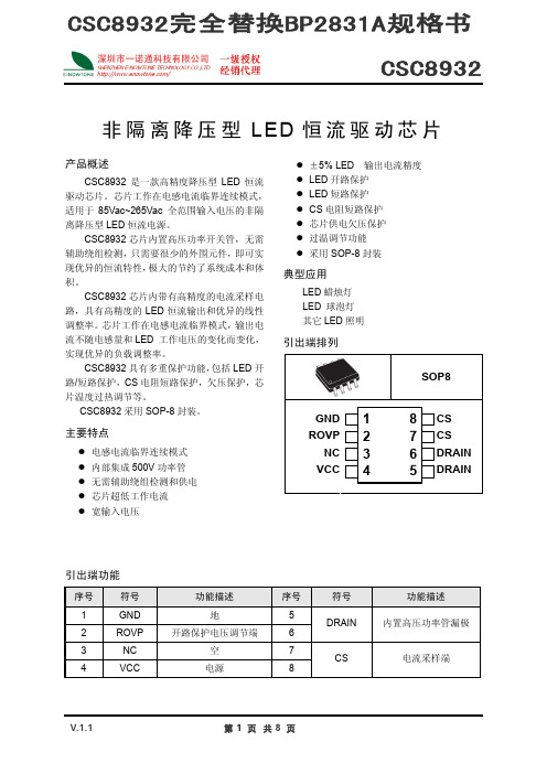
恒流控制,输出电流设置
芯片逐周期检测电感的峰值电流,CS 端连接到内部的峰值电流比较器的输入端,与内部 400mV 阈值电压进行比较,当 CS 电压达到内部检测阈值时,功率管关断。 电感峰值电流的计算公式为:
其中,RCS 为电流采样电阻阻值。
I PK
=
400 (mA) RCS
LED 输出电流计算公式为:
CSC8932完全替换BP2831A规格书 CSC8932
非隔离降压型 LED 恒流驱动芯片
产品概述
CSC8932 是一款高精度降压型 LED 恒流 驱动芯片。芯片工作在电感电流临界连续模式, 适用于 85Vac~265Vac 全范围输入电压的非隔 离降压型 LED 恒流电源。
CSC8932 芯片内置高压功率开关管,无需 辅助绕组检测,只需要很少的外围元件,即可实 现优异的恒流特性,极大的节约了系统成本和体 积。
功能说明
CSC8932 是一款专用于 LED 照明的恒流驱动芯片,应用于非隔离降压型 LED 驱动电源。芯 片内部集成 500V 功率开关管,只需要极少的外围组件就可以达到优异的恒流特性。而且无需辅助 绕组供电和检测,系统成本极低。
启动
系统上电后,母线电压通过启动电阻对 VCC 电容充电,当 VCC 电压达到芯片开启阈值时,芯 片内部控制电路开始工作。CSC8932 内置 17V 稳压管,用于钳位 VCC 电压。芯片正常工作时,需 要的 VCC 电流极低,所以无需辅助绕组供电。
(2) 无特殊说明,所有的电压以 GND 作为参考。
V.1.1
第2 页 共8 页
CSC8932
电气参数(无特别说明情况下,Vcc=15V,TA=25℃)
符号
参数
测试条件
各种电脑块超级单片及各种集成电路IC的代换收集

创维东芝超级单片机使用的微处理器的代用关系创维东芝超级单片机心有:3T30、4T30、5T30、3T36、4T36、5T36等机心,是创维公司与日本东芝公司联合开发的新一代超级单片集成电路彩电机心。
该机心采用了东芝公司最新推出的超大规模集成心片,有:TMPA8803CSN、TMPA8823CSN、TMPA8808CSN、TMPA8809CSN、TMPA8829CSN等。
在创维东芝超级单片机心中,3T30、3T36、4T36是同一种机心,使用的软件基本相同,对应的超级单片型号是’rMPA8803CSN或者TMPA8823CSN。
TMPA8823CSN是TMPA8803CSN软件升级后的版本,但二者配套使用的存储器不同,不能互换使用。
4T30、5T36、5T30是同一种机心,使用的软件基本相同(电源电路不同),对应的超级单片型号是TMPA8808CSN、TMPA8809CSN或者TMPA8829CSN。
TPMA8829C8N是TMPA8809CSN软件升级后的版本,其存储器的代换原则配套使用的存储器不同,不能互换使用。
创维的83703可代8370183735可代83702和837325P30的83731没有可代换的。
83703还能带83702,但是会出现无声或者白屏把OP2调成28即可。
创维T系列机型CPU的代换目前T系列机芯共有5种CPU,其分别为:1、87CM38N-3856,在3T01、4T01机芯上使用,其可存储100个频道。
2、87CM38N-1N86,在21寸9000系列机芯上使用,可存储256个频道,并带有游戏功能。
3、87CM38N-1N10,在25寸5T10机芯上使用,可存储228个频道。
4、87CM38N-1R02,在29寸5T10、5T20机芯一使用,可存储256个频道,带有游戏功能。
5、87TPS38N,此种为OTP产品,为T系列最早使用的CPU,在25寸5T10机芯上使用,有两种,其分别为可存储228和256个频道。
彩电用声表面滤波器型号与代换

彩电用声表面滤波器型号与代换电材料制成的基片及烧制在其上面的梳状电极所构成。
当给声表面波滤波器输大端输入信号后,在电极司压电材料表面将产生与外加信号频率相同的机械振动波。
该振动波以声波速度在压电基片表面传播,当该波传至输出端时,由输出端梳状电极构成的换能器将声能转换成交变电信号输出。
图1 声表面波滤波器结构示意图从上面介绍不难看出,声表面波滤波器是由两个换能器组成的,输入端换能器将电能转换成声能发出声表面波,而输出端换能器则是将接收到的声表面波声能转换成电能输出。
声表面波滤波器就是利用压电基片上的这两个换能器来产生声表面波和检出声表面波的,以完成滤波的作用。
一、声表面波滤波器的测量如图1所示,无论哪种声表面波滤波器,其输入电极的叉指对(①、②脚)、输出电极的叉指对(②、④脚)以及输入、输出叉指对之间都是绝缘的、即是说它们之间的电阻值应是∞的.并且每一个电极与屏蔽接地脚问的电阻值也应是无穷大的。
根据这一特点,我们便可用万用表对其进行性能测量。
如图2所示,将万用表置R×1k(或×10k)档,分别测量输入脚①、②脚、输出脚②、④脚之间和输入、输出脚对屏蔽脚⑤之间的电阻值,如果表针在最大处不动,表明这只声表面滤波器是好的,可以便用;如果表针有摆动,指示在数十千欧或数百干欧,则表明声表面滤波器有漏电现象,一般不能使用;如果表针指示很小或为零,则表明声表面滤波器已击穿短路,不能使用。
图1声表面滤波器的结构图2声表面滤波器的测量示意图二、声表面滤波器的检修与维修由于声表面波滤波器的叉指电极之间距离很小,在使用中会被击穿而造成短路,再就是声表面滤波器内部压电材科上的金属膜部分容易漏电或短路,所以声表面滤波器最常见的故障就是漏电或击穿短路,只有极少数为内部接触不良或开路。
出现故障时会使图像雪花点多、图像淡,彩色时有时无、噪声大、图像不稳定,严重时出现无图无声,甚至使光栅变得很暗等。
检修方法如下:(一)不在路检修法1、电击修复法(1)中压电击法:从电路上先焊下已损坏的声表面滤波器,用一根导线将声表面的接地脚与电视机机芯“地”连接在—起,然后开机。
非隔离降压型LED恒流电源9833D替换BP2833

其中, IPK 是电感的峰值电流。
toff
L I PK VLED
线电压补偿
储能电感的计算公式为:
5
9833D
L V LED (V IN V LED ) f I PK V IN
保护控制
9833D 内置多种保护功能,包括输出 LED 开路/短路保护,电流检测电阻短路保护和 芯片过温保护。 芯片工作时自动检测负载状态,如果输出 LED 开路/短路、电流检测电阻短路或者电 感饱和, 芯片立刻进入短路保护状态, 功率 MOSFET 被关断。同时,芯片不断检测负载 状态, 直到故障解除, 当外部短路故障解除 后,芯片自动恢复到正常工作。 内部过热保护电路检测芯片结温度, 当结温 度超过热保护阈值时, 芯片进入过热保护状 态,功率 MOSFET 立刻被关断,直到结温度 下降 20℃以后,芯片才会退出过热保护状 态,恢复到正常工作。
电气特性参数
(若无特殊说明,TA=25℃,VCC=7.3V)
符号
Vcc_clamp Icc_clamp VCC_ST Vuvlo_HYS Ist Iop Vcs_th TLEB TDELAY TOFF_MIN TOFF_MIN TON_MAX
参数
VCC 钳位电压 VCC 钳位电流 芯片启动电压 欠压保护迟滞 启动电流 工作电流 电流检测阈值 电流采样消隐时间 芯片关断延迟 最小退磁时间 最大退磁时间 最大开通时间 内部开关管导通阻 抗 内部开关管最大耐 压 功率管漏电流 内部基准电压
I LED
I PK 2
其中,L 是电感的感量;IPK 是流过电感的 电流峰值;VIN 是输入交流经整流后的直流 电压;VLED 是输出 LED 上的电压。 当芯片输出脉冲关断时,外部功率 MOSFET 也被关断, 流过储能电感的电流从峰值开始 往下降, 当电感电流下降到零时, 芯片再次 输出脉冲。功率管的关断时间为:
iMX283 Nand Flash更换说明 V1.00
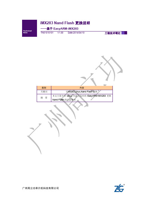
拿到一颗新的 Nand Flash 后,首先要知道类型(必须是 SLC,暂不支持 MLC)、容量、 ID 号,并找到时间数据表。
以 MX30LF1G08AA 为例: 根据手册可知其为 SLC、1Gbit,从“ID Read”小节,其 datasheet 手册 25 页可知,其 Manufacturer ID 为 0xC2,其 Device ID 为 0xF1,其时间数据表在 32 页,如下:
工程技术笔记
©2013 Guangzhou ZLG MCU Technology Co., Ltd. 2
广州周立功单片机科技有限公司
iMX283 Nand Flash 更换说明
——基于 EasyARM-iMX283
3. 修改步骤
3.1 linux、uboot 驱动修改
内核、uboot 中的驱动修改,主要涉及以下两个文件:
3
广州周立功单片机科技有限公司
iMX283 Nand Flash 更换说明
——基于 EasyARM-iMX283
/*512 Megabit */ {"NAND 64MiB 1,8V 8-bit", 0xA2, 0, 64, 0, LP_OPTIONS}, {"NAND 64MiB 3,3V 8-bit", 0xF2, 0, 64, 0, LP_OPTIONS}, {"NAND 64MiB 1,8V 16-bit", 0xB2, 0, 64, 0, LP_OPTIONS16}, {"NAND 64MiB 3,3V 16-bit", 0xC2, 0, 64, 0, LP_OPTIONS16},
bp2831a工作原理

bp2831a工作原理小伙伴们!今天咱们来唠唠BP2831A这个超有趣的东西的工作原理呀。
BP2831A呢,就像是一个超级小管家,专门负责和灯打交道的哟。
你看那些亮闪闪的LED灯,它们能好好发光可离不开BP2831A的功劳呢。
它呀,最主要的工作就是控制电流。
想象一下,电流就像一群调皮的小蚂蚁,要是没有个厉害的角色管着,它们就会到处乱跑。
BP2831A就是那个厉害的角色。
它会把从电源来的电流,按照LED灯需要的量,稳稳地送过去。
比如说,LED灯就像一个个小饿鬼,它们只能吃一定量的“电流食物”,BP2831A就会精准地给它们分配。
BP2831A还有一个很厉害的本事,就是能适应不同的电压情况。
你知道的,电压有时候就像个调皮的小孩子,一会儿高一会儿低的。
可是BP2831A可不会被它搞乱。
当电压高的时候,它就会巧妙地调整自己的工作方式,就像一个聪明的小工匠,把多余的能量巧妙地处理掉,不让LED灯被过高的电压给弄坏。
而当电压低的时候呢,它又会努力地从那一点点电压里挤出足够LED灯用的电流,就像一个特别会过日子的小主妇,一点点资源都能合理利用起来。
这个小芯片内部就像一个小小的工厂呢。
里面有各种各样的电路元件在协同工作。
有负责检测电流大小的部分,就像一个小小的质检员,时刻盯着电流是不是在正确的数值上。
一旦发现电流有偏差,就会马上告诉其他部分。
然后就有像小邮递员一样的电路,把这个消息快速地传递给负责调整电流的部分。
这个调整电流的部分呢,就像一个勤劳的小工人,接到消息后就赶紧动手,把电流调整到合适的数值。
而且呀,BP2831A还特别注重安全呢。
它就像一个细心的小保镖,时刻保护着LED 灯和整个电路系统。
如果有什么异常情况,比如说电流突然变得超级大,就像一群发狂的小怪兽冲过来一样,BP2831A就会迅速做出反应。
它会切断电流,不让这个大麻烦继续蔓延,就像小保镖勇敢地挡住了危险,保护了后面的一切。
在实际的灯具应用中,BP2831A可真是个大明星呢。
FM发射电路图

FM发射器电路——全集本电路图所用到的元器件:BBC109C电路如图所示。
它包括红外传感头、电子开关、音响发声电路、无线FM电路等。
将它安装在银行、密室或库房等需要监护的场所,用于晚上代替人员值守,当有人潜入作案时,电路将自动发出调频(FM)无线报警信号,附近(500m)的值班人员从FM收音机中可收到“呜呜……”作响的报警信号.从而采取积极的防范措施。
高频发射管D40揭密最早的关于"D40"文章从电路明显可以看出电路还较简易,不够完善,但这篇文章的历史意义要远远大于他的实际制作意义,我想也是这篇文章给了业余调频发烧友一个美丽的梦。
晓吴:这是一篇刊登在《家电维修》1992年第7期上的文章,名叫《超远程无线话筒》,作者是李栋鑫,说是能在开阔地最远可以发射1.5kM。
我看到这篇文章是在95年还是96年的时候,当时我真的对这管子是日思夜想,千方百计的想买到这个神奇的管子,但几年后我终于明白了些什么…………D40 这个管子最早初现在1992年《家用电器》刊登的一篇《超远程调频无线话筒》文章提到的,文章发表后,无线电爱好者无不为它神往,但确苦于没D40的参数,无法制做,正在吊足所有人胃口时,巧在这时,半年后又一篇《超远程调频无线话筒》一文答读者见刊,声称D40为特殊新型产品,并提供了该管的性能指标:D40 管是台湾敏通公司的产品,进口时型号已被抹去,电气参数BVCE0>9V、ft>280MHz、PCM:1W、ICM:150mA、β>120,声称据他们了解国内市场目前是不可能有买或替代品,只有他们有货可供,12.5元/只(相当与一只2SC1971的价)。
几年来,圈内又相继出现了所谓发射距离更远的D50的精品发射管,一时间电子报刊与网上有供D40、D50的信息漫天飞,,无意例外他们的价格都高的离谱,甚至我还看到了声称可以发射5公里的发射管D60的广告,我的天那!但是到你经过千方百计真的把那些所谓的D系列弄到手时,你却发现并不像传说的那样好使,为什么哪?当你仔细观察这些D管是它们不是被打磨掉了原有型号就是又被重新印是了D40、D50的字样,没见有人买到过真正用激光印有D40的管子。
HA5832E 非隔离替代BP2832A

范围 15.8~17.2 ≦135 12.8~14.2 ≦195 8.1~9.1 392~408 198 500 150
单位 V μ A V μ A V mV mV ns ns V Ω uA V us us us ℃
VGS=0V/ IDS=250uA VGS=15V/ IDS=0.5A VGS=0V/ VDS=500V
符号 VDD_CLP IDD VST IST VUVLO VISEN VISEN_SHT TLEB TDELAY VDSS (BV) RSW IDSS VRADJ TON_MAX TOFF_MAX TOFF_MIN TREG
测试条件 0.8mA FSYS=65KHz VDD 上升 VDD=VST - 1V VDD 下降 输出短路
开路过压保护电阻设置
在系统中,当LED开路时,由于无负载连接,输出电压会逐渐上升,进而导致退磁时间 也会逐渐变短, 因此通过RADJ外接电阻来控制相应的退磁时间, 就能得到需要的开路保护电 压。根据内部电路计算,可得出RADJ与VOVP的关系公式:
-5-
HA5832E
R ADJ VISEN L 15 RISEN VOVP 10 6 ( Kohm)
revisionhistoryrevisionreleasedatadescriptionha5832e概述ha5832e是一款高精度的非隔离降压型led控制器防闪烁适用于85v265v全电压范围的小功率非隔离降压型led照明应用ha5832e内置了高精度的采样补偿电路使得电路能够达到5以内的恒流精度并且能够实现输出电流对电感与输出电压的自适应从而取得优异的线型调整率和负载调整率ha5832e内部集成了500v功率mosfet无需次级反馈电路也无需补偿电路加之精准稳定的自适应技术使得系统外围结构十分简单可在外围器件数量少参数范围宽松的条件下实现高精度恒流控制极大地节约了系统成本和体积并且能够确保在批量生产时led灯具参数的一致性ha5832e具有丰富的保护功能
汽车电子常用芯片型号代换资料

汽车电子常用芯片型号代换资料汽车电子常用芯片型号代换资料汽车电子, 存储器标志印字芯片功能代换型号BOSCH3003930061 ADC0809B22AN 存储器 93C06B34AB 存储器 24C02B43AB 存储器 24C02B46AJ 存储器 24C02B49AJ 存储器 24C02B52AP 存储器 24C02B54AH 存储器 24C02B57120 存储器 27C64B57324 存储器 2732AB57347 存储器 27C64B57423 存储器 27C256B57449 74HC74B57477 存储器 27C64B57519 存储器 27C64B57581 74HC573B57604 存储器 27C256B57605 存储器 27256B57607 存储器 27C128B57610 存储器 27C128B57618 存储器 87C257B57618 存储器 87C64B57625 存储器 2764AB57654 存储器 27C256B57701 存储器 27C256B57733 4x位开关 TLE4211, TLE6220 B57764 存储器 87C257 B57764 存储器 87C64B57771 存储器 27C256B57922 存储器 87C257B57960 存储器 27C256B57995 存储器 TMS27C256B58014 存储器 27C256B58038 存储器 27C256B58094 存储器 27C510B58126 存储器 27C010B58127 存储器 27C512B58150 存储器 87C257B58157 存储器 27C512B58185 存储器 87C257B58196 存储器 NS93C46B58234 存储器 27C256B58235 存储器 87C257B58239 存储器 27C512B58240 6 x位开关 TLE4216G, TLE4226GB58241 4 x位开关 TLE4214G, TLE6225B58243 存储器 CJ87BC6QGB58244 I87M12B58258 存储器 24C02B58265 控制器 CAN控制器??B58275 存储器 27C1024B58286 控制器 SAB80C166B58293 存储器 27C512B58331 存储器 28F010B58380 存储器 24C02B58381 存储器 AM28F512B58399 存储器 AM29F010B58400 存储器 87C510B58424 存储器 27C512B58502 ABS,ASR系统IC TLE5200G, TLE6210G B58504 ABS,ASR系统IC TLE5201G, TLE6211G B58505 2 x位开关TLE5225G, TLE6215GB58517 存储器 28F020B58533 存储器 27C4096B58539 存储器 27C256B58541 存储器 27C512B58542 存储器 27C512B58543 存储器 27C512B58544 存储器 27C1001B58545 存储器 87C257B58546 存储器 87C510B58547 存储器 27C1001B58548 存储器 TMS27PC210 = 27C1024B58550 存储器 27C512B58590 AS87C196ENB58637 4 x位开关 TLE5226G, TLE6216GB58639 存储器 87PC110B58732 4 x位开关 TLE5216G, TLE6220B58755 存储器 AM29F200B58768 存储器 AM29F400ABB58791 存储器 AM29F200ABB58813 存储器 93C56B58911 存储器 TMS27C010AB58335 存储器 AT28C64BB58601 存储器 AM29F200BB9411 存储器 AM27C256DELCO08393 功放 TDA7372A96405 功放 TDA7376B9355092 存储器 24C049355093 存储器 24C0816124342 功放 TDA736016175974 RDS解调器SAA6579 16219796 功放TDA7454 100% , not TDA7384 16233541 存储器 M27C256BPIONEERPA2024A 电源 TA8244HPA3002 功放 HA1397PA3005 功放 HA1384PA3027A 功放 HA13150APA3029A 功放 HA13151PA3029B 功放 HA13151PAL001A 功放 TDA7394PAL002A 功放 TDA7394PAL003A 功放 TDA7384APAL005A 功放 TDA7385PAL006A 功放 TDA7560PAL007A 功放 TDA7560PAU001A 功放 HA13151VISTEON0022FBCAC 电源 TL751M100040FBCAC 电源 TL751M1077002 I2C存储器 24C167008FB 电源 78L0570001BB RDS解调器 TDA733070001SE RDS解调器 TDA733070001RR RDS解调器 TDA7330 ??70002FE 音频处理器 TDA731170003AB 功放 TDA200370003SC FREQ. SYNTH.70003SE RDS解调器 TDA733070005EB PLL立体声译码器 TDA159170005EH 音频处理器 TDA7340P70006SE 音频处理器 TDA734070008AB 功放 TDA736070009AB 功放 11 pins70010AB 功放 TDA735070010BB 双运放 TDA342070010FB 电源 TL751M1070011AB 功放 TDA7350with some modifications 70011SB 音频处理器 TDA152470014BB 控制放大器 LM83770016SE 音频处理器 TDA7460N70017AB 驱动放大 TDA723770017FB 电源 TA1483270019SB 音频处理器70023AB 功放 TDA739170024AB 功放 TDA737570024SB 杜比电路 TEA065570025SB AMS LA201070026SB FRONT END70027SB70028SB IF/DET70029SB 音频处理器 TDA730670032AB 前置放大 TDA1523 ??70033BB 控制放大器 LM83770034AB 功放 TDA1519B70039AB 功放 TDA8566Q70042FB 电源 L084, L495370043AB TEA0675 or TDA8586Q70045SB 杜比电路 TEA067570047SB 杜比电路 TEA0675T70052AB 功放 TDA8586Q70082FB 电源70530FB 电源70670FS 前置放大 TEA0676T71005DC LCD显示驱动 PCF857771005TB 多频调制 DS36277N7100130 PCF8576TN700700CFFB000 电源 PHIL, HSOP-20 F2DF-14A652-EA 电源TL751M10SONY159-00 功放 HA13151160-00 功放 HA13151180-00 功放 HA13152260-41 功放 HA13151260-77 功放 HA13150A279-82 功放 HA13151279-87 功放 HA13151279-89 功放 HA13152360-47 功放 HA13153365-41 功放 HA13155368-11 电子音量 LC75372E 369-41 功放 HA13155369-42 功放 HA13153426-49 功放 HA13155448-48 功放 HA13157448-61 功放 HA13156490-48 功放 HA13158PICKUPSOPTIMA-150S JVC OPTIMA-6S KSP-1H KENWOOD KSS-213F RAE0142Z MATSUSHITA RAE0144 1121 SONY KSS-210A KSS-168A SONY KSS-320BKSS-412A SONY KSS-401AKSS-401A SONY KSS-412AKSS-313A SONY KSS-313CKSS-240 SONY KSS-390KSS-314A SONY KSS-313A SOH-AAU SAMSUNG KSS-213KSS-540A SONY KSS-541AKSS-520A SONY KSS-521AMOTOROLAMC13304T3 功放 TA8215MC13306T3S 功放 TA8205MC13309T3 功放 TA8215MC13320T3 功放CHRYSLER 4632512 音频处理器TDA7314S 4651311 功放TDA1553Q4391943 74HC004392073 27C2564392075 74HC144517571 74HC3734517572 74HC74 ??4632511 TDA1591T4632858 TDA3601AQ4632990 M28F1024651350 L9222AOTHERSM851G OKI , 存储器 93C4616811G OKI , 存储器 93C4616911 OKI , 存储器 59C11 ADxxxx YAZAKI, 存储器 93C46 8-bit ABxxxx YAZAKI, 存储器 ER59C11标志印字芯片功能代换型号BOSCH3003930061 ADC0809B22AN 存储器 93C06B34AB 存储器 24C02B43AB 存储器 24C02B46AJ 存储器 24C02B49AJ 存储器 24C02B52AP 存储器 24C02B54AH 存储器 24C02B57120 存储器 27C64B57324 存储器 2732AB57347 存储器 27C64B57423 存储器 27C256B57449 74HC74B57477 存储器 27C64B57519 存储器 27C64B57581 74HC573B57604 存储器 27C256B57605 存储器 27256B57607 存储器 27C128B57610 存储器 27C128B57618 存储器 87C64B57625 存储器 2764AB57654 存储器 27C256B57696 存储器 27C256B57701 存储器 27C256B57733 4x位开关 TLE4211, TLE6220B57764 存储器 87C257B57764 存储器 87C64B57771 存储器 27C256B57808 存储器 27C256B57922 存储器 87C257B57960 存储器 27C256B57995 存储器 TMS27C256B58014 存储器 27C256B58038 存储器 27C256B58094 存储器 27C510B58126 存储器 27C010B58127 存储器 27C512B58150 存储器 87C257B58157 存储器 27C512B58185 存储器 87C257B58196 存储器 NS93C46B58234 存储器 27C256B58235 存储器 87C257B58239 存储器 27C512B58240 6 x位开关TLE4216G, TLE4226G B58241 4 x位开关TLE4214G, TLE6225 B58243 存储器 CJ87BC6QGB58244 I87M12B58258 存储器 24C02B58265 控制器 CAN控制器??B58275 存储器 27C1024B58286 控制器 SAB80C166B58293 存储器 27C512B58331 存储器 28F010B58380 存储器 24C02B58381 存储器 AM28F512B58399 存储器 AM29F010B58400 存储器 87C510B58424 存储器 27C512B58502 ABS,ASR系统IC TLE5200G, TLE6210G B58504 ABS,ASR系统IC TLE5201G, TLE6211G B58505 2 x位开关TLE5225G, TLE6215GB58517 存储器 28F020B58530 存储器 AM29F010B58533 存储器 27C4096B58539 存储器 27C256B58541 存储器 27C512B58542 存储器 27C512B58543 存储器 27C512B58544 存储器 27C1001B58545 存储器 87C257B58546 存储器 87C510B58547 存储器 27C1001B58548 存储器 TMS27PC210 = 27C1024B58550 存储器 27C512B58590 AS87C196ENB58637 4 x位开关 TLE5226G, TLE6216GB58639 存储器 87PC110B58732 4 x位开关 TLE5216G, TLE6220B58755 存储器 AM29F200B58768 存储器 AM29F400ABB58791 存储器 AM29F200ABB58813 存储器 93C56B58911 存储器 TMS27C010AB58335 存储器 AT28C64BB58601 存储器 AM29F200BB9411 存储器 AM27C256DELCO08393 功放 TDA7372A9355092 存储器 24C049355093 存储器 24C0816124342 功放 TDA736016175974 RDS解调器SAA6579 16219796 功放TDA7454 100% , not TDA7384 16233541 存储器 M27C256BPIONEERPA2024A 电源 TA8244HPA3002 功放 HA1397PA3005 功放 HA1384PA3027A 功放 HA13150APA3029A 功放 HA13151PA3029B 功放 HA13151PAL001A 功放 TDA7394PAL002A 功放 TDA7394PAL003A 功放 TDA7384APAL005A 功放 TDA7385PAL006A 功放 TDA7560PAL007A 功放 TDA7560PAU001A 功放 HA13151VISTEON0022FBCAC 电源 TL751M100040FBCAC 电源 TL751M1077002 I2C存储器 24C167008FB 电源 78L0570001BB RDS解调器 TDA733070001SE RDS解调器 TDA733070001RR RDS解调器 TDA7330 ??70002FE 音频处理器 TDA731170003AB 功放 TDA200370003SC FREQ. SYNTH.70003SE RDS解调器 TDA733070005EB PLL立体声译码器 TDA159170005EH 音频处理器 TDA7340P70006SE 音频处理器 TDA734070009AB 功放 11 pins70010AB 功放 TDA735070010BB 双运放 TDA342070010FB 电源 TL751M1070011AB 功放 TDA7350with some modifications 70011SB 音频处理器 TDA152470014BB 控制放大器 LM83770016SE 音频处理器 TDA7460N70017AB 驱动放大 TDA723770017FB 电源 TA1483270019SB 音频处理器70023AB 功放 TDA739170024AB 功放 TDA737570024SB 杜比电路 TEA065570025SB AMS LA201070026SB FRONT END70027SB70028SB IF/DET70029SB 音频处理器 TDA730670032AB 前置放大 TDA1523 ??70033BB 控制放大器 LM83770034AB 功放 TDA1519B70039AB 功放 TDA8566Q70042FB 电源 L084, L495370043AB TEA0675 or TDA8586Q70045SB 杜比电路 TEA067570047SB 杜比电路 TEA0675T70052AB 功放 TDA8586Q70082FB 电源70530FB 电源70670FS 前置放大 TEA0676T71005DC LCD显示驱动 PCF857771005TB 多频调制 DS36277N7100130 PCF8576TN700700CFFB000 电源 PHIL, HSOP-20F2DF-14A652-EA 电源 TL751M10SONY159-00 功放 HA13151160-00 功放 HA13151180-00 功放 HA13152260-41 功放 HA13151260-77 功放 HA13150A279-82 功放 HA13151279-87 功放 HA13151279-89 功放 HA13152360-47 功放 HA13153365-41 功放 HA13155368-11 电子音量 LC75372E 369-41 功放 HA13155369-42 功放 HA13153426-49 功放 HA13155448-48 功放 HA13157448-61 功放 HA13156490-48 功放 HA13158PICKUPSOPTIMA-150S JVC OPTIMA-6SKSP-1H KENWOOD KSS-213F RAE0142Z MATSUSHITA RAE0144 1121 SONY KSS-210AKSS-168A SONY KSS-320BKSS-412A SONY KSS-401AKSS-401A SONY KSS-412AKSS-313A SONY KSS-313CKSS-240 SONY KSS-390KSS-314A SONY KSS-313ASOH-AAU SAMSUNG KSS-213KSS-540A SONY KSS-541AKSS-520A SONY KSS-521AMOTOROLAMC13304T3 功放 TA8215MC13306T3S 功放 TA8205MC13309T3 功放 TA8215MC13320T3 功放CHRYSLER4632512 音频处理器 TDA7314S4651311 功放 TDA1553Q4391943 74HC004392073 27C2564392075 74HC144517571 74HC3734517572 74HC74 ??4632511 TDA1591T4632858 TDA3601AQ4632990 M28F1024651350 L9222AOTHERSM851G OKI , 存储器 93C4616811G OKI , 存储器 93C4616911 OKI , 存储器 59C11 ADxxxx YAZAKI, 存储器 93C46 8-bit ABxxxx YAZAKI, 存储器 ER59C11第1部分汽车音响常用集成电路1.1 收音系统电路1.1.1 AN7222 AM调谐,AM/FM中频放大电路1.1.2 AN7254 FM前端电路1.1.3 AN7463S 带消噪的FM立体声解码器 1.1.4 BA403 FM中频放大器1.1.5 BA1310 锁相环式FM立体声解码器1.1.6 BA1332/BA1332L 锁相环式FM立体声解码器1.1.7 BA1350 带噪声抑制的FM立体声解码器 1.1.8 BA1405/BA1405F FM立体声调制器1.1.9 CX20029 AM/FM立体声收音机电路 1.1.10 CXA1101P/CXA1101M 双通道杜比B型降噪电路1.1.11 CXA1102P/CXA1102M 双通道杜比B型降噪电路1.1.12 CXA1238M/CXA1238S AM/FM立体声收音电路1.1.13 HA11219 FM噪声抑制电路1.1.14 HA12134A 双通道杜比B型降噪电路 1.1.15 KA2244 FM 中频放大器1.1.16 KA2261 锁相环式FM立体声解码器1.1.17 KB4409 锁相环式FM立体声解码器1.1.18 KIA6010SN FM噪声抑制电路1.1.19 LA1130 AM调谐电路1.1.20 LA1132 AM调谐电路1.1.21 LA1135 AM调谐电路1.1.22 LA1140 FM中频放大器1.1.23 LA1175 FM调谐电路1.1.24 LA1862M FM立体声解码器1.1.25 LA2110 FM消噪电路1.1.26 LA3365 锁相环式FM立体声解码器 1.1.27 LA3370 锁相环式FM立体声解码器1.1.28 LA3375 锁相环式FM立体声解码器1.1.29 LA3430 带消噪功能的锁相环式FM立体声解码器1.1.30 LB3500 FM本振频率1/8分频器1.1.31 LC7218/LC7218M/LC7218JM 电子调谐PLL频率合成器1.1.32 LC7219/LC7219M/LC7219JM 电子调谐PLL频率合成器1.1.33 LC72131/LC72131M AM/FM PLL频率合成器1.1.34 LC72146/LC72146M/LC72146V 电子调谐PLL频率合成器1.1.35 LC72191/LC72191M/LC72191JM 立体声电子调谐PLL频率合成器1.1.36 LC72722/LC72722M/LC72722PM 单片RDS信号处理系统1.1.37 LM7001/LM7001M 电子调谐辅助微处理器1.1.38 TA7343AP/TA7343AF 锁相环式FM立体声解码器1.1.39 TA7358P/AP FM调谐电路1.1.40 TA7640AP AM调谐,AM/FM中频放大器 1.1.41 TA8122N/TA8122F 3V AM/FM调谐电路1.1.42 TA8127N/TA8127F 3V AM/FM调谐电路1.1.43 TA8132N/TA8132F AM/FM中放及立体声解码器1.1.44 TA8164P 3V AM/FM收音机电路1.1.45 TC9246F/TC9246P 数字音响锁相环电路1.1.46 TD7104P/TD7104F 数字合成调谐器用ECL预引比例器1.1.47 TDA1579/TDA1579T 交通告警无线传输解码器1.1.48 TEA0652 杜比B/C型降噪电路1.1.49 TEA5560 FM中频放大器1.1.50 μPB553AC 150M Hz低功耗分频电路1.1.51 μPC1167C2 FM中频放大器1.1.52 μPC1171C AM调谐电路1.1.53 μPC1191V AM调谐电路1.1.54 μPC1200V FM中频放大器1.1.55 μPC1215V AM电子调谐电路1.2 磁带放音系统电路1.2.1 AN6263N 磁带暂停检测电路1.2.2 BA338/BA338L 自动选曲电路1.2.3 BA3430S/BA3430F/BA3430FS 带静噪检测的立体声前置放大器1.2.4 BA6219B/BA6219BFP Y 双向电机驱动器1.2.5 BA6285FP/BA6285FS 双向电机驱动器 1.2.6 CXA2509AQ 带选曲功能的均衡放大器 1.2.7 D7784P 双声道磁头选择开关、自动翻转及放大器1.2.8 LA2000/LA2000S 单曲自动选曲电路1.2.9 LB1641 双向电机驱动器1.2.10 LB1649 双桥式电机驱动器1.2.11 LB1836M 桥式电机驱动器1.2.12 MM1322XFBE 电机驱动控制电路1.2.13 TA7291P/TA7291S/TA7291F 电机驱动控制电路1.2.14 μPC1470H 电机速度控制器1.3 音频处理电路1.3.1 AN214 4.4W音频功率放大器1.3.2 AN7168 5.8W×2双通道音频功率放大器1.3.3 AN7178 5.7W×2双通道音频功率放大器1.3.4 AN7310N 立体声双通道音频前置放大器1.3.5 AN7311 立体声双通道音频前置放大器1.3.6 BA328双通道音频前置放大器1.3.7 BA5406 5W×2音频功率放大器1.3.8 CXA1646Q 电子音量控制电路1.3.9 CXA1946AQ 电子音量控制电路1.3.10 HA13001 5.5W×2(BTL 17.5W)音频功率放大器1.3.11 HA13119 5.5W×2音频功率放大器1.3.12 HA13150A 21W×4 BTL音频功率放大器1.3.13 HA13151/HA13151A 14W×4 BTL音频功率放大器1.3.14 HA 13153 15W×4 BTL音频功率放大器 1.3.15 HA 13155 33W×4 B TL音频功率放大器1.3.16 LA2900M 双通道高电平线路放大器1.3.17 LA3160 双通道音频前置放大器1.3.18 LA4440 6W×2(BTL 19W)音频功率放大器1.3.19 LA4445 5.5W×2音频功率放大器1.3.20 LA4743B 45W×4(BTL 19W)音频功率放大器1.3.21 LA47501 50W×4(BTL 19W)音频功率放大器1.3.22 LC7538NM 电子音色控制电路1.3.23 LC75373ED 电子音量控制电路1.3.24 LC75383ED 电子音量控制电路1.3.25 M51522AL 双通道音频前置放大器1.3.26 TA7227P 5.5W×2音频功率放大器 1.3.28 TA7240P/TA7240AP 5.8W×2音频功率放大器1.3.29 TA7270P 5.8W×2音频功率放大器 1.3.30 TA7325P 双通道音频前置放大器。
茂捷半导体方案解决资料

OB2535可以被M5835替换吗?可以的,M5835是一种高性能离线式PWM控制器,主要用于中小功率AC/DC充电器和适配器中。
它工作于原边采样和调节,可省除极间光耦和TL431,其恒压和恒流控制特性说明如下图。
最大输出功率可达15W。
在恒流控制时,其电流和输出功率的设定可由SEN脚上的电流取样电阻Rs来调节;在恒压控制时,利用混合工作模式可以获得高效率和高性能。
另外,利用内部的导线压降补偿功能可以得到良好的负载调整特性。
在恒流模式重负载工作条件下,器件工作在PFM模式,中负载和轻负载,器件可工作在PWM模式和降频模式。
HT2358被M5838替换的优势是什么?M5838是一种高性能离线式PWM控制器,主要用于中小功率AC/DC充电器和适配器中。
M5573控制芯片全电压输入范围内恒压恒流精度均能保持在±5%以内。
M5573控制芯片采用原边反馈技术,使系统应用中可以节省TL431和光耦以降低成本。
特征全电压范围内,恒压调节精度误差<5%,恒流调节精度误差<5%原边采样和调节,无需光耦和TL431可编程CV和CC调节可设定恒流和输出功率内置原边反馈恒流控制内置自适应峰值电流调节内置原边变压器电感补偿可外部调整的输出线压降补偿开机软启动内置MOS开关管内置前沿消隐电路(LEB)可逐周期电流限制带有回差的欠压锁定(UVLO)VDD过压保护(OVP)VDD箝位功能PN8326可替换MOJAYM5836吗?性能、优点是怎样的?可以的,M5836是一种高性能离线式PWM控制器,主要用于中小功率AC/DC充电器和适配器中,芯片最大输出功率可达15W。
M5836具有电源软启动控制和多种带自动恢复的有效保护,它包含逐周期电流限制、VDD过压保护、VDD箝位和欠压保护等。
另外,M5836还有优良的EMI性能和频率抖动控制特性,使用M5836可获得高精确的恒压恒流特性。
MOJAY(茂捷)M5836优势/特点:1.全电压范围CV精度保持在±5%以内2.原边反馈技术可使系统节省TL431与光耦3.可编程的CV/CC4.内置原边绕组电感补偿5.可编程的输出线降压补偿6.内置软启动功能7.内置前沿消隐电路(LEB)8.频率抖动9.逐周期过流保护10.VDDOVP保护功能及VDD电压嵌位功能11.封装方式:SOP-8/DIP-8SY5814非隔离LED驱动替换型号M8914是怎样的?M8914可以替换SY5814,M8914是一款应用于LED照明的单级有源功率因数校正的降压型AC-DC恒流控制器,能够实现高功率因数和精准的输出电流。
- 1、下载文档前请自行甄别文档内容的完整性,平台不提供额外的编辑、内容补充、找答案等附加服务。
- 2、"仅部分预览"的文档,不可在线预览部分如存在完整性等问题,可反馈申请退款(可完整预览的文档不适用该条件!)。
- 3、如文档侵犯您的权益,请联系客服反馈,我们会尽快为您处理(人工客服工作时间:9:00-18:30)。
概述
M8831 是一款高精度降压型 LED 恒流驱动芯片。
芯片工作在电感电流临界连续模式,适用于85Vac~265Vac 全范围输入电压的非隔离降压型LED 恒流电源。
M8831 芯片内部集成500V 功率开关,采用专利的
驱动和电流检测方式,芯片的工作电流极低,无需辅助绕组检测和供电,只需要很少的外围元件,即可实现优异的恒流特性,极大的节约了系统成本和体积。
M8831 芯片内带有高精度的电流采样电路,同时采用了专利的恒流控制技术,实现高精度的 LED 恒流输出和优异的线电压调整率。
芯片工作在电感电流临界模式,输出电流不随电感量和 LED 工作电压的变化而变化,实现优异的负载调整率。
M8831 具有多重保护功能,包括 LED 开路/短路保护,SEN 电阻短路保护,欠压保护,芯片温度过热调节等。
典型应用特点
⏹电感电流临界连续模式⏹内部集成500V 功率管
⏹无需辅助绕组检测和供电⏹芯片超低工作电流
⏹宽输入电压
⏹±3% LED 输出电流精度⏹LED 开路保护
⏹LED 短路保护
⏹SEN 电阻短路保护
⏹芯片供电欠压保护
⏹过热调节功能
⏹采用SOP-8 封装
应用
⏹LED 蜡烛灯
⏹LED 球泡灯
⏹其它LED 照明
图1 M8831 典型应用图
定购信息
管脚封装
图 2 管脚封装图
管脚描述
极限参数(注1)
注 1:最大极限值是指超出该工作范围,芯片有可能损坏。
推荐工作范围是指在该范围内,器件功能正常,但并不完全保证满足个别性能指标。
电气参数定义了器件在工作范围内并且在保证特定性能指标的测试条件下的直流和交流电参数规范。
对于未给定上下限值的参数,该规范不予保证其精度,但其典型值合理反映了器件性能。
注2:温度升高最大功耗一定会减小,这也是由T JMAX, θJA,和环境温度T A 所决定的。
最大允许功耗为P DMAX = (T JMAX - T A)/ θJA或是极限范围给出的数字中比较低的那个值。
注3:人体模型,100pF 电容通过1.5KΩ电阻放电。
推荐工作范围
电气参数(注4, 5) (无特别说明情况下,V DD =15 V, T A =25 ℃)
注4:典型参数值为25˚C 下测得的参数标准。
注5:规格书的最小、最大规范范围由测试保证,典型值由设计、测试或统计分析保证。
内部结构框图
应用信息
图3 M8831 内部框图
M8831 是一款专用于 LED 照明的恒流驱动芯片,应用于非隔离降压型 LED 驱动电源。
采用专利的恒流架构和控制方法,芯片内部集成500V 功率开关,只需要极少的外围组件就可以达到优异的恒值电压进行比较,当SEN 电压达到内部检测阈值时,功率管关断。
电感峰值电流的计算公式为:
流特性。
而且无需辅助绕组供电和检测,系统成本极低。
I
PK
=
400
(mA)
R
SEN
启动
系统上电后,母线电压通过启动电阻对V DD 电容充电,当V DD 电压达到芯片开启阈值时,芯片内部控制电路开始工作。
M8831 内置17V 稳压管,用于其中,R SEN 为电流采样电阻阻值。
SEN 比较器的输出还包括一个350ns 前沿消隐时间。
LED 输出电流计算公式为:
钳位V DD 电压。
芯片正常工作时,需要的V DD 电流极低,所以无需辅助绕组供电。
I
LED
=
I
PK
2
恒流控制,输出电流设置
芯片逐周期检测电感的峰值电流,SEN 端连接到
内部的峰值电流比较器的输入端,与内部 400mV 阈其中, I PK 是电感的峰值电流。
储能电感
V M8831 工作在电感电流临界模式,当功率管导通 时,流过储能电感的电流从零开始上升,导通时 间为:
Tovp ≈
L ⨯V SEN R SEN ⨯V ovp
t on = L ⨯ I PK
V - V
其中, VSEN 是 SEN 关断阈值(400mV ) IN
LED
其中,L 是电感量;I PK 是电感电流的峰值;V IN 是
经整流后的母线电压;V LED 是输出 LED 上的电压。
Vovp 是需要设定的过压保护点
然后根据 Tovp 时间来计算 Rovp 的电阻值,公式
如下:
当功率管关断时,流过储能电感的电流从峰值开 始往下降,当电感电流下降到零时,芯片内部逻 辑再次将功率管开通。
功率管的关断时间为:
Rovp ≈ 15*Tovp *106
保护功能
(kohm )
t =
L ⨯ I PK M8831 内置多种保护功能,包括 LED 开路/短路保 off
LED
护,SEN 电阻短路保护,V DD
欠压保护,芯片温度过
储能电感的计算公式为:
L =
V LED ⨯ (V IN - V LED )
f ⨯ I PK ⨯ V IN
其中,f 为系统工作频率。
M8831 的系统工作频 率和输入电压成正比关系,设置 M8831 系统工作 频率时,选择在输入电压最低时设置系统的最低 工作频率,而当输入电压最高时,系统的工作频 率也最高。
M8831 设置了系统的最小退磁时间和最大退磁时 间,分别为 4.5us 和 240us 。
由 t OFF 的计算公式可 知,如果电感量很小时,t OFF 很可能会小于芯片的 最小退磁时间,系统就会进入电感电流断续模式,
LED 输出电流会背离设计值;而当电感量很大时,
t OFF 又可能会超出芯片的最大退磁时间,这时系统
就会进入电感电流连续模式,输出 LED 电流同样
也会背离设计值。
所以选择合适的电感值很重要。
过压保护电阻设置
开路保护电压可以通过 ROVP 引脚电阻来设置, ROVP 引脚电压为 0.5V 。
当 LED 开路时,输出电压逐渐上升,退磁时间变 短。
因此可以根据需要设定的开路保护电压,来 计算退磁时间 Tovp 。
热调节等。
当输出 LED 开路时,系统会触发过压 保护逻辑并停止开关工作。
当 LED 短路时,系统工作在 5KHz 低频,SEN 关断阈 值降低到 200mV ,所以功耗很低。
当有些异常的情 况发生时,比如 SEN 采样电阻短路或者变压器饱和, 芯片内部的快速探测电路会触发保护逻辑,系统 马上停止开关工作。
系统进入保护状态后,V DD 电压开始下降;当 V DD 到 达欠压保护阈值时,系统将重启。
同时系统不断 的检测负载状态,如果故障解除,系统会重新开 始正常工作。
过温调节功能
M8831 具有过热调节功能,在驱动电源过热时逐
渐减小输出电流,从而控制输出功率和温升,使
电源温度保持在设定值,以提高系统的可靠性。
芯片内部设定过热调节温度点为 150℃。
PCB 设计
在设计 M8831 PCB 时,需要遵循以下指南: 旁路电容
V DD 的旁路电容需要紧靠芯片 V DD 和 GND 引脚。
ROVP 电阻
开路保护电压设置电阻需要尽量靠近芯片 ROVP 引脚。
地线
电流采样电阻的功率地线尽可能短,且要和芯片的地线及其它小信号的地线分头接到母线电容的地端。
功率环路的面积
减小功率环路的面积,如功率电感、功率管、母线电容的环路面积,以及功率电感、续流二极管、输出电容的环路面积,以减小EMI 辐射。
NC 引脚
NC 引脚必须悬空以保证芯片引脚间距离满足爬电距离
DRAIN 引脚
增加DRAIN 引脚的铺铜面积以提高芯片散热。
封装丝印描述。
