PMAC802说明书(液晶版本)-新
SmartPM配电及漏电系统集成配置和对应功能说明

馈线
馈线
PMAC503M4/8智能型漏电火灾探测器
主要功能:测量4/8回路漏电电流及1回路温度; 开关量输入(1路);继电器输出(1路); 数码管显示; RS485通讯。
适用范围:配电箱多回路漏电测量
适用范围:高压柜、进线柜、联络柜及馈线柜
适用客户-PMAC600及PMAC700系列
PMAC625系列三相交流电力仪表,多种型号可供选择, 面板安装,可插拔式端子排,适用于正常配置
PMAC720多功能电力监控仪功能齐全,面板式安装, 拆装更换麻烦,主要适用于新建项目
PMAC725多功能电力监控仪表功能齐全,面板式安装, 可插拔式端子排,主要适用于新建项目和优质客户
PMAC503M4/8漏电火灾探测器功能简单,面板式安装, 主要适用于多回路漏电测量项目
电力仪表简介-PMAC615系列
馈线
馈线 馈线
PMAC615系列数显仪表
主要功能:可测量单相U、I、P、Q、PF、 Hz、KWh等(由仪表的具体型号决定); 数码管显示 选配功能:开关量输入(2路);继电器输 出(1路);RS485通讯 适用范围:馈线柜等
电力仪表简介-PMAC625系列
馈线
馈线 馈线
PMAC625系列三相交流数显仪表
主要功能:可测量U、I、P、Q、PF、Hz、 KWh、Kvarh等(由仪表的具体型号决定); 数码管显示 选配功能:开关量输入(2路);继电器输 出(2路);RS485通讯 适用范围:馈线柜及电容补偿柜等
电力仪表简介-PMAC720系列
主要功能:测量单回路漏电电流及箱体内温度; 开关量输入(2路);继电器输出(1路);支 持消防联动;数码管显示; RS485通讯。
pmac第一、二、三章 用户指导
第一章用户指导PMAC综述Deltu Tau Data System公司的可编程多轴运动控制卡Ⅱ型(PMAC2),是一个高性能伺服运动控制器,通过数字信号处理器(DSP),以及灵活的高级语言最多可控制八轴同时运动。
PMAC2给多轴控制器提供前所未有的性价比,Motorola的DSP56002是PMAC2的CPU,处理所有八轴的计算。
PMAC2有六种类型的板卡,PMAC2 – PC,PMAC2 – PC ultralit,PMAC2 – Lite,PMAC2 – VME,PMAC2 – VME ultralite和MINI PMAC2,这些卡在外型,总线接口形式和I / O端口的性能方面彼此各不相同。
所有这些形式的卡都有相同的在板固件,所以PMAC20的固件程序可以在其它任何形式的板卡运动。
任何形式的PMAC2型板既可以脱机运行,又可以通过串行或总线接口用一台主机来控制它运行。
适应能力作为一种具有广泛用途的控制器,PMAC2能用于各种各样的设备,从那些精密到小于百万分之一英寸的精密仪器到那些需要数百千瓦或马力的大型设备,它的多种用途包括机器人、机床、木工机械、装配线、食品加工、印刷、包装、物料装卸、摄像机控制、自动焊接、硅片加工,激光切割以及许多其他运动控制。
为一个任务的配置PMAC2可以通过硬件设置的选择(通过选件和备件),参数的设置和运动及PLC程序的编写,从而实现一种特殊用途。
每一个PMAC2固件能够控制八个轴。
这八个轴可以相互联致力以完成一个复杂的运动。
每一个轴也可以分别在各自坐标系中独立运动,从而得到八个完独立的运动。
或者在它们之间组合的形式。
PMAC2的CPU与轴的通信是通过特殊设计的门阵列ICs(作为DSPGATE而提到的)来实现,每一个ICs能够控制四个模拟输出通道,四个作为输入的编码器,和四个来自附件的模拟驱动输入,一个PMAC2可以运用一到四个门阵列ICs,从而规定硬件的配置总数,以便统计输入和输出的数量和类型,最多可以有16块PMAC2卡完全同步级链在一起使用,控制总128根轴。
APC802说明书-供参考

深圳市安美通科技有限公司DVER 2.20APC802-43 多通道微功率嵌入式无线数传模块APC802-43模块是高度集成半双 工微功率无线数据传输模块,其嵌入高 速单片机和高性能射频芯片。
创新的采 用高效的循环交织纠检错编码,抗干扰 和灵敏度都大大提高,最大可以纠24 bits连续突发错误,达到业内的领先水 平。
APC802-43模块提供了多个频道的 选择,可在线修改串口速率,发射功率, 射频速率等各种参数。
APC802-43 模块能够透明传输任何大小的数据,而用户无须编写复杂的设置与传输程序,同 应用: ● 无线传感器 ● 家庭自动化 ● 无线抄表 ● 自动化数据采集 ● 工业遥控、遥测 ● POS系统,资产管理 ● 楼宇小区自动化与安防 ● 机器人控制 ● 车辆管理 ● 气象,遥感时小体积宽电压运行,较远传输距离,丰富便捷的软件编程设置功能,使之能够应用与非常广泛的领域。
特点:● 3000米传输距离(9600bps) ● 工作频率418-455MHz(1KHz步进) ● 大于100个频道 ● GFSK的调制方式 ● 高效的循环交织纠错编码 ● 灵活的软件编程选项设置 ● USART接口,RS232/RS485可定制。
● 超大的256bytes数据缓冲区 ● 适合大数据量传输● 内置看门狗,保证长期可靠运行APC802-43 模块是新一代的多通道嵌入式无线数传模块,其可设置众多的 频道,步进精度为1Khz,发射功率高达500mW,而仍然具有较低的功耗,体积 50mm x 39.1mm x 7.0mm,非常方便客户嵌入系统之内。
APC802-43 模块创新的采用了高效的循环交织纠检错编码,最大可以纠24bits 连续突发错误,其编码增益高达近3dBm,纠错能力和编码效率均达到业 内的领先水平,远远高与一般的前向纠错编码,抗突发干扰和灵敏度都较大的 改善。
同时编码也包含可靠检错能力,能够自动滤除错误及虚假信息,真正实 现了透明的连接。
802说明书

YCE C6mini快速入门指南安装使用产品前请先阅读本指南,并请保留备用欢迎使用YCE手机!感谢您选择本公司数字移动电话。
POMP C6mini是由强大团队倾情打造,为您提供高品质的移动通信和娱乐体验。
●您可以通过阅读本手册,全面地了解本智能手机的使用,领略其完善的功能和简洁的操作方法。
使用手机前,请仔细阅读全部安全注意事项和本用户手册,以确保安全和正确使用。
●本用户手册中所用的插图仅作为示意用图,可能与手机有所不同,请以你的手机为准。
●本手册中描述的某些服务和功能取决于网络和预定服务。
●收发信息、上传和下载、进行同步和使用定位服务等可能会产生其他费用。
如欲避免产生额外费用,请选择合适的实际收费计划。
有关详细信息,请联系服务运营商。
安全警告和注意事项将手机放在儿童和宠物等接触不到的地方。
以防可能吞下小零件导致窒息或发生危险。
安全开机,当禁止使用手机或手机的使用会引起干扰或危险时,请不要开机。
请遵守当地的所有相关法律法规。
请使用双手驾驶汽车。
开车时使用手机应首先考虑交通安全。
所有的无线设备都可能受到干扰,从而影响性能。
在医疗或卫生保健机构可能会使用对无线频率敏感的设备。
在飞机上应关机。
请遵守任何的相关的限制规定。
无线设备会对飞机产生干扰。
在加油站或靠近燃料、化学制剂的地方,请不要使用手机。
注意:●您的手机只能使用本公司指定的电池和充电器。
使用其它的产品可能会造成电池漏液、过热、爆裂和起火。
●请使用220V交流电。
使用其它电压会引起漏电、起火和对手机及充电器的损坏。
●禁止短路充电器,否则会引起触电、冒烟和对充电器的损坏。
●请不要在电源线损坏的情况下使用充电器,否则会导致起火和触电。
●请不要拆卸或改装充电器,否则会导致人身伤害、触电、起火和充电器损坏。
●拔插头时要抓住充电器,拉电源线会损坏电线,引起触电和起火。
●手机、电池和充电器无防水性能,请勿在浴室等高湿度的地方使用,同样也要避免被雨淋湿。
●用柔软的干布清洁手机、电池和充电器。
PMAC800系列产品使用手册

适用范围 重要电动机的综合保护 普通电动机的综合保护 普通电动机的电流保护 普通电动机的电流保护
SCT型号 SCT150 SCT200 SCT300 SCT400
电动机额定电流 150A及以下 200A及以下 300A及以下 400A及以下
PMAC系列产品主要特点
● PMAC系列智能电动机保护控制装置是针对低压电动机控制系统设计,超小外型尺寸,适用于GCK、GCS、GGD、 MNS等各种抽出式(包括1/4抽屉)、固定式及混合式的柜型安装。具有方便安装、布局合理、维护方便、节约电 缆、安全可靠等多种优点;
● 全面采用嵌入式 SOC(System On Chip 片上系统)设计、32 位 DSP(Digital Signal Processing 数字信号处理 技术和冗余现场总线技术,交流采样采用优化全波 FFT(Fast Fourier Transform 快速傅立叶变换)技术,软件 采用模块化、高抗干扰设计;
绝缘性能 绝缘电阻 工频耐压 冲击电压 耐湿热
各电气回路之间>20MΩ 各电气回路对地>20MΩ 各电气回路之间2KV/50Hz 1Min 各电气回路对地2KV/50Hz 1Min 各电气回路之间1.2/50μs, 5000V 各电气回路对地1.2/50μs, 5000V 遵循GB/T 2423.9-2001
PMAC系列智能电动机保护控制装置主要用于690V以下低 压电动机控制系统,对电动机的过负荷、短路、超长时间启 动、堵转、不平衡、接地、欠压、过压、工艺联锁等故障引 起的危害予以保护,并集合全面的三相电量测量/显示、数 字输入/输出与网络通讯于一身。每个装置具有多种综合电 力参数测量功能,既可单独作为电测仪表使用,亦可作为电 力综合自动化监控系统之前端,可实现测量、监视、保护、 控制等综合功能,通过其标准的RS-485通讯接口及双绞线网 络与监控系统通信,轻松实现数据的远方管理及“四遥”功 能。
Amico Beds ICU Series B-E-AC802 操作维护手册说明书

Operation & Maintenance Manual ICU Series B-E-AC802 BedTable of ContentsIntended Use 3 Introduction 3 Description of Symbols 3-4 Warning and Caution 3Caught Hazard Warning 3 Features 5 Warnings 6 Specifications 7 Siderail Controls 8 Scale 9 Quick Reference – Digital Scale Display 9 5th Wheel (Directional Wheel) 10 Removable Headboard/Footboard 10 Installing the Footboard 10 Installing the Headboard 10 Removing the Headboard/Footboard 10 Central Locking System 11 Locking the Bed 11 Unlocking the Bed 11 Using the CPR Release Lever 11 Siderails 11 Lowering Siderails 11 Raising Siderails 11 Electrical 12 Standard Features 12 Troubleshooting 13 Siderail Replacement 14-15 Safety Tips 15-17 Brakes 15 Siderails/Restraints/Patient Monitoring 15 Parts and Accessories 16 Operating Stretcher/Surface Precautions 16 Transport 16 Sleep Surface/Mattress 16 Flammability 16 Spray Washing 17 Preventive Maintenance 17 Cleaning 18-19 Bleach Cleaning Instructions 18 Mattress Cleaning Instructions 18 Warranty 192 Amico Beds Corporation 3The B-E-AC802 bed is intended for patients in the Intensive Care Unit.IntroductionThe B-E-AC802 has been designed specifically to help caregivers assist patients in the Intensive Care Unit. This bed features several features such as chair position, integrated foot extender, fluoroscopic fowler section, removable headboard/footboard, and a battery back-up system.The motions of the B-E-AC802 are achieved by independent DC electric motors. Through controls located on the side rails of the bed allowing positions to be changed. The motors are equipped with overheat protection.This bed offers enhanced mobility capabilities with a standard fifth wheel in the base of the bed. This allows for easier manoeuvrability during patient transport and also helps avoid back injury in the caregivers. The battery back-upsystem provides peace of mind during transportation or unexpected power outages allowing the bed positions to be adjusted accordingly.This Manual provides instructions required for normal operation of the B-E-AC802 bed from Amico Beds Corporation. Prior to operation of this bed, it is important that this manual is read and ensure that all safety aspects contained in this manual are strictly adhered to.Description of SymbolsThis document contains different typefaces and symbols designed to improve readability and increase understanding of its content. The symbol below highlights a WARNING or CAUTION .WARNING AND CAUTIONWARNING: Identifies situations or actions that may affect patient or user safety. Disregarding a warning could result in patient or user injury.CAUTION: Points out special procedures or precautions that personnel must follow to avoid equipment damage.CAUGHT HAZARD WARNINGThis symbol highlights a CAUGHT HAZARD WARNING .Intended UseDescription of Symbols W ARNING:patient injury or equipment damage.4 Amico Beds Corporation 5Features13WarningsW ARNING: The bed has to be installed, cleaned and used as described within this manual.W ARNING: The bed has to be operated by trained personnel only.W ARNING: The maximum load capability of the bed including the bed surface is 500 lbs (227 kg).W ARNING: Entering and exiting the bed has to be done at the side with the side rails lowered completely.W ARNING: Avoid sitting at the extreme ends of the bed (back rest and knee gatch).W ARNING: It is recommended not to use water or silicone surfaces in order not to exceed the maximum weight limit of 500 lbs (227 kg).W ARNING: For information on “Cleaning Procedures”, please see pages 18-19.6 Amico Beds CorporationSpecifications*Without mattress 7Siderail ControlsThe bed height, head elevation and knee gatch are controlled through the side rail controls. To adjust a position press and hold down the appropriate button. Only one operation can be made at a time. (i.e., do not try and adjust knee gatch and head elevation at the same time).This bed has the auto-contour function. As the Fowler is being raised, the Fowler section retracts backwards to maximize patient comfort. The Fowler and Knee sections are raised simultaneously.8 Amico Beds Corporation 9ScaleThe Scale bed with Digital Display comes equipped with a Bed Exit system. When activated, an audible alarm will activate when the patient leaves the bed. To arm the Bed Exit Alarm system:Zero the Scale System• Press the "Zero" button to set the scale system to zero. This is done before patient enters the bed.Place Patient on Bed• After the scale system has been "zeroed", place the patient on the bed. Center the patient on the surface of the bed.Arm/Disarm• With the patient centered on the bed, press the "Bed Exit Alarm" button to activate the alarm.• The display will notify you when the Bed Exit Alarm is armed.• If the patient moves off of the bed, it will activate the alarm. To disengage the alarm, press the "Bed Exit Alarm" button once.QUICK REFERENCE – DIGITAL SCALE DISPLAY 3-Zone Bed Exit AlarmThe 3-Zone Bed Exit Alarm system aids in patient fall prevention. It detects when a patient has shifted over to one side of the bed, providing early warnings for patient falls before they occur.EXIT ALARM ON72.5kg10 Amico Beds CorporationRemovable Headboard/Footboard5th Wheel (Directional Wheel)INSTALLING THE FOOTBOARD• To install the footboard, align the pins on the foot section with thecorresponding holes in the footboard. Allow the footboard pins to slide into the holes to set in position. Ensure that the footboard is properly inserted before use.INSTALLING THE HEADBOARD• To install the headboard, align the pins at the head section with the corresponding holes on the head end support of the bed. Insert the headboard by allowing the headboard pins to slide vertically into the holes on the head end. Ensure that the headboard is properly inserted before use.REMOVING THE HEADBOARD/FOOTBOARD•To remove headboard/footboard lift vertically as shown below.To Unlock 5th Wheel• Press down on the “Green” pedal with your foot.To Lock 5th Wheel• Press down on the “Red” pedal with your foot.LOCKING THE BED• To place the bed into a locked position, push down with your foot onthe red pedal. Ensure that the brakes are properly locked in place before moving away from the bed.UNLOCKING THE BED• To unlock the bed, place your foot on the green pedal and press down.USING THE CPR RELEASE LEVER• Pull the lever in with one hand and slowly push the bed down with theother hand. When the bed is in the required position let go of the lever.• It’s recommended that the fowler section is completely lowered to a flat position when the CPR handle is used.SiderailsLOWERING SIDERAILS• To lower the siderails, place hand under the metal latch and pullforward. Once latch is released, the siderail will slowly lower.RAISING SIDERAILS• To raise the siderails, place both hands on the rail and gently pull up. The rail will lock into place once it reaches the top. Ensure that the siderail is properly locked in place before use to avoid patient injury.Central Locking System 1112 Amico Beds CorporationElectricalThe B-E-AC802 is comprised of six 24 VDC Linak actuators to enable the following motions to be achieved:• Head Up and Down• Knee Up and Down• Bed HILO Up and Down• Trendelenburg• Reverse Trendelenburg• Foot Extension and Retraction• Foot Up and Down• Chair PositionThis product also comes with a battery backup system which is made up of two sealed lead-acid 12 V batteries located in the control unit box. The backup battery is rechargeable and can last 2 hours (more if not in continuous use) when fully charged.The B-E-AC802 features two exterior siderail controls and two interior siderail controls.Standard FeaturesRoller Bumper Removable IV Pole CastersRadiolucent Fowler Section Extendable Foot SectionTroubleshooting 1314 Amico Beds CorporationSafety TipsBRAKESW ARNING: Unless transporting the patient, always set the brakes when the bed is occupied. Reconfirm that the brakes are set before any patient transfer. Failure to do so may result in injury or equipment damage.Patients often use the bed for support when getting out of the bed and could be injured if the bed movesunexpectedly. After setting the brakes, push and pull the bed to make sure it is stable.SIDERAILS/RESTRAINTS/PATIENT MONITORINGW ARNING: Evaluate patients for entrapment risk according to facility protocol and monitor patientsappropriately. Make sure that all siderails are fully latched when in the raised position. Failure to do either of these could result in serious injury or death.NOTE: Siderails are intended to be a reminder to the patient of the bed’s edge, not a patient-restraining device. When appropriate, Amico recommends that medical personnel determine the proper methods necessary to make sure a patient remains safely in the bed.Siderails may serve several beneficial uses including providing an edge reminder and bed exit assist. The uses of siderails may also provide a sense of security. The use of siderails in any position should be appropriate for the patient’s need, after assessing any risk factors according to the facility protocols for safe positioning.When raising the siderails, a click indicates that the siderails are completely raised and locked in place. Once the click is heard, gently pull on the siderail to make sure it is latched correctly in position.W ARNING: Patient restraints are not intended as substitutes for good nursing practices. Physical restraints,even properly installed, can result in entanglement, physical injury, or death, particularly with agitated anddisoriented patients. Monitor patients when using physical restraints in accordance with legal requirements and facility protocols.1. Develop guidelines for all patients, indicating:• Which patients may need to be restrained and the appropriate restraint to utilize.• The proper method to monitor a patient, whether restrained or not, including time interval, visual check ofrestraint, etc. 152. Develop training programs for all caregivers concerning the proper use and application of restraints.3. Clarify the need for restraint devices to families or guardians.4. Set the bed at its lowest position whenever a caregiver is not in the room.For restraining devices, consult the restraint manufacturer to verify the correct application of each restraining device.PARTS AND ACCESSORIESUse only Amico parts and accessories. Modification of the bed shall be at the customer’s risk and liability.OPERATING STRETCHER/SURFACE PRECAUTIONSW ARNING: Do not operate the bed in the presence of flammable gas or vapors. Doing so could result inpersonal injury or equipment damage.W ARNING: Only use oxygen administering equipment of the nasal, mask, or ventilator type, or oxygen tents that can be contained within the perimeter of the siderails in the bed. Failure to do so could result inpersonal injury or equipment damage.W ARNING: Operate the bed within the stated environmental conditions (see “Specifications” onpage 7). Failure to do so could result in patient injury or equipment damage.TRANSPORTCAUTION: Before moving the bed, make sure that power cords, hoses, and other equipment are properlystored. Failure to do so could result in equipment damage.C AUTION: Do not push or pull the bed by IV poles, siderails, or other equipment. Use the push handleslocated at the head or foot of the bed. Use only the transport handles (if installed) to move the bed. Failureto do so could result in equipment damage.Make sure the patient, equipment, and all lines are securely placed within the perimeter of the bed for intra-hospital transport. Patients should only be transported with the foot end of the bed facing forward.Fully extended IV poles could impact doorways or ceiling fixtures. IV poles should be lowered prior to patient transport.SLEEP SURFACE/MATTRESSW ARNING: Sleep surface impermeability could be affected by needle sticks. Caregivers should be instructed to avoid punctures caused by improper use of X-Ray cassette holders and/or needle sticks. Failure to do socould result in cross-infection and patient injury.The sleep surface should be regularly inspected for punctures, rips, tears, or other such damage. Replace the surface as necessary.FLAMMABILITYW ARNING: Patients should not be allowed to smoke in the bed. Sheets and pillows generally do not haveflame retardant properties. Personal injury or equipment damage could occur.16 Amico Beds CorporationReduce the possibility of fires by observing fire prevention rules and regulations. Make sure facility personnel follow the safety tips in the FDA Public Health Notification: Safety Tips for Preventing Hospital Bed Fires.SPRAY WASHINGCAUTION: Do not directly spray the hydraulic cylinders. Equipment damage could occur.CAUTION: Do not exceed 25 psi (172 kPa) when spray washing. Equipment damage could occur.The bed can be spray washed as necessary. Use a maximum nozzle pressure of 25 psi (172 kPa) at a distance of 6" (152 mm). Spray wash comprised of water only should not exceed a temperature of 180°F (82°C). Spray wash comprised of detergent or solvents (no bleach) should not exceed a temperature of 120°F (50°C). After washing, seal any exposed chipped steel parts, or oxidized areas with a coat of touch-up paint.Preventive MaintenanceWARNING: Only facility-authorized personnel should service the B-E-AC802 bed. Servicing performed byunauthorized personnel could result in personal injury or equipment damage.The B-E-AC802 bed requires an effective maintenance program. We recommend that you perform annual preventive maintenance (PM) and testing for Joint Commission on Accreditation of Health Care Organizations (JCAHO). PM and testing not only meet JCAHO requirements but will help ensure a long, operation life for the B-E-AC802 bed. Preventive maintenance will minimize downtime due to excessive wear.Perform annual preventive maintenance procedures to make sure all B-E-AC802 bed components are functioning as originally designed. Pay particular attention to safety features that include, but are not limited to, the following:• Condition of the headboard, footboard, and siderails• Siderail latching mechanisms• Caster braking systems• Integrity of sleep surface ticking• Integrity of warning/cautions labels• Integrity of the various cables (AC power, signal cables, etc.) 17BLEACH CLEANING INSTRUCTIONSIf none of the approved cleaning products provide the disinfectant level required then use a solution of 5.25% Sodium Hypochlorite diluted to 1 part bleach to 50 parts water (1000 ppm) (volume to volume).Bleach products are corrosive and degrading in nature and may cause damage to your product. If bleach is used, measures must be taken to ensure the product is rinsed thoroughly with clean water and thoroughly dried. Failure to rinse and dry the product will leave a corrosive residue on the surface possibly causing corrosion.• Failure to follow the above directions may void the product’s warranty.• Do not immerse the product in water.• Do not attempt to clean or degrease the steel shafts of the hydraulic actuators.• Use only approved cleaning products. If bleach is being applied to the product, strictly adhere to the BleachCleaning Instructions.• Do not use a water temperature of more than 50°C or °F.All SurfacesFor mattresses please refer to mattress cleaning instructions.Before Cleaning• Set the bed on brake by pressing on the brake pedals to the brake position.During Cleaning• Do not use abrasive cleaning products.• Do not use oil based products.• Do not use a steam cleaner, washing tunnel, high-pressure spray, or hose.To Wash• Wipe with a sponge or soft cloth wetted with warm water containing soap or mild detergent.To Dry• Thoroughly wipe with a dry sponge or soft cloth.To Disinfect• Wash the surface with one of the approved cleaners or refer to the Bleach Cleaning Instructions on page 18 if bleach needs to be used.• Wipe off residue with water using a soft cloth or sponge.• Thoroughly dry.MATTRESS CLEANING INSTRUCTIONSTo WashWipe with a sponge or soft cloth wetted with warm water containing soap or mild detergent.To RinseAfter washing, rinse cover with warm water to remove residue.18 Amico Beds CorporationTo DryThoroughly wipe with a dry sponge or soft cloth.To Disinfect• Wash the surface with one of the approved cleaners or refer to the Bleach cleaning instructions if bleach needs to be used.• Wipe off residue with water using a soft cloth or sponge.• Thoroughly dry.Before Cleaning• Disconnect or unplug the power cord from the mains supply (If electric).• Set the bed brake on by pressing on the brake pedals to the brake position.During Cleaning• Do not use abrasive cleaning products.• Do not use oil based products.• Do not use a steam cleaner, washing tunnel, high-pressure spray, or hose.WarrantyWarranty Policy - Beds and StretchersAmico Beds Corporation warrants its Patient Equipment to be free from defects in material and workmanship for a period of twelve (12) months from the date of shipment. Within this period Amico Beds Corporation will provide the parts for repair or replacement of defective parts at Amico Beds Corporation cost.Shipping and Installation costs after the first twelve (12) months will be borne by the Customer.This warranty is valid only when the product has been properly installed according to Amico Beds Corporation specifications, used in a normal manner and serviced according to factory recommendations. It does not cover failures due to damage which occurs in shipments or failures which result from accidents, misuse, abuse, neglect, mishandling, alteration, misapplication or damage that may be attributable to acts of God.Amico Beds Corporation shall not be liable for incidental or consequential damages resulting from the use of the equipment. 19 Amico Beds Corporation | 85 Fulton Way, Richmond Hill, ON L4B 2N4, CanadaToll Free Tel: 1.877.462.6426 | Tel: 905.764.0800 | Fax: 905.764.0862Email:**************|AB-IM-B-E-AC802-ICU-BED 12.19.2022。
FM802 主控制器模块使用说明书
HollySys 主控单元FM802主控单元模块1. 基本说明1.1 简介FM802主控单元组件是MACS 系统现场控制站的核心设备。
与专用机笼配合使用(如FM301,以下说明均以FM301为例),实现对本站IO 模块数据的采集、运算及接受服务器的组态命令和数据交换。
通过冗余以太网接口把现场控制站的所有数据上传到MACS 系统服务器,操作员站/工程师站指令也通过以太网下传到FM802。
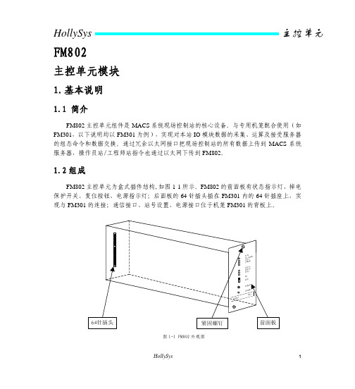
1.2组成FM802主控单元为盒式插件结构,如图1-1所示。
FM802的前面板有状态指示灯、掉电保护开关、复位按钮、电源指示灯;后面板的64针插头插在FM301内的64针插座上,实现与FM301的连接;通信接口、站号设置、电源接口位于机笼FM301的背板上。
图1-1 FM802外观图HollySys 1FM802 主控单元模块 2.原理说明FM802接口电路原理框图如图2-1所示。
DP主站接口采用数字信号处理技术(DSP)和高速通用异步收发器(UART)实现DP通讯,DSP与PC/104总线接口采用双口RAM。
静态数据存储器(SRAM)实现掉电保护和重要数据备份功能。
两个以太网接口SENT1、SENT2采用10Base-T(使用RJ45连接器)网络标准,实现与外部(服务器站/操作员站/工程师站)的数据交换,一个以太网接口RNET用于主/从主控单元间的数据备份。
站地址(6位)由FM301背板上拨码开关设置。
FM802的输入电源为+24V,由调压模块转换成+5V,供内部芯片使用。
3.使用说明3.1前面板说明FM802主控单元的前面板外观如图3-1所示:2 HollySysFM802 主控单元模块图3-1主控单元的前面板图3.2状态指示灯说明模块上电后,其面板上的15个LED 状态指示灯显示当前的工作和通讯状态。
具体状态及含义如表1所示。
表1 状态指示灯状态定义亮 主控单元处于运算状态 RUN (绿)灭 主控单元处于停止状态 亮 主控单元为从机(双机) 灭 主控单元为主机(双机)STDBY (黄)闪主控单元为单机或双机系统中一个主控单元故障亮 DP 控制网A 正常工作灭 DP 控制网A 无数据流 CNETA (黄)闪 DP 控制网A 有断线 亮 DP 控制网A 正常工作灭 DP 控制网A 无数据流 CNETB (黄) 闪 DP 控制网A 有断线 S1_LAN (黄)亮系统网1上电正常HollySys 3FM802 主控单元模块闪系统网1有发送数据(工作正常)灭系统网1坏或模块失电亮系统网1网线连接正常S1_LINK(绿)灭系统网1网线断或未连接亮系统网2上电正常S2_LAN(黄)闪系统网2有发送数据(工作正常)灭系统网2坏或模块失电亮系统网2网线连接正常S2_LINK(绿)灭系统网2网线断或未连接亮备份网上电正常R_LAN(黄)闪备份网有发送数据(工作正常)灭备份网坏或模块失电亮备份网网线连接正常RT_LINK(绿)灭备份网网线断或未连接(单机)注:1 ERROR(红灯)、SENT1(黄灯)、SENT2(黄灯)、CNET(黄灯)、RNET(黄灯)针对不同的软件版本,其状态表示的含义不同。
802仪表
TW-C802仪表说明一 : 系统性能1:专用工业级控制微处理器,系统稳定,运行可靠。
2:E2ROM保护数据,数据不丢失。
3:低温漂,低噪声放大器,真正做到了仪表低漂移。
4:多路模拟量输入,多路模拟量输出。
模拟量输入:16位 .模拟量输出12位。
5:仪表具有自动校零功能。
6:环境温度: -30℃~45℃。
7:仪表计量精度:优于0.05‰8:液晶2*10汉字显示,20个工作按键,单发光管状态显示。
9:可控制多种秤体:恒速秤调速秤静态秤等。
A:开光量输入输出全光电隔离。
B:脉冲速度输入.光电隔离。
C:外部开光量启动停机。
D:0~10MA 或0~20MA 或4~20MA 外部流量设定输入(全隔离)E:0~10MA 或0~20MA 或4~20MA 当前流量输出(全隔离)。
F:传感器供电6V,电流150MA。
G:开光量输出:报警指示运行指示上电备妥。
H:仪表具有2级放大功能:一级硬件放大二级程控放大。
注意:1:仪表电源进线必须接好,接线螺丝压紧。
不允许出现接触不好,受潮生锈现象。
2:仪表控制柜仪表接地线必须单独接大地。
3:传感器屏蔽线必须单独接大地。
仪表控制柜接地传感器屏蔽线接地和强电电器接地,不能共用一个接地。
4:变频器变频器控制柜必须接大地。
5:变频器控制的电机必须接大地。
6:供电电源严禁与大功率或启动频繁的电器共用。
安装前必须仔细阅读本说明书,清楚各个细节,保证安装质量。
二:技术指标1:供电电源:AC220V±10% 20W 50HZ/60HZ。
2:模拟量输入0-1.25V 对应数字0-60000。
3:传感器供电6V ,放大器最大输入12.5MV。
4:模拟量控制输出(隔离):0-5V。
B:仪表尺寸:长*宽*高=285*85 *265 MM。
功能代码一览表:5:外部流量设定输入:4~20MA 0~20MA 0~10MA (隔离)。
6:当前流量输出 :4~20MA 0~20MA 0~10MA (隔离)。
802说明书

Analog Way (Bei Jing)
效果: 切换,画中画,淡入淡出,字幕,擦除
- SDTV(15KHz):SDI,YUV, 分量信号,S.VIDEO, 复合视频 NTSC/PAL
用户控制: 前面板配置齐全 - 4 行显示 LCD,直观的菜单显示,可以完成输入输出设置和图象控制。 - 高质量按钮: - 输入选择 - 用户可控排序转换效果 - 图象切换 - 冻结图象画面 - LOGO,图象&画中画水平&垂直位置调整 可通过远程控制台或提供的软件进行完全控制。
Analog Way (Bei Jing)
技术参数:
8 路通用视频输入: ·复合视频
NTSC=15.735KHz/60Hz PAL/SECAM=15.625KHz/50Hz ·S.VIDEO(Y/C) ·分量视频(YUV) 525L/625L ·RGB/S(TTL 或 0.3V Analog) RGsB(SOG:0.3V Analog ) ·计算机信号(RGBHV,RGB/S,RGsB):PC,MAC,工作站。 自动同步锁定及标定分辨率从 640*480 到 1600*1280(最高到 110Hz 的刷新率)。 ·HDTV:分量(HD YUV 3 级同步) 1080i/60Hz,720p/60Hz,480p/60Hz ·选配: - SDI-4:2:2(10 bit) - DVI 最高至 UXGA
特点:
·主输出&预览输出的混合模式 ·内置矩阵模式:8 路输入到 2 路定标输出 ·8 路通用输入(可高至 UXGA,Video,HDTV)
802说明书

目录前言 (1)产品概述 (2)产品性能 (2)部件介绍 (3)安装说明 (4)显示面板说明 (5)参数设置 (5)操作简图 (9)物件探测调节 (10)装箱清单 (10)技术参数 (11)注意事项 (12)常见故障及解决办法 (12)干扰说明 (13)前言首先,感谢你购买本公司的金属探测门!!!本说明书对本产品进行了充分的描述与说明,在使用本产品前,您可以花一小段时间来阅读本说明书,这样您可以更了解本产品的性能,更好的去操作,同时您也能看到本产品更好的性能。
金属探测门可以应用于机场,监狱,考场,工厂等场所,对通过的人体进行准确检测身上是否携带金属物品。
本说明书对通过式金属探测门的安装与使用进行了详细的说明。
适用对象为使用产品客户,了解产品潜在客户等群体。
注意:本公司有权对本说明书及产品进行变更,如有变更,恕不另行通知。
本说明书编制过程中力求内容的准确和完善,但不保证本说明书没有任何错误或漏失,若有错误与缺失之处,欢迎来电赐教,我们将把您的意见作为修正参考意见之一。
- 1 -- 2 -我公司生产的802标准版通过式金属探测门采用了国际先进技术,专门用于对人身上隐藏的金属及合金物品的探测防范,它安全性高,适用性强,灵敏度高,探测范围广,抗外界干扰能力强,能够全天智能工作,并可以声光同时报警,在质量,效果,技术上均达到了世界领先水平,它可以调节灵敏度,最高精确探测可以小到曲形别针大小的金属物,并可以区分人体隐藏的具体位置,用户还可以根据金属的大小,体积,重量等进行灵敏度的设置,以排除钥匙,首饰,皮带金属扣而产生的误报警,而且本产品还可以防止贵重物品的流失,如海关,生产重金属工厂,私人毫宅等地方,都可以购买本产品作为一道安全防护。
因此安装本公司生产的通过式金属探测门是你英明的选择!◆ 六个探测区域:6个相互重叠的探测区域划分,准确判断金属物品的位置。
◆ 报警区域指示:在门的两边或主机箱有与人体等高的报警部位指示灯,配和声音,一目了然,大大提高工作效率。
MW801、MW802 Smart Combined Meter 用户手册说明书

USER MANUALPORTABLE pH/EC/TDS METER MODEL: MW801, MW802Smart Combined MeterWARRANTY:This instrument is warranted from all defects in materials and manufacturing for a period of two years from the date of purchase.The probe is warranted for a period of six months .If during this period the repair or replacement of parts is required, where the damage is not due to negligence or erroneous operation by the user, please return the parts to either distributor or our office and the repair will be effected free of change.Note :We reserve the right to modify the design,construction and appearance of our productswithout advance notice.PRELIMINARY EXAMINATIONRemove the instrument from the packing material and examine it carefully to make sure that no damage has occurred during shipment. If noticeable damage is found, notify your Dealer.Each meter is supplied complete with:•MA850DIN preamplified non refillable double junction combination pH electrode with built in EC/TDS probe and temperature sensor;1m (3.3') cable.•pH7.01, 1413 µS/cm & 1382 ppm (for MW801)or 1500 ppm (for MW802) solutions, 20 mL each.•Instruction Manual.• 1 x 9V battery.OPERATIONSlide the battery compartment cover located on the back of the meter off, and install the battery into the battery clip connector while observing polarity.Connect the probe to the meter securely by aligning the pins with the socket and pushing the plug in.Always remove the electrode protective cap before use.Make sure that the meter has been calibrated before taking any measurements (see calibration procedure).Turn the instrument on by pressing the ON/OFF key.pH MEASUREMENTSIf the electrode has been left dry, soak the tip in a pH7 (M10007) buffer solution for a few minutes to reactivate it.Submerge the tip of the electrode into the sample to be measured, select the pH mode and allow the reading to stabilize before taking measurements.EC/TDS MEASUREMENTSImmerse the tip of the electrode into the sample to be tested.Select the measurement range (EC or TDS)and wait for the temperature sensor to reach thermal equilibrium with the samples before taking measurements.CALIBRATION PROCEDURE:Remove the protective cap from the electrode.Switch the meter on.Select the range pressing the appropriate key for pH, EC or TDS.pH Calibration A) PREPARATIONSingle point manual calibration. Choose buffer.If you are going to measure samples near pH 7use pH 7.01 buffer solution (M10007B ) for calibration;use pH 4.01 buffer solution (M10004B ) for acidic measurements, or pH 10.01(M10010B ) for alkaline measurements.B) PROCEDURERinse the tip of the electrode and immerse it in the calibration solution. Wait a couple of minutes for the reading to stabilize.Measure the temperature of the buffer solution with a thermometer.Adjust the calibration knob until the LCD shows the pH value of the buffer at the measured temperature (see pH versus temperature chart).The calibration is now complete and the meter is ready for use.EC/TDS calibration:A)PREPARATIONSingle point EC calibration.Choose appropriate standard:Model MW801: use 1382 ppm(M10032B ) for TDS or 1.413 μS/cm (M10031B )for EC calibration.Model MW802: use 1500 ppm (M10442B ) for TDS or 1.413 mS/cm (M10031B ) for EC calibration.B)PROCEDUREImmerse the tip of the electrode in the standard solution.Wait for the reading to stabilize, and thermal equilibrium be reached.Turn the EC/TDS calibration knob until the display shows the EC or TDS reading at 25°C.The calibration is now complete and the meter is ready for use.The instrument should be re-calibrated at least once a month, or when the probe or battery is replaced.Note :The conversion between EC and TDS ismade by a built-in circuit. If calibration is made in EC range, TDS range is automatically calibrated (or vice versa).BATTERY REPLACEMENT:The meters are powered by a 9V battery that is in a compartment located in the rear of the instrument.When the battery becomes weak, the instrument automatically switches off.Replacement must only take place in a non-hazardous area using an alkaline 9V battery. Slide off the battery compartment cover and replace the old battery with a new one. Make sure that the battery contacts are fully engaged in the connector. Seat the battery in is compartment and replace the cover.pH VERSUS TEMPERATURE CHARTOPTIONAL ACCESSORIESM10007B pH7.01 buffer solution,25x20 mL sachetM10004B pH4.01 buffer solution,25x20 mL sachetM10010B pH10.01 buffer solution,25x20 mL sachetM10031B 1413 μS/cm calibration solution, 25x20 mL sachet M10032B 1382 ppm calibration solution, 25x20 mL sachet M10442B1500 ppm calibration solution, 25x20 mL sachet P M E T S E U L A V H p C °F °4009A M 7009A M 0109A M 02310.431.723.0151400.401.742.01010500.470.781.01519500.440.721.01028600.430.760.01527710.410.710.01036820.400.769.9535930.499.629.90440140.489.658.95431150.489.658.90522160.489.628.95513170.489.697.90604190.489.677.95694111.499.667.90785121.499.657.9SPECIFICATIONS:MW801MW802RANGE0.0 to 14.0 pH 0.00 to 14.00 pH 0 to 1990 ppm 0 to 4000 ppm 0 to 1990 μS/cm0.00 to 6.00 mS/cmRESOLUTION0.1 pH 0.10 pH 10 ppm 10 ppm 10 μS/cm 0.01 mS/cmACCURACY ± 0.2 pH ±0.20 pH (@ 20ºC)±2% Full scale ±2% Full scaleCALIBRATION M10007B (pH 7.01)SOLUTIONSM10031B (1.413 mS/cm)M10032B (1382ppm)M10442B (1500ppm)CONVERSION 0.50.68FACTOR CALIBRATIONManual, at 1 pointTEMPERATURE COMPENSATIONAutomatic from 0 to 50ºCPROBE MA850DIN combination pH/EC/TDS probeENVIRONMENT0 to 50ºC, 95%RH maxBATTERY LIFE /TYPE1x9V alkalineapprox. 150 hours of use DIMENSIONS 143 x 80 x 32 mm WEIGHT220 g (with battery)。
PMAC802_MODBUS通讯协议V1.0

PMAC®802低压电动机保护控制器MODBUS串行通信协议V1.0ZHUHAI PILOT TECHNOLOGY Co.,Ltd珠海派诺科技股份有限公司目录第一章简介 (3)1.1 串行通讯协议的目的 (3)1.2 MODBUS通讯协议的版本 (3)第二章PMAC®802-MODBUS 串行通信协议详细说明 (3)2.1 PMAC®802-MODBUS协议基本规则 (3)2.2 传送模式 (3)2.3 MODBUS包裹结构描述 (3)2.4 网络时间考虑 (4)2.5 异常响应 (4)2.6 广播命令 (5)第三章通讯包裹 (5)3.1 读寄存器(功能码03) (5)3.2 写寄存器(功能码16) (5)第四章计算CRC-16 (6)第五章PMAC®802寄存器说明 (7)5.1实时数据寄存器 (7)5.2 设备参数寄存器 (12)5.3 保护整定参数寄存器 (14)5.4 控制寄存器 (17)5.5 故障记录寄存器 (17)5.6 时钟寄存器 (18)5.7 欠压重启动功能寄存器 (18)第一章简介通信协议详细地描述了PMAC®802在MODBUS通讯模式下的输入和输出命令、信息和资料,以便第三方使用和开发。
1.1 串行通讯协议的目的通信协议的作用使信息和资料在上位机(主站)和PMAC®802之间有效地传递,它包括:1)允许主站访问和设定所接PMAC®802的全部设置参数;2)允许访问PMAC®802的所有测量资料和事件纪录。
1.2 MODBUS通讯协议的版本该通讯协议适用于本公司已经出厂的所有各种版本的PMAC®802仪表,对于日后的系列若有改动会加以特别说明。
第二章PMAC®802-MODBUS 串行通信协议详细说明2.1 PMAC®802-MODBUS协议基本规则以下规则确定在RS485(或者RS232C)回路控制器和其它RS485串行通信回路中设备的通信规则:1)所有RS485回路通信应遵照主/从方式。
PMAC基础调试资料
PMAC总结一PMAC 简介 (2)1-1 PMAC 含义 (2)1-2 PMAC 特点 (3)1-3 PMAC 分类 (3)1-4 PMAC 常用附件 (3)二PMAC 硬件接线 (4)2-1 PMAC跳线的设置 (4)2-2 PMAC转接板的选用 (4)2-3 PMAC 接口 (4)2-3-1 PMAC I型卡的接口 (4)2-3-2 PMAC 2型卡的接口 (5)2-4 PMAC卡的示意图 (6)2-4-1 PMAC一型卡的接线示意图 (6)2-4-2 PMAC2A-PC104 卡的接线示意图 (6)2-5 PMAC 的使能接线示意图 (8)2-6 PMACI 型卡J5(JOPT)接线示意图 (9)三PMAC 相关软件 (10)3-1 执行软件 (10)3-2 开发软件 (10)四PMAC 基本参数 (10)4-1 PMAC I变量 (10)4-1-1 PMAC一型卡的I 变量参数设置 (11)4-1-2 PMAC二型卡的I 变量参数设置 (11)4-1-3 PMAC2A-PC/104型卡I 变量参数设置 (12)4-2 PMAC P 变量 (13)4-3 PMAC Q 变量 (13)4-4 PMAC M 变量 (13)五PMAC电机PID调整 (13)5-1 PID调整的前提 (13)5-2 与PID 调整有关的I 变量 (14)六PMAC运动指令 (14)6- 1开环指令 (14)6-2 闭环指令 (14)6-3 回零指令 (14)七注意事项 (15)一PMAC 简介1-1 PMAC 含义PMAC是program multiple axis controller 可编程的多轴运动控制卡。
1-2 PMAC 特点PMAC卡是美国deltatau公司的产品,是集运动轴控制,和PLC控制以及数据采集的多功能的运动控制产品.1-3 PMAC 分类1)PMAC 按控制电机的控制信号来分,可分为一型卡和二型卡 ,一型卡输出+-10V模拟量,主要用于速度方式控制伺服电机,二型卡输出 PWM 数字信号,可直接变为 PULSE+DIR 信号,来控制步进电机和位置控制方式的伺服电机2)PMAC卡按照控制轴数来分如下表格当然除了板卡的形式以外,PMAC还有集成的系统产品,有UMAC QMAC ADVANTAGE NC400 NC800 等1-4 PMAC 常用附件二PMAC 硬件接线2-1 PMAC跳线的设置在PMAC 接线之前,先进行跳线的设置.1)PMAC一型卡的跳线设置E85 E87 E88 :设置PMAC卡模拟量电源,缺省设置为都设为OFF状态,表示PMAC卡的模拟量电源+-12~+-15V是通过外部供给;而如果都设为ON,表示模拟量+-12~+-15电源是从PC机总线得到;E89 E90:设置+-LIMn 和FLAG 的电源供给,这两个跳线需要随着E85 E88的设置变化而变化,E90的跳线在1`2 的时候表示从J11供电,在2`3 的时候从总线供电;E51: PMAC卡从新初始化的设置,此跳线在PMAC卡正常工作时,应为OFF, 卡由于故障或其他原因需要初始化时,才需将此跳线设为ON;E3—E6:伺服时钟频率与I10变量有关,缺省为E5 E6为ON;E29—E33:相时钟频率,缺省为9.04KHZ,E31设为ON;E34—E38 :编码器采样时钟频率,缺省为:9.8304MHZ E34设为ON;E17A-E17D: 1-4电机的伺服使能的极性控制;E24—E27: 1-4 编码器的输入形式控制,是单端/差分线驱动输入,1-2 ON集电极开路, 2-3 ON;E40—E43 :PMAC卡号的设置,缺省为E40—E43都设为ON,相当于是 @0号卡;E44—E47 :设置串口通讯的波特率。
PMAC800说明书

PMAC800 低压电动机保护控制器
产品说明书 V2.0
(本公司保留修改说明书而不另行通知的权利)
安全注意事项
安全注意事项
危险和警告
本设备只能由专业人士进行安装。 对于因不遵守本说明书的说明而引起的故障,厂家将不承担任何责任。
注意事项提示
在拆容。对于注明 为『注』的内容请额外予以关注。
5.1 电动机运行状态的划分.........................................................................................................................................9 5.2 启停操作 ................................................................................................................................................................9 5.3 保护/控制 ...............................................................................................................................................................9 5.4 故障信息输出 ........................................................................................................................................................9 5.5 失电自诊断 ..........................................................................................................................................................10 5.6 复位方式 ..............................................................................................................................................................10 5.7 操作权限 ..............................................................................................................................................................10
PMAC卡简介
1.PMAC卡-简介和预备知识PMAC卡是功能非常强大的运动控制卡,但是网上PMAC的教程很少,仅有的几个教程还是官网培训教程,罗列概念和记流水账,最不喜欢这样的教程。
自己学习PMAC卡的时候走了许多弯路,刚好找完工作就写一下PMAC的相关教程,看完整个系列的教程,相信对于PMAC的使用是没有问题的,主要分为以下几个模块:1.简介和预备知识2.PMAC硬件3.PMAC下位机编程4.PMAC上位机编程PMAC简介PMAC基本上算是自动控制行业中功能最强大的运动控制卡了,虽然价格不菲,但是使用及其方便,功能也极其强大,怎么强大自己去搜啦,这是官网链接。
PMAC是一系列控制卡的简称,常用的有PMAC1、PMAC2、Turbo PMAC1、 Turbo PMAC2、UMAC、Clipper等,基本功能和使用方法是一样的,这里我使用的是Turbo PMAC1控制卡。
在国内PMAC有多家代理,笔者固定联系的是苏州均信,维修的话有北京泰道公司,北京泰道公司的官方QQ群号为190220668 ,在群里面可以提问,有各路大神和官方人员解答疑问,群共享里面也有许多资料供学习。
运动控制基础“工欲善其事,必先利其器”,在本文中还是先说一下运动控制相关理论,这里只是一些基本概念,深入了解还是要自行查看相关资料。
定义:在复杂条件下将预定的控制方案、规划指令转变成期望的机械运动,实现机械运动精确的位置控制、速度控制、加速度(转矩)的控制。
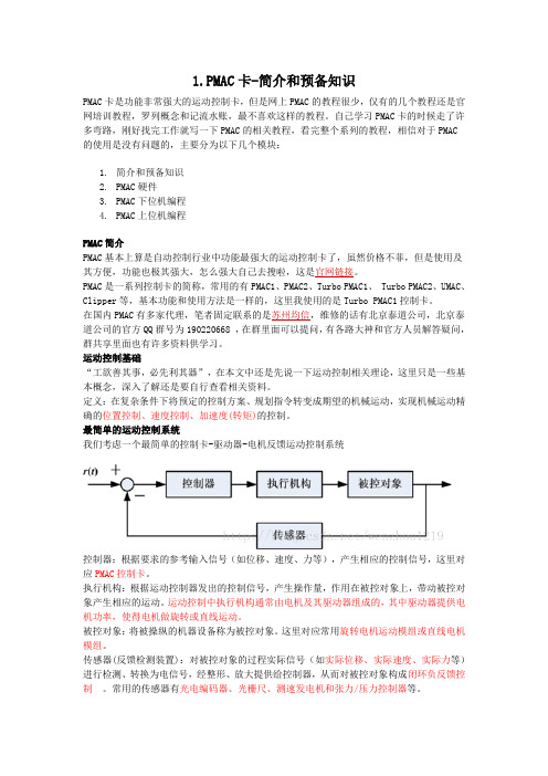
最简单的运动控制系统我们考虑一个最简单的控制卡-驱动器-电机反馈运动控制系统控制器:根据要求的参考输入信号(如位移、速度、力等),产生相应的控制信号,这里对应PMAC控制卡。
执行机构:根据运动控制器发出的控制信号,产生操作量,作用在被控对象上,带动被控对象产生相应的运动。
运动控制中执行机构通常由电机及其驱动器组成的,其中驱动器提供电机功率,使得电机做旋转或直线运动。
被控对象:将被操纵的机器设备称为被控对象。
康全902电力猫快速设置说明书

康全902电力猫快速设置说明书一、概述Comtrend PowerGrid 902电力猫必须成对使用,或者一对多使用。
至少有一个主端(AP端)和一个从端(EP端),从端也可以是多个康全。
设置的基本要求分以下三个步骤:(1)设置第一个主端;(2)恢复从端为出厂模式;(3)从端与主端对码。
也可以继续按(2)(3)步骤设置多个从端。
二、具体设置步骤1、先设置一个主端,也称为AP端,这个概念与无线局域网类似。
AP的设置方法:选定一个机器作为AP,并记录做好标记,按一下AP面板上的CONFIG/RESET键,第一个绿灯(AP/STBY)开始闪动,此时耐心等待AP灯闪30秒后停止闪动,即设置为AP模式。
2、恢复从端为出厂模式从端也称为客户端(EP),要使EP与AP匹配,必须先清除原来的设置,进入出厂状态。
具体方法是:先按EP面板上的CONFIG/RESET键十几秒,等待3个指示灯(LED)全部变绿灯后,第三个(STATUS)灯再次变红后,就恢复到出厂状态了,可以进行下一步的对码匹配了。
3、从端与主端对码对码的过程是:先在AP上按一下CONFIG/RESET键,等hxx886(2014-08-07 22:49:08):它开始闪以后,再迅速到EP上按CONFIG/RESET键,EP的第一灯(AP/STBY)会闪三下,然后第三灯(STATUS)会变成绿色,这时表示已经互相设置好了。
4、设置其他的从端(EP)按照2和3步骤依次设置其余的EP。
全部设好后,就可以分开使用了。
三、注意事项1、正常AP工作时是第一灯(主模式)和第二灯(以太网指示)常绿,第三灯(工作状态)红闪。
2、AP端的网口一般接互联网那边(通常是路由器),EP端接设备(通常是电脑、网络电视等)。
hxx886(2014-08-07 22:49:07):康全902电力猫快速设置说明书一、概述Comtrend PowerGrid 902电力猫必须成对使用,或者一对多使用。
CSA802-P048T02 电流传感器用户手册说明书

CSA802-P048T02电流传感器使用说明书V1.04本手册为湖南银河电气有限公司产品CSA802-P048T02电流传感器用户手册,本手册为用户提供安装调试、操作使用及日常维护的有关注意事项,在安装、使用前请仔细阅读。
本手册随产品一起提供,请妥善保管、以备查阅和维护使用。
声明我们非常认真的整理此手册,但我们对本手册的内容不保证完全正确。
因为我们的产品一直在持续的改良及更新,故我方保留随时修改本手册的内容而不另行通知的权利。
同时我们对不正确使用本手册所包含内容而导致的直接、间接、有意、无意的损坏及隐患概不负责。
安全操作知识◆产品使用前,请您务必仔细阅读用户手册。
◆需对产品进行搬动时,请您务必先断电并将与之相连的所有连接线缆等拔掉。
◆如果发现机壳、稳固件、电源线、连接线缆,或相连的设备有任何损坏,请您立即将装置与电源断开。
◆如果对设备的安全运行存在疑虑,应立即关闭设备和相应附件,并在最快时间内与本公司技术支持部门取得联系,沟通解决。
!安全警示电流传感器不允许开路使用,即母线有电流或传感器已上电的状态下,都不允许断开输出端;仅母线无电流且传感器未上电的状态下,才可以断开传感器的电流输出端或主机与探头的连接,否则有感应高压,发生电击的危险!1. 产品概述CSA802-P048T02是一种能在原边、副边完全隔离条件下测量直流、交流、脉冲以及各种不规则波形的电流传感器,它主要用于要求准确度高的计量检定和计量校准领域,以及要求高灵敏度、高稳定性和高可靠性的电能质量分析、功率分析仪、医疗、航空航天、导弹、舰艇等领域。
2. 技术特点●极高的准确度●极好的线性度●极高的稳定性●极高的灵敏度●极高的分辨率●极低的温度漂移●极低的失调电流●极低的插入损耗●抗干扰能力强●响应速度快●极低的噪声●极小的角差●宽频带●模拟量输出3. 应用场合●计量检定与校准●实验室电流测量●仪器仪表(如功率分析仪)●医疗设备(如核磁共振MRI)●电池组检测●电力控制●电源●舰船●新能源●轨道交通●航空航天●工业测量4. 电气性能项目符号测试条件数值单位最小标称最大原边额定电流 I PN-- -- ±8000 -- Adc 测量范围 I PM1分钟/小时 -- -- ±9600 Adc 工作电压 V c全范围 -- ±70 -- Vdc 电源消耗 I PM范围内 -- 300 -- W 电流变比 K N输入:输出 8000:1 -- 额定输出电流 I SN原边额定电流 --±1-- A 测量电阻 R M0 -- 1 Ω5. 精度-动态参数项目符号测试条件数值单位最小标称最大精度 X e输入直流,25±10℃ -- -- 10 ppm比差误差 X Ge输入交流50Hz/60Hz,25±10℃ -- -- 100 ppm角度误差 X Pe-- -- 0.01 crad 线性度 εL-- -- -- 2 ppm 温度漂移系数 TCI OUT-- -- -- 0.1 ppm/K 时间漂移系数 TT -- -- -- 0.2 ppm/month 供电抗干扰 TV -- -- -- 1 ppm/V 零点失调电流 I o25±10℃ -- -- 2 ppm 零点失调电流 I oT全工作温度范围内 -- -- ±10 ppm 纹波电流 I n DC-10Hz -- -- 0.5 ppm 动态响应时间 t r-- -- -- 1 us 电流跟随速度 di/d-- 200 -- -- A/us 频带宽度(-3dB) F -- 0 -- 10 kHz 6. 一般特性项目符号测试条件数值单位最小标称最大工作温度范围 T A-- -10 -- +70 ℃ 存储温度范围 T S-- -25 -- +85 ℃ 7. 安全特性项目符号测试条件数值单位最小标称最大耐受电压原、副边之间副边与外壳之间V d50Hz,1min 5 kV瞬态隔离耐压 原、副边之间 V w50us 7.5 kV 相比漏电起痕指数 CTI IEC-60112 1 kV8. 外形尺寸及端口定义8.1. 电流传感器外形及尺寸图(单位:mm)图1 主机外形尺寸外形图说明:●公差:外形尺寸、安装定位尺寸公差按照GB/T1804-2000 C级标准执行。
- 1、下载文档前请自行甄别文档内容的完整性,平台不提供额外的编辑、内容补充、找答案等附加服务。
- 2、"仅部分预览"的文档,不可在线预览部分如存在完整性等问题,可反馈申请退款(可完整预览的文档不适用该条件!)。
- 3、如文档侵犯您的权益,请联系客服反馈,我们会尽快为您处理(人工客服工作时间:9:00-18:30)。
产品说明书V1.1
珠海派诺电子有限公司
ZHUHAI PILOT ELECTRONICS CO ., LTD
3
5
11 13
16 22 27
35
38 39 43 44
产品介绍
1
产品介绍
2
技术参数
3
技术参数
4
结构尺寸和安装方式
5
结构尺寸和安装方式
6
结构尺寸和安装方式
7
结构尺寸和安装方式
8
结构尺寸和安装方式
9
结构尺寸和安装方式
10
控制器功能配置
11
控制器功能配置
12
电动机控制及其他功能
13
电动机控制及其他功能
14
电动机控制及其他功能
15
显示模块
16
显示模块
17
显示模块
18
显示模块
19
显示模块
20
显示模块
21
各个模块端子及功能说明
34
系统参数设置
35
系统参数设置
36
系统参数设置
37
开关量输入和继电器输出配置
38
典型运行模式接线
39
典型运行模式接线
40
典型运行模式接线
41
典型运行模式接线
42
基本设置和常见问题
43
订货信息
44
订货信息
45
22
各个模块端子及功能说明
23
各个模块端子及功能说明
24
各个模块端子及功能说明
25
各个模块端子及功能特性及参数整定
28
保护特性及参数整定
29
保护特性及参数整定
30
保护特性及参数整定
31
保护特性及参数整定
32
保护特性及参数整定
33
保护特性及参数整定
