【NEMA尺寸】
防水套管尺寸标准

防水套管尺寸标准
防水套管的尺寸标准可以根据不同的国家和地区而有所不同。
以下是一些常见的防水套管尺寸标准:
1. 美国标准:根据国家电气制造商协会(NEMA)标准,防水套管常见尺寸为1/2英寸(1
2.7毫米)、3/4英寸(19.05毫米)、1英寸(25.4毫米)、1-1/4英寸(31.75毫米)、1-1/2英寸(38.1毫米)、2英寸(50.8毫米)、2-1/2英寸(6
3.5毫米)和3英寸(76.2毫米)。
2. 欧洲标准:根据欧洲电工制造商联合会(CECAPI)标准,防水套管常见尺寸为16毫米、20毫米、25毫米、32毫米、40毫米和50毫米。
3. 中国标准:根据中国国家标准(GB/T)标准,防水套管常见尺寸为16毫米、20毫米、25毫米、32毫米、40毫米、50毫米、63毫米、75毫米、90毫米、110毫米、130毫米、150毫米、175毫米、200毫米、225毫米、250毫米、300毫米和400毫米。
需要注意的是,以上仅为常见的防水套管尺寸标准,实际应用中可能会根据具体需求而有所差异。
为确保安装的质量和符合相关标准和规范,建议在选择和安装防水套管时参考当地的有效标准。
nema插头标准

nema插头标准
NEMA插头标准
NEMA插头标准是美国国家电器制造商协会(NEMA)制定的一种插头标准。
该标准规定了插头的尺寸、形状、电气参数等方面的要求,以确保插头的安全性和互换性。
NEMA插头标准分为多个系列,每个系列都有不同的编号和用途。
其中最常见的是NEMA 1-15系列和NEMA 5-15系列。
NEMA 1-15系列插头是一种两脚插头,通常用于低功率电器,如电灯、电扇等。
该插头的尺寸为1.5英寸×0.5英寸,电压为125伏特,电流为15安培。
该插头的两个脚是平的,没有极性之分,因此可以随意插入插座。
NEMA 5-15系列插头是一种三脚插头,通常用于高功率电器,如电视、电脑等。
该插头的尺寸为1.75英寸×0.75英寸,电压为125伏特,电流为15安培。
该插头的三个脚分别为两个平脚和一个圆脚,其中一个平脚为接地脚,用于保证电器的安全性。
除了以上两种常见的插头,NEMA还制定了其他系列的插头标准,如NEMA 6-15系列、NEMA 10-30系列等。
这些插头的尺寸、形状、电气参数等方面的要求都有所不同,适用于不同的电器和用途。
总的来说,NEMA插头标准是一种非常重要的标准,它保证了插头
的安全性和互换性,使得不同品牌、不同型号的电器可以在同一插座上使用。
因此,在购买电器时,我们应该注意选择符合NEMA插头标准的电器,以确保使用的安全和方便。
57步进电机参数

57步进电机参数步进电机是一种常用于控制精确位置和运动的驱动器。
57步进电机,也被称为NEMA 23步进电机,是一种常见的步进电机规格。
在本文档中,我们将详细介绍57步进电机的参数。
1. 电机尺寸:57步进电机的名称“57”代表了它的尺寸,也被称为NEMA尺寸。
57步进电机的外形尺寸为57mm x 57mm(2.24英寸 x 2.24英寸)。
这个尺寸使得57步进电机适合于许多各种应用,包括3D打印机、机械臂、自动化设备等。
2. 步距角:57步进电机的步距角是指电机每一步转动的角度。
常见的57步进电机的步距角为1.8度。
这意味着电机每转动一次,需要分为200个步进,每步进0.9度。
步距角决定了电机的分辨率和精度,它是控制步进电机精确位置的关键参数。
3. 相数和相电流:57步进电机通常有两相或四相。
相数指的是电机中的线圈数量。
两相步进电机有两个线圈,四相步进电机有四个线圈。
相电流是电机中每一个相的电流。
较高的相电流可以提供更强的转矩和功率输出,但也会产生更多的热量。
4. 额定电压和额定电流:57步进电机的额定电压和额定电流是指电机的正常工作条件下的电压和电流。
额定电压通常为24V或48V,而额定电流则根据应用需求来选择。
在设计步进电机驱动电路时,必须考虑电机的额定电压和额定电流,以确保电机能够正常工作。
5. 静态转矩和动态转矩:静态转矩是电机在停止转动时产生的最大输出转矩。
动态转矩是电机在运动时产生的最大输出转矩。
57步进电机的静态转矩和动态转矩取决于电机的驱动方式和电流。
较高的电流可以提供更大的转矩输出,但同时也会增加电机的发热。
6. 转速范围:57步进电机的最大转速取决于电机的驱动方式和额定电压。
通常,在实际应用中,电机的转速会相对较低,以确保精确的位置控制和运动平滑。
7. 绝缘等级:57步进电机的绝缘等级指的是电机的绝缘性能。
通常,绝缘等级根据应用需求来选择,以确保电机的安全使用。
8. 重量和负载能力:57步进电机的重量取决于其设计和构造。
nema法兰尺寸
NEMA法兰是一种广泛应用于电气设备中的连接器,其尺寸标准由美国国家NEMA法兰是一种广泛应用于电气设备中的连接器,其尺寸标准由美国国家电气制造商协会(National Electrical Manufacturers Association,简称NEMA)制定。
NEMA法兰的尺寸通常以数字表示,例如NEMA 1、NEMA 2、NEMA 4等。
NEMA法兰的尺寸主要是指其直径和螺孔的大小。
例如,NEMA 1法兰的直径为1英寸,螺孔大小为13/64英寸;NEMA 2法兰的直径为1.5英寸,螺孔大小为7/32英寸;NEMA 4法兰的直径为3英寸,螺孔大小为5/16英寸等。
这些尺寸标准的设定,使得不同规格的NEMA 法兰可以适配不同的电气设备。
在选择NEMA法兰时,需要根据设备的具体要求和安装环境来确定。
例如,如果设备的电源线需要通过管道进行布线,那么就需要选择适合管道内径的NEMA法兰。
同时,还需要考虑法兰的防护等级,以确保其在恶劣环境下的使用安全。
NEMA法兰的安装也相对简单,只需要将法兰与设备和电缆连接好,然后用螺栓固定即可。
但是,需要注意的是,安装过程中必须确保电缆的绝缘层不被破坏,否则可能会导致电气事故的发生。
总的来说,NEMA法兰是一种非常实用的电气连接器,其尺寸标准的设定使得它可以广泛应用于各种电气设备中。
只要正确选择和使用,就可以大大提高电气设备的安装效率和使用安全性。
美国插头标准尺寸
美国插头标准尺寸
美国家庭常用电器标准插头是125V15A(带地极),其标准外形尺寸一般按NEMA1-15标准,标准中定义台式插头外端形状等相关参数。
NEMA1-15定义的美国标准插头外接形状如下:插头长度19mm、宽度最大为20.5mm、插片中央距台座两端间距6.4mm。
插头外形基本符合对称三角形,插片有两相介质插孔,端部有两个平口。
NEMA1-15在安全性能上规定了极性,其中插片最内外表面绿色为绝缘性,最外表面黑色为接地极位置。
NEMA1-15美国家用标准插头的使用介于100至125伏之间,其用电容量最大为15安培。
使用前需要经过检测确认其安全性能、绝缘性能、导体间极性连接正确、极性标识明显,以及插头表面完整无损等情况,确保其安全可靠性。
要注意的是,买到的插头应按规范执行,若插头出现破损、漏电等情况,应及时更换正规插头,以保证用电安全。
此外,使用时应注意:不能加薄套装、在插头上悬挂金属物品,以及插头极性与插孔的极性对应,否则可能会出现很大的安全风险。
美国家庭常用电器标准插头是125V15A(带地极),是一种安全可靠的插头,其尺寸符合NEMA1-15标准,具有良好的安全性能。
但使用插头时,一定要遵守使用规范,以确保电器的安全性能,从而安全使用电器。
变频器尺寸
ACS355
-
01E
-
02A4
-
2
+
A123
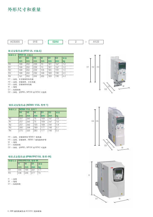
柜式安装传动 (IP20 UL 开放式)
外形尺寸 IP20 UL 开放式 H1 mm R0 R1 R2 R3 R4
H1 H2 H3 W D1 D2 = = = = = =
H2 mm 202 202 202 202 202
H3 mm 239 239 239 236 244
W mm 70 70 105 169 260
D1 mm 161 161 165 169 169
D2 mm 187 187 191 195 195
重量 kg 1.2 1.2 1.5 2.5 4.4
H1 H2 H3
169 169 169 169 181
高度,不含紧固件和夹板 高度,含紧固件,不含夹板 高度,含紧固件和夹板 宽度 标准深度 深度,含 MREL, MPOW 或 MTAC 可选件
D1 D2 W
壁挂式安装传动 (IP66/IP67/UL 类型 4X)
外形尺寸 IP66/IP67/UL 类型 4X H mm R1 R3 305 436 W mm 195 246 D1 mm 281 277 重量 kg 7.7 13
H H = 高度 W = 宽度 D1 = 标准深度
D1
W
8 ABB 通用机械传动 ACS355 | 技术样本
D1 D2
W
壁挂式安装传动 (NEMA 1/UL 类型 1)
外形尺寸 NEMA 1/UL 类型 1 H4 mm R0 R1 R2 R3 R4
H4 H5 W D1 D2 = = = = =
H5 mm 280 280 282 299 320
NEMA大小6非反转和反转接触器和启动器说明文件说明书
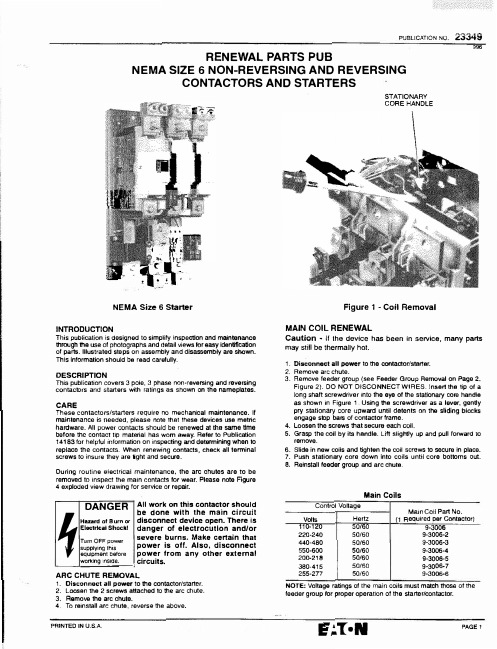
PUBLICATION NO.23349996RENEWAL PARTS PUBNEMA SIZE 6 NON-REVERSING AND REVERSINGCONTACTORS AND STARTERS.."__�---f . '. 1'' • "2k � l • . C,::«-•-tI· -�-.NEMA Size 6 StarterINTRODUCTIONThis publication is designed to simplify inspection and maintenance through the use of photographs and detail views for easy identification of parts. Illustrated ste ps on as sembly and disassembly are shown. This information should be read carefully.DESCRIPTIONThis publication covers 3 pole, 3 phase non-reversing and reversing contactors and starters with ratings as shown on the na meplates. CAREThese contactors/starters require no mechanical maintenance. If maintenance is needed, please note that these devices use metric hardware. All power co ntacts should be renewed at the same time before the contact tip material has wom away. Refer to Publication 14183 for helpful infor mation on inspecting and determining when to replace the contacts. When renewing contacts, check all terminal screws to insure they are tight and secure.During routine electrical maintenance, the arc chutes are to be removed to inspect the main contacts for wear. Please note Fi g ure 4 exploded view drawing for service or repair.DANGER�=�c�::hu��k�rTum OFF powersupplying this equipment before working inside.-�All work on this contactor should be done with the main circuit disconnect device open. There is danger of electrocution and/or severe burns. Make certain that power is off. Also, disconnect power from any other external circuits.ARC CHUTE REMOVAL1. Disconnect all power to the contactor/starter.2. Loosen the 2 screws attached to the arc chute.3.Remove the arc chute.4.To reinstall arc chute, reverse the above.STATIONARY CORE HANDLEFigure 1 -Coil RemovalMAIN COIL RENEWALCaution • If the device has been in service, many parts may still be thermally hot.1.Disconnect all power to the contactor/starter.2.Remove arc chute.3.Remove feeder group (see Feeder Group Removal on Page 2,Figure 2). DO NOT DISCONNECT WIRES. Insert the tip of a long shaft screwdriver into the eye of the stationary core handle as shown in Figure 1 Using the screwdriver as a lever, gently pry stationary core upward until detents on the sliding blocks engage stop bars of contactor frame.4.Loosen the screws that secure each coil.5. Grasp the coil by its handle. Lift slightly up and pull forward to remove.6.Slide in new coils and tighten the coil screws to secure in place.7.Push stationary core down into coils until core bottoms out.8. Reinstall feeder group and ar c chute.Main CoilsControl Voltage Main Coil Part No. Volts Hertz (1 Reauired oer Contactor)110-120220-240440-480550-600200-218380-415255-27750/60 50/60 50/60 50/60 50/60 50/60 50/609-3006 9-3006-2 9·3006-39-3006-4 9-3006-5 9-3006-79-3006-6NOTE: Voltage ratings of the main coils must match those of the feeder group for proper operation of the starter/contactor.PAINTED IN U.S.A.PAGE 123349 PUBLICATION NO.FEEDERGROUP�Figure 2 -Feeder GroupFEEDER GROUPIt supplies the main contactor coils with DC control voltage. Refer to the wiring diagram publication supplied with the contactor/starter when reconnecting wires to the new feeder group.FEEDER GROUP RENEWAL1.Disconnect all power to the contactor tstarter.2.Insert a screwdriver as shown in Figure 2 to pry the feeder group from the contactor frame.3.Disconnect the 6 wires going to the feeder gr oup.4.Connect the 6 wires to the new feeder group. Refer to the diagram supplied with the contactor/starter.5.Assemble new feeder group by inserting the 2 feeder group mounting tabs into the two slots in the contactor frame and pres s into the contactor frame.Feeder Group RenewalControl Voltage Feeder Group VoltsHertzIGomolete)110-120 50/60 9-3007220-24050/60 9-3007-2440-48050/60 9-3007-3550-60050/60 9-3007-420850/60 9-3007-5380-41550/60 9-3007-748-5250/608-3007-6NOTE: Voltage ratings of the main coils must match those of the feeder group for proper operation of the st a rter/contact o r. MAIN CONTACT RENEWALCaution • If the device has been in service. many parts may still be thermally hot.1.Disconnect all power to the contactor/starter.2.Remove arc chute.3.Press down on the movable contact assembly until the locking pins become loose. Remove locking pins by sliding them to the right or left. See Figure 3.4.Release pressure on the movable contact assembl y and remove.5.Remove stationary contacts by removing the allen e a 6mm alien wrench.6.Install new stationary contacts and screws.7.Assemble contact, springs, and spring retainers. Press down on the movable contact assembly and install the locking pins.8.Install arc chute.MOVABLE CONTACT........ASSEMBLYFigure 3 -Main Contact RenewalRENEWAL OF CURRENT TRANSFORMER 1.Disconnect all power to the starter.2.Remove the 2 screws holding the fuse block to the mounting plate and set fuse block aside.3.Remove green and black wires from the line side of the overload relay.4.Remove current transformer secondary wires fro m overload relay.5.Remove 4 screws holding overload relay and mounting plate to current transformer and set aside.6.Remove load side p ower lugs.7.Remove cur rent tran sformer mou nting scr ews.8.Remove current transformer by sliding down to clear base .9.Reinstall new current transformer by reversing the above.Make sure the transformer polarity is correct. Refer to wiring diagram supplied wijh starter.RENEWAL OF BIMETAL OVERLOAD RELAYThis bimetal, ambient compensated overload relay is adjustable within the FLA range of the heater pack. Each heater pack is marked with its range of FLA ratings. Select heater packs (3 required) according to the motor FLA rating and install in overload relay. Rotate FLA adjustment dial to a position corresponding to the motor FLA Consult overload relay publication supplied with the starter for proper setting and selection. The overload relay is factory set for manual reset operation. If automatic reset is required, turn the reset adjustment dial to "A w .FLAADJUSTMENTDIAL1.0 1.15 SERVICE SERVICE FACTOR FACTOR_BM!�AWDRESET ADJUSTMENTDIALExample of setting for manual resetThe entire overload relay must be replaced if burnout of the heater occurs.DO NOTdisassemble this relay!PAGE2E' .:.T •NPRINTED IN U.S.A.PUBLICATION NO. 23349Figure 4(Figures 4, 5, 6, and 7)N O TE: Only the parts listed with a part number are available for replacement. QUANTITIES All other parts are shown and described for identification onlyITEM DESCRIPTION PART NUMBER CN15 AN16 CN55 AN56 NUMBER Non-Rev Contr Non-Rev Sir Rev Contr Rev Sir1 Feeder Group (complete) See Table Page2 1 1 2 2for VoltageSelection2 Saving Resistor -AC Interlock 10-6144 1 t 2 23 Contactor Frame 1 1 2 24 Right Sliding Block See Item 79 2 2 4 45 Left Sliding Block See Item 79 2 2 4 46 Sliding Block Spring See Item 79 2 2 4 47 Stationary Core Handle See Item 80 1 1 2 28 Stationary Core 17-21319 1 1 2 29 Core Stop See Item 60 2 2 4 410 M5 x 3.5 Hex Nut 2 2 4 411 MS x 3.5 Washer 14 14 28 2812 MS x 3.5 Screw 4 4 8 813 Drive Lever Flange 2 2 4 4 PRINTED IN U.S.A.PAGE323349 PUBLICATION NOITEM CN15NUMBE RDESCRIPTIONPART NUMBERNon•Rev Contr14 Drive Lever Bushi n g 2 15 MS.5 Flat Washer1 16 MB.5 Helical Lockwasher 117 MS x 10 Screw118 M6.4 Heli cal Lockwasher See Item 781 19 M6 x 10 Screw14 20 Retum Spring Guide 2 21 Return Spri n g1 22 Retum S pring Sli d e1 23 Return Spring Contrast Pivot 1 24Moving Core Shock Absorber 1 25 Moving Core Crossbar 1 26 Moving Contact Drive 17-213212 27 Short Spacer 1 28 Long Spacer 1 29 Clip Ri n g2 30 Movi n g Contac t Drive17-21322 1 31Movi n g Contact Drive Pi vo t 1 32Core Bushing 2 33 Drive Lever Group See l te m601 34 M5 x 10 Screw10 35 Stationary Core Stop Pla1e 2 36 Stationary Core Support 1 37 M3.5 Screw w/Plate 8 38 MS x7 Scre w 2 39 Contact Support 1 40 0.5nvn Shim Plate 6 40A 1.0nvn Shim Plate 6 41 Termi n al Pl at e 6 42M6 x 14 Screw 6 43 M6x20 Screw See ltam78 6 44 M5.3 Flat Washer 2 45 MS x 12 Screw 2 46 Stationary Contact See ltem786 47 Movable Contact See l t am 78 3 48 Arc Runner See Item 78 349Contact Spring See Item 78 650 Spring Retainer See ltem78 351 Spring Locking Pin See Item 78352 Label (not suppli ed ) -53 Spring Washer 2 54 Main COIi Set ••See T able, Page 11 55 Auxlll a ry Contact (2NO-2NC) C320KA8 1 56 Arc Chute Assembly 62-1095-3 1 57 Sli d e3 58 Connector 159 Fuseholder C350FDR --60 Lug80-8020 661 318-16 x 1,250• Hex Head Screw 911-56502 662 318" Hel i cal Lockwasher 916-231 663 318• Flat Washer 918-8822 6 64 315• Hex Nut915-10042 665 3/8-16 x 1.500' Hex Head Screw 911-56522--66 BusBar 25-11220--67 Bus Bar 25-11221--68 Bus Bar 25-11222--69 Bus Bar 25-11223-70 Bus Bar 25-11224--71 Bus Bar25-11225-72 Current Transformer 42-3973--73 O ve�oad Rel a y C306DN3-74 Mounting Pl a te17-20898--75 10-32 x .soo• Truss Head Screw 11-942--76 Terminal Block10-6380-2--77 8-32 x .687" Sems Screw 11-5288-2--78 Contact Kit (not shown)6-648 1 (incl Items 18, 43, & 46 thru 51) 79 Magnet Repair Kit99-3467-2 1(incl ude s Items 4, 5, 6, & 9l 80 Stationary Core Handle 99-3468-2Repair Kit 181Mechani ca lnte�ockC321KM70--PAGE4•1 main ocl set=2separatecoi l sQUANTITIESAN16CNSS AN56 Non-Rev StrRev ContrRev Str 2 4 4 1 2 2 1 22 1 2 2 1 2214 28 282 4 4 1 2 2 1 2 2 1 2 2 1 2 2 12 2 24 4 1 2 2 1 2 2 2 4 4 1 2 2 1 2 2 2 44 1 2 2 10 20 20 2 4 4 1 2 2 8 16 16 2 4 4 1 2 2 6 12 12 6 12 12 6 12 12 6 12 12 612 12 24 4 2 44 612 12 3 6 6 3 666 12 12 36 6 3 6 6 ------2 4 4 1 2 2 1 2 2 1 2 23 6 6 1 2 2 1 1 1 6 66 6 6 12 6 6 6 6 12 15 612 15 -6 3 -·--3 -- 1 1 --2 2 -- 1 1 -- 1 1 -- 11---------- 1 4-- 4 ----1 ---2 1 2 2 122 122 ----1PRINTED IN U.S.A.Figure 567 68 :1,; -� 0:�ri•+-,JS111;±-1;1'\I "--IItiC81 7168 Figure 669705562-63 64-656659 PUBLIC..&.TiON NO.60 81 70 68 70Figure 7---------------------------------------------E'.:.T•NPAGE 523349 PUBLICATION NO.AUXILIARY INTERLOCKS (Figure 8)The electrical interlocks are renewable as a complete assembly and are available in a 2N0-2NC configuration. Little is required for the interlocks beyond occasional examination to ensure that parts move freely without interference or binding.Figure 8 INSTALLATION INSTRUCTIONS1.Disconnect all power to contactor/starter.AUXILIARY INTERLOCK2.Insert operating lever of auxiliary interlock into left-or righthand interlock driver of contactor.3.Align mounting screws of auxiliary contact with integral inserts on contactor frame and tighten screws to secure auxiliary fnterlock to contactor.MAINTENANCE AND RENEWALOF MAGNET CORE STOPSThe contactor should be periodically inspected tor wear or erosion of the magnet core stops. See Figure 4, Item 9. If this inspection reveals the core stops should be replaced, order the magnet repair kit listed in Figure 4, Item 79.1.Disconnect all power to the contactor/starter.2.Remove feeder group. See Figure 2. Do not disconnect wires connected to the feeder group.3.Energize power to the contactor coil.4.Observe the saving resistor intertock. Figure 6, Item 2 and compare to Sketches "A" and "B".5.If the white indicator appears as shown ,n Sketch "A", the core stops are still serviceable. If the white indicator appears as shown in Sketch "B", the core stops should be replaced.EG01 Sketch "A"�AGE tiEG01Sketch "B"PRINTED IN U.S.A.。
nema桥架标准
Nema桥架标准一、尺寸与公差Nema桥架标准规定了桥架的尺寸与公差,以确保桥架的制造和使用符合规范要求。
具体包括以下方面:1.桥架的宽度、高度、长度等尺寸应符合设计要求,公差范围应在±0.5mm以内。
2.桥架的侧板、横档、连接板等部件的尺寸应符合设计要求,公差范围应在±0.2mm以内。
3.桥架的表面平整度应符合设计要求,公差范围应在±0.3mm以内。
4.桥架的扭曲度应符合设计要求,公差范围应在±0.5mm以内。
5.桥架的镀锌层厚度应符合设计要求,公差范围应在±0.1mm以内。
二、机械性能Nema桥架标准对桥架的机械性能也做出了规定,以确保桥架在使用过程中的稳定性和耐久性。
具体包括以下方面:1.桥架应能承受规定的载荷,包括静载和动载。
2.桥架应具有足够的刚性和稳定性,以避免在使用过程中发生变形和倾覆。
3.桥架的连接板应具有足够的强度和稳定性,以确保桥架的整体结构安全可靠。
4.桥架应具有较好的抗震动性能,以应对可能的自然灾害或其他突发事件。
5.桥架应具有一定的抗腐蚀性能,以确保在使用过程中的耐久性。
三、电气性能Nema桥架标准对桥架的电气性能也做出了规定,以确保桥架在使用过程中的安全性和可靠性。
具体包括以下方面:1.桥架应具有良好的导电性能,以避免在使用过程中发生电火花或静电积累。
2.桥架应具有足够的绝缘性能,以确保在使用过程中不会发生触电事故。
3.桥架应具有较好的防雷性能,以应对可能的雷电袭击。
4.桥架应具有较好的电磁屏蔽性能,以应对可能的电磁干扰。
5.桥架应具有良好的接地性能,以避免在使用过程中发生电位差引起的安全问题。
四、热性能Nema桥架标准对桥架的热性能也做出了规定,以确保桥架在使用过程中的稳定性和安全性。
具体包括以下方面:1.桥架应具有良好的散热性能,以确保在使用过程中不会因为过热而引起设备故障或火灾事故。
2.桥架应具有较好的耐高温性能,以应对可能的火灾事故或其他突发事件。
各国插头安规标准尺寸
各国插头安规标准尺寸1.美国插头规格(NEMA标准)美国插头使用NEMA(National Electrical Manufacturers Association)标准。
美国的插头分为两种类型,分别是两脚平行插头和三脚插头。
两脚平行插头的标准尺寸为15A和20A,其中15A的插头尺寸为1.5 x 0.69 inches,20A的插头尺寸为1.56 x 0.864 inches。
三脚插头的标准尺寸为15A,尺寸为1.093 x 0.625 inches。
2.欧洲插头规格(CEE标准)3.英国插头规格(BS标准)英国插头使用BS(British Standard)标准。
英国插头分为几种类型,最常见的是Type G插头和Type M插头。
Type G插头是三脚插头,尺寸为13A,尺寸为4.8 x 6.3 mm。
Type M插头是三脚插头,尺寸为15A,尺寸为 6.8 x 4.1 mm。
4.中国插头规格(GB标准)中国插头使用GB(Guobiao)标准。
中国插头分为两种类型,分别是三脚插头和两脚插头。
三脚插头的尺寸为10A,尺寸为4.8 x 4.0 x 19.0 mm。
两脚插头的尺寸为6A、10A和16A,尺寸分别为4.0 x 6.3 mm、4.8x 19.0 mm和4.8 x 19.0 mm。
5.澳大利亚插头规格(AS/NZS标准)澳大利亚插头使用AS/NZS(Australian/New Zealand Standard)标准。
澳大利亚插头是三脚插头,标准尺寸为10A和15A。
10A的尺寸为6.35 x 4.75 mm,15A的尺寸为7.92 x 5.72 mm。
6.日本插头规格(JIS标准)日本插头使用JIS(Japanese Industrial Standard)标准。
日本插头分为两种类型,分别是两脚平行插头和两脚倾斜插头。
两脚平行插头的标准尺寸为15A,尺寸为4.0 x 7.0 mm。
两脚倾斜插头的标准尺寸为15A,尺寸为4.0 x 6.0 mm。
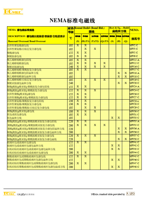
NEMA标准电磁线
105
X
X
-
- - - MW3-C
155 X X
-
-
- - - MW5-C
105 X X
-
-
- - - MW6-C
105 X X
-
-
- - - MW15-A
105 X X
X
X - - - MW15-C
240 X X
X
X - - - MW16-C
105 X X
-
-
- - - MW17-C
105 - -
(S) (H)(T1) (T)(T2) (Q)(T3) (S) (H) (Q)
高温有机漆粘结玻璃丝包或玻璃丝包漆包线
180 X X
-
高温有机漆粘结聚酯玻璃丝包或聚酯玻璃丝包漆包线
180 X X
-
高温有机漆粘结玻璃丝包或玻璃丝包漆包扁和方线
180 - -
-
高温有机漆粘结聚酯玻璃丝包或聚酯玻璃丝包漆包扁和方线 180 -
--
- MW78-C
直焊性聚氨酯漆包线
155 X X
X
--
- MW79-C
直焊性聚氨酯/聚酰胺复合漆包铝线
155 X X
-
-
--
- MW80-A
直焊性聚氨酯/聚酰胺复合漆包线
155 X X
X
--
- MW80-C
聚酰胺酰亚胺漆包线
200 X X
-
-
--
- MW81-C
直焊性聚氨酯漆包线
180 X X X
- - - MW27-C
130 X X
-
-
- - - MW28-A
130 X X
nema23标准

nema23标准
NEMA23标准是一种电机尺寸标准,用于指导电机制造商生产电机的尺寸和安装方式。
NEMA23标准的电机通常用于需要高精度和高扭矩的应用,例如CNC机床、3D打印机和机器人等。
NEMA23标准的电机尺寸为57.15毫米(2.25英寸)正方形,轴径为6.35毫米(0.25英寸)。
这种电机通常有四个螺孔用于安装,螺孔直径为5.08毫米(0.2英寸)。
NEMA23标准的电机有不同的长度,例如单轴电机的长度通常为76.2毫米(3英寸),双轴电机的长度通常为101.6毫米(4英寸)。
NEMA23标准的电机通常有两种类型:步进电机和直流电机。
步进电机是一种精度高、速度慢的电机,适用于需要高精度定位的应用。
直流电机是一种速度快、扭矩大的电机,适用于需要高速运动的应用。
NEMA23标准的电机通常有不同的步距角和电流等级。
步距角是指电机每步转动的角度,通常为1.8度或0.9度。
电流等级是指电机的额定电流,通常为1.5安培或3安培。
不同的步距角和电流等级可以满足不同应用的需求。
总之,NEMA23标准是一种重要的电机尺寸标准,用于指导电机制造
商生产高精度、高扭矩的电机。
不同的步距角和电流等级可以满足不同应用的需求。
Nema MW1000(英寸)标准

43 4.84 0.0151 66,092 141,619 176,611 31,536
26
22
43
42.5 0.0023 0.0024 0.0025 1,626 1,793 1,960 0.0002 0.0025 0.0026 0.0028 0.0004 0.0027 0.0029 0.0031 0.0007 0.003 0.00325 0.0035
42 6.25 0.0195 51,313 85,147 127,551 17,638
34
24
42
41.5 0.0025 0.0026 0.0027 1,394 1,527 1,659 0.0002 0.0027 0.0029 0.0031 0.0005 0.003 0.0032 0.0034 0.0008 0.0033 0.00355 0.0038
12
53
52 0.00075 0.00078 0.00081 15.69 17.05 18.41 0.0001 0.00085 0.00093 0.001 0.0002 0.00095 0.00105 0.00115
52 0.608 0.00196 510,200 19,180 1,155,625 1,642,711
5
16
50
49.5 0.00101 0.00105 0.00109 8.72
9.386 10.371 0.0001 0.0011 0.00118 0.00126 0.0002 0.00121 0.00132 0.00143
49.5 1.1 0.00334 299,400 6,195 718,184 561,740
0.8
8
57
56 0.00047 0.00049 0.00051 39.73 43.19 46.65 0.00005 0.00052 0.00059 0.00065 0.0001 0.0006 0.00071 0.00081
NEMA大小1和2,以及大小1-3 4非反转和反转联接器和启动器说明书
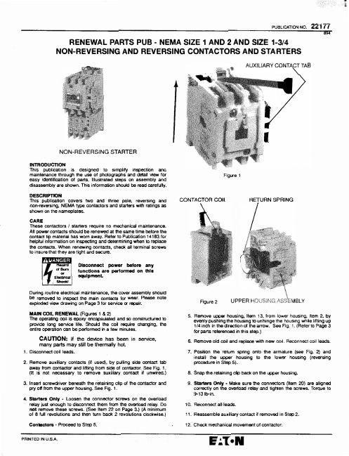
PUBLICATION NO. 22177894 RENEWAL PARTS PUB -NEMA SIZE 1 AND 2 AND SIZE 1-3/4NON-REVERSING AND REVERSING CONTACTORS AND STARTERSNON-REVERSING STARTERINTRODUCTIONThis publication is designed to simplify inspection anamaintenance through the use of photographs and detail view foreasy identification of parts. Illustrated steps on assembly anddisassembly are shown. This information shouk:J be read carefully.DESCRIPTIONThis publication covers two and three pole, reversing andnon•reversing, NEMA type contactors and starters with ratings asshown on the nameplates.CAREThese contactors / starters require no mechanical maintenance.All power contacts should be renewed at the same time before thecontact tip material has wom away. Refer to Publication 14183. forhelpful information on inspecting and determining when to replacethe contacts. When renewing contacts, check aU terminal screwsto insure that they are tight and secure.I •Hazanlof BumEl�cal,.._,Disconnect power before anyfunctions are performed on thisequlpmenLDuring routine electrical maintenance, the cover assembly snouicibe removed to inspect the main contacts for wear. Please noteexploded view drawing on Page 3 for service or repair.MAIN COIL RENEWAL (Figures 1 & 2)The operating coil is epoxy encapsulated and so constructured toprovide long service life. Should the coil require changing. theentire operation can be performed in a few minutes.CAUTION: If the device has been in service,many parts may still be thermally hot.1 . Disconnect coil leads.2. Remove auxiliary contacts (if used), by pulling side contact tabaway from contactor and lifting from side of contactor. See Fig. 1.(It is not necessary to remove auxiliary contact if unwired.)3.Insert screwdriver beaeath the retaining clip of the contactor andpry off from the upper housing. See Fig. 1.4. Starters Only -Loosen the connector screws on the overloadretay just enough to disconnect them from the overload relay. Donot remove these screws. (See Item 22 on Page 3.) (A minimumof 8 full revolutions and then tur n back 2 revolutions clockwise.)Contactora • Proceed to Step 5.Figure 1CONTACTOR COIi RETURN SPRINGFigure 2 UPPER HOUSING t'.SSEMBLY5. Remove upper housing, Item 13, from lower housing, Item 2, byevenly pushing the housing to unhinge the housing while lifting up1/4 inch in the direction of the arrow. See Fig. 1. (Refer to Page 3for parts referenced in this step.)6. Remove old coil and replace with new coil. Reconnect coil leads.7. Position the retum spring onto the armature (see Fig. 2) andinstall the upper housing to the lower housing (reversingprocedure in Step 5).8.Snap the retaining clip back on the upper housing.9.Starters Only • Make sure the connectors (Item 20) are alignedc orrectly on the overload relay and tighten the screws. Torque to!H311>-in.1 0. Reconnect all leads.11.Reassemble auxiliary contact if removed in Step 2.12. Check mechanical movement of contactor.PAINTED IN U.S.A.'ii221 n P UBLICATION NO.MAIN COILSControl VoltaaeMain Coil Volts Hertz Part No.(1 Reqd/Contactor)2450/60 9-2703-16110/120 50/60 9-2703-1220/240 50/60 9-2703-2440/480 50/60 9-2703-3550/600 50/60 9-2703-4277 60 9-2703-7208 60 9-2703-948 60 9-2703-1124 60 9-2703-6380/415 50 9-2703-8240 50 9-2703-1448 50 9-2703-1332 50 9-2703-1024509-2703-12DC COILS'Voltage 12 24 48 120Main Coil Part No.( 1 Reqd/Contactor)9-2990-19-2990-29-2990-39-2990-4•Must be used with C320KGD4 (N.C.) or C320KGD5 (N.O.-N.C.)auxiliary contactsMAIN CONTACT RENEWAL (Figures 3, 4, 5, & 6)Disassembly1.Disconnect all power to the contactor/starter.2.Loosen the two gold-colored screws and remove the arc chuteassembly from the contactor.3.Arc Chutes -Remove arc chutes from contactor by placing a screwdriver in the small hole of the arc chute and prying up (Fi g .4).4.Movable Contacts • Insert a small screwdriver into the contact springs and pry springs out of contact bar {Fig. 5). Refer to Sketch "A•. Rotate contacts as shown and remove from contact bar.5.Stationary Contacts -Remove main wiring. Insert a small screwdriver underneath the stationary contacts and pry contacts out of housing (Fig. 6). Starters Only -Remove overload relav from contactor.Reassembly6.Install new arc chutes into contactor arc chute assembly. Make sure arc chutes are pressed in tightly.7.Install new stationary contacts into contactor housing, making sure that contacts seat firmly.8.Install new movable contacts into contact bar. Compress contact springs between thumb and forefinger and insert springs so that springs engage both detents of contact and contact bar.9.Install arc chute assembly onto contactor and torque gold-colored screws to 15 lb-in.ARC CHUTE ASSEMBLYFigure 3Figure 5PAGE2q" •·Figure 4CONTACT BARSketch 'A'Figure 6PRINTED IN U.S.ArrEM NO.12 3 4 5 8 7 8 9101112131415161718PUBLICATION NO. 221771821RENEWAL PARTS -Information RequiredTo insure prompt handling of renewal parts order, please include the following:DESCRIPTION, PART NUMBER, AND QUANTITY REQUIREDPARTS LISTPART QUANTITIES rrEM PARTDESCRIPTION NUMBER CN15 AN18 CNS5 AN56 NO. DESCRIPTION NUMBERMounting Plate (contactors)-19 Overload Relay (includes C306GN3Size , , 1-3/4, and 2 Items 20, 21, & 22)Non-Reversing C321MP2 1---20 Bus Bar Connector (includesReversing C321MP9 -- 1 -Item 22):Lower Housing 49-7419 1 1 2 2 Size 1 Starter 25-10219-2StlOCk Pad 32-1697 2 2 4 4 Size 1-3/4 & 2 25-10219-3Magnet Frame • 17-18200 1 1 2 2 21 10-32 x .750 PH Sems Screw 11--5174Coil Bias Spring 69-4747 2 2 4 4 22 8--32 x .203 Sems Screw 11-6194Magnet Coil See Page 2 1 1 2 2 23 Auxiliary Contact See Page 4Return Spring 69-4771 1 1 2 2 24 Renewal Contact Kit ••Armature Assembly • 48-1833 1 1 (incl Items 11, 12, 14, & 15)Armature Retainer 69--6129 1 1 2 2 Size 1 2 Pole 6-65Contact Carrier 23-6337 1 1 2 2 3 Pole 8-65-2Movable Contact See Item 24 ----Contact Spring See Item 24----Size 1-3/4 2 Pole 6-65-5Upper H0USlng (without 3 Pole 6-65-6markings) 49,.7421 1 1 2 2Stationary Contad Assembly See Item 24 --Size2 2 Pole 6-65-7Arc Chute See Item 24---- 3 Pole 6-65-8Cover Assembly (without 25 Mechanical Interlock C321KM60Bmarkings) {not shown)(Also indudesCN15---2 -2111 -111QUANTrrlESAN16 CN5513-3-4 43-1 21-1 21-1 211 2- 1Items 15 & 17) -It is recommended that Items 4 and 8 be replaced together.2 Pole 49-7425-2 1---.. Recommended spare parts_3 Pole 49-7425 1 1 2 2Cover Screw 11-4989 2 2 4 4Mounting Ptate (starters) - 1 1 1 1Size 1, 1-3/4, &2Non-Reversing C321MP4 1Reversing C321MP12 - 1AN56133634-2-2-21AINTED IN U.S.A. PAGE3221 nPUBUCATION NO. RENEWAL OF OVERLOAD (Figure 7)The bimetal, ambient compensated overload relay is adjustable within the FLA ranges of the heater packs. Each heater pack is marked with range of FLA ratings.Select heater packs (3 required) according to the motor FLA rating, and install in overload relay. Rotate the FLA adjustment dial to a position corresponding to the motor FLA. Consult overload relay publication supplied with the starter for proper setting and selection. The overload relay is factory set for manual operation. If automatic reset is required, turn the reset adjustment dial to "A" or "AUTO".THE ENTIRE OVERLOAD RELAY MUST BE REPLACED IF BURNOUT OF THE HEATER PACK OCCURSDo not disassemble the overload relay! LubricationDo not lubricate any part of this equipment.ACCESSORIESTop Mounted Auxiliary ContactsDescriptionStandardLogic LevelCatalog N o. Gatalog N o. 1 N.O. C320KGT1C320KGT1L1 N.C. C320KGT2 C320KGT2L 1 N .O. -1 N.C.C320KGT3 C320KGT3L 2N.O. C320KGT4 C320KGT4L 2N.C.C320KGT5 C320KGT5L 3N.O. C320KGT9 C320KGT9L 3N .C. C320KGT12 C320KGT12L 4N.O. C320KGT13 C320KGT13L 4 N.C.C320KGT17C320KGT17LTransient SuppressorPneumatic TimerCatalog No. Coil Voltage Description Catalog No.C320TS1 120V 0.1 to 30 sec. C320TP1 C320TS2 240V 10 to 30 sec.C320TP2C320TS3480VPAGE4Fig. 7 -Overload RelaySide Mounted Auxlllary ContactsDescriptionStandai-d Logic Level Catalog No. Catalog No. 1 N.O. C320KGS1 C320KGS1L 1 N.C. C320KGS2 C320KGS2L 1 N.O. -1 N.C.C320KGS3 C320KGS3L 2N.O. C320KGS4 C320KGS4L 2N.C. C320KGS5 C320KGS5L1 N.C. C320KGD4 -1 N.O. -1 N.C.C320KGD5-NOTE: For a complete list of available top and sidemounted auxiliary contacts. see your local Eaton/Cutler-Hammer representative. *Used with DC magnet coil.Electronic TimerDescriptionCatalog N o.120VAC/DC 240VAC/DC0.3 to 3 sec.C320TM3AC320TM3B3 to 30 sec.C320TM30A C320TM30B 30 to 300 sec. C320TM300A C320TM300B PRINTED IN U.S.A.。
NEMA接地与电源应用的高效螺栓连接片说明书

CATALOG NUMBERB101JHFEATURES为接地和电源应用提供高效螺栓连接表面电解级铜仅与 nVent ERICO Cadweld 型 LA 连接一起使用产品属性Material: 铜Finish: 镀锡Type: NEMA®长度:85.85 mmWidth: 50.8 mm厚度:12.7 mmA:25.4 mmHole Size: 14.29 mmEquivalent Conductor Size: 645.03 mm²ADDITIONAL PRODUCT DETAILS有关未列出的尺寸,请联系我们。
DIAGRAMS警告应仅根据 nVent 的产品说明书与培训材料安装并使用 nVent 的产品。
可访问 获取说明书,或者向您的 nVent 客服代表索取。
错误安装、使用不当、滥用或未能完全遵守 nVent的说明与警告,可能会造成产品故障、财产损失、严重的人身伤害及死亡和/或使得保修服务无效。
北美+1.800.753.9221Option 1 – Customer CareOption 2 – TechnicalSupport 欧洲Netherlands:+31 800-0200135France:+33 800 901 793 欧洲Germany:800 1890272Other Countries:+31 13 5835404 APAC Shanghai:+ 86 21 2412 1618/19Sydney:+61 2 9751 8500 CADDY ERICO HOFFMAN RAYCHEM SCHROFFTRACER2。
Nema MW1000(英寸)标准

典型 拉伸率
标称直径
[AWG]
下限 [英寸]
标准 [英寸]
上限 [英寸]
下限
[欧姆/1000 英尺]
标准
[欧姆/1000 英尺]
上限
[欧姆/1000 英尺]
[英寸]
下限 [英寸]
标准 [英寸]
上限 [英寸]
[英寸]
下限 [英寸]
标准 [英寸]
上限 [英寸]
[英寸]
下限 [英寸]
标准 [英寸]
上限 [英寸]
6
15
49.5
49 0.00107 0.00111 0.00116 7.744 8.417
9.09 0.0001 0.00117 0.00124 0.0013 0.0002 0.00127 0.00139 0.0015
49 1.23 0.00385 259,700 4,810 649,636 456,176
45 3.1 0.00965 103,600 746,000 271,441 75,683
17
20
45
44.5 0.0018 0.0019 0.002 2,451 2,871 3,201 0.0001 0.0019 0.0021 0.0023 0.0004 0.0022 0.0024 0.0026 0.0006 0.0024 0.00265 0.0029
7
17
49
48.5 0.00113 0.00117 0.00122 7.008 7.585 8.123 0.0001 0.00123 0.00131 0.00141 0.0002 0.00133 0.00144 0.00155
48.5 1.37 0.00414 241,500 4,039 582,717 368,325
