EM241_快速入门
安利达 720P 无线数字安防摄像头 LW3211 系列快速启动指南说明书

LW3211 SERIES QUICK START GUIDE
Getting Started
This system comes with the following components: 1x wireless camera 1x wireless receiver 1x antenna for camera 1x antenna for receiver 2x power adapters (for camera and receiver) 1x camera mounting kit 1x receiver mounting kit
NOTE: The camera and receiver have already been paired out of the box. If for some reason the pairing is lost, follow these steps to pair up the camera and receiver.
A. Installing the Camera
1 Mount the camera to the wall or ceiling using the included screws. Use the included anchors as needed.
NOTE: If you run the cables along the wall / ceiling, you must run the cable through the cable notch on the base. This will keep the camera base flush to the wall / ceiling when mounted.
重新整理3000份电气资料书籍视频-PLC,电力,数控,变频,电机,电工,维修
加QQ1405061620 PLC部分
哈工大S7-200西门子PLC视频教程 西门子s7-400视频 欧姆龙PLC视频教程1-40集 三菱FX系列PLC视频 西门子S7-300-400 PLC 应用技术 ABB 技术培训教材 CP243-1 快速入门 《大中型PLC应用教程》廖常初 主编 PLC_技术培训班_(第1讲)基本原理 PLC_技术培训班_(第2讲修改稿)STEP_7编程软件 PLC_技术培训班_(第3讲)梯形图指令系统介绍 PLC_技术培训班_(第4讲)IEC61131-3_标准 PLC_技术培训班(第5讲)现场总线介绍 PLC_技术培训班_(第6讲)WinCC组态软件介绍 PLC_技术培训班(第7讲)Ethernet介绍 PLC_技术培训班_(第8讲)ProTool组态软件介绍 PLC程序范例大全 PLC多轴运动控制平台推荐方案 plc可编程控制器(工控常用范例大全) PLC可编程控制器系统开发实例导航 PLC课件 PLC行业应用实践 PLC应用开发技术与工程实践 (第二版)
电厂电气部分视频教程 电力系统自动装置视频教程 电气主接线视频教程 高压电技术视频教程 继电保护72讲 继电保护(郑州大学) 三菱变频器视频教程 数字电子技术 自动控制原理30集 电动机维修 数控技术
电工电子技术
可编程设计范例大全 流水线PLC控制s7-200使用手册 三菱PLC基本指令 三菱PLC应用101例 三菱通用伺服系统培训资料 深入浅出西门子S7-200PLC (第2版) 深入浅出西门子S7-300PLC 数控系统维修手册 梯形图(LAD)编程手册 图解PLC控制系统梯形图及指令表 西门子 S7-300 PLC 从入门到经典问题及解答
昆仑通态视频教程 威纶通eb8000视频教程
威纶通eb500视频教程 三维力控视频教程 组态王6.53视频教程 世纪星组态视频教程 pcs7视频教程 intouch的视频教程 紫金桥组态视频教程 WinCC flexible WinCC 电脑装机全过程 cad electrical 2009 proe实例教程集 vb视频教程大全 数据结构视频教程 oracle视频教程 autocad electrical视频 delphi7.0视频教程(68集) eplan_p8_快速入门视频 单片机 三菱伺服视频教程 三菱步进视频教程 高压电气实验工培训片 液压动画视频教程大全
PC_Access_快速入门
PC Access快速入门PC Access Getting Started摘要本文对西门子提供的OPC服务器软件PC Access的基本设置进行了简单的介绍,并列举了一些简单的应用,常见问题。
关键词PC Access,OPC,WinCC,WinCC Flexible,应用Key Words PC Access, OPC, WinCC, WinCC Flexible,ApplicationIA&DT Service & Support Page 2-29目录PC Access快速入门 (1)1. 概述 (4)1.1 介绍 (4)1.2 与Windows操作系统的兼容性 (4)1.3 PC Access 支持的通信协议 (4)1.4 PC Access 主要的硬件连接 (5)1.5 PC Access 的注意事项 (5)2. PC Access 的基本设置 (5)2.1 PC Access 的主界面 (6)2.2建立PLC连接 (6)2.2.1 通过PC/PPI电缆通信 (6)2.2.2 通过以太网通信 (8)2.2.3 通过Modem(调制解调器)通信 (9)2.3 建立项目 (13)2.4 使用客户机测试端 (14)3.PC Access的典型应用 (15)3.1 PC Access与WinCC的以太网通信 (15)3.2 PC Access 与 WinCC flexible RT的通信 (21)3.3 PC Access 与 Excel的通信 (22)3.4 将S7-200项目中的变量导入 PC Access (24)4. 常见问题 (24)IA&DT Service & Support Page 3-291. 概述1.1 介绍西门子推出的PC Access 软件是专门用于S7-200 PLC的OPC服务器( Server)软件,可以与任何标准的OPC客户端(Client)通信并提供数据信息。
S7-200_EM241_使用快速入门
1 2 3 4 1. 在此选择模块是否要密码保护,选择密码保护后,任何人要通过 EM241 连接到该PLC都必须提供密码。 2. 在此处填写密码。 3. 在此处确认密码。 4. 点击 Next> 按钮。
A&D Automation System in China
EM241 快速入门
通讯选择
S7-200 & S7-200
1. 填写模块所占用的Q存储区的地址,建议您使用默认的地址。 2. 点击 Next> 按钮 。
A&D Automation System in China
EM241 快速入门
通讯选择
S7-200 & S7-200
S7-200 & S7-200
配置主叫端 配置被叫端
21-xXXx 或更新版本。
通过电话网编程 配置EM241 配置Micro/WIN
• 两个EM241, 订货号为 6ES7 241-1AA22-0XA0 。 • 两根程控电话线,或者电话交换机和电话线。
S7-200 & WinCC 配置EM241 配置WinCC
S7-200 & S7-200
配置主叫端 配置被叫端
通过电话网编程 配置EM241 配置Micro/WIN
3
1
4
2
A&D Automation System in China
EM241 快速入门
通讯选择
1. 点击 Properties… 能够对所有 可供使用的号码进行修改或删除。
S7-200 & S7-200
配置主叫端 配置被叫端
2. 在此输入要向远程PLC写入的字 节长度。 3. 在此输入数据源的起始地址。 4. 在此输入数据目的地的起始 地址。
健伍TM241A说明书

健伍TM-241A/441A中文操作说明由原版英文说明书翻译而得编译:马玉成2003年11月于大连目录1 使用前的注意事项 (4)2 规格参数 (6)3 随机附件 (7)4 安装 (8)5 操作控制部件及功能 (10)接收接收 (16)频率选择 (17)频率步长选择 (17)可编程频率方式(VFO)调谐限制 (18)ALT(仅对TM-541A/E有效) (19)发射 (20)超时定时器(TOT) (20)存储器后备电池 (21)初始状态 (21)初始化 (21)存储信道 (21)存储目录 (22)存储信道的存入 (22)存储信道的调出 (24)存储转移 (24)扫描扫描 (25)挂起/恢复 (25)频段扫描 (26)可编程频段扫描 (26)存储信道扫描 (27)存储信道跳过 (27)优先信道报警 (28)使用中继频差设定 (28)倒频功能 (29)亚音 (29)亚音频率选择 (29)自动补偿(仅对美国版有效) (30)连续单音静噪(CTCSS) (30)双音频静噪(DTSS) (31)数字录音(DRS) (34)分组 (41)音频报警 (47)自动关闭电源(APO) (48)屏幕背光(DIM) (48)提示音 (49)按键锁定 (49)6 电路图7 维修 (50)8 可选附件 (52)2 规格参数5 操作5-1-1 控制部件及功能①电源开关(POWER)接通或关闭电源。
按下VFO键或MR键同时接通电源将清除频率方式或存储信道的频率信息。
当电源接通时,手柄上的PF键可以编程。
②调谐旋钮选择发射或接收频率、存储信道、频率步长、亚音频率、扫描方向等。
③音量旋钮(VOL)调整扬声器的音量,顺时针方向转动将增大音量,逆时针方向转动减小音量。
④静噪旋钮(SQL)选择静噪阀值。
⑤功率/背光键(LOW/DIM)功率选择发射输出功率的大小(HI:高,MID:中,LOW:低)背光选择显示屏幕的背光亮度。
按住功能键(F)1秒钟以上,当F 显示闪烁时再按此键将开启或关闭超时定时器。
MODEM模块EM241使用入门
• PC/PPI 电缆或者 CP5611/5511/5411 和MPI电缆。 • 两个CPU22X,订货号6ES7 xxx-xxXX
21-xXXx 或更新版本
• 两个EM241, 订货号为 6ES7 241-1AA22-0XA0
1 1. 在此处选择模块的位置。
2
3
2. 在线的情况下,您也可以用Read Modules按钮搜寻在线的EM241模块。
3. 点击Next>按钮。
A&D Automation System in China
EM241 快速入门
通讯选择
S7-200 & S7-200 •配置主叫端 •配置被叫端 S7-200 & Micro/WIN •配置EM241 •配置Micro/WIN •连接
WinCC & S7-200
•配置EM241 •配置WinCC
2
1
A&D Automation System in China
EM241 快速入门
通讯选择
S7-200 & S7-200 •配置主叫端 •配置被叫端 S7-200 & Micro/WIN •配置EM241 •配置Micro/WIN •连接
EM241 快速入门
通讯选择
S7-200 & S7-200 •配置主叫端 •配置被叫端 S7-200 & Micro/WIN •配置EM241 •配置Micro/WIN •连接
当然了! 我们现在已经有EM241 调制解调器模块了!
我能用S7-200连公共电话网吗?
WinCC & S7-200
S7-200系列PLC与WINCC通过以太网进行OPC通信
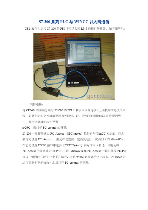
S7-200系列PLC与WINCC以太网通信CP243i作为连接S7-200的PPI口转以太网RJ45的接口转换器。
如下图所示:一、硬件连接:将CP243i的两端分别与S7-200的PPI口和以太网线连接(上图使用的是交叉网线,如果中间加交换机就要用直连网线,注:我们平时用的都是直连型网线)二、监控计算机的软件设置:a.OPC—西门子PC_Access的设置:S7-200一般都是通过PC_Access(OPC server)软件再与WinCC相连的。
因此要首先设置PC_Access,但是在设置前一定要先运行一次西门子的MicroWin ,在它的设置PG/PC接口中选择[ TCP/IP(Auto) 实际的网卡名],目地是将PC_Access的驱动选为TCP/IP,(注:MicroWin和PC_Access中均可修改PG/PC 接口,但同时只能有一个正在运行,并且wincc必须处于停止状态,若wincc为运行状态则不能修改)之后打开PC_Access,见下图:用鼠标右健点击[ MicroWin(TCP/IP) ],然后用鼠标左键选择[ 新PLC(N)… ]打开PC Access之后,弹出上图,一个新的PLC连接属性窗口,名称自定义,IP 地址和TSAP本地和远程地址需在MicroWin中以太网向导中找寻,如下图:进入MicroWin之后,在工具栏中找到以太网向导,进入以太网设置,如下图:IP地址出现后,按下一步,直到出现配置连接,出现TSAP设置,如下图:将PC_Access,中PLC属性窗口填写正确后,如下图:然后直接点击[ 确认] ,进入下图:用鼠标点击[NewPLC] 新(N) 项目(I) ,如下图所示:下边做4个例子:(1)名称:ITEM_VB10,地址:VB10,数据类型:BYTE(2)名称:ITEM_Q0_0,地址:Q0.0,数据类型:BOOL(3)名称:ITEM_I0_2,地址:Q0.2,数据类型:BOOL(4)名称:ITEM_MD20,地址:MD20,数据类型:REAL添加完变量后,一定要存一下盘!至于文件名随便写一个或用缺省的也可建立4个ITEM后,用鼠标安下图次序(1)(2)(3)依次点击,就进入了测试状态如果通讯正常,质量显示为good 否则为badb. 西门子WinCC的设置:打开WinCC,新建一个项目[ test_s7_200]:用鼠标右键点击[变量管理] à添加新的驱动程序(N) à选择OPC.chn用鼠标右键点击[OPC Groups (OPCHN Unit #1) ] à选择[ 系统参数]用鼠标双击[ \\<LOCAL< a>> ] ,搜索本机OPC服务器:选择[ S7200.OPCServer ],再选择[ 浏览服务器] ,选择[ 下一步]将Items栏中内容全部选定,然后点击[添加条目]选择[ 是]选择[ 确定]选择[ 完成],之后PC_Access中的变量就来到WinCC中:前两天有一个类似的问题,OPC是必需的,可以用PC Access(7-200专用的OPC,8个连接限制),也可以用Simaic Net(S7 PLC通用的,最多64个连接)。
E2 3D Printer快速入门指南说明书
E23D Printer Quick Start Guide* Please review this entire guide before operating the printer.CONTENTSSafety (1)Electromagnetic Compatibility - EMC (2)Technical Specifications (4)Printer Components and Parts (6)Raise3D Supplies and Accessories (10)Precaution and Hardware Installation (11)Software Installation (13)WLAN Connection (20)Maintenance (21)Start Printing (23)User Interface (24)Experiencing Difficulties/Contact Information (25)SafetyWarning: Indicates a potentially hazardous situation which, if not avoided, may result in injury or damage.Hot Nozzle: The hot nozzle sign indicates the presence of devices with high temperatures. Always use extra care when working around heated components. Always wear the heat resistant gloves provided in the Starter Box when working near the nozzle.Nozzle temperatures in the printer can reach 300℃(572℉).Hot Surface:The hot surface sign indicates the presence of devices with high temperatures. Always use extra care when working around heated components. Always wear the heat resistant gloves provided in the Starter Box when working near hot surfaces.Moving Parts: The moving parts sign indicates that a hazard exists. If touched, it can cause serious bodily injury. Always keeps hands clear of moving parts.High Voltage: The high voltage sign indicates the presence of high voltages. Always stay away from exposed circuitry. It is recommended that all conductors be removed.Electromagnetic Compatibility - EMC⚫Simplified EU Declaration of ConformityRaise3D declares that this device is in compliance with the essential requirements and other relevant provisions of Directive 2014/53/EU. Full text of the EU declaration of conformity is available at https://.- 2 -⚫FCC StatementThis device and its antenna must not be located or operated in conjunction with any other antenna and transmitter.This device complies with part 15 of the FCC rules. Operation is subject to the following two conditions: (1) this device may not cause harmful interference, and (2) this device must accept any interference received, including interference that may cause undesired operation.NOTE: The manufacturer is not responsible for any radio or TV interference caused by unauthorized modifications to th is equipment. Such modifications could void the user’s authority to operate the equipment.NOTE: This equipment has been tested and certified to comply with the limits of a Class B digital device, pursuant to part 15 of the FCC Rules. These limits are designed to provide reasonable protection against harmful interference in a residential installation. This equipment generates uses and can radiate radio frequency energy and, if not installed and used in accordance with the instructions, may cause harmful interference to radio communications. However, there is no guarantee that interference will not occur to a particular installation. If this equipment does cause harmful interference to radio or television reception, which can be determined by turning the equipment off and on, the user is encouraged to try to correct the interference by one or more of the following measures:-Reorient or relocate the receiving antenna.-Increase the separation between the equipment and receiver.-Connect the equipment into an outlet on a circuit different from that to which the receiver is connected.RF exposure information: This equipment complies with FCC radiation exposure limits set forth for an uncontrolled environment. This equipment should be installed and operated at a minimum distance of 20cm between the radiator and your body.Changes or modifications not expressly approved by the party responsible for compliance could void the user’s authority to operate the equipment.Technical Specifications- 4 -The firmware is based on RepRapFirmware (https:///dc42/RepRapFirmware)The electronics inspired by Duet3D.DUET 2 WIFI and DUET 2 ETHERNET LICENSEThe Duet WIFI/ DUET 2 WIFI and DUET ETHERNET are licensed under the terms of the CERL OHL 1.2 (see below or /attachments/2388/cern_ohl_v_1_2.txt for full text) will the following additional conditions:a.Attribution:Any reproductions or modifications of the hardware must contain the following attribution on the silkscreen and packaging:"Based on the DuetWifi by Think3dPrint3d and Esher3d, see for the original DuetWifi information. This reproduction/modification is not endorsed or supported in any way by Think3dPrint3d or Escher3d".b.Logos:No reproduction or modification of the Duet 2 Wifi or Ethernet hardware may contain the Think3dPrint3d, Escher3d or Duet3d logos.Shouldyouneedanyfurtherinformation,*************************************************.Printer Components and Parts1.Front PartsA.Air Filter BoxContains the air filter, which can filter out part of the harmful gas produced in the printing process.B.ExtruderFeeds the filament into the hotend.C.HotendThe hotend consists of a nozzle, heater block, thermocoupler, heater rod, throat tube, and heat sink.D.Platform TrayThe Platform Tray is highly magnetized to ensure that the build plate stays in place.E.Touch ScreenOn-board computing system to display printer status, error messages, and receive commands.F.Power Saving ButtonQuick press to put the screen and LED in sleep/wake mode; Long press for 10 seconds to restart.G.Filament BoxHolds the filament that will be printed.H.Flexible PlateYou can easily remove your models after they've finished printing by bending the plate.F.Power Saving ButtonG.Filament BoxH.Flexible PlateA.Air Filter BoxB.ExtruderC.HotendD.Platform TrayE.Touch Screen2.Back PartsA.Electric Control SystemIncludes screen components and the motion control panel. Do not open without permission.B.CameraUsed to observe the operation of the printer.C.LED Light BarProvides interior lighting of the chassis.D.Filament HolderHolds the filament spool, maximum weight 3 kg.E.Input PowerAC input and switching.F.Filament ExitThe filament leads from here to the extruder.G.Filament Run-out SensorDetects when the material has run out.F.Filament ExitG.Filament Run-out SensorI.Air Filter FanH.Switching Power SupplyJ.Ethernet PortA.Electric ControlSystem B.Camera C.LED Light BarD.Filament HoldersE.Input PowerH.Switching Power SupplySwitches from alternating current to direct current. Please be careful, it’s dangerous! Do not remove the power box without permission.I.Air Filter FanPulls air out of the machine through the air filter.J.Ethernet PortRJ45 port to connect the printer to a network.3.Other PartsA.Z-axis Endstop Limit SwitchLimits the maximum position in the Z direction and provides a Z-axis zero reference.B.Extruder (Left/Right)Feeds the filament into the hotend.C.X-axis Guide RailGuides the extruder’s movement along the X-axis.D.X-axis Motor (Left/Right)Respectively controls the corresponding extruder for horizontal movement.E.Z-axis Motor (Left/Right)Controls both ends of the X-axis beam for synchronous lifting movements.D.X-axis Left MotorA.Z-axis Endstop Limit SwitchB.Left ExtruderB.Right ExtruderC.X-axis Guide RailD.X-axis Right MotorE.Z-axis Right MotorE.Z-axis Left MotorC.X-axis Guide RailRaise3D Supplies and AccessoriesPower Cable(×5)Hex Wrenches Filament(×2)TweezersHeat Resistant Gloves Spatula FilamentGuide Tube(×2)Nozzle Cleaning Kit(×1)Filament Holder(×4)USB Storage Fuse0.3 mm Feeler Gauge(×1)Filament Box Block(×4)quick connector(×2)Plastic rivet(×4)- 10-Precaution and Hardware Installation⚫Read the entire installation section before starting installationConnect equipment to a grounded facility power source. Do not defeat or bypass the ground lead. •Know the locat ion of equipment branch circuit interrupters or circuit breakers and how to turn them on and off in case of emergency.•Know the location of fire extinguishers and how to use them. Use only ABC type extinguishers on electrical fires.•Know local procedur es for first aid and emergency assistance at the customer facility.•Use adequate lighting for the equipmen t.•Maintain the recommended range of temperature and humi dity in the equipment area.•Do not use this product in an environment containing volati le or flammable compounds.⚫Environmental requirements•E2 is for indoor use only.•Excessive solids (conductive or non-conductive) in the air may cause system damage.•The accumulation of oil in the air can damage the plastic parts of the printer.•Th e operating temperature should be in the range of 15°C to 30°C, with a relative humidity range of 10% to 90%without condensation. The storage temperature shall be in the range of -25°C to 55°C, and the relative humidity range shall be 10% to 90% non-condensation.•The altitude shall not exceed 2,000 meters.•Noise (Acoustics) : <50dB(A) during printingNOTE: E2 printers may generate vibrations which depend mainly on the geometry of parts being printed and material characteristics. This will need to be taken into account if locating the printer near vibration sensitive equipment. Please note that during transportation in low temperatures, there is a chance the machine may frost or freeze. The printer can resume use after being kept 4 - 6 hours in an area that is room temperature.⚫Input supply connection and groundingDuring installation, the main outlet socket should be protected according to appropriate rules. Check the input voltage, phase, and frequency supplied to this machine before turning it on. Verify the connection of grounding wires from the machine to the input source. The allowable input voltages are 1x (90-240)V 50Hz/60Hz. For more information about input supply refer to the technical specification section of this manual and to the rating plate of the machine. Make sure the amount of power available from the input connection is adequatefor normal operation of the machine.⚫Hardware Installation and First PrintUse hands to remove the Z-axis and X-axis locks.Please carefully store the removed locks, so thatthey can be installed again and used insubsequent transportation.The top foam contains five power cords ofdifferent standards. Please use the power cordthat conforms to your current country (or region)and connect it to the power socket. Turn on theswitch and start the device.Turn on the power and the printer will enter theboot process. Your Raise3D printer will take about60 seconds to boot. When the touch screendisplays the "Welcome" window, the printer isready. Then you can finish the installation andfirst print according to the Setup guide.Software Installation⚫ideaMaker InstallationThe slicing software, ideaMaker, is availableon the USB storage device included with yourprinter.Additional downloads and versions areavailable online at:https:///download/➢Open the installer and choose your preferred language. Select your preferred installation location for ideaMaker, and click "Next".➢Follow the instructions provided by the guide, and click "Install". After the installation is finished, click "Next"to go to the next step.➢Click "Finish" and ideaMaker is installed.Open the Disk Image for the ideaMaker installer. This is located in the USB storage device included with your printer. Alternatively, you can download the latest version from https:///download/. Next, drag the ideaMaker icon(left) into the Application folder on the right side.⚫ideaMaker Initial Settings➢When launching ideaMaker for the first time, you will need to select your printer model. Select "printer setting" and choose the type of the printer you are using, then press "Next".➢Select the diameter of your filament. Press "Finish" to finalize the initial settings.NOTE: ALL E2 printers use 1.75 mm filaments.⚫Using ideaMaker➢Click the "+" button to import "Giveaway Spinner" included in the USB storage device.➢Click the "Start" or "" button to begin slicing the model.➢Confirm your printer type and material are correct, then select the standard slicing template.Click "Edit" to select the type of Platform Addition and the type of Support.➢Click "Save and Close" to return to the previous menu. Click "Slice" to generate your file.➢Save the sliced files (.gcode and .data) by exporting them to the included USB storage device.NOTE: File names that do not conform to the Western Latin character set may not display properly.➢Confirm that the files are saved and eject the USB storage device.WLAN ConnectionYou can connect to a network by selectingthe SSID and inputting the password. Whenthe Wi-Fi module is manufactured, 2.4G isset at HT20, 5GHz is set at HT40.Note: The Wi-Fi’s frequency is fixed beforebeing manufactured. The customer is notallowed to modify the Wi-Fi’s parameters.(If needed, please contact our tech supportteam).Alternatively, you can select "Add OtherNetwork" and input a name and password.MaintenanceThe printers are pre-leveled at the factory, butwe recommend verifying that the leveling has notchanged during shipping.How to level up the X-axis:As shown in figure 1, click "Maintenance" to levelup the X-axis and it will touch the top beam untilhorizontal.Click the "Utilities" menu and home the Z-axis.Press the upward arrow to lift the Z-axis about0.3 mm-0.7 mm.Check the distance between the nozzle and theprinting platform. After pushing the left extruderto the center position on the platform, loosen thenozzle screw.Take out the gauge from the Accessory Kit and insert it between the nozzle and the platform. Adjust the nozzle so that the distance between the nozzle and the printing platform exactly matches the thickness of the gauge (about 0.3 mm).Tighten the nozzle screw and remove the gauge. The other nozzle is adjusted in the same way.Follow the steps shown in the figure on the touch screen to run 9-point automatic leveling.After the 9 grid interface automatically closes, the leveling is finished.Start PrintingInsert the USB storage device into the USB slot onthe side of the touch screen.Select the "Print" tab, and choose "USB Storage".Select the file and check the printing parametersand settings. Press "Print" to start printing thetest file.During printing, you can check the status of yourprinting, including printing time and otherparameters, from the touch screen in the "Home"interface.NOTE: The touch screen will display an image ofyour model on-screen during printing. This imagewill only be shown when the file is sliced byideaMaker before being uploaded to the printer.User InterfaceHomeTuneExtruder and heatbedtemperatureCurrent model nameTotal print time Current print statusPrint heightStatusPause, Resume and Stop buttonMenu and Settings button TaskbarVisual display of the current model Print parametersMove the axis Loading/UnloadingLevelingVisual display of X/Y/Z axesCoordinate value and Custom edit functionChoose the X/Y/Z axesMove distance "Unit Settings" X/Y/Z axes move and return buttonDisable motor buttonUpload, Resume Print Task, and Print Statistics The storage location of the printed fileUtilitiesPrintExperiencing Difficulties/Contact InformationIf you run into any issues during this guided setup, please contact our expert technicians by creating a ticket at . Customers outside of the US, please contact your local Raise3D distributor or reseller.For sales information please contact us at *****************.Other inquiries: for any other inquiry please send an email to *******************.US Office43 Tesla, Irvine, CA 92618, USA+1 888 963 9028Netherlands OfficeStationsplein 45 Unit A4.004 3013AK Rotterdam, the NetherlandsChina Office4th Floor B5, 1688 North Guoquan Road, Yangpu District, Shanghai 200438 400 6367 888 (For the Mainland of China only)。
MODEM模块EM241使用入门

S7-200 & S7-200 •配置主叫端 •配置被叫端
S7-200 & Micro/WIN •配置EM241
•配置Micro/WIN •连接
WinCC & S7-200 •配置EM241 •配置WinCC
2. 点击 Next 〉。
S7-200 & S7-200 •配置主叫端 •配置被叫端
S7-200 & Micro/WIN •配置EM241
•配置Micro/WIN •连接
WinCC & S7-200 •配置EM241 •配置WinCC
1. 钩选Enable CPU-to-C2PU data tr1ansfer in this configuration复选框, 2. 点击Configure CPU-to-CPU…配置该PLC要读/写的数据。
21 • 两个CPU22X,订货号6ES7 xxx-xxXX -xXXx 或更新版本
• 两个EM241, 订货号为 6ES7 241-1AA22-0XA0
WinCC & S7-200 •配置EM241 •配置WinCC
S7-200 & S7-200 •配置主叫端 •配置被叫端
S7-200 & Micro/WIN •配置EM241
必备条件
S7-200 & S7-200 •配置主叫端 •配置被叫端
S7-200 & Micro/WIN •配置EM241
•配置Micro/WIN •连接
• 带有STEP 7 Micro/WIN32软件的编程设备,软件版本 3.2 SP1以上。 • PC/PPI 电缆或者 CP5611/5511/5411 和MPI电缆。
DELL vostro 2420用户手册

Dell Vostro 2420用户手册管制型号: P22G管制类型: P22G004注、小心和警告备注: “注”表示可以帮助您更好地使用计算机的重要信息。
小心: “小心”表示可能会损坏硬件或导致数据丢失,并说明如何避免此类问题。
警告: “警告”表示可能会造成财产损失、人身伤害甚至死亡。
© 2012 Dell Inc.本文中使用的商标: Dell™、 DELL 徽标、 Dell Precision™、 Precision ON™、ExpressCharge™、 Latitude™、Latitude ON™、 OptiPlex™、 Vostro™和 Wi-Fi Catcher™是 Dell Inc. 的商标。
Intel®、 Pentium®、 Xeon®、 Core™、 Atom™、 Centrino®和 Celeron®是 Intel Corporation 在美国和/或其他国家或地区的注册商标。
AMD®是注册商标, AMD Opteron™、 AMD Phenom™、AMD Sempron™、 AMD Athlon™、 ATI Radeon™和 ATI FirePro™是 Advanced Micro Devices, Inc. 的商标。
Microsoft®、 Windows®、 MS-DOS®、 Windows Vista®、Windows Vista 开始按钮和 Office Outlook®是 Microsoft Corporation 在美国和/或其他国家或地区的注册商标。
Blu-ray Disc™是 Blu-ray Disc Association (BDA) 拥有的商标,经其许可在磁盘和播放器上使用。
Bluetooth®文字标记是 Bluetooth® SIG, Inc. 拥有的注册商标,Dell Inc. 经其许可使用这些标记。
S7-200之间通讯方式
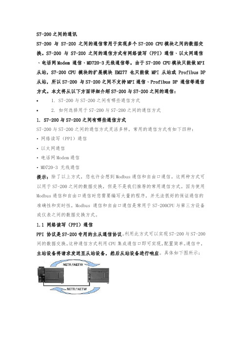
S7-200之间的通讯S7-200 与 S7-200 之间的通信常用于实现多个S7-200 CPU模块之间的数据交换。
S7-200 与 S7-200 之间的通信方式有网络读写(PPI)通信﹑以太网通信﹑电话网Modem 通信﹑MD720-3无线通信等。
由于S7-200 CPU模块只能做MPI 从站,S7-200 CPU 模块的扩展模块 EM277 也只能做 MPI 从站或 Profibus DP 从站,所以S7-200 与S7-200之间不支持MPI通信﹑Profibus DP 通信等通信方式。
本文将从以下方面详细介绍S7-200与S7-200之间的通信:• 1. S7-200与S7-200之间有哪些通信方式• 2. 如何选择用于S7-200与S7-200之间的通信方式1. S7-200与S7-200之间有哪些通信方式S7-200与S7-200之间的通信方式灵活多样,常用的通信方式有如下四种:•网络读写(PPI)通信•以太网通信•电话网Modem通信• MD720-3 无线通信提示:除了以上方式,您也许会想到Modbus通信和自由口通信。
这两种方式可以用于S7-200之间的数据交换,但是不是我们推荐的常用通信方式。
因为使用Modbus通信和自由口通信时您需要编写大量的程序,并无法很好的保证通信的准确性和实时性,Modbus 通信和自由口通信是常用于S7-200CPU与第三方设备或仪表之间的数据交换方式。
1.1 网络读写(PPI)通信PPI 协议是S7-200专用的主从通信协议。
利用此方式可以实现S7-200与S7-200间的数据交换。
这种通信方式利用CPU集成通信口即可实现,配置简单。
通信中,主站设备将请求发送至从站设备,然后从站设备进行响应。
具体如下图所示:实现网络读写(PPI)通信可以使用以下两种方法:第一,使用Step 7 Micro/Win编程软件中指令向导中的NETR/NETW向导;具体方法和相关注意事项请参考《西门子 S7-200•LOGO!•SITOP 参考》(更新版)S7-200 PLC->通信->网络读写(PPI)通信。
CP341驱动配置

CP341驱动配置在您的计算机上首先安装STEP7 5.x软件和CP34x模板所带的软件驱动程序.模板驱动程序包括了对CP341进行参数化的窗口(在STEP7的硬件组态界面下可以打开)、用于串行通讯的FB程序块。
当系统上电,CP34x模板初始化完成后,CP34x上的sF灯点亮:在硬件组态窗口中双击CP341模板,打开CP341模板的属性窗口,选择通讯协议modbus,网络工作方式设置为半双工,请记录下模板的硬件地址以便在编程序时用到。
双击CP341模板属性窗口中的protocol 协议图标进行协议参数设置,这里我们使用默认值:9600 bit,s, 8 data bits, 1 stop bit,even parity。
对的硬件组态存盘编译,下载硬件组态.如果此时sF灯亮.请将通讯电缆与另一个通讯伙伴进行连接后.SF灯熄灭,说明硬件组态正确。
5 程序编写(1)CP341发送模块的设计而发送程序主要是通过调用功能块FB8来实现,FB8是基于上升沿触发工作的.来一个上升沿FB8工作一次向总线上发送一个请求数据包,所以在程序中一定要设计一个触发代码段,来不断的使REQ:=M50.0循环往复的置“1”置“0”,这样FB8就可以正常运行了。
在设计程序时一定要注意FB8的参数SF:=‘S’及R_TYP:=‘X’的值都是大写否则程序调试不成功。
FB8需要一个背景数据块.这一背景数据块一般由系统自动生成.以上程序中为DB3;对于通过CP34 1的Modbus Master驱动通讯的发送模块需要设计发送数据块DB块.用来对主站发送参数进行设置和初始化。
字串8 。
Modbus能够实现的功能代码共有10个.分别针对不同的寄存器读写功能设置.功能代码Initial value:B#16#4的功能是读从站的输出数据寄存器整数型、状态字或浮点型数据:寄存器的起始地址Initial value:W#16#0是功能代码规定的寄存器的起始地址;读取寄存器的数目Initial value:4的意义是从起始地址开始总共读取4个寄存器。
EME2412WD说明书
EME2412WD说明书
基本参数
产品系列欧逸系列
产品类别三开门
总容积241L
冷藏室容积129L
冷冻室容积66L
制冷能力5kg/24h
气候类型ST-SN-N
能效等级1级
显示屏智能触控LED
噪声值38db
技术参数
电源性能220V/50Hz
其他
产品颜色钢板-白色
外形尺寸1775×595.5×643.5mm 产品重量71kg
其他特点
快速清新科技
百变搁架
保修信息
保修政策全国联保,享受三包服务质保时间1年
质保备注整机1年,主要部件3年电话备注周一至周日:8:30-20:30
详细内容整机保修1年,主要零部件保修3年;保修期会因购买地区以及购买时间的不同而有一定的差异,如您有疑问,请详询伊莱克斯公司客服电话;售后服务由品牌厂商提供,支持全国联保,可享有三包服务。
如出现产品质量问题或故障,您可查询最近的维修点,由厂商的售后解决。
EM243-1使用说明

A&D Service and Support in China
通讯选择
CP243-1 快速入门
步骤3:将另一个CP243-1配置为CLIENT。
S7-200 & S7-200 S7-200 & S7-300/400
S7-200 & OPC S7-200 & WinCC
123
4
1. 选择是读取数据还是写入数据。
2. 填写通讯数据的字节个数。
3. 填写发送数据区和接收数据区的起始地址。 4. 点击OK按钮。
A&D Service and Support in China
通讯选择
CP243-1 快速入门
步骤3:将另一个CP243-1配置为CLIENT。
S7-200 & S7-200 S7-200 & S7-300/400
CP243-1 快速入门
步骤1:将一个CP243-1配置为SERVER。
S7-200 & S7-200 S7-200 & S7-300/400
S7-200 & OPC S7-200 & WinCC
1
2
3
1. 在此处选择模块的位置。
2. 在线的情况下,您也可以用Read Modules按钮搜寻在线的CP243-1模块。
步骤1:将一个CP243-1配置为SERVER。
S7-200 & S7-200 S7-200 & S7-300/400
S7-200 & OPC S7-200 & WinCC
21
3
1. 填写模块所占用的V存储区的起始地址。
2. 你也可以通过Suggest Address按钮来获得系统建议的V存储区的起始地址。
戴尔E2414H显示器使用手册
目录
3
附录 . . . . . . . . . . . . . . . . . . . . . . . . . . . . . . . . . . . . . . . . . . . . . . . . . . . 47
警告:安全说明 . . . . . . . . . . . . . . . . . . . . . . . . . . . . . . . . . 47 FCC声明(仅限美国)和其他管制信息 . . . . . . . . . . . . . . . . . . . . 47 联系Dell . . . . . . . . . . . . . . . . . . . . . . . . . . . . . . . . . . . . . 47
前部概览 后部概览 侧面概览 底部概览 . . . . . . . . . . . . . . . . . . . . . . . . . . . . . . . . . . . . . . . . . . . . . . . . . . . . . . . . . . . . . . . . . . . . . . . . . . . . . . . . . . . . . . . . . . . . . . . . . . . . . . . . . . . . . . . . . . . . . . . . . . . . . . . . . . . . . . . . . . . . . . . . . . . . . . . . . . . . . . . . . . . . . . . . . . . . . . . . . . . . . . . . . . . . . . . . . . . . . . . . . . . . . . . . . . . . . . . . . . . . . . . . . . . . . . . . . . . . . . . . . . . . . . . . . . . . . . . . . . . . . . . . . . . . . . . . . . . . . . . . . . . . . . . . . . . . . . . . . . . . . . . . . . . . . . . . . . . . . . . . . . . . . . . . . . . . . . . . . . . . . . . . . . . . . . . . . . . . . . . . . . . . . . . . . . . . . . . . . . . . . . . . . . . . . . . . . . . . . . . . . . . . . . . . . . . . . . . . . . . . . . . . . . . . . . . . . . . . . . . . . . . . . . . . . . . . . . . . . . . . . . . . . . . . . . . . 8 . 9 10 10 .11 .11 .11 .12 .12 .13 .13 14 .15
PCAcess快速入门

信。 第一步:设置通信方式
IA&DT Service & Support
Page 6-29
在PC Access界面用鼠标右键点击MicroWin访问点,进入Set PG/PC Interface对话框如 图:
的 PLC,它只支持 PG/PC-Interface 中所设置的单一的通信方式 • PC Access 中没有打印工具 • 条目的个数没有限制 • PC Access 专为 S7-200 而设计,不能应用于 S7-300 或 S7-400 PLC • 客户测试端不支持写功能测试
2. PC Access 的基本设置
பைடு நூலகம்
Win XP SP2
IC C C C
Win XP SP3
IC IC IC IC
表1
提示:IC 表示尚未验证,C 表示已验证。V1.0.4.10 的兼容性请查阅其更新信息。
Vista
IC IC IC C
1.3 PC Access 支持的通信
9 PPI(通过 PC/PPI cable (RS232/USB),PC Adapter 电缆(USB),CP 卡) 9 MPI(通过 CP 卡) 9 PROFIBUS-DP(通过 CP 卡) 9 S7 协议(以太网,通过 CP243-1 或 cp243-1 IT 模块) 9 Modem(内部的或外部的,使用 TAPI 驱动器,调制解调器模块 EM241)
PC Access 可以用于连接西门子,或者第三方的支持 OPC 技术的上位软件。 目前最高支持的数据访问规范为 DA V2.05。 PC Access目前的最新版本是PC Access V1.0 SP4 。SP4 升级包可以在S7-200 产品 主页上或者技术支持的下载中心免费下载。 提示:升级包不能单独安装,安装之前须在本机上安装有正式版本。 PC Access V1.0 SP4升级包下载地址链接: /CN/view/zh/39055669
241P6 用户手册说明书
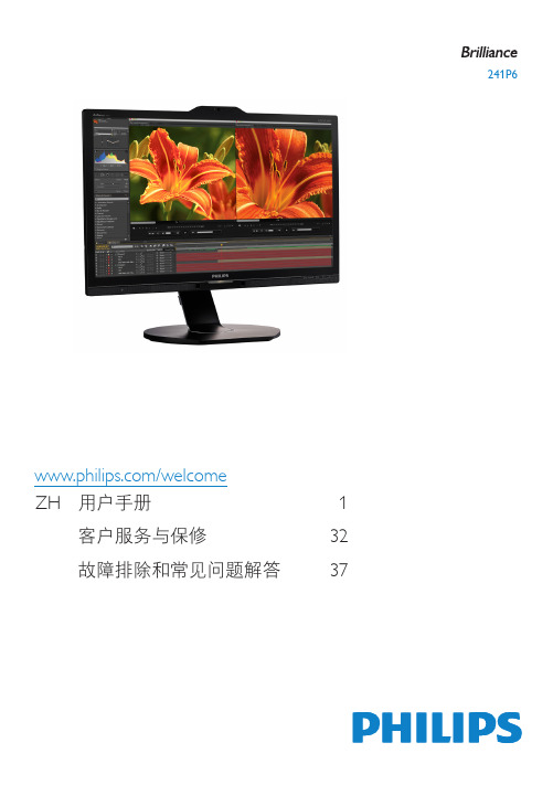
241P6/welcomeZH 用户手册 1客户服务与保修 32故障排除和常见问题解答 37目录1. 重要 (1)1.1 安全措施与维修 (1)1.2 标志说明 (2)1.3 产品和包装材料的废弃 (3)2. 设置显示器 (4)2.1 安装 (4)2.2 操作显示器 (6)2.3 MultiView (9)2.4 卸下底座装置 (12)2.5 MHL(Mobile High-Definition Link,移动高清链接)简介 (12)3. 图像优化 (14)3.1 SmartImage (14)3.2 SmartContrast (15)4. PowerSensor™ (16)5. LightSensor (17)6. 内置摄像头和麦克风 (18)6.1 PC系统要求 (18)6.2 使用此设备 (18)7. 技术规格 (19)7.1 分辨率和预设模式 (22)8. 电源管理 (23)9. 管制信息 (24)10. 客户服务与保修 (32)10.1 Philips平板显示器像素缺陷规定..3210.2 客户服务与保修 (34)11. 故障排除和常见问题解答 (37)11.1 故障检修 (37)11.2 一般常见问题解答 (38)11.3 MultiView常见问题解答 (40)1. 重要此电子版用户指南适合使用Philips显示器的所有用户。
请在使用您的显示器之前花点时间阅读本用户手册。
它包含与使用显示器相关的重要信息和注意事项。
产品享受Philips保修须符合下列条件:产品适当用于其设计目的、符合操作说明、返修时提供原始帐单或付款收据,帐单或收据应载明购货日期、销售商名称、产品型号及生产号。
1.1 安全措施与维修警告使用本文档中未介绍的控制、调整或过程可能导致碰撞、电气危险和/或机械危险。
连接和使用电脑显示器时,请阅读并遵循以下说明。
操作• 请使显示器远离阳光直接照射、明亮强光线、以及任何其他热源。
- 1、下载文档前请自行甄别文档内容的完整性,平台不提供额外的编辑、内容补充、找答案等附加服务。
- 2、"仅部分预览"的文档,不可在线预览部分如存在完整性等问题,可反馈申请退款(可完整预览的文档不适用该条件!)。
- 3、如文档侵犯您的权益,请联系客服反馈,我们会尽快为您处理(人工客服工作时间:9:00-18:30)。
S7-200 & S7-200 •配置主叫端
•配置被叫端
S7-200 & Micro/WIN •配置EM241 •配置Micro/WIN •连接
2
1
A&D Service and Support in China
EM241 快速入门
通讯选择
1. 点击Phone Numbers。 2. 点击New Phone Numbers输入 要与该PLC通讯的远程PLC所使 用的电话号码。
•配置被叫端
21-xXXx 或更新版本
S7-200 & Micro/WIN •配置EM241 •配置Micro/WIN •连接
• 两个EM241, 订货号为 6ES7 241-1AA22-0XA0 。
A&D Service and Support in China
EM241 快速入门
通讯选择
S7-200 & S7-200 •配置主叫端
A&D Service and Support in China
EM241 快速入门
通讯选择
S7-200 & S7-200 •配置主叫端
•配置被叫端
S7-200 & Micro/WIN •配置EM241 •配置Micro/WIN •连接
您可以使用向导程序为您提供的子程序,在Micro/WIN中编写图中的通讯程序。然后, 将整个项目下载到PLC中,并将PLC重新上电或者由STOP切换到RUN。
3. 点击Next>按钮。
A&D Service and Support in China
EM241 快速入门
通讯选择
S7-200 & S7-200 •配置主叫端
•配置被叫端
S7-200 & Micro/WIN •配置EM241 •配置Micro/WIN •连接
1 2 3 4 1. 在此选择模块是否要密码保护,选择密码保护后,任何人要通过EM241连 接到该PLC都必须提供密码。 2. 在此处填写密码。 3. 在此处确认密码。 4. 点击Next>按钮。
通讯选择
S7-200 & S7-200 •配置主叫端
•配置被叫端
S7-200 & Micro/WIN •配置EM241 •配置Micro/WIN •连接
1 2 1. 回拨功能只有在通过Micro/WIN对PLC进行远程编程时才起作用,在两个 PLC通过拨号进行数据传输时无效,且被拨叫的一方不能使用回拨功能。回 拨功能的使用参见S7-200与Micro/WIN的通讯 2. 点击Next 〉。
EM241 快速入门
通讯选择
S7-200 & S7-200 •配置主叫端
•配置被叫端
S7-200 & Micro/WIN •配置EM241 •配置Micro/WIN •连接
1 1. 配置好所需要的数据传输后点击Next 〉。
A&D Service and Support in China
EM241 快速入门
23
5
1
4
A&D Service and Support in China
EM241 快速入门
通讯选择
如果该PLC需要从远程PLC读/写数据 1. 选择Both a Data Read and a Data Write。 2. 在Define a Data Read下定义要 读取得数据。 3. 在Define a Data Write下定义要 写入的数据
A&D Service and Support in China
EM241 快速入门
通讯选择
S7-200 & S7-200 •配置主叫端
•配置被叫端
S7-200 & Micro/WIN •配置EM241 •配置Micro/WIN •连接
1 1. 在此处选择模块的位置。
2
3
2. 在线的情况下,您也可以用Read Modules按钮搜寻在线的EM241模块。
EM241 快速入门
通讯选择
当然了! 我们现在已经有EM241 调制解调器模块了!
S7-200 & S7-200 •配置主叫端
我能用S7-200连公共电话网吗?
•配置被叫端
S7-200 & Micro/WIN •配置EM241 •配置Micro/WIN •连接
您可以选择 EM241将S7-200连接在电话网上 !
S7-200 & S7-200 •配置主叫端
3. 在此输入对该电话号码的注释。 4. 在此输入电话号码。 5.如果使用这个电话号码的调制解 调器模块(EM241)使用了密码 保护,在此输入正确的密码。 6. 点击Save存储电话号码。
•配置被叫端
S7-200 & Micro/WIN •配置EM241 •配置Micro/WIN •连接
A&D Service and Support in China
EM241 快速入门
通讯选择
必备条件
• 带有STEP 7 Micro/WIN32软件的编程设备,软件版本 3.2 SP1以上。
S7-200 & S7-200 •配置主叫端
• PC/PPI 电缆或者 CP5611/5511/5411 和MPI电缆。 • 两个CPU22X,订货号6ES7 xxx-xxXX
S7-200 & S7-200 •配置主叫端
•配置被叫端
S7-200 & Micro/WIN •配置EM241 •配置Micro/WIN •连接
2
1
3
A&D Service and Support in China
EM241 快速入门
通讯选择
1. 如果该PLC要对多个不连续 的地址进行读/写,点击New Transfer建立相应的数据传输。 2. 要删除当前定义的数据传输, 点击Delete Transfer。
EM241 快速入门
通讯选择
S7-200 & S7-200 •配置主叫端
•配置被叫端
S7-200 & Micro/WIN •配置EM241 •配置Micro/WIN •连接
1 3 1. 选择Configure an EM241 Modem Module 2. 点击 Next 〉按钮
2
3.点击 Yes 编译当前程序
A&D Service and Support in China
EM241 快速门
通讯选择
S7-200 & S7-200 •配置主叫端
•配置被叫端
•配置被叫端
S7-200 & Micro/WIN •配置EM241 •配置Micro/WIN •连接
使用STEP 7 Micro/WIN32中的向导程序。软件的版本应该为V3.2 SP1或以上。在命令菜 单中选择Tools--> Modem Expansion Wizard。
A&D Service and Support in China
1
3
2
A&D Service and Support in China
EM241 快速入门
通讯选择
如果该PLC需要向远程PLC写数据 1. 选择Only a Data Write。
S7-200 & S7-200 •配置主叫端
2. 在此输入要向远程PLC写入的字 节长度。 3. 在此输入数据源的起始地址。 4. 在此输入数据目的地的起始 地址。 5. 在此为这个数据传输定义一个符 号名(符号名将在编程时使用,建 议使用英文并区分大小写)。
2. 在此输入要从远程PLC读取的 字节长度。 3. 在此输入数据目的地的起始 地址。 4. 在此输入数据源的起始地址。 5. 在此为这个数据传输定义一 个符号名(符号名将在编程时 使用,建议使用英文并区分大 小写) 。
•配置被叫端
S7-200 & Micro/WIN •配置EM241 •配置Micro/WIN •连接
3. 在程序中使用的号码必须有一 个符号名,在此为号码定义符号 名,符号名为英文且区分大小写。 4. 点击Save Symbol修改符号名。
•配置被叫端
S7-200 & Micro/WIN •配置EM241 •配置Micro/WIN •连接
3
1
4
2
A&D Service and Support in China
2
1
5
4
3
6
A&D Service and Support in China
EM241 快速入门
通讯选择
1. 框中列出所有可供使用的电话 号码,通过点击New Phone Number…向其中添加号码。
S7-200 & S7-200 •配置主叫端
2. 框中列出所有将在程序中使用 的电话号码,通过点击左边的两 个箭头添加或移除号码。
A&D Service and Support in China
EM241 快速入门
通讯选择
S7-200 & S7-200 •配置主叫端
•配置被叫端
S7-200 & Micro/WIN •配置EM241 •配置Micro/WIN •连接
2 1 1. 填写模块所占用的V存储区的起始地址。
3
2. 你也可以通过Suggest Address按钮来获得系统建议的V存储区的起始地址。 3. 点击Next>按钮。
EM241 快速入门
通讯选择
1. 点击Properties…能够对所有可 共使用的号码进行修改或删除。 2.点击 确定。
