FQI8N60C中文资料
8N60C PDF规格书

101
100
150℃
25℃
※ Notes :
1. VGS = 0V 2. 250μ s Pulse Test
10-1
0.2
0.4
0.6
0.8
1.0
1.2
1.4
VSD, Source-Drain voltage [V]
Figure 4. Body Diode Forward Voltage Variation with Source Current and Temperature
Thermal Resistance.Junction- to-Case
Maximum lead temperature for soldering purposes, 1/8" from case for 5 seconds
Junction Temperature Storage Temperature Range
Top :
VGS 15.0 V
10.0 V
8.0 V
101
7.0 V 6.0 V
5.5 V
5.0 V
Bottom : 4.5 V
ID, Drain Current [A]
100
※ Notes : 1. 250μ s Pulse Test
2. TC = 25℃
100
101
VDS, Drain-Source Voltage [V]
Figure 3. On-Resistance Variation vs Drain Current and Gate Voltage
2000 1500 1000
500
Ciss Coss
Crss
Ciss = Cgs + Cgd (Cds = shorted) Coss = Cds + Cgd Crss = Cgd
防盗报警器什么品牌好

广州艾礼富电子AL-6480C-BC报警系统是具有很强的实用性被广泛地应用在别墅小区及周界报警系统、以及办公大楼等各类大型安保系统可实现计算机软件管理、云服务报警系统相连、并方便地与其它系统集成。
以下是防盗报警器功能介绍。
一. 主要功能最多可以接1024个防区,通过外扩RS485扩展板或IP扩展模块可以外接最多128个防区扩展模块或主机,最多可以支持1024个扩展防区。
可最多接入8个键盘,独立操作,LCD显示。
各键盘分别对自己的所管辖的所有防区独立同时进行布防、撤防等操作。
通过主键盘可以编程,任意键盘可编程跟随所有报警并显示报警信息。
主机本身最多支持8个有线防区。
可外扩WiFi/IP模块、GPRS模块,通过RS232或IP实现与中心软件计算机连接。
通过WiFi/IP模块、GPRS模块实现和云服务报警系统连接。
外扩电话模块支持3组中心电话号码报警、8组用户号码报警、1组布防号码上报、1组撤防号码上报。
防区名称汉字任意更改,电脑配置,每个防区最多支持7个汉字。
挂在RS485扩展通讯总线上的设备都可以带有1-16个输出,其防区扩展模块最多带有1个输出,联动输出设备最多可带16个输出。
每个防区可联动最多8个输出。
联动包括:防区报警联动、防区布撤防联动、防区异常联动。
可以达到电子地图、DVR报警输入、就地报警等功能。
本机支持17组密码。
包括:1组安装密码、16组用户密码。
通过键盘密码、遥控器、中心软件、手机APP软件对键盘进行布撤防。
分别可以存储1000条的报警和操作纪录,掉电保存。
有20秒的电话报警语音,可以自己选择语音文件写入。
通过电脑进行编程和配置。
可远程配置好,文件发送,就地写入主机,让编程和服务更为简单、有效。
二.电性能指标输入电源DC12-27V主机板静态耗电300mA报警状态850mA报警输出口DC12V 1A外观尺寸335 x 275 x 80mm单个通讯端口总线总长度不得大于1200m为了保障您的权益,请通过正规渠道购买我们的产品,本产品通过3C认证专利保护,产品贴有防伪标签,包装印有微信二维码,方便提供技术支持。
WFF8N60(8n60)参数

Continuous drain reverse current Pulse drain reverse current Forward voltage(diode) Reverse recovery time Reverse recovery charge
Symbol
Unit
nA V µA µA V V Ω S
Drain cut -off current
IDSS VDS=480V,Tc=125℃
Drain -source breakdown voltage Gate threshold voltage Drain -source ON resistance Forward Transconductance Input capacitance Reverse transfer capacitance Output capacitance Turn-on Rise time Turn-on delay time Switching time Turn-off Fall time Turn-off delay time Total gate charge(gate-source
Symbol
IGSS V(BR)GSS
Test Condition
VGS=±30V,VDS=0V IG=±10 µA,VDS=0V VDS=600V,VGS=0V
Min
±30 600 2 -
Type
0.8 8.7 1380 23 115 80 30 85 125
Max
±100 10 100 4 1.2 1800 30 150 170 70
Copyright@Winsemi Microelectronics Co., Ltd., All right reserved.
8位机讲义

存储器结构
内部数据存储器
内部数据存储器被划分为物理上分开的两个不同的区域: 256B RAM和128B 特殊功能寄存器(SFR)区。RAM的 高128B和SFR区共用相同的地址段,通过不同的寻址方式 访问。RAM的低128B可通过直接寻址或寄存器间接寻址 方式访问;RAM的高128B只能通过寄存器间接寻址方式 访问;SFR只能通过直接寻址方式访问。RAM的地址段 20H到2FH的16个字节可位寻址;地址段30H到7FH可用作 暂存寄存器或堆栈。
存储器结构
程序存储器
使用一个专用接口使CPU和程序存储器直接 相连(而无需任何引脚连接),CPU的性能 得到优化。这意味着在每个时钟的上升沿均 能读取代码。因此,这里不存在“内部”或 “外 部”程序存储器的概念,因为所有的代码均 从 同一个程序存储器接口存取。
存储器结构
数据存储器
数据存储器由内部存储器和外部存储器组成。 数据存储器的“内部”和“外部”标记用来 区分寄 存器存储器和使用“MOVX”指令存取数据的 64 KB数据存储器。该外部标记并非暗指外部数 据存储器位于片外。
存储器结构
XC886/888的CPU可寻址以下五个地址空间:
12KB启动ROM(BootROM)程序存储器 256B内部RAM数据存储器 1.5KB XRAM存储器(XRAM可作为程序存储器或外部数 据存储器进行读写) 128B SFR区 24/32KB Flash程序存储器(Flash器件);或24/32KB ROM程序存储器,外加4KB Flash(ROM器件)
功能概述
法的十进制的调整和比较。逻辑运算包括与、 或、异或、补码和循环移位(右环移、左环 移、或4位环移(半字节交换))。ALU还包 括一个布尔处理机,可执行置位、清零、补 码、等于1跳转、等于0跳转、等于1跳转并清 零,送入/取自进位位的位操作。在任意可寻 址位(或该位补码)和进位标志之间,可执
FKN1N60SA资料

FKN1N60SA TRIAC (Silicon Bidirectional Thyristor)tmAugust 2006FKN1N60SATRIAC (Silicon Bidirectional Thyristor)Application Explanation•Switching mode power supply, light dimmer, electric flasher unit, hair drier •TV sets, stereo, refrigerator, washing machine•Electric blanket, solenoid driver, small motor control •Photo copier, electric toolAbsolute Maximum Ratings T a= 25°C unless otherwise notedThermal CharacteristicsNote1: Infinite cooling condition.Note2: JESD51-10 ( Test Borad: FR4 3.0”*4.5”*0.062”, Minimum land pad)SymbolParameterValueRatingUnitsV DRM V RRM Peak Repetitive Off-State Voltage Sine Wave 50 to 60Hz, Gate Open 600V I T (RMS) RMS On-State Current Commercial frequency, sine full wave 360° conduction, Tc= 70 ℃ 1.0A I TSMSurge On-State CurrentSinewave 1 full cycle, peak value, non-repetitive50Hz 9A 60Hz10A I 2t I 2t for FusingValue corresponding to 1 cycle of halfwave, surge on-state current, tp=8.4ms0.41A 2s P GM Peak Gate Power Dissipation 5W P G (AV) Average Gate Power Dissipation 0.1W V GM Peak Gate Voltage 5V I GM Peak Gate Current 1A T J Junction Temperature - 40 ~ 125°C T STGStorage Temperature- 40 ~ 125°CSymbolParameterValueUnitsR θJC Thermal Resistance, Junction to Case (note1)40°C/W R θJAThermal Resistance, Junction to Ambient (note2)160°C/W1321: T 12: Gate 3: T 21 2 3TO-92Commutation dv/dt testDevice Test Condition Commutating voltage and current waveforms(inductive load)FKN1N60SA 1. Junction TemperatureT J=125°C2. Rate of decay of on-statecommutating current (di/dt)C 3. Peak off-state voltageV D = 300V Supply VoltageMain CurrentMain VoltageTimeTimeTimeV D(dv/dt)C(di/dt)CPackage Marking and Ordering InformationDevice Marking Device Package Packing Tape Width Quantity K1N60SA FKN1N60SA TO-92Bulk----DISCLAIMERFAIRCHILD SEMICONDUCTOR RESERVES THE RIGHT TO MAKE CHANGES WITHOUT FURTHER NOTICE TO ANY PRODUCTS HEREIN TO IMPROVE RELIABILITY, FUNCTION OR DESIGN. FAIRCHILD DOES NOT ASSUME ANY LIABILITY ARISING OUT OF THE APPLICATION OR USE OF ANY PRODUCT OR CIRCUIT DESCRIBED HEREIN;NEITHER DOES IT CONVEY ANY LICENSE UNDER ITS PATENT RIGHTS, NOR THE RIGHTS OF OTHERS. THESE SPECIFICATIONS DO NOT EXPAND THE TERMS OF FAIRCHILD’S WORLDWIDE TERMS AND CONDITIONS, SPE-CIFICALLY THE WARRANTY THEREIN, WHICH COVERS THESE PRODUCTS.LIFE SUPPORT POLICYFAIRCHILD’S PRODUCTS ARE NOT AUTHORIZED FOR USE AS CRITICAL COMPONENTS IN LIFE SUPPORT DEVICES OR SYSTEMS WITHOUT THE EXPRESS WRITTEN APPROVAL OF FAIRCHILD SEMICONDUCTOR CORPORATION.As used herein:1. Life support devices or systems are devices or systems which, (a) are intended for surgical implant into the body, or (b) support or sustain life, or (c) whose failure to perform when properly used in accordance with instructions for use provided in the labeling, can be reasonably expected to result in significant injury to the user.2. A critical component is any component of a life support device or system whose failure to perform can be reasonably expected to cause the failure of the life support device or system, or to affect its safety or effectiveness.PRODUCT STATUS DEFINITIONSDefinition of TermsDatasheet Identification Product Status DefinitionAdvance Information Formative or In Design This datasheet contains the design specifications forproduct development. Specifications may change inany manner without notice.Preliminary First Production This datasheet contains preliminary data, andsupplementary data will be published at a later date.Fairchild Semiconductor reserves the right to makechanges at any time without notice in order to improvedesign.No Identification Needed Full Production This datasheet contains final specifications. FairchildSemiconductor reserves the right to make changes atany time without notice in order to improve design.Obsolete Not In Production This datasheet contains specifications on a productthat has been discontinued by Fairchild semiconductor.The datasheet is printed for reference information only.Rev. I20。
F8L10C 系列 LoRa 模块私有版本使用说明书
F8L10C 系列LoRa 模块私有版本使用说明书此说明书适用于下列型号产品:客户热线:400-8838-199电话:+86-592-6300320传真:+86-592-5912735网址:地址:厦门集美软件园三期A06栋11层F8L10C 系列私有版本使用说明书文档版本密级V1.0.0产品名称:F8L10C 系列LoRa 模块共30页型号产品类别F8L10C-00LU LoRa 模块国内版本,带IPEX 头天线接口F8L10C-00LN LoRa 模块国内版本,引脚天线接口F8L10C-00HU LoRa 模块国外版本,带IPEX 头天线接口F8L10C-00HNLoRa 模块国外版本,引脚天线接口文档修订记录日期版本说明作者2022-04-19V1.0.0初始版本WYL/CXF2/30著作权声明本文档所载的所有材料或内容受版权法的保护,所有版权由厦门四信通信科技有限公司拥有,但注明引用其他方的内容除外。
未经四信公司书面许可,任何人不得将本文档上的任何内容以任何方式进行复制、经销、翻印、连接、传送等任何商业目的的使用,但对于非商业目的的、个人使用的下载或打印(条件是不得修改,且须保留该材料中的版权说明或其他所有权的说明)除外。
商标声明Four-Faith 、四信、、、均系厦门四信通信科技有限公司注册商标,未经事先书面许可,任何人不得以任何方式使用四信名称及四信的商标、标记。
3/30目录第一章产品简介 (5)1.1概述 (5)1.2产品特点 (5)1.3产品图片 (6)第二章模块接口 (7)2.1模块引脚定义 (7)2.2UART接口 (10)2.3GPIO规格 (10)2.4极限参数 (10)2.5天线接口 (10)第三章模块封装 (12)3.1模块封装视图 (12)3.2推荐封装设计尺寸 (13)3.3Re-flow回流焊温度范围 (14)第四章模块接口操作 (15)4.1UART通讯模式 (15)4.1.1信号描述 (15)4.1.2硬件连接 (15)4.1.3通讯传输字节格式 (16)第五章参数配置 (18)5.1配置连接 (18)5.2参数配置方式介绍 (18)5.3参数详细介绍 (19)5.3.1LoRa网络参数 (20)5.3.2系统参数 (22)5.3.3串口参数 (25)第六章参考电路 (26)6.1供电参考电路 (26)6.2串口通讯参考电路 (27)6.3IO输入输出控制设计 (29)6.3.1控制LED灯 (29)6.3.2ADC采集参考电路 (29)6.4IO口保护电路 (30)4/30第一章产品简介1.1概述F8L10C系列LoRa数据传输模块是一种基于LoRa技术的嵌入式无线数据传输模块,采用LoRa网络为用户提供无线数据传输功能,同时兼容FSK*调制方式。
FQPF2N60C资料

100
150℃ 25℃
※ Notes :
1. 2.
2V5GS0μ=s0VPulse
Test
10-1
0.2
0.4
0.6
0.8
1.0
1.2
1.4
VSD, Source-Drain voltage [V]
Figure 4. Body Diode Forward Voltage Variation with Source Current and Temperature
VGS = 0 V, IS = 2 A,
-- 230
--
ns
Qrr
Reverse Recovery Charge
dIF / dt = 100 A/µs
(Note 4) --
1.0
--
µC
Notes:
1. Repetitive Rating : Pulse width limited by maximum junction temperature
Parameter Thermal Resistance, Junction-to-Case Thermal Resistance, Case-to-Sink Typ. Thermal Resistance, Junction-to-Ambient
FQP2N60C 2.32 0.5 62.5
FQPF2N60C 5.5 -62.5
元器件交易网
FQP2N60C/FQPF2N60C
FQP2N60C/FQPF2N60C
600V N-Channel MOSFET
QFET TM
General Description
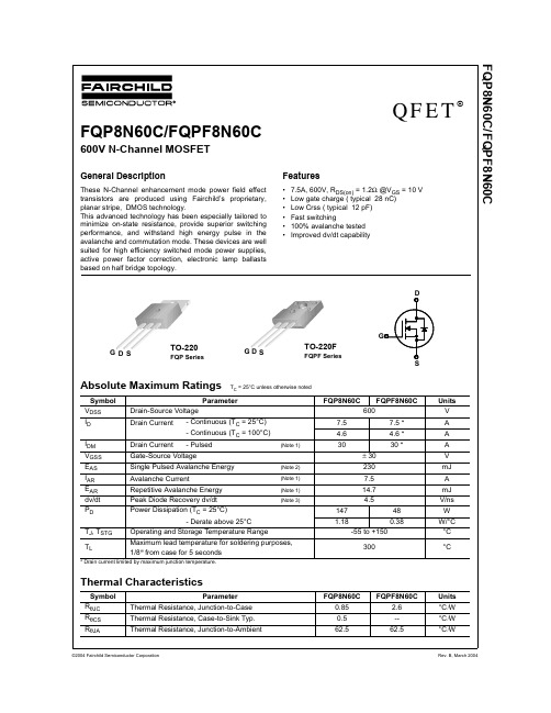
These N-Channel enhancement mode power field effect transistors are produced using Fairchild’s proprietary, planar stripe, DMOS technology. This advanced technology has been especially tailored to minimize on-state resistance, provide superior switching performance, and withstand high energy pulse in the avalanche and commutation mode. These devices are well suited for high efficiency switched mode power supplies, active power factor correction, electronic lamp ballasts based on half bridge topology.
N80C196KB资料

Port 3 and Port 4 External Memory 232 Bytes Register RAM (Note 1) CPU SFR’s (Notes 1 3)
Figure 2 The 8XC196KB Nomenclature Table 1 Thermal Characteristics Package Type PLCC QFP ija 35 C W 70 C W ijc 13 C W 4C W
All thermal impedance data is approximate for static air conditions at 1W of power dissipation Values will change depending on operation conditions and application See the Intel Packaging Handbook (order number 240800) for a description of Intel’s thermal impedance test methodology
270909 – 2
Address 0FFFFH 04000H 3FFFH 2080H 207FH 2040H 203FH 2030H 202FH 2020H 201FH 201AH 2019H 2018H 2017H 2014H 2013H 2000H 1FFFH 1FFEH 1FFDH 0100H 00FFH 0018H 0017H 0000H
Y
Dynamically Configurable 8-Bit or 16-Bit Buswidth Full Duplex Serial Port High Speed I O Subsystem 16-Bit Timer 16-Bit Up Down Counter with Capture Pulse-Width-Modulated Output Four 16-Bit Software Timers 10-Bit A D Converter with Sample Hold HOLD HLDA Bus Protocol Extended Temperature AY Y
FQP8N60C资料
V
V/°C
µA µA nA nA
On Characteristics
VGS(th) Gate Threshold Voltage
RDS(on)
Static Drain-Source On-Resistance
gFS
Forward Transconductance
VDS = VGS, ID = 250 µA
600 --
∆BVDSS Breakdown Voltage Temperature / ∆TJ Coefficient
ID = 250 µA, Referenced to 25°C --
0.7
IDSS
Zero Gate Voltage Drain Current
VDS = 600 V, VGS = 0 V VDS = 480 V, TC = 125°C
Figure 1. On-Region Characteristics
3.5
3.0
2.5
VGS = 10V
2.0
1.5
VGS = 20V
1.0 ※ Note : TJ = 25℃
0.5 0
5
10
15
20
ID, Drain Current [A]
Figure 3. On-Resistance Variation vs Drain Current and Gate Voltage
VDS = 480V 6
4
2
※ Note : ID = 8A
0
0
5
10
Symbol
Parameter
TC = 25°C unless otherwise noted
Test Conditions
8N60中文资料
VDS = 25 V, VGS = 0 V, f = 1MHz
965 1255 105 135 12 16 16.5 45 60.5 130 81 170 64.5 140 28 36 4.5 12
VDD = 300V, ID = 7.5 A, RG = 25Ω (Note 4, 5)
VDS= 480V,ID= 7.5A, VGS= 10 V (Note 4, 5)
PARAMETER SYMBOL 8N60-A 8N60-B
Power MOSFET
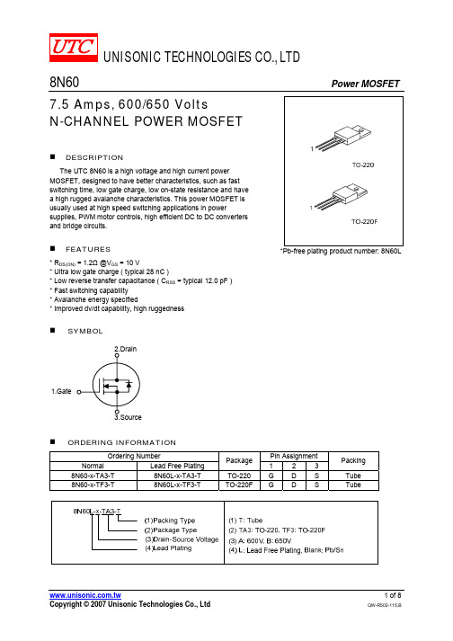
RATINGS UNIT 600 V Drain-Source Voltage VDSS 650 V Gate-Source Voltage VGSS ±30 V Avalanche Current (Note 1) IAR 7.5 A TC = 25°C 7.5 A Continuous Drain Current ID TC = 100°C 4.6 A Pulsed Drain Current (Note 1) IDM 30 A Single Pulsed (Note 2) EAS 230 mJ Avalanche Energy 14.7 mJ Repetitive (Note 1) EAR Peak Diode Recovery dv/dt (Note 3) dv/dt 4.5 V/ns TO-220 147 W Power Dissipation PD TO-220F 48 W Junction Temperature TJ +150 Operating Temperature TOPR -55 ~ +150 Storage Temperature TSTG -55 ~ +150 Note: Absolute maximum ratings are those values beyond which the device could be permanently damaged. Absolute maximum ratings are stress ratings only and functional device operation is not implied.
550C中文资料
550C中文资料关键信息项:1、资料名称:550C 中文资料2、资料用途:____________________________3、资料提供方:____________________________4、资料接收方:____________________________5、资料使用期限:____________________________6、资料保密要求:____________________________7、违约责任:____________________________8、争议解决方式:____________________________11 协议背景本协议旨在规范550C 中文资料的相关事宜,确保资料的合理使用、保护和传播。
111 资料的定义和范围本协议中所提及的550C 中文资料包括但不限于文字、图表、图像、音频、视频等与 550C 相关的各类中文形式的信息。
112 资料的用途资料接收方应仅将 550C 中文资料用于具体合法且明确的用途,不得用于其他任何未经授权的目的。
12 资料提供方的权利和义务121 提供方应确保所提供的 550C 中文资料的真实性、准确性和完整性。
122 提供方有权对资料接收方的使用情况进行监督和检查。
13 资料接收方的权利和义务131 接收方应按照协议约定的用途使用 550C 中文资料。
132 接收方有义务对资料进行妥善保管,采取合理的安全措施防止资料泄露、丢失或损坏。
133 未经提供方书面同意,接收方不得将资料转让、出售、出租或提供给任何第三方。
14 资料使用期限141 双方约定 550C 中文资料的使用期限为具体时间段。
142 在使用期限届满后,接收方应立即停止使用并按照提供方的要求归还或销毁资料。
15 资料保密要求151 接收方应对 550C 中文资料予以保密,不得向任何无关人员透露资料的内容。
152 接收方应采取必要的保密措施,如限制访问、加密存储等,以确保资料的保密性。
FQPF4N60C
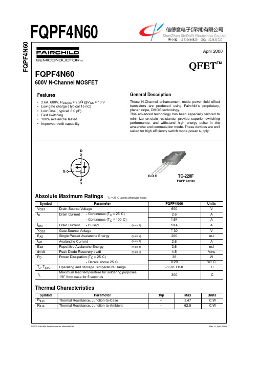
3.0 ---
-1.77 3.1
5.0 2.2 --
V Ω S
Dynamic Characteristics
Ciss Coss Crss Input Capacitance Output Capacitance Reverse Transfer Capacitance VDS = 25 V, VGS = 0 V, f = 1.0 MHz ---520 70 8 670 90 11 pF pF pF
Thermal Characteristics
Symbol RθJC RθJA Parameter Thermal Resistance, Junction-to-Case Thermal Resistance, Junction-to-Ambient Typ --Max 3.47 62.5 Units °CW °CW
6
9
12
15
VDS, Drain-Source Voltage [V]
QG, Total Gate Charge [nC]
Figure 5. Capacitance Characteristics
Figure 6. Gate Charge Characteristics
©2000 Fairchild Semiconductor International
10
-1
2Leabharlann 46810
10
-1
10
0
10
1
VGS , Gate-Source Voltage [V]
VDS , Drain-Source Voltage [V]
Figure 2. Transfer Characteristics
FQP12N60C中文资料

©2003 Fairchild Semiconductor Corporation
Rev. B, October 2003
元器件交易网
FQP12N60C/FQPF12N60C
Typical Characteristics
V Top : 15.0GSV
10.0 V 8.0 V 7.0 V 6.0 V 5.5 V 5.0 V 101 Bottom : 4.5 V
(Note 2)
IAR
Avalanche Current
(Note 1)
EAR
Repetitive Avalanche Energy
(Note 1)
dv/dt
Peak Diode Recovery dv/dt
(Note 3)
PD
Power Dissipation (TC = 25°C)
- Derate above 25°C
Figure 5. Capacitance Characteristics
Capacitance [pF]
©2003 Fairchild Semiconductor Corporation
VGS, Gate-Source Voltage [V]
IDR, Reverse Drain Current [A]
2.0 --
4.0
V
VGS = 10 V, ID = 6 A
-- 0.53 0.65
Ω
VDS = 40 V, ID = 6 A
(Note 4) --
13
--
S
Dynamic Characteristics
Ciss
Input Capacitance
Coss
IXKK85N60CSN中文资料

4V
6
7
-50
-25
0
25
50
75
100
125
150
V D S - Volts Fig. 5. RDS(on) Norm alized to ID100 Value vs. ID
4 3.7 3.4 VGS = 10V 100 90 80 TJ = 125ºC 70
TJ - Degrees Centigrade Fig. 6. Drain Current vs. Case Tem perature
4 BACK SIDE
1 - GATE 2, 4 - DRAIN (COLLECTOR) 3 - SOURCE (EMITTER)
NOTE: 1. This drawing meets all dimensions requirement of JEDEC outlines TO-264AAexcept L, L1, L2, L3. 2. All metal surface are solder plated except trimmed area.
tp = 300μs
R D S (on) - Normalized
3.1 2.8 2.5 2.2 1.9 1.6 1.3 1 0.7 0 40 80 120 160
I D - Amperes
TJ = 25ºC
60 50 40 30 20 10 0
200
240
280
320
360
-50
-25
0
25
50
75
CoolMOS™ is a trademark of Infineon Technologies AG.
VGS = 10 V; VDS = 380 V ID = 60 A; RG = 2.2 Ω
FAIRCHILD FQP8N60C FQPF8N60C 数据手册

现货库存、技术资料、百科信息、热点资讯,精彩尽在鼎好!FQP8N60C/FQPF8N60CNotes:1. Repetitive Rating : Pulse width limited by maximum junction temperature2. L = 7.3mH, I AS = 7.5 A, V DD = 50V, R G = 25 Ω, Starting T J = 25°C3. I SD ≤ 7.5A, di/dt ≤ 200A/µs, V DD ≤ BV DSS, Starting T J = 25°C4. Pulse Test : Pulse width ≤ 300µs, Duty cycle ≤ 2%5. Essentially independent of operating temperatureOn CharacteristicsV GS(th)Gate Threshold Voltage V DS = V GS , I D = 250 µA 2.0-- 4.0V R DS(on)Static Drain-Source On-ResistanceV GS = 10 V, I D = 3.75 A-- 1.0 1.2Ωg FSForward TransconductanceV DS = 40 V, I D = 3.75 A (Note 4)--8.7--SDynamic CharacteristicsC iss Input Capacitance V DS = 25 V, V GS = 0 V, f = 1.0 MHz--9651255pF C oss Output Capacitance--105135pF C rssReverse Transfer Capacitance--1216pFSwitching Characteristicst d(on)Turn-On Delay Time V DD = 300 V, I D = 7.5A,R G = 25 Ω(Note 4, 5)--16.545ns t r Turn-On Rise Time --60.5130ns t d(off)Turn-Off Delay Time --81170ns t f Turn-Off Fall Time --64.5140ns Q g Total Gate Charge V DS = 480 V, I D = 7.5A,V GS = 10 V(Note 4, 5)--2836nC Q gs Gate-Source Charge -- 4.5--nC Q gdGate-Drain Charge--12--nCDrain-Source Diode Characteristics and Maximum RatingsI S Maximum Continuous Drain-Source Diode Forward Current ----7.5A I SM Maximum Pulsed Drain-Source Diode Forward Current----30A V SD Drain-Source Diode Forward Voltage V GS = 0 V, I S = 7.5 A ---- 1.4V t rr Reverse Recovery Time V GS = 0 V, I S = 7.5 A,dI F / dt = 100 A/µs (Note 4)--365--ns Q rrReverse Recovery Charge-- 3.4--µCFQP8N60C/FQPF8N60CDISCLAIMERFAIRCHILD SEMICONDUCTOR RESERVES THE RIGHT TO MAKE CHANGES WITHOUT FURTHER NOTICE TO ANY PRODUCTS HEREIN TO IMPROVE RELIABILITY, FUNCTION OR DESIGN. FAIRCHILD DOES NOT ASSUME ANY LIABILITY ARISING OUT OF THE APPLICATION OR USE OF ANY PRODUCT OR CIRCUIT DESCRIBED HEREIN;NEITHER DOES IT CONVEY ANY LICENSE UNDER ITS PATENT RIGHTS, NOR THE RIGHTS OF OTHERS.LIFE SUPPORT POLICYFAIRCHILD’S PRODUCTS ARE NOT AUTHORIZED FOR USE AS CRITICAL COMPONENTS IN LIFE SUPPORT DEVICES OR SYSTEMS WITHOUT THE EXPRESS WRITTEN APPROVAL OF FAIRCHILD SEMICONDUCTOR CORPORATION.As used herein:1. Life support devices or systems are devices or systems which, (a) are intended for surgical implant into the body,or (b) support or sustain life, or (c) whose failure to perform when properly used in accordance with instructions for use provided in the labeling, can be reasonably expected to result in significant injury to the user.2. A critical component is any component of a life support device or system whose failure to perform can be reasonably expected to cause the failure of the life support device or system, or to affect its safety or effectiveness.PRODUCT STATUS DEFINITIONS Definition of TermsDatasheet Identification Product Status DefinitionAdvance InformationFormative or In Design This datasheet contains the design specifications for product development. Specifications may change in any manner without notice.PreliminaryFirst ProductionThis datasheet contains preliminary data, andsupplementary data will be published at a later date.Fairchild Semiconductor reserves the right to make changes at any time without notice in order to improve design.No Identification Needed Full ProductionThis datasheet contains final specifications. Fairchild Semiconductor reserves the right to make changes at any time without notice in order to improve design.Obsolete Not In ProductionThis datasheet contains specifications on a product that has been discontinued by Fairchild semiconductor.The datasheet is printed for reference information only.TRADEMARKSThe following are registered and unregistered trademarks Fairchild Semiconductor owns or is authorized to use and is not intended to be an exhaustive list of all such trademarks.FACT Quiet series™FAST ®FASTr™FPS™FRFET™GlobalOptoisolator™GTO™HiSeC™I 2C™ImpliedDisconnect™ISOPLANAR™LittleFET™MICROCOUPLER™MicroFET™MicroPak™MICROWIRE™MSX™MSXPro™OCX™OCXPro™OPTOLOGIC ®OPTOPLANAR™PACMAN™POP™Power247™PowerSaver™PowerTrench ®QFET™QS™QT Optoelectronics™Quiet Series™RapidConfigure™RapidConnect™SILENT SWITCHER ®SMART START™SPM™Stealth™SuperFET™SuperSOT™-3SuperSOT™-6SuperSOT™-8SyncFET™TinyLogic ®TINYOPTO™TruTranslation™UHC™UltraFET ®VCX™ACEx™ActiveArray™Bottomless™CoolFET™CROSSVOLT ™DOME™EcoSPARK™E 2CMOS™EnSigna™FACT™Across the board. Around the world.™The Power Franchise ®Programmable Active Droop™。
富士通高密度连接器FCN-360系列数据表说明书

s FEATURES•Many applicationsVarious connectors are available for connection by means of soldering, wire wrapping, crimping, PC board mounting, and insulation displacement connection (IDC). The user can choose a plug and jack combination that best meet each application.•Small size for high-density mountingThe connectors are small with a contact and terminal pitch of 2.54 mm (0.100 in.) between pins and between rows and are thus well suited for high-density mounting.•Sturdy shell guideSturdy shell guides are used to prevent mismating and to protect the pins.•Excellent cost performanceStreamlined design and automated manufacturing,including use of partial solder plating, provide excellent cost performance.s SPECIFICATIONSs MATERIALSRECTANGULAR CONNECTORSFCN-360 SERIESItemOperating temperature range Current Rating Voltage Rating Contact resistance Insulation resistance Dielectric withstanding voltage Insertion force Withdrawal forceApplicable wireApplicable PC boardSpecification–55°C to +85°C DC 3A (IDC type: 1 A)AC 250V15 m Ω max. (DC 6 V, 0.3 A)1000 M Ω min. (DC 500 V)AC 500 V for 1 minute2.5 kg max. (8 contacts), 20 kg max. (64 contacts)0.3 kg min. (8 contacts), 2.3 kg min. (64 contacts)φ0.60 mm (0.024 in.) max, AWG #23 or less φ0.32 mm (0.013 in.) to φ0.26 mm (0.010 in.), AWG #28 to #30Standard contacts φ0.51 mm (0.020 in.) to φ0.32 mm (0.013in.), AWG #24 to #28, insulator φ1.2 mm (0.047 in.) max.Contacts for thick wires φ0.64 mm (0.025 in.) to φ0.32 mm (0.013 in.), AWG #22 to #28, insulator φ1.7 (0.067 in.) max.Flat cable 1.27 mm (0.050 in.) pitch, AWG #28 (stranded wire),AWG #30 (solid wire)1.6 mm (0.063 in.) standard thickSoldering Wire-wrappingCrimpingIDCItem Insulator Conductor PlatingMaterialPolyester (363J: PC94V-2)Copper alloyGold plating, silver platingNot for New DesignACCESSORIESs MOUNTING SYLENote:When the jack or plug without a cover (shaded part) is used, have M2.6 × 8 mm machine screws ready inorder to tighten the connector.s SHAPES AND DIMENSIONS OF METAL FITTINGS1.Straight Mounting Metal Fittings2.Right-angle Mounting Metal Fittings3.Straight Mounting Round Metal Fittings© 2001 Fujitsu Components America, Inc. All company and product names are trademarks or registered trademarks of their respective owners. Rev. 09/2001JapanFujitsu Component Limited Gotanda-Chuo Building3-5, Higashigotanda 2-chome, Shinagawa-ku Tokyo 141, Japan Tel: (81-3) 5449-7010Fax: (81-3) 5449-2626Email:************** Web: North and South AmericaFujitsu Components America, Inc.250 E. Caribbean DriveSunnyvale, CA 94089 U.S.A.Tel: (1-408) 745-4900Fax: (1-408) 745-4970Email:*******************.com Web: EuropeFujitsu Components Europe B.V.Diamantlaan 252132 WV Hoofddorp NetherlandsTel: (31-23) 5560910Fax: (31-23) 5560950Email:***************************.com Web: Asia PacificFujitsu Components Asia Ltd.102E Pasir Panjang Road#04-01 Citilink Warehouse Complex Singapore 118529Tel: (65) 375-8560Fax: (65) 273-3021Email:*****************.com Fujitsu Components International Headquarter Offices。
FPGA可编程逻辑器件芯片EP3CLS150F780I6N中文规格书

1
On-chip parallel termination with calibration is only supported for input pins.
For more information on on-chip termination supported by Stratix II devices, refer to the Selectable I/O Standards in Stratix II & Stratix II GX Devices chapter in volume 2 of the Stratix II Device Handbook or the Stratix II GX Device Handbook.
Stratix II Architecture
f
For more information on tolerance specifications for on-chip termination with calibration, refer to the DC & Switching Characteristics chapter in volume 1 of the Stratix II Device Handbook.
f f
On-Chip Parallel Termination with Calibration
Stratix II devices support on-chip parallel termination with calibration for column I/O pins only. There is one calibration circuit for the top I/O banks and one circuit for the bottom I/O banks. Each on-chip parallel termination calibration circuit compares the total impedance of each I/O buffer to the external 50-Ω resistors connected to the RUP and RDN pins and dynamically enables or disables the transistors until they match. Calibration occurs at the end of device configuration. Once the calibration circuit finds the correct impedance, it powers down and stops changing the characteristics of the drivers.
- 1、下载文档前请自行甄别文档内容的完整性,平台不提供额外的编辑、内容补充、找答案等附加服务。
- 2、"仅部分预览"的文档,不可在线预览部分如存在完整性等问题,可反馈申请退款(可完整预览的文档不适用该条件!)。
- 3、如文档侵犯您的权益,请联系客服反馈,我们会尽快为您处理(人工客服工作时间:9:00-18:30)。
Notes:1. Repetitive Rating : Pulse width limited by maximum junction temperature2. L = 7.3mH, I AS = 7.5 A, V DD = 50V, R G = 25 Ω, Starting T J = 25°C3. I SD ≤ 7.5A, di/dt ≤ 200A/µs, V DD ≤ BV DSS, Starting T J = 25°C4. Pulse Test : Pulse width ≤ 300µs, Duty cycle ≤ 2%5. Essentially independent of operating temperatureOn CharacteristicsV GS(th)Gate Threshold Voltage V DS = V GS , I D = 250 µA 2.0-- 4.0V R DS(on)Static Drain-Source On-ResistanceV GS = 10 V, I D = 3.75 A-- 1.0 1.2Ωg FSForward TransconductanceV DS = 40 V, I D = 3.75 A (Note 4)--8.7--SDynamic CharacteristicsC iss Input Capacitance V DS = 25 V, V GS = 0 V, f = 1.0 MHz--9651255pF C oss Output Capacitance--105135pF C rssReverse Transfer Capacitance--1216pFSwitching Characteristicst d(on)Turn-On Delay Time V DD = 300 V, I D = 7.5A,R G = 25 Ω(Note 4, 5)--16.545ns t r Turn-On Rise Time --60.5130ns t d(off)Turn-Off Delay Time --81170ns t f Turn-Off Fall Time --64.5140ns Q g Total Gate Charge V DS = 480 V, I D = 7.5A,V GS = 10 V(Note 4, 5)--2836nC Q gs Gate-Source Charge -- 4.5--nC Q gdGate-Drain Charge--12--nCDrain-Source Diode Characteristics and Maximum RatingsI S Maximum Continuous Drain-Source Diode Forward Current ----7.5A I SM Maximum Pulsed Drain-Source Diode Forward Current----30A V SD Drain-Source Diode Forward Voltage V GS = 0 V, I S = 7.5 A ---- 1.4V t rr Reverse Recovery Time V GS = 0 V, I S = 7.5 A,dI F / dt = 100 A/µs (Note 4)--365--ns Q rrReverse Recovery Charge-- 3.4--µCFQB8N60C / FQI8N60CFQB8N60C / FQI8N60CDISCLAIMERFAIRCHILD SEMICONDUCTOR RESERVES THE RIGHT TO MAKE CHANGES WITHOUT FURTHER NOTICE TO ANY PRODUCTS HEREIN TO IMPROVE RELIABILITY, FUNCTION OR DESIGN. FAIRCHILD DOES NOT ASSUME ANY LIABILITY ARISING OUT OF THE APPLICATION OR USE OF ANY PRODUCT OR CIRCUIT DESCRIBED HEREIN;NEITHER DOES IT CONVEY ANY LICENSE UNDER ITS PATENT RIGHTS, NOR THE RIGHTS OF OTHERS.LIFE SUPPORT POLICYFAIRCHILD’S PRODUCTS ARE NOT AUTHORIZED FOR USE AS CRITICAL COMPONENTS IN LIFE SUPPORT DEVICES OR SYSTEMS WITHOUT THE EXPRESS WRITTEN APPROVAL OF FAIRCHILD SEMICONDUCTOR CORPORATION.As used herein:1. Life support devices or systems are devices or systems which, (a) are intended for surgical implant into the body,or (b) support or sustain life, or (c) whose failure to perform when properly used in accordance with instructions for use provided in the labeling, can be reasonably expected to result in significant injury to the user.2. A critical component is any component of a life support device or system whose failure to perform can be reasonably expected to cause the failure of the life support device or system, or to affect its safety or effectiveness.PRODUCT STATUS DEFINITIONS Definition of TermsDatasheet Identification Product Status DefinitionAdvance InformationFormative or In Design This datasheet contains the design specifications for product development. Specifications may change in any manner without notice.PreliminaryFirst ProductionThis datasheet contains preliminary data, andsupplementary data will be published at a later date.Fairchild Semiconductor reserves the right to make changes at any time without notice in order to improve design.No Identification Needed Full ProductionThis datasheet contains final specifications. Fairchild Semiconductor reserves the right to make changes at any time without notice in order to improve design.Obsolete Not In ProductionThis datasheet contains specifications on a product that has been discontinued by Fairchild semiconductor.The datasheet is printed for reference information only.TRADEMARKSThe following are registered and unregistered trademarks Fairchild Semiconductor owns or is authorized to use and is not intended to be an exhaustive list of all such trademarks.FACT Quiet Series™FAST ®FASTr™FRFET™GlobalOptoisolator™GTO™HiSeC™I 2C™ImpliedDisconnect™ISOPLANAR™LittleFET™MICROCOUPLER™MicroFET™MicroPak™MICROWIRE™MSX™MSXPro™OCX™OCXPro™OPTOLOGIC ®OPTOPLANAR™PACMAN™POP™Power247™PowerTrench ®QFET ®QS™QT Optoelectronics™Quiet Series™RapidConfigure™RapidConnect™SILENT SWITCHER ®SMART START™SPM™Stealth™SuperSOT™-3SuperSOT™-6SuperSOT™-8SyncFET™TinyLogic ®TINYOPTO™TruTranslation™UHC™UltraFET ®VCX™ACEx™ActiveArray™Bottomless™CoolFET™CROSSVOLT ™DOME™EcoSPARK™E2CMOS™EnSigna™FACT™Across the board. Around the world.™The Power Franchise™Programmable Active Droop™。
