MMSZ4688-F中文资料
MAX4688中文资料
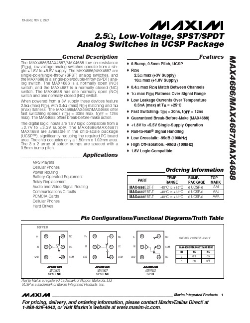
General DescriptionThe MAX4686/MAX4687/MAX4688 low on-resistance (R ON ), low-voltage analog switches operate from a sin-gle +1.8V to +5.5V supply. The MAX4686/MAX4687 are single-pole/single-throw (SPST) analog switches, and the MAX4688 is a single-pole/double-throw (SPDT) ana-log switch. The MAX4686 is a normally open (NO)switch, and the MAX4687 is a normally closed (NC)switch. The MAX4688 has one normally open (NO)switch and one normally closed (NC) switch.When powered from a 3V supply these devices feature 2.5Ω(max) R ON , with 0.4Ω(max) R ON matching and 1Ω(max) flatness. The MAX4686/MAX4687/MAX4688 offer fast switching speeds (t ON = 30ns max, t OFF = 12ns max). The MAX4688 offers break-before-make action.The digital logic inputs are 1.8V logic compatible from a +2.7V to +3.3V supply. The MAX4686/MAX4687/MAX4688 are available in the chip-scale package (UCSP™), significantly reducing the required PC board area. The chip occupies only a 1.50mm x 1.02mm area.The 3 x 2 array of solder bumps are spaced with a 0.5mm bump pitch.________________________ApplicationsMP3 Players Cellular Phones Power RoutingBattery-Operated Equipment Relay ReplacementAudio and Video Signal Routing Communications Circuits PCMCIA Cards Cellular Phones Hard DrivesFeatureso 6-Bump, 0.5mm Pitch, UCSP o R ON2.5Ωmax (+3V Supply)10Ωmax (+1.8V Supply)o 0.4Ωmax R ON Match Between Channels o 1Ωmax R ON Flatness Over Signal Range o Low Leakage Currents Over Temperature0.5nA (max) at T A = +25°C o Fast Switching: t ON = 30ns, t OFF = 12ns o Guaranteed Break-Before-Make (MAX4688)o +1.8V to +5.5V Single-Supply Operation o Rail-to-Rail ®Signal Handling o Low Crosstalk: -95dB (100kHz)o High Off-Isolation: -90dB (100kHz)o 1.8V Logic CompatibleMAX4686/MAX4687/MAX46882.5Ω, Low-Voltage, SPST/SPDT Analog Switches in UCSP Package________________________________________________________________Maxim Integrated Products1Pin Configurations/Functional Diagrams/Truth Table19-2042; Rev 1; 2/03Ordering InformationUCSP is a trademark of Maxim Integrated Products, Inc.For pricing, delivery, and ordering information,please contact Maxim/Dallas Direct!at 1-888-629-4642, or visit Maxim’s website at .M A X 4686/M A X 4687/M A X 46882.5Ω, Low-Voltage, SPST/SPDT Analog Switches in UCSP PackageABSOLUTE MAXIMUM RATINGSELECTRICAL CHARACTERISTICS(V+ = +2.7V to +3.3V, V IH = +1.4V, V IL = 0.5V, T A = T MIN to T MAX , unless otherwise noted. Typical values are at 3V and T A = +25°C.)(Notes 3, 4)Stresses beyond those listed under “Absolute Maximum Ratings” may cause permanent damage to the device. These are stress ratings only, and functional operation of the device at these or any other conditions beyond those indicated in the operational sections of the specifications is not implied. Exposure to absolute maximum rating conditions for extended periods may affect device reliability.All Voltages Referenced to GNDV+, IN .......................................................................-0.3V to +6V COM, NO, NC (Note1)..................................-0.3V to (V+ + 0.3V)Continuous Current NO, NC, COM ................................±100mA Peak Current NO, NC, COM(pulsed at 1ms, 10% duty cycle) ...............................±200mAContinuous Power Dissipation (T A = +70°C)3 x 2 UCSP (derate 10.1mW/°C at +70°C)..................808mW Operating Temperature Range ...........................-40°C to +85°C Storage Temperature Range ............................-65°C to +150°C Bump Reflow Temperature .............................................+235°CNote 1:Signals on NO, NC, and COM exceeding V+ are clamped by an internal diode. Limit forward-diode current to maximum cur-rent rating.Note 2:This device is constructed using a unique set of packaging techniques that impose a limit on the thermal profile the devicecan be exposed to during board level solder attach and rework. This limit permits only the use of the solder profiles recom-mended in the industry standard specification, JEDEC 020A, paragraph 7.6, Table 3 for IR/VPR and convection reflow.Preheating is requied. Hand or wave soldering is not allowed.MAX4686/MAX4687/MAX46882.5Ω, Low-Voltage, SPST/SPDT Analog Switches in UCSP Package_______________________________________________________________________________________3Note 4:UCSP parts are 100% tested at +25°C only and guaranteed by correlation at the full hot-rated temperature.Note 5:∆R ON = R ON(MAX ) - R ON(MIN), between switches.Note 6:Flatness is defined as the difference between the maximum and minimum value of on-resistance as measured over thespecified analog signal ranges.Note 7:Guaranteed by design.Note 8:Off Isolation = 20log 10(V COM / V NO ), V COM = output, V NO = input to off switch.Note 9:Between switches.ELECTRICAL CHARACTERISTICS (continued)(V+ = +2.7V to +3.3V, V IH = +1.4V, V IL = 0.5V, T A = T MIN to T MAX , unless otherwise noted. Typical values are at 3V and T A = +25°C.)(Notes 3, 4)M A X 4686/M A X 4687/M A X 46882.5Ω, Low-Voltage, SPST/SPDT Analog Switches in UCSP Package 4_______________________________________________________________________________________631291518-4010-15356085TURN-ON/OFF TIME vs. TEMPERATURETEMPERATURE (°C)t O N /O F F (n s )10001001010.1-4010-15356085ON/OFF-LEAKAGE CURRENTvs. TEMPERATURETEMPERATURE (°C)O N /O F F -L E A K A G E C U R R E N T (p A )806040200021345CHARGE INJECTION vs. V COMV COM (V)Q (p C )0428610120231456SUPPLY CURRENT vs. SUPPLY VOLTAGEM A X 4686/7/8 t o c 01SUPPLY VOLTAGE (V)S U P P L Y C U R R E N T (p A )1.02.01.53.02.53.54.0021345ON-RESISTANCE vs. V COMV COM (V)R O N (Ω)0.51.02.01.52.53.01.00.51.52.02.53.0ON-RESISTANCE vs. V COM (V+ = +3V)V COM (V)R O N (Ω)0.51.10.90.71.31.51.71.92.12.32.521345ON-RESISTANCE vs. V COM (V+ = +5V)V COM (V)R O N (Ω)00.51.01.52.01.52.53.54.52.03.04.05.05.5LOGIC THRESHOLD VOLTAGE vs. SUPPLY VOLTAGEV+ (V)L O G I C T H R E S H O L D V O L T A G E (V )01052015302535132456TURN-ON/OFF TIME vs. SUPPLY VOLTAGEV+ (V)t O N /O F F (n s )Typical Operating Characteristics(T A = +25°C, unless otherwise noted.)Applications InformationLogic InputsWhere the MAX4686/MAX4687/MAX4688 have a +3.3V supply, IN may be driven low to GND and driven high to 5.5V. Driving IN rail-to-rail minimizes power con-sumption. Logic inputs accept up to +5.5V regardless of supply voltage.Analog Signal LevelsAnalog signals that range over the entire supply volt-age (V+ to GND) are passed with very little change in R ON (see T ypical Operating Characteristics ). The switches are bidirectional, so the NO, NC, and COM pins are both inputs or outputs.Power-Supply Sequencing and Overvoltage ProtectionCAUTION: Do not exceed the absolute maximum ratings because stresses beyond the listed ratings may cause permanent damage to devices.MAX4686/MAX4687/MAX46882.5Ω, Low-Voltage, SPST/SPDT Analog Switches in UCSP Package_______________________________________________________________________________________5-1200.011100.1100FREQUENCY RESPONSEFREQUENCY (MHz)L O S S (d B )-100-80-60-40-20101k 100kTOTAL HARMONIC DISTORTION PLUSNOISE vs. FREQUENCYM A X 4686/7/8 t o c 11FREQUENCY (Hz)T H D + N (%)10.010.110010kTypical Operating Characteristics (continued)(T A = +25°C, unless otherwise noted.)Figure 1. Overvoltage Protection Using External Blocking DiodesProper power-supply sequencing is recommended for all CMOS devices. Always apply V+ before applying analog signals, especially if the analog signal is not current limit-ed. If this sequencing is not possible, and if the analog inputs are not current limited to <20mA, add a small-sig-nal diode (D1) as shown in Figure 1. Adding a protection diode reduces the analog range to a diode drop (about 0.7V) below V+ (for D1). R ON increases slightly at low supply voltages. Maximum supply voltage (V+) must not exceed +6V.Protection diode D1 also protects against some overvoltage situations. No damage will result on Figure 1’s circuit if the supply voltage is below the absolute maximum rating and if a fault voltage up to the absolute maximum rating is applied to an analog signal pin.UCSP Package ConsiderationFor general UCSP package information and PC layout considerations, please refer to the Maxim Application Note (Wafer-Level Ultra-Chip-Board-Scale Package).UCSP ReliabilityThe chip-scale package (UCSP) represents a unique packaging form factor that may not perform equally to a packaged product through traditional mechanical relia-bility tests. CSP reliability is integrally linked to the user ’s assembly methods, circuit board material, and usage environment. The user should closely review these areas when considering use of a CSP package. Performance through Operating Life Test and Moisture Resistance remains uncompromised as it is primarily determined by the wafer-fabrication process.Mechanical stress performance is a greater considera-tion for a CSP package. CSPs are attached through direct solder contact to the user ’s PC board, foregoing the inherent stress relief of a packaged product lead frame. Solder joint contact integrity must be rmation on Maxim ’s qualification plan, test data, and recommendations are detailed in the UCSP application note, which can be found on Maxim ’s website at .M A X 4686/M A X 4687/M A X 46882.5Ω, Low-Voltage, SPST/SPDT Analog Switches in UCSP Package6_______________________________________________________________________________________Figure 3. Break-Before-Make Interval (MAX4688 only)MAX4686/MAX4687/MAX46882.5Ω, Low-Voltage, SPST/SPDT Analog Switches in UCSP Package_______________________________________________________________________________________7Figure 4. Charge InjectionTest Circuits/Timing Diagrams (continued)Figure 5. Off-Isolation/On-Channel Bandwidth, CrosstalkChip InformationTRANSISTOR COUNT: 150Figure 6. Channel Off/On-CapacitanceM A X 4686/M A X 4687/M A X 46882.5Ω, Low-Voltage, SPST/SPDT Analog Switches in UCSP Package Maxim cannot assume responsibility for use of any circuitry other than circuitry entirely embodied in a Maxim product. No circuit patent licenses are implied. Maxim reserves the right to change the circuitry and specifications without notice at any time.8_____________________Maxim Integrated Products, 120 San Gabriel Drive, Sunnyvale, CA 94086 408-737-7600©2003 Maxim Integrated ProductsPrinted USAis a registered trademark of Maxim Integrated Products.Package Information(The package drawing(s) in this data sheet may not reflect the most current specifications. For the latest package outline information,go to /packages .。
2SD468中文资料

2SD468Silicon NPN EpitaxialApplication• Low frequency power amplifier• Complementary pair with 2SB562Outline2SD4682Absolute Maximum Ratings (Ta = 25°C)ItemSymbol Ratings Unit Collector to base voltage V CBO 25V Collector to emitter voltage V CEO 20V Emitter to base voltage V EBO 5V Collector current I C 1.0A Collector peak current i C(peak) 1.5A Collector power dissipation P C 0.9W Junction temperature Tj 150°C Storage temperatureTstg–55 to +150°CElectrical Characteristics (Ta = 25°C)ItemSymbol Min Typ Max Unit Test conditions Collector to base breakdown voltageV (BR)CBO25——V I C = 10 µA, I E = 0Collector to emitter breakdown voltageV (BR)CEO 20——V I C = 1 mA, R BE = ∞Emitter to base breakdown voltageV (BR)EBO 5——V I E = 10 µA, I C = 0Collector cutoff current I CBO —— 1.0µAV CB = 20 V, I E = 0DC current transfer ratio h FE *185—240V CE = 2 V, I C = 0.5 A*2Collector to emitter saturation voltageV CE(sat)—0.20.5V I C = 0.8 A, I B = 0.08 A*2Base to emitter voltage V BE —0.79 1.0V V CE = 2 V, I C = 0.5 A*2Gain bandwidth product f T —190—MHz V CE = 2 V, I C = 0.5 A*2Collector output capacitanceCob—22—pF V CB = 10 V, I E = 0, f = 1 MHzNotes: 1.The 2SD468 is grouped by h FE as follows.2.Pulse test B C85 to170120 to 2402SD46832SD4684Hitachi CodeJEDECEIAJWeight (reference value)TO-92 Mod—Conforms0.35 gUnit: mm元器件交易网Cautions1.Hitachi neither warrants nor grants licenses of any rights of Hitachi’s or any third party’s patent,copyright, trademark, or other intellectual property rights for information contained in this document.Hitachi bears no responsibility for problems that may arise with third party’s rights, includingintellectual property rights, in connection with use of the information contained in this document.2.Products and product specifications may be subject to change without notice. Confirm that you have received the latest product standards or specifications before final design, purchase or use.3.Hitachi makes every attempt to ensure that its products are of high quality and reliability. However,contact Hitachi’s sales office before using the product in an application that demands especially high quality and reliability or where its failure or malfunction may directly threaten human life or cause risk of bodily injury, such as aerospace, aeronautics, nuclear power, combustion control, transportation,traffic, safety equipment or medical equipment for life support.4.Design your application so that the product is used within the ranges guaranteed by Hitachi particularly for maximum rating, operating supply voltage range, heat radiation characteristics, installationconditions and other characteristics. Hitachi bears no responsibility for failure or damage when used beyond the guaranteed ranges. Even within the guaranteed ranges, consider normally foreseeable failure rates or failure modes in semiconductor devices and employ systemic measures such as fail-safes, so that the equipment incorporating Hitachi product does not cause bodily injury, fire or other consequential damage due to operation of the Hitachi product.5.This product is not designed to be radiation resistant.6.No one is permitted to reproduce or duplicate, in any form, the whole or part of this document without written approval from Hitachi.7.Contact Hitachi’s sales office for any questions regarding this document or Hitachi semiconductor products.Hitachi, Ltd.Semiconductor & Integrated Circuits.Nippon Bldg., 2-6-2, Ohte-machi, Chiyoda-ku, Tokyo 100-0004, Japan Tel: Tokyo (03) 3270-2111 Fax: (03) 3270-5109Copyright ' Hitachi, Ltd., 1999. All rights reserved. Printed in Japan.Hitachi Asia Pte. Ltd.16 Collyer Quay #20-00Hitachi TowerSingapore 049318Tel: 535-2100Fax: 535-1533URLNorthAmerica : http:/Europe : /hel/ecg Asia (Singapore): .sg/grp3/sicd/index.htm Asia (Taiwan): /E/Product/SICD_Frame.htm Asia (HongKong): /eng/bo/grp3/index.htm Japan : http://www.hitachi.co.jp/Sicd/indx.htmHitachi Asia Ltd.Taipei Branch Office3F, Hung Kuo Building. No.167, Tun-Hwa North Road, Taipei (105)Tel: <886> (2) 2718-3666Fax: <886> (2) 2718-8180Hitachi Asia (Hong Kong) Ltd.Group III (Electronic Components)7/F., North Tower, World Finance Centre,Harbour City, Canton Road, Tsim Sha Tsui,Kowloon, Hong Kong Tel: <852> (2) 735 9218Fax: <852> (2) 730 0281 Telex: 40815 HITEC HXHitachi Europe Ltd.Electronic Components Group.Whitebrook ParkLower Cookham Road MaidenheadBerkshire SL6 8YA, United Kingdom Tel: <44> (1628) 585000Fax: <44> (1628) 778322Hitachi Europe GmbHElectronic components Group Dornacher Stra§e 3D-85622 Feldkirchen, Munich GermanyTel: <49> (89) 9 9180-0Fax: <49> (89) 9 29 30 00Hitachi Semiconductor (America) Inc.179 East Tasman Drive,San Jose,CA 95134 Tel: <1> (408) 433-1990Fax: <1>(408) 433-0223For further information write to:。
TZS4688资料
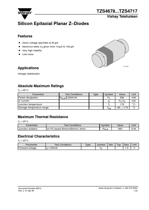
Tj = 25°C 100
10
5 IZ=5mA 0
IZ=5mA 10
DVZ
1 0
95 9598
–5 0 10 20 30 40 50 VZ – Z-Voltage ( V )
5
10
15
20
25
VZ – Z-Voltage ( V )
x
Type
Symbol PV IZ Tj Tstg
Value 500 PV/VZ 175 –65...+175
Unit mW mA °C °C
Maximum Thermal Resistance
Tj = 25_C Parameter Junction ambient Test Conditions on PC board 50mmx50mmx1.6mm Symbol RthJA Value 500 Unit K/W
Max. V 1.890 2.100 2.310 2.520 2.835 3.150 3.465 3.780 4.095 4.515 4.935 5.355 5.880 6.510 7.140 7.875 8.610 9.135 9.555 10.50 11.55 12.60 13.65 14.70 15.75 16.80 17.85 18.90 19.95 21.00 23.10 25.20 26.25 28.35 29.40 31.50 34.65 37.80 40.95 45.15
www.vishay.de • FaxBack +1-408-970-5600 2 (6)
Document Number85613 Rev. 2, 01-Apr-99
MMSZ4685T1中文资料
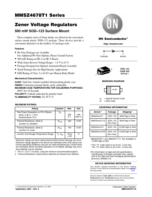
Symbol
Parameter
VZ
Reverse Zener Voltage @ IZT
IZT
Reverse Current
IR
Reverse Leakage Current @ VR
VR
Reverse Voltage
IF
Forward Current
VF
Forward Voltage @ IF
I IF
θVZ, TEMPERATURE COEFFICIENT (mV/°C)
TYPICAL CHARACTERISTICS
θVZ, TEMPERATURE COEFFICIENT (mV/°C)
8 7 6 TYPICAL TC VALUES 5 4 3
2 1 0 −1
VZ @ IZT
100 TYPICAL TC VALUES
PD
(Note 1) @ TL = 75°C
500
mW
Derated above 75°C
6.7 mW/°C
Thermal Resistance, (Note 2) Junction−to−Ambient
RqJA
340
°C/W
Thermal Resistance, (Note 2) Junction−to−Lead
DN
15.20
16
16.80
50
MMSZ4704T1
DP
16.15
17
17.85
50
MMSZ4705T1
DT
17.10
18
18.90
50
MMSZ4706T1
DU
18.05
19
19.95
MMSZ4686-F中文资料

Rev. A/AH 2007-12-14 Page 1 of 3
元器件交易网
500mW Two Terminals SMD Zener Diodes
MMSZ4685-F – MMSZ4717-F
Electrical Characteristics (T Ambient=25ºC unless noted otherwise)
TAITRON COMPONENTS IO BRASIL LTDA
RUA DOMINGOS DE MORAIS, 2777, 2.ANDAR, SALA 24 SAÚDE - SÃO PAULO-SP 04035-001 BRAZIL Tel: +55-11-5574-7949 Fax: +55-11-5572-0052
VZ(V)
Min. 3.42 3.71 4.09 4.47 4.85 5.32 5.89 6.46 7.13 7.79 8.27 8.65 9.5 10.5 11.4 12.4 13.3 14.3 15.2 16.2 17.1 18.1 19.0 20.9 22.8 23.8 25.7 26.6 28.5 31.4 34.2 37.1 40.9 Max. 3.78 4.10 4.52 4.94 5.36 5.88 6.51 7.14 7.88 8.61 9.14 9.56 10.5 11.6 12.6 13.7 14.7 15.8 16.8 17.9 18.9 20.0 21.0 23.1 25.2 26.3 28.4 29.4 31.5 34.7 37.8 41.0 45.2
元器件交易网
500mW Two Terminals
SMD Zener Diodes MMSZ4685-F – MMSZ4717-F
MMSZ4684中文资料

2.52 2.84 3.15 3.47 3.78 4.10 4.52 4.94 5.36 5.88 6.51 7.14 7.88 8.61 9.14 9.56 10.5 11.6 12.6 13.7 14.7 15.8 16.8 17.9 18.9 20.0 21.0 23.1 25.2 26.3 28.4 29.4 31.5 34.7 37.8 41.0 45.2
SYMBOL
MIN.
TYP.
MAX.
UNIT
Thermal Resistance Junction to Ambient Air Forward Voltage at IF = 10 mA
RΘJA VF
– –
– –
340(1) 0.9
°C/W Volts
NOTES: (1) FR-4 or FR-5 board with minimum recommended solder pad layout.
ห้องสมุดไป่ตู้
MAXIMUM RATINGS AND ELECTRICAL CHARACTERISTICS
Ratings at 25°C ambient temperature unless otherwise specified.
SYMBOL
VALUE
UNIT
Zener Current (see Table “Characteristics”) Power Dissipation at TL = 75°C Maximum Junction Temperature Storage Temperature Range Ptot Tj TS 500(1) 150 -55 to +150 mW °C °C
Test Voltage VR (Volts)
MM440_[Chinese]
![MM440_[Chinese]](https://img.taocdn.com/s3/m/4755b49cdd88d0d233d46ac2.png)
矢 量 型
MM440
Standard Drives A&D SD
A&D SD PRODUCT 4
1
MICROMASTER 440 - 技 术 性 能 概 要
有 A, B, C, D, E, F 六 种 外 形 结 构 的 机 壳 输 出 功 率 可 达 75 kW (恒 力 矩 )或 90 kW ( 变 力 矩) 矢 量 控 制 (无 编 码 器 ) 6 DI, 2 AI, 3 DO (继 电 器 ), 2 AO 集成的制动斩波器 恒 力 矩 方 式 下 过 载 能 力 为 200% 额 定 电 流 ,持 续 时 间 3 秒; 150% 额 定 电 流 ,持 续 时 间 60 秒;过 载 间 隔 时 间 5 分 钟 集 成 的 高 性 能 PID 控 制 器 (参 数 自 动 整 定 ) 通 过 了 CE, UL, CUL和 c-tick 的 认 证 防 护 等 级 为 IP20 / NEMA 1 输 出 频 率 0 - 650Hz 直流制动和复合制动功能 工 作 环 境 温 度 -10°C to 50°C 内 部 互 连 采 用 BiCo 技 术
Standard Drives A&D SD
A&D SD PRODUCT 4
6
MICROMASTER 440
矢量控制
输出频率 输 出 频 率 不 超 过 200 Hz ( V/ f工 作 方 式 时 可 达 650 Hz)
具有磁通监控的完整电动机模型 甚 至 在 频 率 < 2 Hz 和反 转 时 也 有 优 良 的 力 矩 输 出 特 性
电 动 机 识 别 程序 监 测 电 动 机 的 全 部 电 抗 ,实 现 可 靠 的 闭 环 控 制[或 :调 节]
深圳市美思星 CR6848 产品说明书

深圳市美思星科技有限公司代理商:深圳市美思星科技有限公司低功耗电流模www.szmsx CR6848产品说明书CR6848PWM 反激控制芯片深圳市美思星科技有限公司概述:CR6848是一款高集成度、低功耗的电流模PWM 控制芯片,适用于离线式AC-DC 反激拓扑的小功率电源模块。
芯片可以通过外接电阻改变PWM 的工作频率;在轻载和无负载情况下,芯片自动进入PFM 工作模式,可以有效地减小电源模块的待机功耗,达到绿色节能的目的。
CR6848具有很低的启动电流,一个1.5M 欧姆的启动电阻可以采用。
为了提高系统的稳定性和防止次谐波振荡,芯片内部集成了同步斜坡补偿电路;而梯形功率限制电路可以有效地减小由于系统延时而带来的输出功率变化,降低外围变压器和功率管损坏的可能性。
对于功率管翻转引入的开关噪声,通过芯片内部集成的前沿消隐电路可以有效的滤除,结合内部的过压保护和过流保护,大大地提高电源模块的可靠性。
另外,输出驱动的高电平被钳位在16.5V 以下,保证较高VCC 时,外部功率管不会因栅击穿而损坏;驱动死区时间的引入减小了驱动时的贯通电流,而内部软驱动电路则大大降低了功率管的开关噪声。
特点:电流模式PWM 控制 低启动电流 低工作电流 极少的外围元件片内自带前沿消隐 (300nS) 额定输出功率限制欠压锁定 (12.1V~16.1V) 内建同步斜坡补偿 PWM 工作频率可调 输出电压钳位 (16.5V) PWM&PFM 相结合 周期电流限制 软驱动2000V 的ESD 保护 过载保护过压保护(26.7V )SOT-23-6L 、DIP8无铅封装应用:本芯片适用于:电池充电器、机顶盒电源、DVD 电源、小功率电源适配器等60瓦以下(包括60瓦)的反激电源模块。
图 1 CR6848应用简图深圳市美思星科技有限公司印章信息引脚描述符号 输入/输出 引脚描述GATE 输出 图腾柱输出驱动外围功率管、最高电平被钳位在16.5V 以下VCC 电源地 芯片电源SENCE 输入 变压器初级电流检测,通过该脚可以调节最大峰值电流RI 输入 外接100K 电阻到地,PWM 频率为58kHz ;改变该电阻,频率改变FB 输入电流反馈输入,I FB >0.92mA 时进入PFM 模式 GND电源地芯片地深圳市美思星科技有限公司推荐工作参数符号 参数范围 单位VCC 芯片供电电源 12~ 15 VT A工作环境温度-30 ~ 105℃R RI RI 脚电阻 100 K Ω极限参数:符号 参数值单位供电电压 30 V 保护电压 27 V VCC保护电流 20 mAV FB FB 脚输入电压 -0.3 ~ +6.8 VV SENCE SENCE 脚输入电压 -0.3 ~ +6.8 VPD 输入功率 300 mWSOT-26 208 ℃/W R JA 热阻(芯片到环境)DIP8 82℃/W T J 工作时芯片温度 150 ℃T STG 储存温度范围 -55 ~ 150 ℃ 20秒 SOT26220 ℃ T L 焊接温度10秒 DIP8260℃静电保护(人体模式) 2KVESD静电保护(机械模式) 200 V深圳市美思星科技有公司电气特性: (T A =25℃,VCC=16V)VCC 端工作电压&电流参数符号 描述测试条件最小值典型值最大值单位V ON 启动电压 15.1 16.1 16.6 V V OFF 关闭电压 10.1 11.1 12.1 V V PROTECT 保护电压 26.7 V I START 启动电流 20 uA I OPS 工作电流I FB =0mA1.46mA脉冲宽度调制参数符号描述测试条件最小值典型值 最大值 单位F PWM PWM 工作时频率 RI=100K 53 58 63 kHzD PWM PWM 工作时最大占空比 75 %I FB_PFM PWM 和PFM 转折点FB 反馈电流 0.92 mA反馈端FB 参数符号描述测试条件最小值典型值最大值单位V OLP FB 开路电压 4.8 V I SHORTFB 短路电流 2.8 mAI FB_PFMS PWM 和PFM 转折点FB 反馈电流0.92 mAZ FB FB 端输入阻抗 1.26 K Ω电流检测SENCE 端参数符号 描述 测试条件最小值典型值最大值单位V S-MAX 峰值限制高电平 1 1.05 VV S-MIN 峰值限制低电平 0.83 0.87 V T PD 峰值限制系统延时 175 nSI S _SHORT SENCE 端短路电流 17 uA驱动输出GATE 端参数符号 描述测试条件最小值典型值 最大值 单位V OH 输出低电平时最高电压 I 0=-20mA VCC=16V 1.5 V V OL 输出高电平时最低电压 I 0=20mA VCC=16V 9 V T R 上升时间 CL=1nF VCC=16V 105 nsec T F下降时间CL=1nF vcc=16V56nsecT BLANK 前沿消隐时间300 nsec V CLAMP GATE 输出钳位电压 VCC=20V16.5 V深圳市美思星科技有限公司参数曲线图 2 启动电压(V ON )随温度变化图4 关闭电压(V OFF )随温度变化图 6 过压保护点随温度的变化图 8 PWM 最大占空比随温度变化图 3 启动电流随温度变化图 5 静态电流随温度变化图 7 PWM 振荡频率随温度变化图 9 PWM 频率随FB 电流变化深圳市美思星科技有限公司图 10 PWM 工作频率随RI 电阻的变化内部模块框图图 11 CR6848内部模块框图注:本公司保留修改该电路而无需特别通知的权利深圳市美思星科技有限公司功能描述:电流模控制电流控制比电压控制多了一个电流反馈环节。
MMSZ4xxxT1G系列和SZMMSZ4xxxT1G系列零点电阻电源器件的商品说明书

MMSZ4686T1G MMSZ4686T1G.MMSZ4xxxT1G Series, SZMMSZ4xxxT1G Series Zener Voltage Regulators 500 mW, Low I ZT SOD−123 Surface MountThree complete series of Zener diodes are offered in the convenient, surface mount plastic SOD−123 package. These devices provide a convenient alternative to the leadless 34−package style.Features•500 mW Rating on FR−4 or FR−5 Board•Wide Zener Reverse V oltage Range − 1.8 V to 43 V•Low Reverse Current (I ZT) − 50 m A•Package Designed for Optimal Automated Board Assembly •Small Package Size for High Density Applications•ESD Rating of Class 3 (>16 kV) per Human Body Model•SZ Prefix for Automotive and Other Applications Requiring Unique Site and Control Change Requirements; AEC−Q101 Qualified and PPAP Capable•These Devices are Pb−Free and are RoHS Compliant*Mechanical Characteristics:CASE:V oid-free, transfer-molded, thermosetting plastic case FINISH:Corrosion resistant finish, easily solderableMAXIMUM CASE TEMPERATURE FOR SOLDERING PURPOSES: 260°C for 10 SecondsPOLARITY:Cathode indicated by polarity band FLAMMABILITY RATING:UL 94 V−0MAXIMUM RATINGSRating Symbol Max Units Total Power Dissipation on FR−5 Board,(Note 1) @ T L = 75°CDerated above 75°C P D5006.7mWmW/°CThermal Resistance, (Note 2) Junction−to−Ambient R q JA340°C/WThermal Resistance, (Note 2) Junction−to−Lead R q JL150°C/WJunction and Storage Temperature Range T J, T stg−55 to+150°CStresses exceeding those listed in the Maximum Ratings table may damage the device. If any of these limits are exceeded, device functionality should not be assumed, damage may occur and reliability may be affected.1.FR−5 = 3.5 X 1.5 inches, using the minimum recommended footprint.2.Thermal Resistance measurement obtained via infrared Scan Method.*For additional information on our Pb−Free strategy and soldering details, please download the ON Semiconductor Soldering and Mounting Techniques Reference Manual, SOLDERRM/D.Cathode AnodeSee specific marking information in the device marking column of the Electrical Characteristics table on page 3 of this data sheet.DEVICE MARKING INFORMATIONSOD−123CASE 425STYLE 1Device Package Shipping†ORDERING INFORMATIONMARKING DIAGRAM†For information on tape and reel specifications, including part orientation and tape sizes, please refer to our T ape and Reel Packaging Specifications Brochure, BRD8011/D.MMSZ4xxxT1G SOD−123(Pb−Free)3,000 /Tape & ReelMMSZ4xxxT3G SOD−123(Pb−Free)10,000 /Tape & Reel xx= Device Code (Refer to page 3)M= Date CodeG= Pb−Free Package(Note: Microdot may be in either location)1SZMMSZ4xxxT1G SOD−123(Pb−Free)3,000 /Tape & ReelSZMMSZ4xxxT3G SOD−123(Pb−Free)10,000 /Tape & ReelELECTRICAL CHARACTERISTICS (T A = 25°C unless otherwise noted, V F = 0.9 V Max. @ I F = 10 mA)Symbol ParameterV Z Reverse Zener Voltage @ I ZTI ZT Reverse CurrentI R Reverse Leakage Current @ V RVR Reverse VoltageI F Forward CurrentV F Forward Voltage @ I FProduct parametric performance is indicated in the Electrical Characteristics for the listed test conditions, unless otherwise noted. Product performance may not be indicated by the Electrical Characteristics if operated under different conditions.ELECTRICAL CHARACTERISTICS (T A = 25°C unless otherwise noted, V F = 0.9 V Max. @ I F = 10 mA)Device*DeviceMarkingZener Voltage (Note 3)Leakage CurrentV Z (Volts)@ I ZT I R @ V RMin Nom Max m A m A VoltsMMSZ4678T1G CC 1.71 1.8 1.89507.51 MMSZ4679T1G CD 1.90 2.0 2.105051 MMSZ4680T1G CE 2.09 2.2 2.315041 MMSZ4681T1G CF 2.28 2.4 2.525021 MMSZ4682T1G CH 2.565 2.7 2.8355011 MMSZ4683T1G CJ 2.85 3.0 3.15500.81 MMSZ4684T1G CK 3.13 3.3 3.47507.5 1.5 MMSZ4685T1G CM 3.42 3.6 3.78507.52 MMSZ4686T1G CN 3.70 3.9 4.105052 MMSZ4687T1G CP 4.09 4.3 4.525042 SZMMSZ4687T1G CG6 4.09 4.3 4.525042 MMSZ4688T1G CT 4.47 4.7 4.9450103 MMSZ4689T1G CU 4.85 5.1 5.3650103 MMSZ4690T1G/T3G CV 5.32 5.6 5.8850104 MMSZ4691T1G CA 5.89 6.2 6.5150105 MMSZ4692T1G CX 6.46 6.87.145010 5.1 MMSZ4693T1G CY7.137.57.885010 5.7 MMSZ4694T1G CZ7.798.28.61501 6.2 MMSZ4695T1G DC8.278.79.14501 6.6 MMSZ4696T1G DD8.659.19.56501 6.9 MMSZ4697T1G DE9.501010.505017.6 MMSZ4698T1G DF10.451111.55500.058.4 MMSZ4699T1G DH11.401212.60500.059.1 MMSZ4700T1G DJ12.351313.65500.059.8 MMSZ4701T1G DK13.301414.70500.0510.6 MMSZ4702T1G DM14.251515.75500.0511.4 MMSZ4703T1G†DN15.201616.80500.0512.1 MMSZ4704T1G DP16.151717.85500.0512.9 MMSZ4705T1G DT17.101818.90500.0513.6 MMSZ4706T1G DU18.051919.95500.0514.4 MMSZ4707T1G DV19.002021.00500.0115.2 MMSZ4708T1G DA20.902223.10500.0116.7 MMSZ4709T1G DX22.802425.20500.0118.2 MMSZ4710T1G DY23.752526.25500.0119.0 MMSZ4711T1G†EA25.652728.35500.0120.4 MMSZ4712T1G EC26.602829.40500.0121.2 MMSZ4713T1G ED28.503031.50500.0122.8 MMSZ4714T1G EE31.353334.65500.0125.0 MMSZ4715T1G EF34.203637.80500.0127.3 MMSZ4716T1G EH37.053940.95500.0129.6 MMSZ4717T1G EJ40.854345.15500.0132.6 3.Nominal Zener voltage is measured with the device junction in thermal equilibrium at T L = 30°C ±1°C.*Include SZ-prefix devices where applicable.†MMSZ4703 and MMSZ4711 Not Available in 10,000/Tape & ReelTYPICAL CHARACTERISTICSV Z , T E M P E R A T U R E C O E F F I C I E N T (m V /C )°θV Z , NOMINAL ZENER VOLTAGE (V)Figure 1. Temperature Coefficients (Temperature Range −55°C to +150°C)V Z , T E M P E R A T U R E C O E F F I C I E N T (m V /C )°θ100101V Z , NOMINAL ZENER VOLTAGE (V)Figure 2. Temperature Coefficients (Temperature Range −55°C to +150°C)1.21.00.80.60.40.20T, TEMPERATURE (5C)Figure 3. Steady State Power Derating P p k, P E A K S U R G E P O W E R (W A T T S )PW, PULSE WIDTH (ms)Figure 4. Maximum Nonrepetitive Surge PowerP D , P O W E R D I S S I P A T I O N (W A T T S )V Z , NOMINAL ZENER VOLTAGEFigure 5. Effect of Zener Voltage onZener ImpedanceZ Z T , D Y N A M I C I M P E D A N C E ()ΩTYPICAL CHARACTERISTICSC , C A P A C I T A N C E (p F )V Z , NOMINAL ZENER VOLTAGE (V)Figure 6. Typical Capacitance 1000100101V Z , ZENER VOLTAGE (V)1001010.10.01I Z , Z EN E R C U R R E N T (m A )V Z , ZENER VOLTAGE (V)1001010.10.01I R , L E A K A G E C U R R E N T (A )μV Z , NOMINAL ZENER VOLTAGE (V)Figure 7. Typical Leakage Current10001001010.10.010.0010.00010.00001I Z , Z E N E R C U R R E N T (m A )Figure 8. Zener Voltage versus Zener Current(V Z Up to 12 V)Figure 9. Zener Voltage versus Zener Current(12 V to 91 V)SOD−123CASE 425−04ISSUE GDATE 07 OCT 2009SCALE 5:1NOTES:1.DIMENSIONING AND TOLERANCING PER ANSIY14.5M, 1982.2.CONTROLLING DIMENSION: INCH.DIM MIN NOM MAXMILLIMETERSINCHESA0.94 1.17 1.350.037A10.000.050.100.000b0.510.610.710.020c1.600.150.055D 1.40 1.80E 2.54 2.69 2.840.100---3.680.140L0.253.860.0100.0460.0020.0240.0630.1060.1450.0530.0040.0280.0710.1120.152MIN NOM MAX3.56H E---------0.006------------GENERICMARKING DIAGRAM**For additional information on our Pb−Free strategy and solderingdetails, please download the ON Semiconductor Soldering andMounting Techniques Reference Manual, SOLDERRM/D.SOLDERING FOOTPRINT**This information is generic. Please refer to device datasheet for actual part marking. Pb−Free indicator, “G” ormicrodot “ G”, may or may not be present.XXX= Specific Device CodeM= Date CodeG= Pb−Free Package1STYLE 1:PIN 1. CATHODE2. ANODE0.910.036ǒmminchesǓSCALE 10:1------q001010°°°°(Note: Microdot may be in either location) MECHANICAL CASE OUTLINEPACKAGE DIMENSIONSON Semiconductor and are trademarks of Semiconductor Components Industries, LLC dba ON Semiconductor or its subsidiaries in the United States and/or other countries.ON Semiconductor reserves the right to make changes without further notice to any products herein. ON Semiconductor makes no warranty, representation or guarantee regarding the suitability of its products for any particular purpose, nor does ON Semiconductor assume any liability arising out of the application or use of any product or circuit, and specifically disclaims any and all liability, including without limitation special, consequential or incidental damages. ON Semiconductor does not convey any license under its patent rights nor theON Semiconductor and are trademarks of Semiconductor Components Industries, LLC dba ON Semiconductor or its subsidiaries in the United States and/or other countries.ON Semiconductor owns the rights to a number of patents, trademarks, copyrights, trade secrets, and other intellectual property. A listing of ON Semiconductor’s product/patent coverage may be accessed at ON Semiconductor makes no warranty, representation or guarantee regarding the suitability of its products for any particular purpose, nor does ON Semiconductor assume any liability arising out of the application or use of any product or circuit, and specifically disclaims any and all liability, including without limitation special, consequential or incidental damages.PUBLICATION ORDERING INFORMATIONTECHNICAL SUPPORTNorth American Technical Support:Voice Mail: 1 800−282−9855 Toll Free USA/Canada Phone: 011 421 33 790 2910LITERATURE FULFILLMENT :Email Requests to:*******************ON Semiconductor Website: Europe, Middle East and Africa Technical Support:Phone: 00421 33 790 2910For additional information, please contact your local Sales RepresentativeMMSZ4686T1G MMSZ4686T1G.。
MMSZ4707中文资料

MAXIMUM RATINGS AND ELECTRICAL CHARACTERISTICS
Ratings at 25°C ambient temperature unless otherwise specified.
SYMBOL
VALUE
UNIT
Zener Current (see Table “Characteristics”) Power Dissipation at TL = 75°C Maximum Junction Temperature Storage Temperature Range Ptot Tj TS 500(1) 150 -55 to +150 mW °C °C
2.00 1.00 0.80 7.50 7.50 5.00 4.00 10.0 10.0 10.0 10.0 10.0 10.0 1.00 1.00 1.00 1.00 0.05 0.05 0.05 0.05 0.05 0.05 0.05 0.05 0.05 0.01 0.01 0.01 0.01 0.01 0.01 0.01 0.01 0.01 0.01 0.01
2.52 2.84 3.15 3.47 3.78 4.10 4.52 4.94 5.36 5.88 6.51 7.14 7.88 8.61 9.14 9.56 10.5 11.6 12.6 13.7 14.7 15.8 16.8 17.9 18.9 20.0 21.0 23.1 25.2 26.3 28.4 29.4 31.5 34.7 37.8 41.0 45.2
NOTES: (1) Measured with device junction in thermal equilibrium
Test Voltage VR (Volts)
W78E58中文
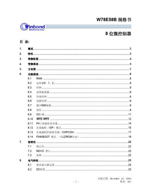
W78E58B规格书8位微控制器目录:1.概述 (3)2.特性 (3)3.管脚配置 (4)4.管脚描述 (5)5.方块图 (7)6.功能描述 (8)6.1 RAM (8)6.2 定时器0,1,2 (8)6.3 时钟 (9)6.4 晶体振荡器 (9)6.5 外部时钟 (9)6.6 电源管理 (9)6.7 减少EMI辐射 (9)6.8 复位 (9)6.9 I/O口4 (11)6.10 INT2/INT3 (12)6.11 P4口基地址寄存器 (14)6.12 在线编程(ISP)模式 (15)6.13 在线编程控制寄存器(CHPCON) (17)6.14 F04KBOOT 模式(从LDROM启动) (18)7.保密位 (22)7.1 锁止位 (22)禁止 (22)7.2 MOVC7.3 加密 (22)8.电气特性 (23)8.1 绝对最大额定值 (23)8.2 DC特性 (23)出版日期: December 22, 20048.3 AC特性 (25)8.3.1时钟输入波形 (25)8.3.2程序读取周期 (26)8.3.3数据读取周期 (26)8.3.4数据写周期 (27)8.3.5端口访问周期 (27)9.时序波形图 (28)9.1 程序读取周期 (28)9.2 数据读周期 (28)9.3 数据写周期 (29)9.4 端口访问周期 (29)10.典型应用电路 (30)10.1 扩展的外部程序存储器和石英晶体 (30)10.2 扩展的外部程序存储器和振荡器 (31)11.封装尺寸 (32)11.1 DIP40 (32)11.2 44 管脚PLCC (33)11.3 44 管脚PQFP (34)12.应用指南 (35)12.1 ISP 软件编程示例: (35)13.文件版本描述 (42)1. 概述W78E58B是具有带ISP功能的Flash EPROM的低功耗8位微控制器;ISP功能的Flash EPROM可用于固件升级。
洛阳特重轴承-中文电子样本

额定负荷重量型 号Basic Loads Mass DesignationsD d H D1D2φ1φ2D3d1H1h φ3Coa mm 104 N kg 116752480260604442961616141436038060---75.455116752K48026060------36038060---75.458.617679259046045570488812M101051854245---62.635.9176792K590460455704881212101051854245---62.636176792K2M59046045570488128101052653445---94.430.81167/530780530607405602020171364566535---1121031167/5607205603669059012121412638.5641.5333-70.840.31167/560K720560366905901232M1216634646363-70.839.21167/560M7205603669059012121412638.5641.5363-70.838.11168/56078056060------645668603-22410311768/63078063069------71872269---11179.41167/700900700368607401212M1617796804363--17960E787/760G295076080915795242418M16853.5856.57194M10×12031383 - 6401000775649488022412/12M1213 / M1287888249152M8×11961123 - 640K1000775649488022412/12M1212 / M1287888249152M8196112787/800G10508009010128383030202092392776163M10×121519271769/850Y11208508510749241212M2022995101085---15l 24871769/850G2K112085085107492412121722999l00385---210257787/932G212009321201148984404026M2410641068100204G1 / 4in 349328787/960G211659609011351040363618M161073107778146M10×1249202787/1000G21250100010012061044121218M161123112790103M10×1540283787/1260G2150912609014651315363622M201386138970142ZGL / 8in 37827471169/1400Y18201400136175014702424353516081612136-4M10×1611111471169/1400Y118201400136175014702424353516081612136-4M10×110701120787/1440G21780144010017301494484822M201618162285154M12×1.25503533787/1628G21927162813018751680363626M2417741778115156G1 / 4in 692732787/1700KM20001700150195017502424212118421858130204M10×1684826KDL900—610508325610208621212181894294645-4M622752.5LD—Q00748527555453307161618M163813865054M10×187.243.7LD—QOO7K48527555453307161618183813865054M10×187.243.7LD—Q020440240554002801818M20-7H 223403425053M10×178.234.74 point contact ball bearing slewing ring (without gear)四点接触球式转盘轴承(无齿式)n1n2n3mm mm mm mm 外 形 尺 寸安 装 孔 尺 寸结 构 尺 寸Boundary Dimensions Bolt Hole Diameter Structure Dimensions额定负荷重量型 号Basic Loads Mass DesignationsD d H D1D2φ1φ2D3d1H1h φ3Da b Coa mm mm mm 104 N kg D178794694470776305001818M1618567.5564.564136M10 x1669611460015793.11787/600G786600727406362024 2.5196896916074n 678913150010794.11787/674G285367470825709342320M2076476859102n 78891255001838911787/674G2K853674708257093424181876476859102n 788912550018388.61787/710G28947106784574488M10M107988065893M10×l 69241525501791071787/710G2K89471067875760812M10M127988065893M10×169241525501791071787/710G2Kl89471067865744202013137988065894M10 x169241525501791071787/800G 10508009010128383030202092392776163M10×1610921806002152171787/800GK 10508009010128383030202092392776163M10×1610921806002152171788/1040G2 -104080122010803030M1617.5115311577010--10131412570029725l 1787/1060G 13351060109129511052424M20221198120210094M8×110138813880-0.65014071787/107513651075120131011303636262612181222105154M8×1814241769004634631787/1075K 1365107513013101130363624241218122210510--10142014012004635501787/1075G21365107512013lO 11303636242412181222105154M10 x110142513890 1.44634631787/1075G2K 1365107512013lO 11303636M242612181222105154M8×1814241'769004634631787/1330G21475133082.415101362242418.518.5143914457012.46M10×1915841747003532803 — 647G 14071352100137014041813M8M101390139463-86 4.514493206002161431788/1410G2-141085159014543636M1617.51524.61528.67015--1016761607003953121787/1640G 20501640160199017103030282818441856140202 1.5102108210105-0.6111812641787/170019451700120190017502424M182118251845110104M10×1519703923504055161789/1700GM 2052170010019801780242420M181878188290104 1.5520804145005516781787/2650G228852650100285027004848 M20M202777278180106n 122950244800913751Z x mm mm mm mm n1n2n3m Boundary Dimensions Bolt Hole Diameter Structure Dimensions Gear Parameters 外 形 尺 寸安 装 孔 尺 寸结 构 尺 寸齿 轮 参 数额定负荷重量型 号Basic Loads Mass DesignationsD d H D1D2φ1φ2D3d1H1h φ3da b Coa mm mm mm 104 N kg 2788/850K97685080------91691980---29164562001741173-646G21200-5611701044162417.510.51088109246124M8 x1698516644021084.12782/1000GK127010001001220105024/2×224/2×217/M1217/M121133113785152M10×16972.61647003843222787/1210G215301210122148012604040262613681372108124M10 x11011641188007135402787/1400GK17151400110166014602424M20M201558156295152M121.256136523077-0.353655452787/1400GK11715140011016601460242423231558156295152M10x16136523077-0.353655452787/14401780144010017301494484822M201618162285104M121.25814001775005035542787/1440G1780144010017301494484822M201618162285104M121.25814001775005785542768/1440G1780144010417301494484822M201613162787106M121.25814001775205785552787/1525G218751525140181515854242292916981702122174M121.25161452921100.3587310192788/171220501790112200618473672222219251926921218M10x1161712108100-0.56046632789/223024882230160244522754848M20M222337.52342.513558ZG1/4in 1821441211450124711142789/2240G225002240140245422805656M24M242357.52362.511558M14x1.5182146121125085611612789/273529902735160295427704848M20M242835284513558ZG1/4in 222625121144015591457Z x mm mm mm mm n1n2n3m Boundary Dimensions Bolt Hole Diameter Structure Dimensions Gear Parameters 外 形 尺 寸安 装 孔 尺 寸结 构 尺 寸齿 轮 参 数50Ball and roller combined slewing bearing (external gear)球柱组合转盘轴承重量De D d H D1D2фMD3d1H1hb 正常最大mm mm mm mmmm mm mm mm mm mm mm mm KN KN 221.32.3550.**3772.83358159363834187630271035913509143501091623210.11603202028221.32.3750.**3980.8355815938463618803027103791370914350109162460.50.11603202186221.32.4000.**4220.8380815940863868843027124041395914350109162610.50.11603202278221.32.4250.**4476.84058159434241189030271242914209143501091627610.11603202455221.36.4000.**4244.43792175409538587633301240453955159501251823210.11963912792221.36.4250.**4496.4404217543474108803330124295420515950125182470.50.11963912981221.36.4500.**4748.4429217545994358843330144545445515950125182610.50.11963913171221.36.4750.**5000.4454217548514608903330144795470515950125182750.50.11963913363221.40.4500.**4776427618346124348723633144550445016750133202360.50.12314633673221.40.4750.**5016452618348524598763633144800470016750133202480.50.12314633796轴 承 型 号 (外齿式)n n1m Z x k kg 外 形 尺 寸安 装 尺 寸结 构 尺 寸齿 轮 参 数齿轮圆周力Boundary dimensions Installation dimesnions Fabrication dimensionsGear data。
FAIRCHILD MMSZ4688 说明书

Absolute Maximum RatingsParameterT STG- Storage TemperatureT J- Maximum Junction TemperatureP D- Total Power Dissipation at 25Derate above 25RØJA- Thermal Resistance Junction to AmbientVLead Solder Temperature (Max 10 second duration)Dimensions are in millimeterPkg type A0B0WD0D1E1E2FP1P0K0TWcTcSOD123(8mm)1.85+/-0.103.94+/-0.108.0+/-0.31.50+/-0.101.125+/-0.1251.75+/-0.106.25min3.50+/-0.054.0+/-0.14.0+/-0.11.50+/-0.100.200+/-0.0205.2+/-0.20.06+/-0.02P1A0D1P0FWE1D0E2B0TcWcK0TDimensions are in inches and millimetersTape SizeReel OptionDim ADim BDim CDim DDim NDim W1Dim W2Dim W3 (LSL-USL)8mm7" Dia7.00177.80.0591.5512 +0.020/-0.00813 +0.5/-0.20.79520.2 2.165550.331 +0.059/-0.0008.4 +1.5/00.56714.40.311 – 0.4297.9 – 10.98mm 13" Dia13.003300.0591.5512 +0.020/-0.00813 +0.5/-0.20.79520.24.001000.331 +0.059/-0.0008.4 +1.5/00.56714.40.311 – 0.4297.9 – 10.9See detail AADim A max13" Diameter Option7" Diameter OptionDim A MaxSee detail AAW3W2 max Measured at HubW1 Measured at HubDim NDim D minDim CB Min DETAIL AANotes: A0, B0, and K0 dimensions are determined with respect to the EIA/Jedec RS-481rotational and lateral movement requirements (see sketches A, B, and C).20 deg maximum component rotation0.5mm maximum0.5mm maximumSketch C (Top View)Component lateral movementTypical component cavitycenter line20 deg maximumTypical component center lineB0A0Sketch B (Top View)Component RotationSketch A (Side or Front Sectional View)Component RotationUser Direction of FeedSOD123 Embossed Carrier Tape Configuration: Figure 3.0SOD123 Reel Configuration: Figure 4.0SOD-123 (FS PKG Code D6)TRADEMARKSACEx™Bottomless™CoolFET™CROSSVOLT™E 2CMOS TM FACT™FACT Quiet Series™FAST FASTr™GTO™The following are registered and unregistered trademarks Fairchild Semiconductor owns or is authorized to use and is not intended to be an exhaustive list of all such trademarks.LIFE SUPPORT POLICYFAIRCHILD’S PRODUCTS ARE NOT AUTHORIZED FOR USE AS CRITICAL COMPONENTS IN LIFE SUPPORTDEVICES OR SYSTEMS WITHOUT THE EXPRESS WRITTEN APPROV AL OF FAIRCHILD SEMICONDUCTOR CORPORATION.As used herein:1. Life support devices or systems are devices or systems which, (a) are intended for surgical implant intothe body, or (b) support or sustain life, or (c) whosefailure to perform when properly used in accordancewith instructions for use provided in the labeling, can be reasonably expected to result in significant injury to the user.2. A critical component is any component of a lifesupport device or system whose failure to perform can be reasonably expected to cause the failure of the life support device or system, or to affect its safety or effectiveness.PRODUCT STATUS DEFINITIONS Definition of Terms Datasheet Identification Product Status DefinitionAdvance InformationPreliminary No Identification Needed Obsolete This datasheet contains the design specifications for product development. Specifications may change in any manner without notice.This datasheet contains preliminary data, andsupplementary data will be published at a later date.Fairchild Semiconductor reserves the right to make changes at any time without notice in order to improve design.This datasheet contains final specifications. Fairchild Semiconductor reserves the right to make changes at any time without notice in order to improve design.This datasheet contains specifications on a product that has been discontinued by Fairchild semiconductor.The datasheet is printed for reference information only.Formative or In DesignFirst ProductionFull ProductionNot In ProductionDISCLAIMERFAIRCHILD SEMICONDUCTOR RESERVES THE RIGHT TO MAKE CHANGES WITHOUT FURTHER NOTICE TO ANY PRODUCTS HEREIN TO IMPROVE RELIABILITY , FUNCTION OR DESIGN. FAIRCHILD DOES NOT ASSUME ANY LIABILITY ARISING OUT OF THE APPLICATION OR USE OF ANY PRODUCT OR CIRCUIT DESCRIBED HEREIN; NEITHER DOES IT CONVEY ANY LICENSE UNDER ITS PATENT RIGHTS, NOR THE RIGHTS OF OTHERS.SuperSOT™-8SyncFET™TinyLogic™UHC™VCX™HiSeC™ISOPLANAR™MICROWIRE™POP™PowerTrench QFET™QS™Quiet Series™SuperSOT™-3SuperSOT™-6。
MP4688芯片资料
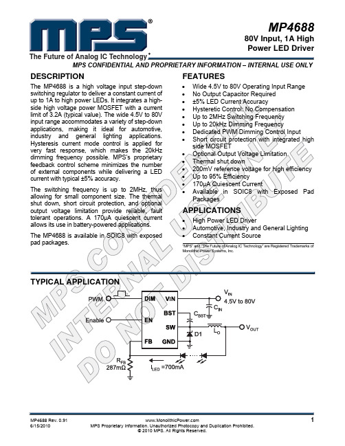
MP468880V Input, 1A High Power LED DriverMPS CONFIDENTIAL AND PROPRIETARY INFORMATION – INTERNAL USE ONLYThe Future of Analog IC TechnologyDESCRIPTIONThe MP4688 is a high voltage input step-down switching regulator to deliver a constant current ofFEATURES• Wide 4.5V to 80V Operating Input RangeORDERING INFORMATIONPart Number*Package Top Marking Free Air Temperature (T A) MP4688DN SOIC8E MP4688 –40°C to +85°CELECTRICAL CHARACTERISTICSV IN = 60V, T A= +25°C, unless otherwise noted.Specifications over temperature are guaranteed by design and characterization.PIN FUNCTIONSBLOCK DIAGRAMTYPICAL PERFORMANCE CHARACTERISTICS L=47µH, 1 LED Load, T A=25 o C, unless otherwise noted.OPERATIONHysteresis Current Control with Adaptive Threshold AdjustmentMP4688 operates in a hysteresis current control supply voltage. The UVLO rising threshold is about 4.0V while its falling threshold is a consistent 3.65V. Thermal ShutdownThermal shutdown is implemented to prevent the chip from operating at exceedingly highAPPLICATION INFORMATIONCOMPONENT SELECTIONSetting the LED CurrentThe LED current I LED is set using a sensinggreater than the maximum diode current.Input Capacitor C INThe input current to the step-down converter is discontinuous, therefore a capacitor is required to supply the AC current to the step-down (ESR) value of the output capacitor.External Bootstrap DiodeAn external bootstrap diode may enhance the efficiency of the LED driver. In below cases, an external BST diode is recommended from the 5V to BST pin: Layout ConsiderationIt is essential to place the input decoupling capacitor, catch diode and the MP4688 (VIN pin, SW pin and PGND) as close as possible, with traces that are very short and fairly wide.NOTICE: The information in this document is subject to change without notice. Users should warrant and guarantee that thirdparty Intellectual Property rights are not infringed upon when integrating MPS products into any application. MPS will not assume any legal responsibility for any said applications.PACKAGE INFORMATIONSOIC8E (EXPOSED PAD)6) DRAWING IS NOT TO SCALE.RECOMMENDED LAND PATTERN。
MMSZ4678
客户基本资料
公司名称 联系方式 收货地址 生产产品
联络人
电话:
姓名: 电话:
传真:
职务: 手机:
网址: □生产型企业
□贸易商
□技术 电邮:
□采购
□其他
样品明细资料
元器件名称 型号及封装
单机用量 申请数量 备注
预计生产情况
预计小批量生产日期:
规模生产日期:
样品申请日期:
样品申请流程
1、请详细、全面、真实填写上列各项。表格不够填写,可自行复制。 2、请以附件的形式将该文档通过 E-mail 发送,并请将此单打印盖章后,传真至:025-84710486。 3、公司将根据客户所填信息并综合相关情况,由样品小组负责确定该样品申请单是否执行及如何执行。 4、收到样品申请单并经审核通过后,南京库有现货2个工作日内发出;如需订货,交期3-4周,非常规品顺延1-2周。 5、样品免费,运费到付(一般选择顺丰快递);样品数量:单个型号5~20pcs, 或根据 BOM 表清单按2~5套提供。 6、说明:接单后,样品小组将努力跟进,但由于原厂生产等环节存有不确定因素,我们无法保证样品数量、型号完
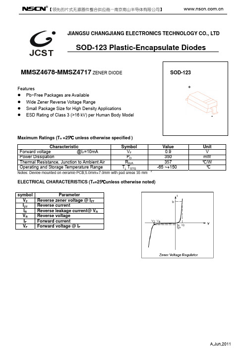
RθJA
Operating and Storage Temperature Range
Tj, TSTG
Notes: Device mounted on ceramic PCB;5.0mm×7.0mm with pad areas 35 mm 2
Value
0.9
350 357 -65 ~+150
ELECTRICAL CHARACTERISTICS (Ta=25℃unless otherwise noted)
Unit
V
mW
GR-468-CORE中文版
能力有限,翻译的不恰当的地方,请多多见谅(仅供个人学习,请勿商用)
Happy_Fei
3.1.4.2 活化能量……………………………………………………………… 33 3.1.4.3 与多重失效机理相关的附加考虑因素……………………………… 33 3.2 特性测试程序…………………………………………………………………… 34 3.2.1 光谱特性 ……………………………………………………………………… 34 3.2.1.1 MLM激光器的光谱特性………………………………………………35 3.2.1.2 SLM 激光器的光谱特性………………………………………………36 3.2.1.2.1 连续波激光器的考虑因素………………………………… 37 3.2.1.2.2 WDM激光器的考虑因素(略) 3.2.1.2.3 可调激光器的考虑因素(略) 3.2.1.2.4 高比特率应用的考虑因素………………………………… 37 3.2.1.3 LEDs的光谱特性………………………………………………37 3.2.2 输出功率/驱动电流特性…………………………………………………… 38 3.2.2.1 一般输出功率和L-I曲线测量考虑因素(略) 3.2.2.2 激光门槛电流……………………………………………………… 38 3.2.2.3 激光门槛电流的温度灵敏度……………………………………… 38 3.2.2.4 特定电流水平的输出功率水平 3. 2 .2. 4. 1 门槛电流的激光输出功率(略) 3.2.2.4.2 LED输出功率………………………………………39 3.2.2.5 激光L-I曲线的线性度…………………………………………………39 3.2.2.5.1 整体线性度…………………………………………………39 3.2.2.5.2 拐点……………………………………………………… 39 3.2.2.5.3 饱和度(略) 3.2.2.6 激光器的斜效率……………………………………………………… 40 3.2.2.7 相对强度噪声……………………………………………………… 40 3.2.2.8 EELED高效发光………………………………………………………40 3.2.2.9 EELED激光发射的门槛值……………………………………………41 3.2.3 激光器的电压 - 电流曲线………………………………………………… 41 3.2.4 调制输出特性……………………………………………………………… 41 3.2.4.1 调制信号形状…………………………………………………… 41 3.2.4.1.2 上升和下降时间…………………………………………… 42 3.2.4.2 消光比和调制深度…………………………………………………… 44 3.2.4.3 导通延迟……………………………………………………………… 44 3.2.4.4 截止频率……………………………………………………………… 45 3.2.5 可调激光器特性…………………………………………………………… 45 3.2.6 出射光场和元件排列 3.2.6.1 远场图形……………………………………………………………… 45 3.2.6.2 耦合效率……………………………………………………………… 46 3.2.6.3 前后向寻迹比值偏差………………………………………………… 46 3.2.6.4 前后向寻迹误差……………………………………………………… 47 3.2.6.5 偏振消光比…………………………………………………………… 47 3.2.7 调制器的光学和电气特性…………………………………………………… 47 3.2.7.1 EA调制器特性…………………………………………………………47 3
并联传感器系统压力传感器故障诊断系统设计

并联传感器系统压力传感器故障诊断系统设计韩成春【摘要】在工业生产过程中电子皮带秤普遍采用多个称重传感器输出信号的并联方法,而该方法对多个称重传感器无法独立采集同时无法准确判断故障;应用TI公司MSC1210单片机最小系统和信号分离器,设计一种并联传感器系统压力传感器故障诊断系统,实现多个称重传感器并联应用时的独立采集;发明一种皮带秤称重传感器累计量校准方法,将不断变化的累计量转换成定量值实现并联传感器系统压力传感器故障诊断;结果表明该系统较好实现多个称重传感器的独立采集和故障传感器判断,为皮带秤等计量装置并联传感器系统的技术升级提供有效手段.【期刊名称】《计算机测量与控制》【年(卷),期】2015(023)007【总页数】4页(P2252-2254,2258)【关键词】并联传感器系统;压力传感器;故障诊断;传感器校准方法【作者】韩成春【作者单位】徐州工程学院信电学院,江苏徐州 221111;江苏省大型工程装备检测与控制重点实验室,江苏徐州 221111【正文语种】中文【中图分类】TP277;TH865电子皮带秤作为计量、控制、管理等功能于一体广泛应用于工业生产过程中。
但由于输送皮带的张力变化、输送物料不均匀而导致的秤架两侧受压不均匀、托辊径向跳动、皮带质量偏差和皮带扣引起振动等因素将产生计量误差。
因此解决这些计量误差是本领域技术人员急需解决的技术问题[1-4]。
为了提高电子皮带秤的计量精度,一方面利用称重传感器减振装置来吸收设备运行时的振动能量[5];另一方面采用多个称重传感器同时将多个并联传感器输出信号的并联方法来计算平均累计量,以期达到简化硬件和避免任何一个称重传感器出现故障时均可正常计量,以此提高系统的可靠性。
随着计量设备智能诊断技术的日益普及,称重传感器输出信号的并联方法无法独立采集,限制了智能诊断技术的应用,仅靠人工经验管理,不仅提高在线管理难度和成本,而且无法及时掌控设备状态。
本文设计一种并联传感器系统压力传感器故障诊断系统,解决并联传感器输出信号无法独立采集问题,实现并联传感器系统压力传感器的在线监测与故障诊断。
- 1、下载文档前请自行甄别文档内容的完整性,平台不提供额外的编辑、内容补充、找答案等附加服务。
- 2、"仅部分预览"的文档,不可在线预览部分如存在完整性等问题,可反馈申请退款(可完整预览的文档不适用该条件!)。
- 3、如文档侵犯您的权益,请联系客服反馈,我们会尽快为您处理(人工客服工作时间:9:00-18:30)。
VZ(V)
Min. 3.42 3.71 4.09 4.47 4.85 5.32 5.89 6.46 7.13 7.79 8.27 8.65 9.5 10.5 11.4 12.4 13.3 14.3 15.2 16.2 17.1 18.1 19.0 20.9 22.8 23.8 25.7 26.6 28.5 31.4 34.2 37.1 40.9 Max. 3.78 4.10 4.52 4.94 5.36 5.88 6.51 7.14 7.88 8.61 9.14 9.56 10.5 11.6 12.6 13.7 14.7 15.8 16.8 17.9 18.9 20.0 21.0 23.1 25.2 26.3 28.4 29.4 31.5 34.7 37.8 41.0 45.2
Max. Reverse Leakage Current IR @ VR
IZT(mA)
0.05 0.05 0.05 0.05 0.05 0.05 0.05 0.05 0.05 0.05 0.05 0.05 0.05 0.05 0.05 0.05 0.05 0.05 0.05 0.05 0.05 0.05 0.05 0.05 0.05 0.05 0.05 0.05 0.05 0.05 0.05 0.05 0.05
Ptot RthJA TJ TSTG
Note: 1. FR-4 or FR-5 board with minimum recommended solder pad layout.
TAITRON COMPONENTS INCORPORATED
Tel: (800)-TAITRON (800)-824-8766 (661)-257-6060 Fax: (800)-TAITFAX (800)-824-8329 (661)-257-6415
TAITRON COMPONENTS INCORPORATED REPRESENTAÇÕES DO BRASIL LTDA
RUA DOMINGOS DE MORAIS, 2777, 2.ANDAR, SALA 24 SAÚDE - SÃO PAULO-SP 04035-001 BRAZIL Tel: +55-11-5574-7949 Fax: +55-11-5572-0052
元器件交易网
500mW Two Terminals
SMD Zener Diodes MMSZ4685-F – MMSZ4717-F
500mW Two Terminals SMD Zener Diodes
Features
• Silicon Planar Zener Construction • 500mW Power Dissipation • Zener Voltage 3.6v to 43v • High Temperature Soldering Guaranteed: 250 °C/10 Seconds Set Terminals • RoHS Compliance
TAITRON COMPONENTS MEXICO, S.A .DE C.V.
BOULEVARD CENTRAL 5000 INTERIOR 5 PARQUE INDUSTRIAL ATITALAQUIA, HIDALGO C.P. 42970 MEXICO Tel: +52-55-5560-1519 Fax: +52-55-5560-2190
Maximum Ratings (T Ambient=25ºC unless noted otherwise)
Symbol Description Power Dissipation Thermal Resistance Junction to Ambient Air Max. Junction Temperature Storage Temperature Range Value 500 340 150 -55 to 150 Unit mW °C/W °C °C Conditions TL=75 °C (Note 1) (Note 1)
Rev. A/AH 2007-12-14 Page 1 of 3
Байду номын сангаас
元器件交易网
500mW Two Terminals SMD Zener Diodes
MMSZ4685-F – MMSZ4717-F
Electrical Characteristics (T Ambient=25ºC unless noted otherwise)
*Norminal Zener Voltage @ IZT
Part NO. Marking Code Nom. MMSZ4685-F MMSZ4686-F MMSZ4687-F MMSZ4688-F MMSZ4689-F MMSZ4690-F MMSZ4691-F MMSZ4692-F MMSZ4693-F MMSZ4694-F MMSZ4695-F MMSZ4696-F MMSZ4697-F MMSZ4698-F MMSZ4699-F MMSZ4700-F MMSZ4701-F MMSZ4702-F MMSZ4703-F MMSZ4704-F MMSZ4705-F MMSZ4706-F MMSZ4707-F MMSZ4708-F MMSZ4709-F MMSZ4710-F MMSZ4711-F MMSZ4712-F MMSZ4713-F MMSZ4714-F MMSZ4715-F MMSZ4716-F MMSZ4717-F CM CN CP CT CU CV CA CX CY CZ DC DD DE DF DH DJ DK DM DN DP DT DU DV DA DZ DY EA EC ED EE EF EH EJ 3.6 3.9 4.3 4.7 5.1 5.6 6.2 6.8 7.5 8.2 8.7 9.1 10 11 12 13 14 15 16 17 18 19 20 22 24 25 27 28 30 33 36 39 43 Test Current
TAITRON COMPONENTS INCORPORATED, SHANGHAI REPRESENTATIVE OFFICE
METROBANK PLAZA, 1160 WEST YAN’ AN ROAD, SUITE 1503, SHANGHAI, 200052, CHINA Tel: +86-21-5424-9942 Fax: +86-21-5424-9931 Rev. A/AH 2007-12-14 Page 3 of 3
IR (μA)
7.50 5.00 4.00 10.0 10.0 10.0 10.0 10.0 10.0 1.00 1.00 1.00 1.00 0.05 0.05 0.05 0.05 0.05 0.05 0.05 0.05 0.05 0.01 0.01 0.01 0.01 0.01 0.01 0.01 0.01 0.01 0.01 0.01
SOD-123F
Mechanical Data
Case: Epoxy: Terminals: Polarity: Approx Weight: SOD-123F, molded plastic Plastic package has UL flammability 94V-0 Solderable per MIL-STD-202G,Method 208 Color band denotes cathode 0.01 grams
VR(V)
2.0 2.0 2.0 3.0 3.0 4.0 5.0 5.1 5.7 6.2 6.6 6.9 7.6 8.4 9.1 9.8 10.6 11.4 12.1 12.9 13.6 14.4 15.2 16.7 18.2 19.0 20.4 21.2 22.8 25.0 27.3 29.6 32.6
*Measured with device junction in thermal equilibrium
Rev. A/AH 2007-12-14 Page 2 of 3
元器件交易网
500mW Two Terminals SMD Zener Diodes
MMSZ4685-F – MMSZ4717-F
Dimensions in mm
SOD-123F
How to contact us
US HEADQUARTERS
28040 WEST HARRISON PARKWAY, VALENCIA, CA 91355-4162 Tel: (800) TAITRON (800) 824-8766 (661) 257-6060 Fax: (800) TAITFAX (800) 824-8329 (661) 257-6415 Email: taitron@
