新代20A分离式控制器简易安装说明书
V2020 系列 中型矩阵切换.控制系统说明书

商标权声明
Infinova®为 Infinova 公司的注册商标,Infinova 公司拥有法定的商标权。
本安装手册中可能使用的其它商标及商标权属于其合法所有者拥有。
FCC 警示
V2020A 系列矩阵切换系统符合 FCC 规则第 15 章中的规定。
该设备的运行符合以下条件: z 设备的运行不会产生有害的干扰; z 设备的运行在一定程度上不受外部干扰,甚至是不良干扰的影响。
V2020A 系列矩阵切换系统经过检测,完全符合 FCC 规则第 15 章中关于 A 类电子设备的规定。这些限制性规定用于保证设备 在住宅区使用时,在一定程度上,运行不会受外部干扰的影响。该设备为电磁设备,因此需严格按照本手册说明进行安装和使用, 否则有可能对无线电通讯产生干扰。同时,特定环境下的安装无法保证完全杜绝干扰。
基于 Windows 的系统设置软件极大的简化了初始设置步骤和系统参数维护。矩阵通过 RS-232 或 UDP 协议和控制器或 PC 通讯。
多达 255 个 V2020A 可以通过 UDP 协议在单个视频网络系统内互联,提供定点摄像机的本地和远 程控制,而每个摄像点都保持了所有的特性。
为了加强系统安全和管理,V2020A 提供强大的菜单编程功能,可进行系统分组,密码设置和网络 通讯加密。
第二章 系统安装和硬件连接.................................................... 5 2.1 系统模块描述 ................................................................. 5 2.1.1 矩阵切换机箱 .......................................................... 5 2.1.2 中央处理器模块....................................................... 5 2.1.3 电源模块.................................................................. 5 2.1.4 数据缓冲模块 .......................................................... 6 2.1.5 带视频丢失检测的数据缓冲模块 ............................ 7 2.1.6 视频输入模块(VIM) ................................................ 7 2.1.7 视频输出模块(VOM) .......................................... 8 2.2 模块设置......................................................................... 8 2.2.1 数据缓冲模块开关................................................... 8 2.2.2 带视频丢失检测的数据缓冲模块开关..................... 9 2.2.3 视频输入模块开关..................................................10 2.2.4 视频输出模块开关..................................................10 2.2.5 ARM 模块................................................................11 2.3 安装 ...............................................................................11 2.4 硬件连接........................................................................11 2.4.1 视频输入连接 .........................................................12 2.4.2 控制线连接 .............................................................12 2.4.3 视频输出连接 .........................................................12 2.4.4 报警输入连接 .........................................................13 2.4.5 通讯口连接 .............................................................13 2.4.6 继电器输出连接......................................................14 2.4.7 以太网连接 .............................................................15 2.4.8 电源连接.................................................................15 2.4.9 网络视频连接 .........................................................15 2.4.9.1 视频电缆..............................................................15 2.4.9.2 单向网络连接 ......................................................16 2.4.9.3 双向网络连接 ......................................................16 2.4.9.4 混合网络连接 ......................................................17
新代系统联网

新代控制器用户手册第三部分新代控制器网络连接By:新代科技Date:06/03/2006Ver:网络设定1网络布线如果控制器与电脑相连是经过集线器或者交换机,那么网络线则选用两根直通线,一根线是电脑与集线器或者交换机相连,另外一根线是控制器中的主机板网卡与集线器或者交换机相连接如果控制器直接与电脑相连接,那么直接选用对等线相连接起来就可以了。
注:1. 固定网络线时切记勿压,钉子勿直接穿入网络线,这样会使网络有可能开成短路。
2.网络线尽量离开一些干扰性比较大的地方。
2控制器设置步骤首先在个人电脑上建立一个共享文件(请以字母或者数字命名)2.1进入控制器界面:2.2.进入参数设定画面(F6):2.3.按下一页键(键盘F10)进入此画面2.4.接F3进入此画面:控制器名称:用户自己给定,注意不可与网络上相连的其他电脑或控制器同名。
建议使用:administrator位址设定:根据个人电脑上的IP地址而设定,若个人电脑上IP地址为:192.168.0.10则控制器中位址可以设定为:192.168.0.15只要最后一位不同且范围在1~254之间即可。
子网络掩码:255.255.255.0 (IP地址设为192.168.0._或者210.20.98._) 连线PC名称: 与控制器相连接的个人电脑的“完整计算机名”.连线目录名称:此名称为在与控制器相连接的电脑上创建的共享文件夹名称.设置工作组:按Page Down(按键上的下一页)打开此画面:工作组群:根据个人电脑的实际工作组设定连线使用者:电脑的用户名称连线密码:一般不要输入DHCP设定:A.控制器直接和个人电脑一对一连接时设定为“0”B.控制器直接和个人电脑间通过局域网(HUB)连接时设定为“1”3.网络疑难问题解决方法3.1开机过程中出现Error 53: The computer name specified in the network path cannot be located.上述问题为CPU网卡的网络驱动程序无法找到网络上所要连接的电脑,排除方法如下:(1). 确认所要连接的电脑是否已经开机; (2). 如果已开机,检查所要共享的目录是否已共享出來,至于所要连接的电脑及目录名称,请检查控制器中网络设定中的连线PC名称、连线目录名称是否与电脑上相符(3)在PC电脑“开始”—>“运行”,输入,例:“ping 210.20.98.21”(210.20.98.21为控制器中的IP地址),如果出现下述对话框,说明控制器中的IP地址与电脑上的IP地址不在同一个网段,IP地址需要重新验证一下是否两个IP地址的最后一位不同,例:电脑IP地址为:210.20.98.15 控制器IP地址为: 210.20.98.21 。
控制器的安装调试注意事项说明书

控制器的安装调试注意事项说明书一、引言控制器是现代工业控制系统中的关键设备,具有重要的地位和作用。
为了确保控制器的正常运行和性能稳定,合理的安装调试是至关重要的。
本说明书旨在提供控制器的安装调试注意事项,以确保控制器的可靠性和稳定性。
二、控制器的安装前准备工作1. 确认控制器型号和规格:在进行控制器的安装之前,需要准确确认所使用的控制器型号和规格与工程需求是否匹配。
2. 确保供电电源稳定:控制器对供电电源质量和稳定性要求较高,需要保证供电电源的电压稳定并符合控制器的要求。
3. 选择合适的安装位置:选择一个干燥、通风良好、温度适宜且远离振动和电磁干扰的位置安装控制器,以确保其正常运行和延长使用寿命。
三、控制器的安装步骤1. 安装控制器设备:根据控制器的尺寸和重量,选择适当的安装支架或设备,将控制器安装在固定位置上。
2. 连接电源和信号线:根据控制器的接线图和说明书,正确地连接控制器的电源线和信号线,确保接线牢固可靠且没有错位。
3. 安装外部设备:根据工程要求,安装与控制器相连的外部设备,如传感器、执行器等,并进行必要的接线工作。
4. 检查连接质量:在安装完成后,仔细检查所有连接处的质量和牢固程度,确保连接处没有松动或接触不良的情况。
四、控制器的调试步骤1. 电源检查:在通电之前,仔细检查控制器的电源线和电源开关,确保电源连接正确无误,并确保电源供应符合控制器的要求。
2. 参数设置:根据工程需求和控制器的功能特点,正确设置控制器的各项参数,包括控制方式、输出功率、开关时间等。
3. 系统测试:进行控制器的系统测试,包括输入信号测试、输出信号测试、报警功能测试等,确保控制器的正常运行和性能稳定。
4. 故障排查:如果在调试过程中发现异常情况或故障问题,应及时进行故障排查,找出并解决问题,确保控制器的正常运行。
五、使用和维护注意事项1. 使用须知:在控制器正常运行后,应遵守使用说明书上的相关要求,合理使用控制器并避免超负荷运行或操作错误等可能导致损坏的情况。
新代20系列总线应用手册V1.7
20系列总线应用手册技术中心2012-12-15V1.7Contents1摘要 (3)2硬件规格 (4)2.1框架图 (4)2.2硬件明细 (4)2.3驱动器和电机选型 (5)2.4规格简介 (6)2.4.1引脚定义 (7)3配线 (8)3.1配线图 (8)3.2驱动器重电配线说明 (9)3.2.1急停不控制驱动器重电 (9)3.2.2急停控制驱动器重电 (10)4参数设定 (11)4.1控制器参数设定 (11)4.2驱动器参数设定 (14)4.3驱动器通讯地址设定 (16)5功能介绍 (17)5.1串列参数设置 (17)5.2自动调机 (20)5.3绝对值读取 (24)5.3.1绝对值编码器复位 (24)5.3.1.1绝对值编码器复位方法一 (24)5.3.1.2绝对值编码器复位方法二 (25)5.3.2绝对式原点设定 (26)5.3.2.1人机画面设定绝对式原点 (26)5.3.2.2PLC设定绝对式原点 (27)5.4驱动器警报内容显示 (28)5.5扭力控制(暂无此功能) (29)5.6主轴负载率显示 (30)6Q&A (31)7附件1.驱动器警报说明及处理对策 (33)摘要新代科技20系列控制器搭载安川Mechatrolink-II总线(串行)通讯控制方式,改善传统脉波式泛用型控制器配线及扩充性问题,使系统更简化,更有扩充性,装配更容易。
20系列最多可控制16轴伺服马达同动。
I/O接点除了控制器本身提供的32组Direct Input及Output外,还可透过RIO串行接口连接外部I/O模块。
依IO点需求决定是否增配RIO模块,选择更具弹性。
20系列控制器,除总线通讯外,可控制一组传统脉波式泛用型主轴,兼容P型、V型、变频命令输出,除总线主轴外,也可以有更经济的主轴方案选择总线泛用硬件配线简单复杂单位时间数据传输量多(1Mb/sec以上) 少(500 Kb/sec)各单元间的通信Yes No伺服分辨率高低DDA指令超过警报不用考虑需经计算评估来避免驱动器警报内容显示有无主轴负载率显示有无控制器设置驱动器参数有无驱动器参数备份有无扭力回路有无绝对值读取有无硬件规格2.1框架图2.2硬件明细⏹新代20系列控制器⏹安川SigmaV总线驱动器+电机SGDV-□□□□11A 型(M-II 型)。
新代说明书

目录第一单元新代控制器面板操作说明 (2)1.1新代控制器面功能树状图 (2)1.2 屏幕部分 (3)1.3主功能界面 (4)1.3.1 F1:機台設定 (5)1.3.1.1 F1:座標切換. (6)1.3.1.2 F2:1/2 座標. (6)1.3.1.3 F3:清除座標. (6)1.3.1.4 F4:相對座標全部清除 (6)1.3.1.5 F5:座標偏移量. (7)1.3.2 F2:程式編輯 (8)1.3.2.1 F1:插入循環 (9)1.3.2.2 F2:刪除行 (9)1.3.2.3 F3:編輯循環 (10)1.3.2.4 F5:檔案編輯子功能 (12)1.3.2.5 F7:圖形模擬 (16)1.3.2.6 F8:檔案管理 (19)1.3.4 F4:執行加工 (19)1.3.4.1 F1:座標顯示 (19)1.3.4.2 F2:圖形調整 (22)1.3.4.3 F3:MDI 輸入 (23)1.3.4.4 F4:加工參數設定 (24)1.3.4.5 F8:工作記錄 (25)1.3.5F5:警報顯示 (24)1.3.5.1 F1:現存警報 (24)1.3.5.2 F2:歷來警報 (24)第二单元机械操作面板说明 (25)2.1 第二面板操作功能說明 (25)2.1.1电源开 (25)2.1.2电源关 (25)2.1.3紧急停止 (25)2.1.4原点模式寻原点功能 (27)2.1.5手动运动模式 (25)2.1.6手动寸动模式 (26)2.1.7MPG寸动模式 (26)2.1.8自动加工模式 (26)2.1.9MDI加工模式 (27)2.1.10MPG模拟功能 (27)2.1.11单节执行 (27)2.1.12主轴控制 (28)2.1.13工作灯 (28)2.1.14加工液 (28)2.1.15程序暂停 (28)2.1.16快速归始 (28)2.1.17快速进给的速度 (28)2.2文字键说明: (29)第三单元使用新代控制器的方法 (30)3.1 原点复归 (31)3.2 手动功能(JOG ,INC_JOG ,MPG) (32)3.3 设定工作坐标(G54..G59) (33)3.4 开启档案(编辑/联网文件夹) (34)3.5 指定一个执行NC程序(自动) (35)3.6 刀具设定(G40/G41/G42 ,G43/G44/G49) (36)3.7 刀具长度量测(G43/G44/G49) (37)3.8 手动资料输入(MDI ) (38)3.9 图形模拟 (39)3.10在新代控制器下检查NC程序 (40)第四单元程序制作指令说明 (41)4.1G码指令一览表 (41)4.2M码指令说明 (42)第五单元新代控制器网络连接 (44)5.1网络设定 (44)5.2网络疑难问题解决方法 (47)5.3联网最重要的三点 (51)第一单元新代控制器面板操作说明1.1 新代控制器面功能树状图座標切換1/2 座標清除座標相對座標全部清除設定工件座標系統機台設定F1插入循環刪除行編輯循環搜尋置換行數搜尋拷貝行插入行檔案編輯子功能快速定位教導直線切削教導圓弧教導取消圓弧中點教導刪除行教導步進連續放大縮小回復取消模擬參數設定圖形模擬開啟新檔拷貝檔案刪除檔案磁碟機輸入輸出至磁碟機RS232 輸入RS232 輸出檔案管理程式編輯F2圖形對話輸入F3座標顯示圖形調整MDI 輸入加工參數設定刀具設定工作表單執行加工F4現在警報歷來警報儲存警報警報顯示F5系統參數回到第一頁操作設定參數設定F6PLC I BitPLC O Bit PLC C BitPLC S BitPLC A Bit PLC Re gis te r PLC T ime r PLC Counte r PLC 狀態系統資料公用變數狀態軟體安裝系統備份本地語文安裝目前語文備份系統管理診斷功能F7操作指引F8CNC 銑床1.2 屏幕部分如下所示:本书面说明:(1)程式编号(2)标题(3)时间(4)日期(5)资料输入(6)提示(7)状态(8)功能键选择1.3主功能界面下图为新代控制器的主功能画面.新代控制器之操作,是利用屏幕下方之F1~F8功能键来操作,使用者仅须按下操作键盘上F1~F8之功能键即可进入对应的次功能:1.3.1F1:機台設定显示现在位置的各种坐标系统,并可用于相对坐标系统的重新设定.进入本书面请按下主功能画面下的“F1 機台設定”。
控制器配件更换说明书

控制器配件更换说明书一、前言本说明书旨在详细介绍控制器配件更换的步骤和注意事项,以确保更换过程顺利进行并提供有效的操作指引。
在阅读本说明书之前,请确保您已经具备一定的维修和操作知识,并准备好所需工具。
二、配件更换步骤1. 确认故障部件:在进行任何更换之前,首先需要确认控制器的故障部件。
通常可以通过故障检测或者相关测试来确定具体问题。
2. 准备工具和材料:根据故障部件的具体情况,准备好相应的工具和材料,例如扳手、螺丝刀、焊接工具等。
3. 断电并拆除外壳:为了确保安全,务必在进行任何修复或更换之前,将控制器从电源中断开,并用适当的工具拆除外壳。
4. 取下故障配件:根据具体故障配件的类型和安装方式,使用相应的工具将其取下。
注意在操作过程中要保持轻柔,避免对其他部件造成损坏。
5. 安装新配件:将新配件按照正常逆序的方式进行安装,并确保每个连接点都牢固可靠。
对于电子元件的更换,需注意正确连接电源线、信号线等,并确保焊接点牢固可靠。
6. 检查并测试:在进行电源供应之前,再次检查配件的安装是否正确,并进行必要的测试,例如确认各个按钮、开关等是否正常工作。
7. 封装外壳:当所有的配件更换和测试都完成后,重新将外壳封装起来,并确保所有螺丝紧固。
三、注意事项1. 安全第一:在拆卸和安装配件时,务必断电并确保工作区域干燥、无尘,并佩戴相关的防护设备。
2. 工具选择:选择适当的工具来完成更换过程,避免使用不合适的工具造成损坏。
3. 配件质量:确保所使用的配件具有良好的质量和合适的规格,以保证控制器的正常工作和寿命。
4. 操作规范:严格按照步骤进行操作,避免操作失误或者跳过任何重要的步骤。
5. 保养维护:在更换配件之后,及时进行必要的保养维护工作,以延长控制器的使用寿命。
四、常见问题解决在配件更换过程中,经常会遇到一些常见的问题。
以下是其中几个常见问题及其解决方法的示例:1. 问题:新配件安装后,控制器仍然无法正常工作。
控制器自动化控制说明书

控制器自动化控制说明书一、前言本说明书主要介绍控制器自动化控制的相关信息,包括控制器的安装、操作方法、维护等方面。
二、安装1.控制器的安装环境应为阴凉、干燥、无腐蚀性气体的场合。
2. 具体安装步骤如下:(1)在安装地点选择一个干燥通风好的地方。
(2)如果控制器与其他设备配合使用,请保持与其他设备之间的距离。
(3)根据控制器的大小和重量,选择合适的安装支架或固定装置,并将其牢固安装在固定位置上。
3. 安装完毕后,应检查控制器的接线是否正确并进行电气测试。
三、操作方法1.控制器开关的操作方法(1)在控制器旁找到控制器开关。
(2)将控制器开关依照需要打开或关闭。
2.示值表操作方法(1)在控制器的显示屏上能看到各个参数的值。
(2)对于需要调整的参数,用指定的按键调整其值。
(3)在调整参数值后,需将调整后的参数值保存并应用。
3. 控制器的联网操作(1)使用网络线连接控制器和网络。
(2)按照说明书配置控制器的网络设置。
4. 控制器的远程控制(1)通过互联网登录控制器的管理界面。
(2)依照说明书上的操作流程进行操作。
四、注意事项1.控制器的安装及维护需由专业技术人员进行。
2. 被控制的设备操作前需再次确认设备与控制器之间的连接是否有效。
3.请在操作控制器时使用合适的工具,以保证安全。
五、维护1. 控制器应定期进行检查,以确保其能够正常工作。
2. 控制器外壳应定期进行清洁,以保持其外观清爽、整洁。
3.控制器内部维护和维修应该由专业人员进行。
六、总结本说明书介绍了控制器自动化控制的相关信息,包括控制器的安装、操作方法、维护等方面,希望能够帮助用户顺利地使用和维护控制器,实现自动化控制。
如果用户在使用过程中遇到任何问题,可以联系售后服务部门,我们将竭诚为您服务。
ATC20A使用说明书V4.1(M)

ATC20A微机自动温度控制系统使用说明书福建龙净环保股份有限公司目录第1章安全信息--------------------------------------------------------------------------31.1重要的安全标识符号---------------------------------------------------------------31.2安全注意事项----------------------------------------------------------------------3第2章接收、搬运和储存----------------------------------------------------------------32.1接收---------------------------------------------------------------------------------32.2搬运---------------------------------------------------------------------------------42.3处理---------------------------------------------------------------------------------42.4储存---------------------------------------------------------------------------------4 第3章产品概述--------------------------------------------------------------------------43.1产品简介---------------------------------------------------------------------------53.2产品特点---------------------------------------------------------------------------5 第4章产品主要技术性能和参数--------------------------------------------------------54.1产品使用条件----------------------------------------------------------------------54.2 主要技术参数---------------------------------------------------------------------54.3 产品的功能和特点----------------------------------------------------------------6 第5章主要结构和工作原理-------------------------------------------------------------85.1系统组成---------------------------------------------------------------------------85.2 系统结构--------------------------------------------------------------------------9第6章安装和调试----------------------------------------------------------------------126.1外观检查--------------------------------------------------------------------------126.2通电调试-------------------------------------------------------------------------126.3功能调试------------------------------------------------------------------------12 第7章主要操作方法-------------------------------------------------------------------137.1拨码开关设置--------------------------------------------------------------------137.2跳线设置------------------------------------------------------------------------137.3系统复位------------------------------------------------------------------------147.4系统线路连接-------------------------------------------------------------------147.5通道的功能配置和参数的整定-------------------------------------------------157.6系统参数显示和设定-----------------------------------------------------------15第8章维护保养-----------------------------------------------------------------------15 第9章常见故障处理------------------------------------------------------------------16 附录--------------------------------------------------------------------------------------17 附录一、元件布置图----------------------------------------------------------------17 附录二、元件安装尺寸及端子接线------------------------------------------------20第1章安全信息1.1、重要的安全标识符号警告:表示会伤人,特别是电器设备。
20a控制器说明书
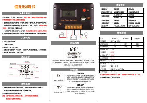
使用说明书安全使用建议1.本控制器为12V/24V自动适应,首次安装时,请确保电池有足够的电压,以便控制器能够识别为正确的电池类型。
2.将控制器尽量靠近电池安装,以避免电线过长造成压降,影响正常电压判断。
3.本控制器只适用于各种铅酸电池(包括开口,密封,胶体等),请勿使用于其它电池(包括锂电池,镍氢电池等)。
4.本控制器只能使用光伏板作为充电源,请勿使用直流或其他电源作为充电源。
6.本控制器运行的时候会发热,请注意将控制器安装在平整,通风良好的表面。
产品特点1.采用工业级主控芯片。
2.大屏幕LCD显示。
3.完整的PWM充电管理。
4.内置过流/短路保护,开路保护,反接保护,均为自恢复型,不损伤控制器。
5.双MOS防倒灌电路,超低发热量。
液晶显示系统连接1.将蓄电池正负极按图示接入控制器,控制器将会自动检测蓄电池电压。
2.将负载正负极按图示接入控制器,注意不要反接。
3.将太阳能板按图示接入控制器。
注意:请严格按照以上顺序进行接入,否则可能会损坏控制器。
拆卸顺序与接线顺序相反。
显示/操作如上图所示,用户可以从主界面直观了解到电池电压,电池容量,充电状态,放电状态等。
轻按按键一次可以打开或者关闭负载,或者在出现异常界面的时候,强制恢复正常程序。
异常界面高温保护本控制器内置高温保护程序,出现此界面即表示控制器已经过热,此时控制器会停机并等待温度降低后重新启动,用户应减小充放电电流,不要将控制器安装在密闭空间内,应该将控制器安装在通风良好的环境里。
低电保护本控制器内置低电保护程序,出现此界面即表示电池电压过低,此时控制器会切断负载输出并等待电池电压回升后才重新打开负载,用户应减小放电电流,并注意及时充电,以免伤害电池寿命。
故障指南异常现象可能原因解决办法阳光充足但不充电光伏板开路或反接重新连接好光伏板负载标识不亮模式设置错误重新设置电池电压太低重新充电负载标识慢闪负载过流减小负载功率负载标识快闪短路保护移除短路,自动恢复控制器不亮电池电压太低/反接更换电池/检查反接技术参数*红色字体标记电压仅对应12V系统,如使用24/48V系统,请X 2/4。
新代控制器伺服连接与设定手册V2.4

SYNTEC伺服连接与设定手册by :苏州新代技术中心date : 2011/11/25ver :2.4版本更新记录*如有修改请恕不另行通知目录一、台达系列连线及参数设置 (4)1 台达A系列: (4)2 台达B系列: (6)3 台达AB系列: (8)4 台达A2系列: (10)5 台达B2系列: (12)二、安川连线及参数设置 (13)1 安川二型系列: (14)2 安川五型系列: (16)三、三菱系列伺服接线与参数设定 (19)1 三菱J2S-A: (19)2 三菱J3-A: (22)3三菱MR-E: (25)四、松下系列连线及参数设置 (30)1 松下A: (30)2 松下A4: (32)3 松下A5: (34)五、华中伺服连线及参数设置 (36)1 华中HSV-160: (36)2 华中HSV-18D: (38)六、ESTUN伺服连线及参数设置 (40)1 ESTUN-PRONET: (40)2ESTUN-EDB: (42)七、SANYO伺服连线及参数设置 (44)1 SANYO-R: (44)2 SANYO-PY2: (46)八、杭州英迈克伺服连线及参数设置 (50)1 杭州英迈克: (50)九、东元伺服连线及参数设置 (52)1 东元伺服(TSDA): (52)2 东元伺服(TSDE): (55)十、迈信连线及参数设置 (57)1 迈信EP1: (57)2 迈信EP2: (59)3 迈信EP100: (62)一、台达系列连线及参数设置1 台达A系列:参数仅供参考P1-55=3001,最高转速2台达B系列:参数仅供参考3台达AB系列:参数仅供参考4台达A2系列:参数仅供参考5台达B2系列:参数仅供参考二、安川连线及参数设置1安川二型系列:参数仅供参考2 安川五型系列:参数仅供参考三、三菱系列伺服接线与参数设定1 三菱J2S-A:参数仅供参考2三菱J3-A:以下为供参考的建议参数值,基本参数一般不变,增益滤波器参数视不同的机台有所改变MR-J3伺服参数表(注:简称前面带有*的参数,设定后将电源断开,再重新接通电源,参数生效。
新代说明书
目录第一单元新代控制器面板操作说明 (2)1.1新代控制器面功能树状图 (2)1.2 屏幕部分 (3)1.3主功能界面 (4)1.3.1F1:機台設定 (5)1.3.1.1 F1:座標切換 (6)1.3.1.2 F2:1/2 座標 (6)1.3.1.3 F3:清除座標 (6)1.3.1.4 F4:相對座標全部清除 (6)1.3.1.5 F5:座標偏移量 (7)1.3.2F2:程式編輯 (8)1.3.2.1 F1:插入循環 (9)1.3.2.2 F2:刪除行 (9)1.3.2.3 F3:編輯循環 (10)1.3.2.4 F5:檔案編輯子功能 (11)1.3.2.5F7:圖形模擬 (15)1.3.2.6 F8:檔案管理 (17)1.3.4F4:執行加工 (19)1.3.4.1F1:座標顯示 (19)1.3.4.2F2:圖形調整 (20)1.3.4.3F3:MDI 輸入 (21)1.3.4.4 F4:加工參數設定 (22)1.3.4.5 F8:工作記錄 (23)1.3.5F5:警報顯示 (24)1.3.5.1 F1:現存警報 (24)1.3.5.2 F2:歷來警報 (24)第二单元机械操作面板说明 (25)2.1 第二面板操作功能說明 (25)2.1.1电源开 (25)2.1.2电源关 (25)2.1.3紧急停止 (25)2.1.4原点模式寻原点功能 (25)2.1.5手动运动模式 (25)2.1.6手动寸动模式 (26)2.1.7MPG寸动模式 (26)2.1.8自动加工模式 (26)2.1.9MDI加工模式 (27)2.1.10MPG模拟功能 (27)2.1.11单节执行 (27)2.1.12主轴控制 (28)2.1.13工作灯 (28)2.1.14加工液 (28)2.1.15程序暂停 (28)2.1.16快速归始 (28)2.1.17快速进给的速度 (28)2.2文字键说明: (29)第三单元使用新代控制器的方法 (30)3.1 原点复归 (31)3.2 手动功能(JOG ,INC_JOG ,MPG) (32)3.3 设定工作坐标(G54..G59) (33)3.4 开启档案(编辑/联网文件夹) (34)3.5 指定一个执行NC程序(自动) (35)3.6 刀具设定(G40/G41/G42 ,G43/G44/G49) (36)3.7 刀具长度量测(G43/G44/G49) (37)3.8 手动资料输入(MDI ) (38)3.9 图形模拟 (39)3.10在新代控制器下检查NC程序 (40)第四单元程序制作指令说明 (41)4.1G码指令一览表 (41)4.2M码指令说明 (42)第五单元新代控制器网络连接 (44)5.1网络设定 (44)5.2网络疑难问题解决方法 (47)5.3联网最重要的三点 (51)第一单元 新代控制器面板操作说明1.1 新代控制器面功能树状图座標切換1/2 座標清除座標相對座標全部清除設定工件座標系統機台設定F1插入循環刪除行編輯循環搜尋置換行數搜尋拷貝行插入行檔案編輯子功能快速定位教導直線切削教導圓弧教導取消圓弧中點教導刪除行教導步進連續放大縮小回復取消模擬參數設定圖形模擬開啟新檔拷貝檔案刪除檔案磁碟機輸入輸出至磁碟機RS232 輸入RS232 輸出檔案管理程式編輯F2圖形對話輸入F3座標顯示圖形調整MDI 輸入加工參數設定刀具設定工作表單執行加工F4現在警報歷來警報儲存警報警報顯示F5系統參數回到第一頁操作設定參數設定F6PLC I BitPLC O Bit PLC C BitPLC S BitPLC A Bit PLC Re gis te r PLC T ime r PLC Counte r PLC 狀態系統資料公用變數狀態軟體安裝系統備份本地語文安裝目前語文備份系統管理診斷功能F7操作指引F8CNC 銑床1.2 屏幕部分如下所示:本书面说明:(1)程式编号(2)标题(3)时间(4)日期(5)资料输入(6)提示(7)状态(8)功能键选择1.3主功能界面下图为新代控制器的主功能画面.新代控制器之操作,是利用屏幕下方之F1~F8功能键来操作,使用者仅须按下操作键盘上F1~F8之功能键即可进入对应的次功能:1.3.1F1:機台設定显示现在位置的各种坐标系统,并可用于相对坐标系统的重新设定.进入本书面请按下主功能画面下的“F1 機台設定”。
恒康20A无线控制器说明书

ENOCEAN 20A RELAY CONTROLLERPower Input: 100-277 VAC, 50/60 HzCat. No. WSP20-9DxDI-001-WSP20-00BWARNINGS AND CAUTIONS:• TO AVOID FIRE, SHOCK, OR DEATH; TURN OFF POWER at circuit breaker or fuse and test that power is off before wiring!• To be installed and/or used in accordance with appropriate electrical codes and regulations.• If you are unsure about any part of these instructions, consult an electrician.• This product is intended only for use indoors and in dry locations.NOTES:• For use with Leviton ® LevNet RF™ 902 MHz products.• It may be more convenient to link the transmitters to controllers prior to final installation.DESCRIPTIONUse the Relay Controller to control full circuit loads with the 20A Relay Receiver in an incredibly small form factor. The controller may be linked to self-powered wireless switches, wireless sensors, and/or central controllers to facilitate energy savings and automation with no new wires.EQUIPMENT NEEDED FOR INSTALLATION• Slotted/Philips Screwdriver • Wire Connectors • Electrical TapeLINKING INSTRUCTIONS The Controller must be powered on while linking. After linking, the Controller retains all settings in the event of power loss. Link up to 25 devices.SIMPLE LINKINGUse Simple Link Mode for common applications:1. HOLD the MENU button until the relay clicks (about 5 seconds), then release. The receiver will toggle a steady pattern indicating Simple Link Mode is active: — — — —2. TRANSMIT the Link Signal by triple pressing the top button on switches or single pressing the Link (or teach) button on sensors. Relay pauses in ON position for3 seconds when the link is created, then toggling resumes. Link additional transmitters (up to 25) as needed. (Relay pauses in OFF position for 3 seconds when the link is deleted.)3. WAIT 30 seconds for Link Mode to exit automatically (toggling stops).SIMPLE LINK MODE OPERATING BEHAVIOR• Manual Switch Control (top button ON / bottom button OFF, hold to dim ) : Link any switch.• Motion Sense Auto ON / Auto OFF: Link only Occupancy sensors.• M anual Switch ON / Motion Sense Auto OFF: Link both Occ Sensors & Switches.• Window/Door Sensor: Closed ON / Open OFF.• Key Card Control: Card in ON, Card out OFF.• Control Transmitter: ON and OFF.• Master Dimming Control: Link an Area Controller with 0-10V input as master.• Other Functionality: See instructions on page 2.ADDITIONAL FUNCTIONSTEST FUNCTIONPress and release the SELECT button to toggle Relay ON and OFF.SENSOR LINK TEST MODEAfter linking, press the Link button on a sensor 6 times to activate the Link Test Mode. Subsequent presses from any linked sensor will cause the relay to toggle confirming the sensor is linked and testing the reliability of wireless communications. Link Test Mode will time out after 60 seconds of no activity.CLEAR ALL LINKS1. Activate Simple Link Mode by holding the MENU button until the Controller starts toggling.2. Hold the SELECT button for 10 seconds to Clear All Links from the Controller.SELECTIVE LINK DELETIONTo remove one Link from Controller and leave others unaffected:1. HOLD the MENU button to activate Link Mode. The toggling output confirms Link Mode is active.2. TRANSMIT the Link Signal by triple pressing the top button on switches or single pressing the Link (or teach) button on sensors. Relay pauses in OFF position for 3 seconds when the link is deleted, then toggling resumes.3. WAIT 30 seconds for Link Mode to exit automatically (toggling stops).REPEATER MODERepeater function is DISABLED by default and may be enabled on specific controllers to extend the range by retransmitting all packets 1 or 2 times. Repeater mode may be changed using Advanced Setup instructions.Transmit - - -> Repeater 1x - - -> Repeater 2x - - -> ReceiveINSTALLATION1. W ARN IN G: TO AVOID FIRE, SHOCK, OR DEATH; TURN OFF POWER at circuit breaker or fuse and test that power is off before wiring!2. P LAN - Identify best mounting locations for receiver and transmitter. Perform range test to confirm operation prior to installation.3. C ON N ECT - Make connections to the Controller following wiring diagram and local electrical codes. Restore power.4. TEST - Press SELECT button to toggle output.5. L IN K Transmitters and Receivers following Linking Instructions below.COMPATIBLE DEVICES:WSC12-M9N WSD20-9Dx WSS0S-x9x WSTLT-9Dx WSWDR-H9W EEPS:A5-38-08 - non timed commands onlyF6-02-01, F6-02-02, F6-03-01, F6-03-02, F6-04-01A5-07-01, A5-07-02, A5-07-03D5-00-01, A5-30-01A5-06-02, A5-06-03FEATURES• Power consumption - save 70% over other wireless technologies.• L ong range - with a 50-150’ range, LevNet RF provides the longest reliable range in the industry.• Easy-to-use - programs in seconds; run zero switch-leg or traveler wires.• Increased memory - each unit stores up to 25 transmitter IDs; error checkingensures the receiver only responds to appropriate transmitters on all packet transfers.• Save energy - teach the receiver to respond to a LevNet RF sensor or teach all lights to respond to a single master switch.• C ontrol the way you want it - control the receiver with a variety of devices - wireless self-powered switches, sensors and more.• Simple wireless controls - single-pole, 3-way, and 4-way switches; architectural lighting control; motor control; and Manual-ON/OFF and Auto-OFF controls.• Built-in repeater - repeats wireless signals received for extended range, flexibility and reliability.CHOOSE THE OPTIMAL MOUNTING LOCATIONThe long term reliability and wireless performance of the Relay is strongly influenced by the mounting location. Choose a mounting location carefully. For best radio performance:• Straighten antenna out and away from metal.• C reate separation distance away from interfering electronics such as fluorescent tube ends, electronic transformers/power supplies, motors, etc.• Avoid mounting inside metal enclosures.• O bstructions of metal, concrete, and dense building materials will reduce the range. Mount higher and away from obstructions to maximize the range.• I nstallation above a hot fixture may result in overheating or melting. Confirm operating environment does not exceed temperature or humidity specs.• Site survey tools are available to help fine tune wireless communications.© 2016 Leviton Mfg Co., Inc.DI-001-WSP20-00BFor Technical Assistance Call: 1-800-824-3005 (U.S.A. Only) LIMITED 5 YEAR WARRANTY AND EXCLUSIONSLeviton warrants to the original consumer purchaser and not for the benefit of anyone else that this product at the time of its sale by Leviton is free of defects in materials and workmanship under normal and proper use for five years from the purchase date. Leviton’s only obligation is to correct such defects by repair or replacement, at its option. For details visit or call 1-800-824-3005. This warranty excludes and there is disclaimed liability for labor for removal of this product or re-installation. This warranty is void if this product is installed improperly or in an improper environment, overloaded, misused, opened, abused, or altered in any manner, or is not used under normal operating conditions or not in accordance with any labels or instructions. There are no other or implied warranties of any kind, including merchantability and fitness for a particular purpose , but if any implied warranty is required by the applicable jurisdiction, the duration of any such implied warranty, including merchantability and fitness for a particular purpose, is limited to five years. Leviton is not liable for incidental, indirect, special, or consequential damages, including without limitation, damage to, or loss of use of, any equipment, lost sales or profits or delay or failure to perform this warranty obligation . The remedies provided herein are the exclusive remedies under this warranty, whether based on contract, tort or otherwise.FOR CANADA ONLYFor warranty information and/or product returns, residents of Canada should contact Leviton in writing at Leviton Manufacturing of Canada Ltd to the attention of the Quality Assurance Department, 165 Hymus Blvd, Pointe-Claire (Quebec), Canada H9R 1E9 or by telephone at 1 800 405-5320.FCC COMPLIANCE STATEMENT Contains: SZV-STM300UThe enclosed device complies with Part 15 of the FCC Rules. Operation is subject to the following two conditions:(i.) This device may not cause harmful interference(ii.) This device must accept any interference received, including interference that may cause undesired operation. Any changes or modifications not expressly approved by Leviton could void the user’s authority to operate this equipment. This equipment has been tested and found to comply with the limits for a Class B digital device, pursuant to part 15 of the FCC Rules. These limits are designed to provide reasonable protection against harmful interference in a residential installation. This equipment generates uses and canradiate radio frequency energy and, if not installed and used in accordance with the instructions, may cause harmful interference to radio communications. However, there is no guarantee that interference will not occur in a particular installation. If this equipment does cause harmful interference to radio or television reception, which can be determined by turning the equipment off and on, the user is encouraged to try to correct the interference by one or more of the following measures:• Reorient or relocate the receiving antenna.• Increase the separation between the equipment and receiver.• C onnect the equipment into an outlet on a circuit different from that to which the receiver is connected.• Consult the dealer or an experienced radio/TV technician for help.IC COMPLIANCE STATEMENT Contains: 5713A-STM300UThis device complies with Industry Canada license-exempt RSS standard(s). Operation is subject to the following two conditions: (1) this device may not cause interference, and (2) this device must accept any interference, including interference that may cause undesired operation of the device.IMPORTANT! Any changes or modifications not expressly approved by the party responsible for compliance could void the user’s authority to operate this equipment.This Class B digital apparatus complies with Canadian ICES-003.TRADEMARK DISCLAIMER: Use herein of third party trademarks, service marks, trade names, brand names and/or product names are for informational purposes only, are/may be the trademarks of their respective owners; such use is not meant to imply affiliation, sponsorship, or endorsement.CERTIFICATION S: ETL: UL 60730 (U.S.), CSAC22.2#1405 (CANADA), UL 2043 (PLENUM) CE : IEC 60730, IEC6100045 (SURGE)FCC: SZV-STM300U (UNITED STATES) IC: 5713A-STM300U (CANADA)ADVANCED SETUPAdvanced Setup uses the Status LED to navigate a hierarchy of menus with blink patterns in one of 3 colors: Amber, Green, and Red. The relay output does not toggle while using Advanced Setup. Navigation overview:1. Hold MENU button 15 seconds until Status LED blinks Amber pattern.2. Press SELECT button to cycle through blink count options.3. Press MENU button to enter/save menu item.4. Hold MENU for 5 seconds to exit menu level.1 - ACTIVATE ADVANCED SETUPA. Hold MENU button 15 seconds until Status LED blinks Amber pattern.B. Jump to 2 Link - Mode or 3 Setup .2 - LINK MODE: AMBER MENU BLINKS 1-5 A. P ress SELECT button to cycle blink count and choose a Link Mode. Differentdevices may be linked in different modes. B. T ransmit Link Signal with fast triple press of switch button or single press of Linkbutton on sensors. Status LED will pause Green when link is added. If Link Signal is transmitted a second time, Status LED will pause Red indicating link is removed. C. O ptional - Press MENU button to see Green blinks indicating number of deviceslinked in the active mode. Red blink means no devices linked. Hold MENU button 5 seconds to return to Amber Menu.D. Wait 60 seconds or hold MENU button for 5 seconds to return to Operating Mode.3 - SETUP: AMBER MENU BLINKS 6-7 A. P ress SELECT button to cycle to Config (6 Amber blinks) options. B. Press MENU button to activate Green Menu.C. Press SELECT button to cycle through Green blink options.D. Press MENU button to activate Red Menu.E. P ress SELECT button to cycle through Red blink options or hold SELECT buttonto adjust level if applicable.F. Press MENU button to save selection.G. Hold MENU button for 5 seconds to return to Green Menu. H. Hold MENU button for 5 seconds to return to Amber Menu. I. H old MENU button for 5 seconds to exit to Operating Mode or power cycle orwait 60 seconds to exit.Amber Blink count OptionsHold MENU button 15 seconds until Status LED blinks Amber pattern. Press SELECT button to cycle through Amber blink counts. See Diagram.1Link Mode 1 Equal to Simple Link ModeSwitches: Rocker Mode (top button ON / bottom button OFF) triple press to link.Occ sensor: Manual ON / Auto OFF w/ switch linked, Auto ON/Auto OFF with no switch, 15 min default timeout. Window/Door Sensor: Closed ON / Open OFF. Control Transmitter: synchronize state. Central Command: synchronize state.2Link Mode 2Switches: Momentary button, triple press to link. Keycard: In ON / Out OFF, triple insertion to link.Occ Sensor: Auto ON / Auto OFF, 15 min default timeout.Window/Door Sensor: HVAC Mode, 5 min Off Delay, 5 min Minimum Off Time3Link Mode 3Switches: Toggle button, triple press to link. Occ Sensor: Auto ON / OFF, 5 min timeout.4Link Mode 4Switches: Scene button (recall specific dim level, adjust level with SELECT button), triple press to link/save.5Clear ModeSelective Clear: Triple press switch button or transmit Link Signal from sensor to selectively delete from all modes.Clear Links: Hold SELECT button for 5 seconds to clear all links. Clear All: Hold SELECT button for 15 seconds to restore factory defaults, solid red for 10 seconds confirms clear all success.6Config OptionsSee Table 2 "Config Options Green Menu."Table 1 - Amber MenuGreen Blink count Config Options Activate 6 blink Amber Menu, Press MENU to enter. Press SELECT button to cycle through Green blink counts. See Diagram.1Auto-OFF timeout 1: D isabled (default), 2: 5 min, 3: 10 min, 4: 15 min(Occ default), 5: 20m, 6: 25m, 7: 30m, 8: 60m, 10: Other 2Repeater 1: 1x repeating, 2: 2x repeating, 3: OFF (default).3Power up state 1: A uto (default), 2: State Memory, 3: Normally Closed,4: Normally Open.4Status reporting 1: A 5-38-08 (default), 2: A5-11-01, 3: disabled (when enabled transmits on change and every 2 +/minutes by default).5Invert relay 1: Relay asserted Closed (default). 2: Relay asserted Open: inverted logic.6Load type 1: AC loads only (default): arc suppression enabled.2: DC loads: arc suppression disabled.7SetDaylighting ThresholdSet the Daylighting Threshold between 10% and 90%. HoldSELECT button to adjust . LED blinks indicate Daylight Threshold setting: RED 1-9x.Table 2 - Config Options Green Menu (6 Amber Blinks)。
新代数控系统操作基础
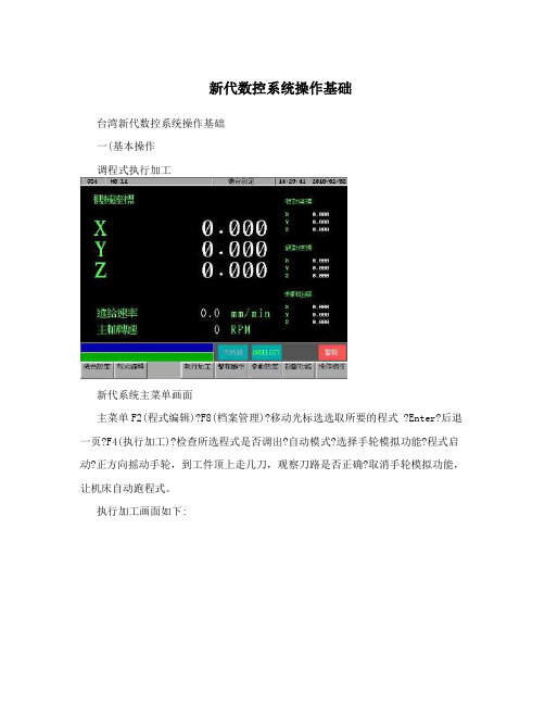
新代数控系统操作基础台湾新代数控系统操作基础一(基本操作调程式执行加工新代系统主菜单画面主菜单F2(程式编辑)?F8(档案管理)?移动光标选选取所要的程式 ?Enter?后退一页?F4(执行加工)?检查所选程式是否调出?自动模式?选择手轮模拟功能?程式启动?正方向摇动手轮,到工件顶上走几刀,观察刀路是否正确?取消手轮模拟功能,让机床自动跑程式。
执行加工画面如下:程式当前所当前使用的程式名使用的坐标系统从网络调程式主菜单F2(程式编辑)?F8(档案管理)?F8(网络档案输入)?移动光标选程式?确定?确定.加工中修改主轴转速主菜单?F4(执行加工)?F4(加工参数设定)?移动光标到主轴转速栏?输入所需的主轴转数?按Enter确认。
所出现的对话框如下图:在此输入所需的主轴转数分中功能主菜单F1(机台设定)?F5(设定工件坐标系统)?F5(分中功能)?在工件左侧铣一刀或碰一下?按PX1?在工件右侧铣一刀或碰一下按PX2.在工件前侧铣一刀或碰一下PY1按一下?后侧铣或碰按PY2?退页?G54(或G55,56……) ?F3(辅助坐标设定)自动对刀主菜单F1(机台设定)?F5设定工件座标系统)?F6(自动对刀)?自动模式?进给倍率打到100%—?F1(自动对刀起动)?待停止后?检查“数”是否抓到.备注说明:当测量模式选 1,单刀单工件:指无刀库,主轴上只能用一把刀,工作台上多数情况下只有一个待加工工件,使用一个工件坐标(如:G55)。
此时的落差(对刀仪与待加工工件表面的高度差),放在外部偏移Z轴坐标中。
当工件坐标号码设“0”时,对刀完成后,当前的刀长会记录在辅助点坐标Z轴中,此时还要退回到机台设定画面中,找到相应的工件坐标,按F3,Z轴做辅助点自动设定。
当工件坐标号码设“1”时,对刀完成后,当前的刀长会自动记录到工件坐标G54的Z轴中,无需再做辅助点坐标设定。
如此依次类推,设“2”对应到G55,设“3”对应到G56…。
新代说明书

SNCMillController ManualV3.0目录第一单元新代控制器面板操作说明 (2)1.1新代控制器面功能树状图 (2)1.2屏幕部分 (3)1.3主功能界面 (4)1.3.1 F1:機台設定 (5)1.3.1.1 F1:座標切換 (6)1.3.1.2 F2:1/2座標 (6)1.3.1.3 F3:清除座標 (6)1.3.1.4 F4:相對座標全部清除 (6)1.3.1.5 F5:座標偏移量 (7)1.3.2 F2:程式編輯 (8)1.3.2.1 F1:插入循環 (9)1.3.2.2 F2:刪除行 (9)1.3.2.3 F3:編輯循環 (10)1.3.2.4 F5:檔案編輯子功能 (11)1.3.2.5 F7:圖形模擬 (15)1.3.2.6 F8:檔案管理 (17)1.3.4 F4:執行加工 (19)1.3.4.1 F1:座標顯示 (19)1.3.4.2 F2:圖形調整 (20)1.3.4.3 F3:MDI輸入 (21)1.3.4.4 F4:加工參數設定 (22)1.3.4.5 F8:工作記錄 (23)1.3.5 F5:警報顯示 (24)1.3.5.1 F1:現存警報 (24)1.3.5.2 F2:歷來警報 (24)第二单元机械操作面板说明 (25)2.1第二面板操作功能說明 (25)2.1.1电源开 (25)2.1.2电源关 (25)2.1.3紧急停止 (25)2.1.4原点模式寻原点功能 (25)2.1.5手动运动模式 (25)2.1.6手动寸动模式 (26)2.1.7MPG寸动模式 (26)-0-SNCMillController Manual V3.02.1.9 MDI加工模式 (27)2.1.10MPG模拟功能 (27)2.1.11单节执行 (27)2.1.12主轴控制 (28)2.1.13工作灯 (28)2.1.14加工液 (28)2.1.15程序暂停 (28)2.1.16快速归始 (28)2.1.17快速进给的速度 (28)2.2文字键说明: (29)第三单元使用新代控制器的方法 (30)3.1原点复归 (31)3.2手动功能(JOG,INC_JOG,MPG) (32)3.3设定工作坐标(G54..G59) (33)3.4开启档案(编辑/联网文件夹) (34)3.5指定一个执行NC程序(自动) (35)3.6刀具设定(G40/G41/G42,G43/G44/G49) (36)3.7刀具长度量测(G43/G44/G49) (37)3.8手动资料输入(MDI) (38)3.9图形模拟 (39)3.10在新代控制器下检查NC程序 (40)第四单元程序制作指令说明 (41)4.1G码指令一览表 (41)4.2M码指令说明 (42)第五单元新代控制器网络连接 (44)5.1网络设定 (44)5.2网络疑难问题解决方法 (47)5.3联网最重要的三点 (51)SNCMillController ManualV3.0第一单元新代控制器面板操作说明1.1 新代控制器面功能树状图CNC銑床機台設定程式編輯圖形對話輸入執行加工警報顯示參數設定診斷功能操作指引F1 F2 F3 F4 F5 F6 F7 F8座標切換插入循環座標顯示現在警報系統參數PLC狀態1/2 座標刪除行圖形調整歷來警報回到第一頁PLCIBit 清除座標編輯循環MDI輸入儲存警報操作設定PLCOBit 相對座標全部清除檔案編輯子功能加工參數設定PLCCBit 設定工件座標系統刀具設定搜尋PLCSBit工作表單置換PLCABit行數搜尋PLCRegister拷貝行PLCTimer插入行PLCCounter教導系統資料公用變數狀態快速定位教導系統管理直線切削教導圓弧教導軟體安裝取消圓弧中點教導系統備份刪除行本地語文安裝圖形模擬目前語文備份步進連續放大縮小回復取消模擬參數設定檔案管理開啟新檔拷貝檔案刪除檔案磁碟機輸入輸出至磁碟機RS232輸入RS232輸出-2-SNCMillController ManualV3.01.2 屏幕部分如下所示:(1)(2)(3)(4)Screen(5)(7)(6)(8)本书面说明:(1)程式编号(2)标题(3)时间(4)日期(5)资料输入(6)提示(7)状态(8)功能键选择-3-1.3主功能界面下图为新代控制器的主功能画面.新代控制器之操作,是利用屏幕下方之F1~F8功能键来操作,使用者仅须按下操作键盘上F1~F8之功能键即可进入对应的次功能:1.3.1 F1:機台設定显示现在位置的各种坐标系统,并可用于相对坐标系统的重新设定.进入本书面请按下主功能画面下的“F1機台設定”。
ICS-17A和20A皮带秤安装说明书模板

ICSA A 1720系列电脑皮带秤目录第一章 绪言1.1 概述1.2 主要技术指标1.3 系统组成及工作原理1.4 开箱和检验 第二章 皮带秤的安装准则2.1 总则2.2 风和气候的影响2.3 输送机支架2.4 秤的安装位置2.5 重力式拉紧装置2.6 皮带糟形变化2.7 称重托辊第三章 安装第一部分 20A 的安装A3.1 概述A3.2 术语A3.3 安装位置A3.4 安装准备A3.5 称重桥架的安装A3.6 秤的托辊的安装A3.7 电气部分的安装第二部分 17A 的安装B3.1 概述B3.2 术语B3.3 安装位置B3.4 安装准备B3.5 称重桥架的安装B3.6 秤的托辊的安装B3.7 电气部分的安装第四章 维护4.1 概述4.2 日常维护4.3 故障排除第一章绪言1.1概述三原20A、17A系列电脑皮带秤,是在皮带输送系统中对散状物料进行连续计量的理想设备,具有结构简单、称量准确、使用稳定、操作方便,维护量小等优点,不仅适用于常规环境,而且适用于酸、碱、盐及大气腐蚀环境,广泛地应用于冶金、电力、煤炭、矿山、港口、化工、建材等行业。
说明书主要对20A/17A系列皮带秤系统的安装、运行、校准和维修等工作加以说明。
有关扩展板(打印和通讯)的安装、使用,在第六章积算器工作原理中也作了介绍和说明。
1.2主要技术指标1.2.1 系统性能²动态累计误差:20A皮带秤系统优于±0.5%17A皮带秤系统优于±0.25%²称量能力:6000t/h以下²皮带宽度:500~2200mm²皮带速度:0.1~4m/s²环境温度:秤架一20℃~60℃积算器一10℃~50℃1.2.2载荷传感器性能²非线性:小于额定输出的0.05%²重复性:小于额定输出的0.03%²滞后:小于额定输出的0.03%²激励:10VDC1.2.3速度传感器性能²频率范围:0~1.2KHZ1.2.4积算器性能²准确度:优于0.05%一15%²电源:220V ;50HZ±2%;25V A+10%²开口尺寸:285³140(宽³高)²输入重量输入:从一只或两只载荷传感器来的毫伏级信号;速度输入:从数字速度传感器传出的脉冲信号;²输出:激励电压输出:10±5%VDC;速度传感器输出:未稳压的24VDC;累重显示输出:八位带小数点,最小显示0.01t;流量显示输出:四位带小数点,单位为每小时吨;远程累计输出;相当于累重显示器上每个计数的1/1,1/10,1/100个数;电流输出:可选择4~20mA或0~20mA,电流输出,正比于流量。
LW520A卧式分离机安全操作规程
LW520A卧式分离机安全操作规程(1)开机前准备1、检查电机电源线有无破损2、检查刮板是否过松3、检查紧固螺栓是否松动4、检查主轴承的油嘴是否损坏5、检查电机电柜是否潮湿(2)开机1、打开主电源开关(在内部)2、电压不能超过400V3、待PLC显示屏显示主页时,点击“运行参数”进入运行界面4、按下电机启动按钮5、在电机升速过程中,检查电流、设备振动、噪音是否正常6、达到设定转速后、无异常准备进料7、刚开始进料时一定要少,一般开1/3进料阀8、出渣后检查电流,如果正常,把阀门开到一半9、不间断检查电流和出渣情况(3)关机1、关闭进料泵,关闭进料阀2、启动清洗按钮3、待降至清洗速度时,打开进油泵和进油阀:控制在1-2T/小时4、清洗15-30分钟,待出渣口不出渣即可5、关闭进油泵进油阀,按下点击关闭按钮1、经常检查电机电流LW520{理论值主电流:99A 副电流:20A{最佳状态运行时主电流:65A以下副电流:13A以下LW250{理论值主电流:60A 副电流:15A{最佳状态运行时主电流:50A以下副电流:10A以下2、每6小时加一次轴承润滑油(4)事故处理1、出渣口出油,立即关闭进油泵原因:1、进料量过大,减少进料量2、进油固含量下降,调整差速比(一般不能低于6)3、变频器不工作,检查保险丝和变频器2、报警停机原因:堵料立即停止进油泵,然后停机,手动盘动绞龙电机(1)、可以转动,把副变频器调到反转,开启副电机排渣20分钟,开启清洗按钮,进行清洗(2)、如果转不动,手动转动转鼓,直到可以转动,然后同上,(注意电机电流、振动、噪音)。
新代系统装机调试

请注意下列CNC参数必需依据机台实际状况个别调整:1.参数1221~1260 X/Y/Z背隙补偿2.参数941~960 X/Y/Z启动寻原点栅格功能。
(0→关闭、1→启动)3.CNC加工中心机配机步骤:一、重电回路OK。
1.先将控制器、屏幕、X/Y/Z伺服驱动器及主轴变频器电源线拔开再送电。
2.送电后确认各零件单元的入力电压正确后,才将电源送入各个单元。
3.送电后控制器需进入新代软件画面、伺服驱动器需要有显示讯息、主轴变频器需要有显示讯息。
二、安装PLC软体(D / APPCHI.STR / CNC.IL)及CNC参数(PARAM.DAT);相同机型有可以直接共用PLC、警报文件和参数等。
三、设定X/Y/Z伺服驱动器参数(见附件相关驱动器设定表格)。
四、设定主轴变频器参数。
五、X/Y/Z伺服马达动起来。
1.控制器诊断功能→系统数据40/41/42要等于24/25/26。
2.控制器画面显示移动1mm,床台需确实移动1mm。
六、X/Y/Z行程极限及原点讯号对应确认正确。
七、X/Y/Z寻原点动作需正常。
八、设定X/Y/Z软件行程极限、背隙补偿及判断寻原点栅格功能是否启动九、主轴动起来。
1.按主轴正转/反转按钮,主轴马达转向需正确。
2.主轴转速须正确。
十、测试操作面板功能。
十一、机床空运行看各驱动器负载率情况,及最大速度空运行,看驱动器是否会过载或报警类十二、试加工。
看机床加工尺寸精度,抖动,振动纹等系统参数设定归类:1、设定机床组装完毕后,相关伺服轴的机械参数对应的参数号为:9 ~ 386 范围,根据说明设定相关参数项目对应页面。
P3 ~ P52、设定机床运行速度等相关参数对应的参数号为:401 ~ 641 范围,根据设定说明进行设定对应页面。
P6 ~ P83、设定机床加工效果的参数对应参数号为:401 ~ 408 范围,同时各轴单独也要调整;对应页面。
P64、设定回原点的相关参数对应参数号为:821 ~ 1246 范围,根据各项说明进行设定对应页面。
新代数控说明书
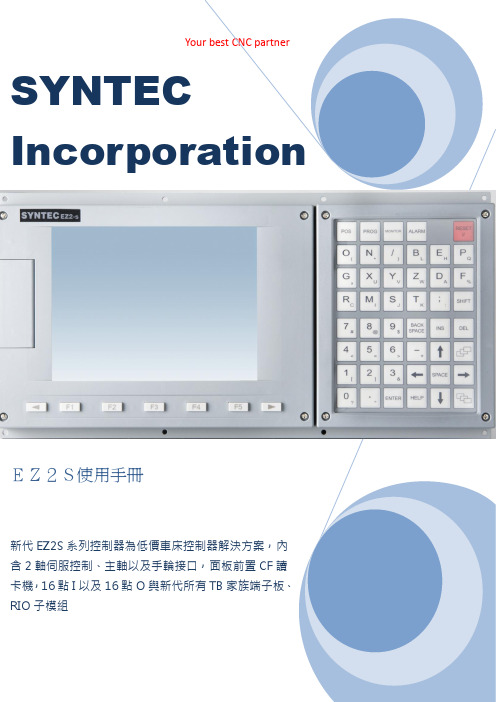
I n d e x產品規格 (3)產品機構 (4)機構尺寸圖(E Z2S) (4)板金開孔圖(E Z2S) (4)產品外觀圖(E Z2S) (5)E Z2S C O N N E C T E R介紹 (6)E Z2S接線示意圖 (7)I N:X1接腳定義&電氣介面 (8)O U T:Y1接腳定義&電氣介面 (9)H K接腳定義&電氣介面 (10)P1~P2接腳定義&電氣介面 (11)M P G接腳定義&電氣介面-1 (12)M P G接腳定義&電氣介面-2 (13)主軸接腳定義&電氣介面-1 (14)主軸接腳定義&電氣介面-2 (15)新代E Z S E R I E S數控系統規格 (16)服務據點 (17)S Y N T E C C N CE Z2S e r i e s產品規格新代ES系列控制器為低價車床控制器解決方案,內含2軸伺服控制、主軸以及手輪接口,面板前置CF讀卡機,16點I以及16點O與新代所有TB家族端子板、RIO子模組2軸伺服定位控制接口1個主軸Encoder接口,內含5V輸出1個手輪專用接口,內含A+.A-.B+.B-與外掛式手輪DI點與5V輸出面板前置cf card讀卡機輸入點數:16點(牛角接頭)輸出點數:16點(牛角接頭)第二面板專用接口(牛角接頭)外型尺寸:400mmx280mm後半部重新設計產品機構機構尺寸圖(EZ2S)板金開孔圖(EZ2S)產品外觀圖:(EZ2S)Top view Bottom ViewE Z2S C o n n e c t e r介紹P1、P2:伺服定位控制接口(D型15P)Spindle ENC:主軸ENCODER接口(D型15P)Spindle Command:主軸命令接口(歐規端子)MPG:手輪Encoder接口(D型15P)X1:輸入接口(20P牛角接頭)Y1:輸入接口(20P牛角接頭)HK:面板輸出入接口(26P牛角接頭)A、B:CF卡插槽Ethernet:網路線插孔KEYBOARD:PS/2鍵盤接頭E Z 2S 接線示意圖I N:X1接腳定義&電氣介面外部輸入介面X1在EZ2S 控制器,有一組外部輸入接頭,可直接接至各種檢測感測器(如近接、微動開關等..)配合TB16IN使用,可簡化配線。
控制器安装指南说明书

INSTALLATION GUIDE TO CONTROLSStep ThreeStep Four Panel DIN Rail Mounting The controller may be mounted by either a back panel using two screws through mounting holes located at the corners of the controller or by snapping the controller on 35 mm DIN Rail.+R E L A Y 1R E L A Y 2PO W E RI N V E R T I N V E R T D E L A Y--+--D E L A Y ONOFF LA T CHI N P U T 1I N P U T 2A I N P U T 2B137254472568669991. Power indicator: This green LED lights when AC power is ON.2. Relay indicator: This red LED will light whenever the controller energizes the relay, in response to the proper condition at the switch input and after the time delay.3. AC Power terminals: Connection of 120 VAC power to the controller. The setting may be changed to 240 VAC if desired. This requires changing internal jumpers; this is covered in the Installation section of the manual. Polarity (neutral and hot) does not matter.4. Relay terminals (NC, C, NO): Connect the device you wish to control (pump, alarm etc.) to these terminals: supply to the COM terminal, and the device to the NO or NC terminal as required. The switched device should be a noninductive load of not more than 10amps; for reactive loads the current must be derated or protection circuits used. When the red LED is ON and the relay is in the energized state, the NO terminal will be closed and the NC terminal will be open.5. Time delay: Use potentiometer to set delay from 0.15 to 60seconds. Delay occurs during switch make and switch break.6. Input indicators: Use these LEDs for indicating Flow or No-Flow status of switch. For NC wiring, an Amber LED indicates No-Flow and no LED indicates Flow. For NO wiring, an Amber LED indicates Flow and no LED indicates No-Flow.7. Invert switch: This switch reverses the logic of the relay control in response to the switch: conditions that used to energize the relay will now de-energize the relay and vice versa.8. Latch switch (TDC): This switch determines how the relay will be energized in response to the two sensor inputs. When LATCH is OFF, the relay responds to switch Input 2A only; when LATCH is ON,the relay will energize or de-energize only when both switches (2A and 2B) are in the same condition (Flow or No-Flow). The relay will remain latched until both switches change conditions.9. Input terminals: Connect the switch wires to these terminals:Note the polarity: (+) is a 24 VDC, 50 mA power supply (connected to the red wire of a Dwyer flow switch), and (-) is the common ground path from the switch (connected to the black wire). Also, the (S) is a 14VDC, 25 mA supply (connected to the white wire). If polarity between the red and black wires is reversed, the switch will change from NC to NO. 3.475" 2.2".275".225"35 m m D I N R a i l Note: Always install the controller in a location where it does not come into contact with liquid.Connecting switches to input terminals:Please note a difference between Dwyer flow switches (N-channel and P-channel). Use only the N-Channel switches with the TDC series of controller. Wire the Red wire to the (+) terminal and the Black wire to the (-) terminal. Wire the White wire to the (S). See the illustration below to indicate wiring for your switch. Reversing Red and Black wire will change switch from NC to NO. Note: connect the Shield wir e on the Flow switch to the GND terminal if required.LED Indication Use LED's located above the input terminals to indicate whether the switch is in a Flow or No-Flow state. With the flow switch wired NC, the Amber LED indicates No-Flow and no LED indicates flow. Wiring the switch NO (reversing the Red and Black wires), the Amber LED indicates Flow and no LED indicates No-Flow.NO Wiring Amber NO Wiring OFFINPUT1I N P U T 2A I N P U T 2B W h i t e B l a c k FT10-XX02GT10-XX02NC Wiring FT10-XX02GT10-XX02NO Wiring O N O F F L A T C H R e d W h i t e R e d B l a c k INPUT 14 VDC 25 mA Max.( - )( S )GND 24 VDC 50 mA Max.( + )NC Wiring Amber NC Wiring OffINSTALLATIONTROUBLESHOOTING Step FiveStep Six VAC Power Input WiringNote: Polarity does not matter with the AC input terminalController Logic For all controllers, please use the following guide to understand the operation of the Dwyer TDC1/TDC2 controllers.1.Make sure the Green power LED is On when power is supplied to the controller.2.For NC switch wiring, the input LED's on the controllers will be Amber when the switch reads No-Flow and Off when the switch reads Flow.3.The input LED will always respond to its corresponding relay LED.With invert Off, the relay LED will be On when the input LED is On and Off when the input LED is Off. With invert On, the relay LED will be Off when the input LED is On and On when the input LED is Off.4.The relay may be wired either NO or NC. The normal state of the relay is when its LED is Off. With the LED On, the relay is in the energized mode and all terminal connections are reversed.5.TDC model only, Latch ON operation: When both input LED's are ON, the relay will be energized (red LED On). After that, if one switch input turns Off, the relay will remain energized. Only when both switch LED's are Off will the controller de-energize the relay.The relay will not energize again until both switch LED's are ON.Reversing Invert switch will reverse logic. See the Logic Chart below for further explanation.Relay Input WiringThe controllers use dry contact Single Pole DoubleThrow (SPDT) relays rated at 250 Volts AC, 10Amps, 1/2 Hp. The terminals are labeled NormallyOpen (NO), Common and Normally Closed (NC).Below shows four examples of basic wiring:Ground Neutral Hot + --GroundNeutralHot+--POWER120 VAC, 50 - 60 Hz AC 240 VAC, 50 - 60 Hz AC GNDAlarm Contact @ No-Flow Pump Open @ No-FlowNO NCRELAY OUTPUT 250 VAC, 12 A, 1/2 Hp C + --+ --+--+ --Note: The invert is switched between the Alarm and Pump Wirings.Normally Open Relay Wiring Normally Closed Relay Wiring+ --+ --+--+ --Note: The inver t is switched changes between Nor mally Open and Normally Closed.Changing from 120 to 240 VACRemove the back panel of the controller and gently slide the printed circuit board from the housing. Use caution when removing the PCB.Located jumpers JWA, JWB and JWC on the PCB. To change to 240VAC, remove jumpers from JWB and JWC and place a single jumper across JWA. To change to 120 VAC, remove jumper JWA and place jumpers across JWB and JWC.J W B JW C J WA J W B JWC J WA120 VAC 240 VACInvert Off Input A ON OFF InputB No Effect No Effect Relay ON OFF Invert ON Input A ON OFF InputB No Effect No Effect Relay Off On Invert Off Input A ON OFF ON OFF InputB ON ON OFF OFF Relay ON No Change No Change OFF Invert ON Relay Off No Change No Change OnInput A ON OFF ON OFF InputB ON ON OFF OFF — +Latch Off On Off — +On Off Latch Off — +On Off — +On Off Latch ON Latch ON Relay Latch Logic ChartSPECIFICATIONSStep TwoSupply voltage:120 / 240 VAC, 50 - 60 Hz.Consumption:5 Watt Sensor supply:13.5 VDC @ 100 mA Relay type:TDC1:(1) SPDT TDC2:(1) SPDT, (1) Latched SPDT Relay load:250 VAC, 10A, 1/2 hp.Relay mode:Selectable, NO or NC Time delay:0 to 60 seconds LED indication:Sensor, relay & power status Fail safety:Power fail-safe Temperature range:F: -40 to 158 C: -40 to 70 Enclosure rating:Panel or 35 mm DIN Rail (EN 50 022)Enclosure material:Polypropylene (U.L. 94 VO)Certificate number:LR 79326-3 (CSA/NRTL)Dimensions 2.7"1.8"R E L A Y 1R E L A Y 2P O W E R I N V E R T I N V E R T D E L AY D E L AY ONOFF LATCH I N P U T 1I N P U T 2A I N P U T 2B+—+—3.9"3.6"3.1"Make a Fail-Safe System:Design a fail-safe system that accommodates the possibility of relay or power failure. If power is cut off to the controller, it will de-energize the relay. Make sure that the de-energized state of the relay is the safe state in your process. For example, if controller power is lost, a pump will turn off if it is connected to the Normally Open side of the relay.While the internal relay is reliable, over the course of time relay failure is possible in two modes: under a heavy load the contacts may be “welded”or stuck into the energized position, or corrosion may build up on a contact so that it will not complete the circuit when it should. In critical applications, redundant backup systems and alarms must be used in addition to the primary system. Such backup systems should use different sensor technologies where possible.While this manual offers some examples and suggestions to help explain the operation of Dwyer products, such examples are for information only and are not intended as a complete guide to installing any specific system.LR79326 -3Power SupplyRefer to the instructionmanual for installationinstructions.120/240 VAC, 50 - 60 Hz5 Watt250 VAC, 10 A, 1/2 HpMaximum Relay RatingNRTL-C TDC1 Faceplate Approval Label + --+--+--TDC2 FaceplatePower Supply Latch / Invert LogicTime DelayACACGNDSensor Input A*Sensor Input B*Relay ("Relay 2" in LC82)Relay ("Relay 1"in LC82)NCCNOSensor Input 1Latch / Invert Logic Time Delay NCCNO (+)(-)S+ - S + - S Part Number Information:Part #Mat'l Description TDC1PP Flow/No-Flow Controller TDC2PP Dual Flow/No-Flow Controller Functional Diagram。
