YAV USB接口采集卡二次开发即DLL使用手册USB6000
基于LabVIEW和USB接口数据采集器的设计
基于LabVIEW和USB接口数据采集器的设计张青春【摘要】For engineering measurement for data acquisition device's actual need, this paper used LabVIEW graphical development software, high-precision and high-speed data acquisition device MAX197, AT89C52 microcontroller and USB control chip CH372,achieved the 8 channels 12 -bit data acquisition, 1 channel 8 -bit D/A output. And it displays the temperature detected, A/D maximum sampling frequency can be 100 kHz. This data collector has the high performance-to-price ratio,it can be applied widely.%针对工程测量对数据采集器的实际需要,采用LabVIEW图形化开发软件、高精度高速度的MAX197数据采器、AT89C52单片机和CH372 USB 控制芯片,实现8路12位数据采集、1路8位D/A输出,同时具有温度检测显示功能,A/D最高采样频率可达100 kHz.该数据采集器具有较高的性价比,可以推广应用.【期刊名称】《仪表技术与传感器》【年(卷),期】2012(000)012【总页数】3页(P32-34)【关键词】LabVIEW;USB接口;控制芯片CH372;数据采集【作者】张青春【作者单位】淮阴工学院电子与电气工程学院,江苏淮安223003【正文语种】中文【中图分类】TP2740 引言随着电子信息技术的发展,数据采集在智能仪器、工业自动化和工程技术领域有相当广泛的应用。
usb数据采集卡V52_32使用说明书
usb数据采集卡V52_32使⽤说明书USB 数据采集卡V5.2_32使⽤⼿册新郑市恒凯电⼦科技有限公司2016/3USB2.0总线AD 采集模块 32路同步单端输⼊16位 20KHz AD,192K FIFO 缓冲 2路12位0—10V 量程DA 输出16路单向输⼊⼝/16路单向输出⼝在开始使⽤前请仔细阅读下⾯说明检查打开包装请查验如下:USB数据采集卡V52_32⼀块配套电源及USB数据线安装将数据采集卡插⼊主机的任何⼀个USB2.0插槽中并将外部的输⼊、输出线连好。
如果主机USB电源供应能⼒差,请连接附送的电源。
保修本产品⾃售出之⽇起⼀年内,⽤户遵守储存、运输和使⽤要求,⽽产品质量不合要求,凭保修单免费维修。
因违反操作规定和要求⽽造成损坏的,需缴纳器件费及相应的运输费⽤,如果板卡有明显烧毁、烧糊情况原则上不予维修。
如果板卡开箱测试有问题,可以免费维修(限购买板卡10天内)。
软件⽀持服务⾃销售之⽇起提供6个⽉的免费开发咨询。
(如有刊误,敬请批评指正!)⽬录⽬录 (2)⼀、USB数据采集卡V52_32说明 (4)USB数据采集卡V52_32板简介 (4)特点: (4)主要特点、性能: (5)AD部分: (5)DA输出 (5)开关量输⼊输出 (5)软件⽀持: (6)其他特性 (6)⼆、原理说明 (7)2-1:模拟输⼊输出接⼝ (7)AD数据排列 (7)AD数据转换 (7)内部定时器时钟与外部时钟 (7)触发开始采样 (8)过采样及相关说明 (8)2-2:开关量部分的原理: (10)2-3:模拟输出DA (10)三、安装与连接 (11)3-1:安装 (11)关于USB (11)USB延长线 (11)3-2:信号连接注意事项 (11)3-3:连接器插座定义 (12)16 DIN定义: (12)16 DOUT定义: (13)3-4:配套端⼦板 (13)四、软件 (15)4-1:软件安装与说明 (15)软件说明 (15)驱动安装 (16)测试软件安装 (19)4-2:接⼝函数说明 (22)设备操作函数 (22)AD操作函数 (23)DA操作函数 (25)单向开关量输⼊操作函数 (25)单向开关量输出操作函数 (26)4-3:VC程序编程说明 (28)4-4 Labview程序编程说明 (29)⼀、USB数据采集卡V52_32说明USB数据采集卡V52_32板简介USB数据采集卡V5.2_32是⼀款基于USB总线的⾼性能多功能数据采集卡,具有32路单端16位⾼速同步模拟信号采集(最⾼同步采样速率50KSPS,同步采样即每通道都是50KSPS)、2路12位模拟信号输出(只有单次低速输出模式)、16路数字信号单向输⼊/16路数字信号单向输出。
USB数据采集卡的使用流程 (2)

USB数据采集卡的使用流程1. 引言USB数据采集卡是一种常用的设备,用于连接计算机与外部传感器、仪器等设备,将采集到的数据传输给计算机进行处理和分析。
本文将介绍USB数据采集卡的使用流程。
2. 准备工作在使用USB数据采集卡之前,需要进行一些准备工作,主要包括: - 确定所需采集的数据类型和频率,以便选择合适的USB数据采集卡。
- 下载并安装USB数据采集卡的驱动程序,确保能够正常连接并识别设备。
- 准备相应的传感器、仪器等设备,确保能够接入USB数据采集卡。
3. 连接USB数据采集卡连接USB数据采集卡需要按照以下步骤进行: 1. 将USB数据采集卡插入计算机的USB接口。
2. 等待计算机自动识别设备并安装驱动程序。
如果计算机没有自动安装驱动程序,可以手动安装,通常可以从USB数据采集卡的官方网站或光盘中获取驱动程序。
3. 检查USB数据采集卡的连接状态,确保设备正确连接到计算机。
4. 配置软件设置配置USB数据采集卡的软件设置需要按照以下步骤进行: 1. 打开USB数据采集卡的软件界面,通常可以从桌面上的快捷方式或开始菜单中找到。
2. 在软件界面中选择相应的数据采集卡设备,确保与实际连接的设备对应。
3. 根据所需的数据类型和频率,设置数据采集的参数,例如采样率、增益等。
4. 配置数据存储位置和文件格式,可以选择保存为文本文件、CSV文件或其他格式。
5. 检查软件设置是否正确,确保能够正常采集数据。
5. 数据采集进行数据采集需要按照以下步骤进行: 1. 确保所有设备连接正常,传感器或仪器的信号源正确接入到USB数据采集卡。
2. 点击软件界面上的开始采集按钮,开始采集数据。
3. 观察数据采集的过程,确保数据的准确性和稳定性。
4. 在需要暂停或停止采集时,点击软件界面上的相应按钮进行操作。
5. 保存采集到的数据到指定的文件位置,以便后续处理和分析。
6. 数据处理和分析采集到的数据可以通过一些数据处理和分析软件进行进一步的处理和分析,常见的软件包括Matlab、Python等。
接口使用手册V1.2

//层参数结构体定义
Typedef struct LAYER_PARA
{
int
nCount;
// 打标次数
double dbMarkV;
//矢量打标速度(mm/s)
double dbJumpV;
//矢量空跳速度(mm/s)
double dbQFreq;
//Q 频(KHz)
double dbQRls;
pszFileName:打标文件完整路径及名称。
6、HS_GetDocList 语法:int HS_GetDocList(TCHAR szDocList[][50], int* pCount) 作用:获取当前所有已打开文档列表,文档名不允许超过 50Bytes。 参数描述:
szDocList:文档列表指针。 pCount:传入缓冲区数组大小,处理完成后返回实际获取文档数。
二次开发软件接口使用手册 V1.2
HANS 二次开发软件接口使用手册(V1.2)
版本号
1.0 1.1
1.2
修订日期
2010.10.10 2010.12.01
2011.02.16
修订人
钟四化 杨秀锋
钟四化
变更记录
初版 根据富士康需求,增加 Unicode、取错误接口. 根据定制部门的需求、增加对象及文档操作接口,提 供更丰富的应用
二、 返回值及结构体定义
所有函数返回值均为一个整形的通用错误码,码值定义如下
#define HL_ERR_SUCCESS
0 //成功
#define HL_ERR_PROGRUN
1 //另一个程序在运行
#define HL_ERR_PATH
2 //路径不正确
#define HL_ERR_FAILOPEN
USB数据采集卡信号采集卡对照表

亚为科技硬件对照表YAV-201604武汉亚为电子科技有限公司采集模块系列USB ADIO信号采集卡USB 2AD plus信号采集卡•USB通信,免驱,无需其他电源•2路AI,2路DI,2路DO控制•AI默认0-10V(可定制0-20MA/0-5V/0-15V/0-20V/0-30V/0-60V)•AI分辨率12Bit,每通道采样率可达5Kbps•两路5V电源输出•-30~70℃宽范围工作•可供蜂鸣器、继电器、通道开关、量程电路等切换使用•USB通信,免驱,无需其他电源•2路AI,2路DI采集,2路DO控制•AI默认0-10V(可定制0-20MA/0-5V/0-15V/0-20V/0-30V/0-60V)•DI输入通道: 2路;电平兼容TTL或CMOS•输出D0通道:2路,电平:5V(可驱动5V继电器)USB ADIO+信号采集卡YAV2AD信号采集卡•USB通信,免驱,无需其他电源•2路AD采集,2路DI采集,2路DO控制•AI默认-10-10V(可定制±5V/±15V/±20V/±30V/±60V)•分辨率12Bit,采样速率5Kbps•两路5V电源输出•-20℃— 70℃宽范围工作•可供蜂鸣器、继电器、通道开关、量程电路等切换使用•RS232通信•2路AD采集,2路DI采集,2路DO控制•AI默认0-10V(可定制0-20MA/0-5V/0-15V/0-20V/0-30V/0-60V)•分辨率12Bit,传输速率可达30bps•两路5V电源输出•-20℃— 70℃宽范围工作•可供蜂鸣器、继电器、通道开关、量程电路等切换使用USB ADIO Pro信号采集卡WIFI 2AD信号采集卡•USB通信,免驱,无需其他电源•2路AD采集,2路DI/PWM采集,2路DO控制•AI默认-10-10V(可定制±5V/±15V/±20V/±30V/±60V)•分辨率12Bit,采样速率5Kbps•两路5V电源输出•DI/PWM管脚可以自定义,可计数计频•-20℃— 70℃宽范围工作•可供蜂鸣器、继电器、通道开关、量程电路等切换使用•RS232通信•支持802.11b/g/n无线标准•12V/5V电源供电•2路AI,2路DI,2路DO控制•AI默认0-10V(可定制0-20MA/0-5V/0-15V/0-20V/0-30V/0-60V)•DI输入通道:2路,TTL或CMOS•输出D0通道:2路,电平:5V•预留2计数器/频率计接口•支持无线和远程访问USB 8AD信号采集卡YAV 8AD信号采集卡•USB通信,免驱,无需其他电源•8路AI采集,2路DI采集,1路5V电源输出•8路单端0-10V模拟输入•AI默认0-10V(可定制0-20MA/0-5V/0-15V/0-20V/0-30V/0-60V)•分辨率12Bit,采样速率2Kbps •RS232/RS485串口通信•8路0~10V AI输入,可以方便的连接上百种传感器•AI默认0-10V(可定制0-5V/0-15V/0-20V/0-30V/0-60V/0-20MA/0-5mA/0-40mA)•分辨率12Bit,波特率9600 •地址,波特率可修改USB 8AD plus信号采集卡YAV 8AD-16高精度采集卡•USB通信,免驱,无需其他电源•8路AI采集。
avm-usb2使用手册说明书
OPERATION MANUAL FOR AVM-USB22016/04/11Watec Co., Ltd.REVISION HISTORYRevision Date Changed1.0 2016.3.7 1st Release2.0 2016.4.11 2nd Release*Renamed the jig board to “AVM-USB2”CONTENTSREVISION HISTORY (1)INTRODUCTION (3)Including (3)Support camera (3)Equipment (3)PC REQUIREMENTS (3)USB CABLE REQUIREMENT (3)INSTALL (4)UNINSTALL (4)DESCRIPTION OF THE APPLICATION (5)Menu (6)File (7)Tool (8)Help (9)Connection Mode (6)DISCONNECTED MODE (6)CONNECTED MODE (6)Parameter Setting (10)AE (10)BLC (11)SETUP (12)BRIGHTNESS (13)WB (14)ENHANCE (15)MIRROR (16)COLOR/MONO (17)GAMMA (18)ERROR MESSAGE (19)OPERATION PROCEDURE (20)Caution (20)INTRODUCTION IncludingAVM-USB2 1pcSupport camera WAT-240E/FS model onlyEquipment PC REQUIREMENTS OS :Windows 7, Windows 8/8.1, Windows 10 USB :USB standard 1.1, 2.0, 3.0 USB CABLE REQUIREMENTCABLE TYPE :A (PC side) - micro-B ([AVM-USB2] side) CABLE LENGTH :Less than 5m micro-B (Camera)INSTALLUnzip AVM-USB2_ControlSoftware_(R)_E120.zipAVM-USB2_ControlSoftware_(R)_E120.exeSLABHIDDevice.dllSLABHIDtoSMBus.dllei_agc_max.csvinitial_rom.csvshut_agc_max.csvinitial.txt …WAT-240E/FS factory default fileUNINSTALLDelete unzipped files.DESCRIPTION OF THE APPLICATIONMenu Connection ModeParameter settingConnection ModeDISCONNECTED MODENot connected to the camera. The software starts up in this mode.It will not be reflected in the camera if you change the parameters.You can use to create a parameter file without a camera connection. When you press the [disconnected] button, and then move to [connected] mode.CONNECTED MODEIt connected to the camera.It will be reflected in the camera if you change the parameters.When you press the [connected] button, and then move to [disconnected] mode.FileLoadLoad the parameter file.In the case of the CONNECTED MODE, the parameter settings are sent to the camera and software window.In the case of the DISCONNECTED MODE, the parameter settings are sent to the software window only.SaveSave the parameters on the current software window to a file.ExitExit this software.Initialize EEPROMRewrite the parameters of the camera to the factory default settings.All ROM writeWrite the parameters on the current software window to the connected camera.All ROM readRead from the parameters on the connected camera to the current software window.VersionShow the version of this software.Parameter SettingAESet the exposure mode.E.I + AGCAdjust the exposure with the electronic shutter and the automatic gain control. The maximum electronic shutter speed and the maximum gain can be selected.SHUT + AGCAdjust the exposure with fixed electronic shutter and the automatic gain control. The electronic shutter speed can be selected in OFF or FL. The range of the maximum gain can be selected.SHUT. + MGCFixed exposure mode.The electronic shutter speed and the gain can be selected arbitrarily.BLC Select the backlight compensation mode.■:Weighted Area. BLC LEVEL Adjust a compensation level.When the value is increased, the correction becomes stronger. OFF Center Default-VCenter+UnderUnderSETUPBRIGHTNESS100IREPreset [100IRE]75IREPreset [75IRE]ManualSelect brightness level manually.WBSet the white balance mode and tuning the R and B gain.ATWThe RGAIN and the BGAIN will be controlled automatically by camera.3200KUse for the Incandescent light bulb.4400KUse for the reddish fluorescent lamp.5100KUse for the bluish fluorescent lamp.8200KUse for the extremely bluish lamp.RGAIN/BGAINIn the mode of non- ATW, you can fine-tune the RGAIN and BGAIN.ENHANCESetting for the edge enhancement of vertical and horizontal directionsOFFSOFT (H/V)NORMAL (H/V) : DefaultHARDMIRRORSet the mirror image modeOFF : Default HorizontalVerticalHorizontal / VerticalCOLOR/MONOColorMonochromeBurst ONIf checked, Output a monochrome video signal with the color burst.GAMMA0.45Correct with a gamma of about 0.45 for CRT gamma 2.2.0.6Correct with a gamma of about 0.6.1.0No correction (linear)ERROR MESSAGEMESSAGE SOLUTION AVM-USB2 was not detected. Please check the connection of the USB cable.Multiple AVM-USB2 have been detected. Please connect only one.Unable to connect to AVM-USB2 and the camera. Please re-check the connection between the camera and AVM-USB2.OPERATION PROCEDURE1. How to Connect the Camera(1) Turn on the camera.(2) Connect AVM-USB2 and the camera.(3) Connect the PC and AVM-USB2.2. How to Disconnect the Camera(1) Make sure the power supply to the camera is off.(2) Disconnect the camera from AVM-USB2. Caution20。
YAV USB 采集卡二次开发即 DLL 使用手册说明书

YAV USB接口采集卡二次开发及DLL使用手册武汉亚为电子科技有限公司2020.05USB60001目录版本说明 (3)64位开发平台使用方法 (3)函数说明 (3)查找设备FindDevice (3)打开设备OpenYavDevice (4)读取数据GetYavData (4)配置设备SetYavParam (5)单次读取数据GetYavOnce (6)单次设置数据SetYavOnce (7)获取传感器数据YavSencer (7)获取感应器状态YavDI (7)关闭设备CloseYavDevice (8)配置命令 (9)加载流程 (11)多卡同步使用 (12)SDK及例程 (13)labview例程 (13)VC例程 (13)C#例程 (13)Matlab例程 (18)Delhpi例程 (18)其他平台例程 (19)23YAV USB 接口采集卡 二次开发及DLL 使用手册武汉亚为电子科技有限公司版本说明版 本 号:ADIO86.dll(32位开发平台)/ADIO64.dll(64位开发平台),V20180115适用范围:带有YAV 标识,或者武汉亚为电子科技有限公司产品标注,且具备USB (包括但不限于方口USB 、Micro USB )通信功能的采集卡,均可利用本指南。
特别声明:该指南适应于2017年9月1日之后YAV 采集卡64位开发平台使用方法YAV USB 接口的采集卡,无需安装驱动,可利用ADIO86.dll 与其他开发平台产生数据交互,dll 基于VS2010开发。
部分操作系统加载dll 时出错,需msvcr100d.dll 、msvcr120d.dll 配合使用,直接放ADIO86.dll 同文件夹下即可,如果是64位开发平台(注意:64位操作系统如果用的是32位开发平台,依然需要使用ADIO86版本),可ADIO64.dll 改名为ADIO86.dll ,替换并重启软件。
YAV 串口采集卡二次开发通信指令即Mobbus RTU(寄存器)手册DAM7000
YAV串口采集卡二次开发ModbusRTU指令使用说明
DAM7000
武汉亚为电子科技有限公司
2018.01
YAV串口采集卡二次开发
Modbus RTU指令使用说明
版本号:V201708
适用范围:带有YAV标识,或者武汉亚为电子科技有限公司产品标注,且具备串口(包括RS232/RS485或具备Modbus RTU功能的无线或者网口)接口的采集卡,均可利用本指南。
特别声明:该指南仅适应于2017年7月1日之后YAV采集卡,不同功能的采集卡,请根据硬件说明书功能在以下表格中查找对应寄存器。
部分寄存器不对客户开放。
A.DI离散输入寄存器状态读取(功能码:0x02H)
用于读取DI状态
用于读取或者控制DO状态
C.输入寄存器(功能码:0x04H)
用于读取采集卡采集的物理数据,默认小数位3,可设置,例如AI,DI,测频计数等。
D.保持寄存器(功能码:0x03H(读)、0x06H(写)、0x10H(连续写))
用于读取采集卡采集的数据,例如AI,DI,测频计数等,设置采集卡状态等。
主要寄存器:
辅助寄存器:三、LabVIEW 例程
程序框图中重要参数不可调节,否则会引起系统崩溃,尤其是注明不可修改的部分。
框图仅供参考,如有更新,恕不另行通知。
四、
VC 例程
五、C#
六、其他平台
参考“亚为串口采集卡ModbusRTU 与组态和PLC 通信说明书”等资料。
注意输入数据的格式。
usb数据采集卡使用说明书V2.0
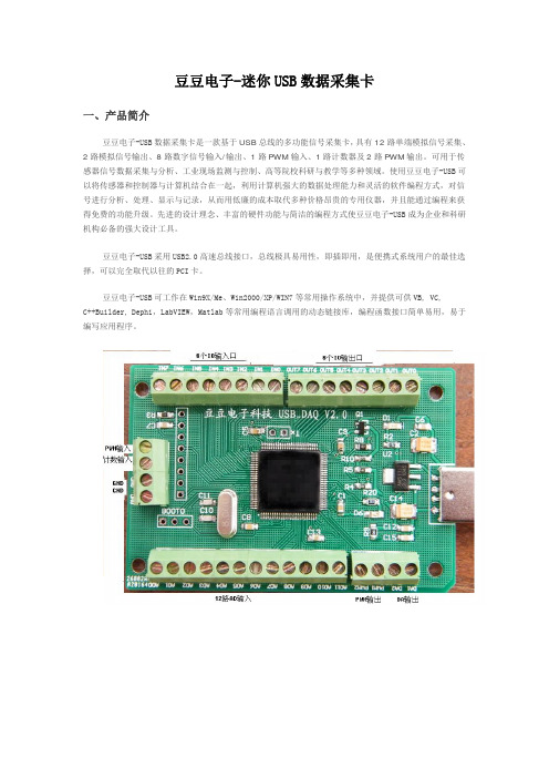
豆豆电子-迷你USB数据采集卡一、产品简介豆豆电子-USB数据采集卡是一款基于USB总线的多功能信号采集卡,具有12路单端模拟信号采集、2路模拟信号输出、8路数字信号输入/输出、1路PWM输入、1路计数器及2路PWM输出。
可用于传感器信号数据采集与分析、工业现场监测与控制、高等院校科研与教学等多种领域。
使用豆豆电子-USB可以将传感器和控制器与计算机结合在一起,利用计算机强大的数据处理能力和灵活的软件编程方式,对信号进行分析、处理、显示与记录,从而用低廉的成本取代多种价格昂贵的专用仪器,并且能通过编程来获得免费的功能升级。
先进的设计理念、丰富的硬件功能与简洁的编程方式使豆豆电子-USB成为企业和科研机构必备的强大设计工具。
豆豆电子-USB采用USB2.0高速总线接口,总线极具易用性,即插即用,是便携式系统用户的最佳选择,可以完全取代以往的PCI卡。
豆豆电子-USB可工作在Win9X/Me、Win2000/XP/WIN7等常用操作系统中,并提供可供VB, VC,C++Builder, Dephi,LabVIEW,Matlab等常用编程语言调用的动态链接库,编程函数接口简单易用,易于编写应用程序。
单位:mm二、性能指标2.1、USB总线性能●USB2.0高速总线传输●使用方便,能够实现自动配置,支持设备的热插拔即插即用2.2、模拟信号输入●模拟输入通道: 12路单端●输入端口耐压: 0—3.3V●输入信号量程: 0—3.3V●模拟输入阻抗: 10M●分辨率: 12Bit(4096)●最大总误差: < 0.2%●采样时钟: 100sps-100Ksps内部时钟(多通道50K)2.3、模拟信号输出●模拟输出通道: 2路单端(同步)●模拟输出范围: 0-3.3V●模拟输出电流: 1毫安●分辨率: 12Bit(4096)●非线性误差: ±2LSB●扫描时钟: 1sps-1000Ksps内部时钟2.4、数字信号输入/输出●输入/输出通道: 8路●输入/输出模式: 全输入/全输出●输入电平: 兼容TTL或CMOS●输出电平: CMOS2.5、PWM测量输入●个数: 1●输入电压: 0-3.3V●输入频率: 1—1MHz●输入占空比: 1%--99%●频率及占空比测量误差:1%2.6、计数器●计数器个数: 1●输入电平: TTL或CMOS●计数位: 32位(最大65535*65535)2.7、PWM输出●PWM输出通道: 2●PWM输出电平: CMOS●输入占空比:1%--99%●输出频率:1—1MHz2.8、工作温度●0℃ - 70℃三、应用领域便携式仪表和测试设备传感器信号采集与分析工业控制四、软件支持提供Windows95/98/NT/2000/XP/WINDOWS 7(32bit)下的驱动程序,提供通用DLL文件,并提供在LabVIEW和LabWindows图像化语言编写的应用软件范例程序。
YAV 1P NET-NB-IoT物联网通信转接器技术手册说明书
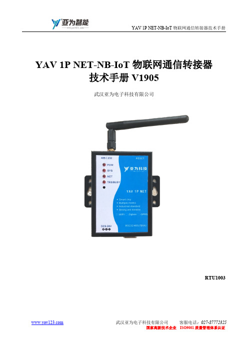
YAV 1P NET-NB-IoT物联网通信转接器技术手册V1905武汉亚为电子科技有限公司RTU1003序号版本号编写人编写日期支持对象应用时间特别说明1 1.0 郑先科2017.01 YAV 1P NET 采集卡2017.012 2.0 李雪2017.08 YAV 1P NET 采集卡2017.083 3.0 陈默2019.01 YAV 1P NET 采集卡2019.050. 产品概述 (1)1. 技术指标 (2)⏹ 供电 (2)⏹ 温度条件 (3)2. 硬件特点 (4)物联网模块特点 (4)原理框图 (6)机械规格 (7)3. 通信协议 (9)WSN无线或网络通信YAV IOT协议 (9)4. 应用实例 (14)无线连接方式 (14)发现硬件及配置 (14)软件功能 (15)5. 注意事项及故障排除 (16)注意事项 (16)⏹ 存储说明 (16)⏹ 出货清单 (16)⏹ 质保及售后 (16)⏹ 特别说明 (16)故障排除 (16)⏹ 无法正常连接至上位机 (16)⏹ 采集速度不够 (17)⏹ 软件出现错误 (17)6. 性能测试 (18)安全规范 (18)耐电压范围测试 (18)环境适应性测试 (19)7. 文档权利及免责声明 (21)8. 联系方式及公司简介 (22)9. 智能体验 (23)0. 产品概述7-24V直流电源供电,高速实现串口信号转NB-IoT的功能,包括不少于5种传输模式:透传、触发、询问、高速传输,支持Modbus RTU、YAV IOT等多种通信协议转NB-IoT,适应于不同使用场合,有配套的电脑软件,可在Windows XP、WIN7(32/64位)、WIN8(32/64位)、WIN10等操作系统下稳定运行,操作简单直观。
广泛应用于工业、电力、环保、农业等领域。
采集卡上预留多种通信接口,只可用其中一种,以实际选购确定的某一种为准。
11. 技术指标功能指标⏹供电●电源电压:DC7-24V●电源电流:>1A●额定功率:0.3W2⏹温度条件●工作温度范围:-30~70℃●存储温度范围:-40~80℃32. 硬件特点●供电保护:DC7~24V宽电压供电,防反接、防过流、低功耗、耐高温,采取多级滤波措施,抗干扰。
USB采集卡说明书
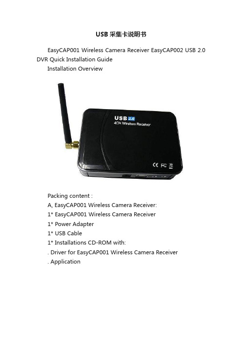
USB采集卡说明书EasyCAP001 Wireless Camera Receiver EasyCAP002 USB 2.0 DVR Quick Installation GuideInstallation OverviewPacking content :A, EasyCAP001 Wireless Camera Receiver:1* EasyCAP001 Wireless Camera Receiver1* Power Adapter1* USB Cable1* Installations CD-ROM with:. Driver for EasyCAP001 Wireless Camera Receiver. ApplicationB, EasyCAP002 USB 2.0 DVR1* EasyCAP002 USB 2.0 DVR1* Installations CD-ROM with:. Driver for EasyCAP002 USB 2.0 DVR. Application Connecting the EasyCAP001 Wireless Camera Receiver when you use it by TV, Monitor, or LCD Monitor: You must connect the Power Adapter to Wireless Camera Receiver when you use it by TV, Monitor, or LCD Monitor.(But no need this when you connect it to computer). And you can use Remote Controller to set any function (You can find the instruction for using remote controller in the bottom of this guide).Driver-Installationote: “If you have any anti-virus software enabled, please disable it during the installation of the software.”When you firstconnect the EasyCAP001 Wireless Camera Receiver ( or EasyCAP002 USB 2.0 DVR) to yourcomputer a Hardware Assistant will appear, the “USB 2.0 Video Capture Controller” will be recogni zed.Insert the “Installations CD-ROM” into your CD drive.Select the option “Install Driver” and click “Next”.If prompted “Can Windows connect to Windows Update to search for software?” select “No, not this time” and select “Next”. Select the option “I nstall the software automatically”and click “Next”.A window may appear about the “STK1160 ATV BDA” notpassing the windows logo testing, select “Continue Anyway”.When “Completing the Found New Hardware wizard” windowappears click the “Finish” button to complete the driverinstallation.ote: ”If any further components are found please repeat the NNabove process until you receive the message “Found newhardware: Your hardware is installed and configured use”You will now need to check that The drivers are installed correctly.Right Click on My Computer and Left Click on Properties. Click on Hardware tab and then Device Manager.In the “Device Manager”, click on the “+symbol”on the“Sound Video and Game controllers”section. If thedriver is installed correctly you should see the “STK1160ATV BDA”. If it has a Yellow mark next to it then thismeans that the driver is not installed correctly. You willneed to remove the driver and disconnect theEasyCAP001 Wireless Camera Receiver ( orEasyCAP002 USB 2.0 DVR) from the computer and re-connect is to install the driver again.Software InstallationTo start the Application Installation, click Start / Run then type your CD-ROM and click “Install.Select your language for the installation and Click “Next” or / and“Install”.Click “finish” to complete setup, restart your computer if needed.Run MultiViewer which you just installed.Introduction MultiViewerMultiViewerMultiViewer is a 4-channel wireless video surveillance software for Windows. It has advanced video viewer separate algorithm, various alert functions including schedule timer sanp, channel control, and sound. It can handle up to 4-channels video input, captures images up to 30 frames per second from USB video capture device. It uses be installed in Windows's video encoder and audio encoder , high quality video and audio effect , record file format A VI. The files can played with Windows Media Player or Real Player etc. JPEG image snapshots can be made from video images. Other features include secure Manual Control Channel,audio listening etc.Features1.Send e-mails attachment with image.2.Save image on Hard Disk.3.Sound alarm.4.Video signal filter, for filtrate Active and Invalid chunnel.5.Signal lost alarm.6.Motion Detection.7.Adjustable sensitivity.8.Automatically lock, while not any operate.9.Schedule Monitoring sessions, for timer snap.10.Record video/audio(with usb2.0 audio interface),snap shot.11.Automatic Space Managment. Stop recorder or capture still automatically on disk full.12.Support 4 Channel Video input on one computer.13.Support On Screen Display. Displys date and time ,or channel description on video.14.Supports manual open/close Invalid channel, or add/delete channel description.15.Supports login and logout, by UserName and Password.16.Supports running background stealthy.System requirementsWindows 2000/XP or better1.7GHz CPU or better128M memory or betterMicrosoft DirectX 9.0CUSB2.0 InterfaceAudio Card / True Color VGA CardMULTIVIEWER APPLICATION USER GUIDEThe MultiViewer Application can be started by clicking on the MultiViewer icon or by using the Start menu. The Following window should appear:A. Viewer Mode - Select viewer mode, such as Four Viewer, Big & Four Viewer and Single Viewer.B. Viewer Window - Show video image.C. Audio Play - For audio remote listening, with USB2.0 Audio interface .D. Login&Logout - Login and Logout the MultiViewer, by Username and Password.E. Camera/Channel Selection - Click the buttion,select Camera/Channel.F. Auto turning foucs - Click the "ON" buttion to enable, and click the "OFF" buttion to disable.G. Channel Settings -Such as channel description, channel active/inactive etc.H. System Settings - Adjust video recorder settings, such as Save A VI File Path etc.I. Record -Start and end video recordJ. Property - Advanced Settings video picture settings and fine tuning.K. Show Stamp -Show MultiViewer's system information,such as channel description, etc.L. Timer Snap - Captures and saves a bitmap picture after Schedule end.Timer adjustable by clicking on have file options button. Ref. N)M. Snap Shot -Capture and saves an instant bitmap picture.N. Save File - Settings Schedule for timer snap, displays and allows capture of destination path and filename of bitmap capture file.O. Security&Surveillance - Include E-Mail Sever Setup, Motion Detction Setup, Signal Lost Setup, Sensitivity Setup, and Auto Logout Setup.Schedule Timer Capture Still1. Settings Timer Snap Schedule and Save Image File Path [*](ref. N in Figure1)2. Click on Timer snap Button (ref. L in Figure1)(Note. Default files will be saved under MultiViewer installing folder. Such as: C:\Program Files\MultiViewer\Picture ) [*] Default Settings as follows Figure :Video Capturing1. Click on the Recorder button to begin recording. (ref. I in Figure1).2. To stop recording click on the same button.3. Output file path [*] can be changed by clicking the System button ( ref. H in Figure1)[*] Default files will be saved under MultiViewer installing folder. Such as: C:\Program Files\MultiViewer\Video Channul SettingsYou can select the video channel active or inactive by simply selecting CH1 of the CH4 options. You can add chunnel description in the viewer screen. The default setting as follows Figure :If you seletc the "Manual" button, MultiViewer will immediately stop control video channel, and main panel as showIf you click the "Reset" button, MultiViewer will start signal fiter for search the video channel again, and main panel as showNote:You can click the "SEARCH" button, to stop search the video channel.Security&Surveillance SettingsYou can select the motion detection, signal loset alarm, auto logout active or inactive by simply selecting the options. You can adjust the sensibility. The setting as follows Figure :If you select the "Open alarm sound" button, MultiViewer open alarm while condition active, and main panel as showNote:[1]You an click the "ALARM" button, to stop play sound.[2]Default still will be saved under MultiViewer installingfolder. Such as C\Program Files\MultiViewer\Picture\Motion. Advanced SettingsThe advanced settings window allows the user to adjust image characteristics by clicking on the Camera Controls tab. Camera Controls T abUse the picture property window shown below to adjust picture quality. By sliding the Control Adjust Bar the effect can be seen immediately on the viewer window. These setting can be saved by clicking the save button or cancelled by restoring thedefault settings.Check Box control features include:- NTSC, PAL, Vertical Flip, Mirror Flip and Backlight Composition.Instruction of remote controller (EasyCAP001)Note: The remote control only work for control the hardware device, not for the application of this device. Please do not use the channel auto-view function with both application and remote control at same time.When you connect the device to computer, or with power supply to connect to other show monitor with AV-IN, the greenlight will on, click the “power” button on the remote controller, the green light will be off, it means the device will be controlled by remote, and in this situations, the application wont control the channel selection if you connect the device to computer. (So, we do not suggest you use remote controller when you connect this device to computer).Key functionsPower on/off: only works for when using power adaptor.CH1~CH4: to select the 1~4 channel on.Auto: stop/start channel auto-view, automatically select CH1-CH2-CH3-CH4, then CH1...The default speed is 1 time/second (you can also change the speed with using "CH1~CH4", for example: when you click "CH1" then click "Auto" the speed will be 1 time/second, CH2 for 2 time/second and so on...Set: If you do not want to view any channel(s) of your camera, because some reason or you do not have 4 cameras, you can choose to skip the channel(s) when you using channel auto-view function. Use "SET" key and “CH1~CH4” keys you can set the LED light on and off for channel1~channel4 to make the relevant channel(s) be skipped. (light on means the channel working light off means the channel is skipped)。
接口函数库(二次开发库)使用说明书

接口函数库(二次开发库)使用说明书说明书版本:V2.06更新日期:2020.01.01目录第一部分概述 (1)第二部分兼容ZLG函数库及数据结构 (2)2.1 类型定义 (2)2.1.1 Device Type (2)2.1.2 VCI_BOARD_INFO (2)2.1.3 VCI_CAN_OBJ (3)2.1.4 VCI_INIT_CONFIG (5)2.2 函数描述 (8)2.2.1 VCI_OpenDevice (8)2.2.2 VCI_CloseDevice (9)2.2.3 VCI_InitCan (9)2.2.4 VCI_ReadBoardInfo (12)2.2.5 VCI_GetReceiveNum (13)2.2.6 VCI_ClearBuffer (14)2.2.7 VCI_StartCAN (15)2.2.8 VCI_ResetCAN (16)2.2.9 VCI_Transmit (17)2.2.10 VCI_Receive (18)第三部分其他函数及数据结构描述 (21)3.1 类型定义 (21)3.1.1 VCI_BOARD_INFO1............................................................ 错误!未定义书签。
3.2 函数描述 (21)3.2.1 VCI_UsbDeviceReset (21)3.2.2 VCI_FindUsbDevice (22)第四部分接口库函数使用流程 (24)I第一部分概述用户如果只是利用USB-CAN总线接口适配器进行CAN总线调试,可以直接利用随机提供的USB-CAN Tool工具软件,进行收发数据的测试。
如果用户打算编写自己产品的软件程序。
请认真阅读以下说明,并参考我们提供的:① C++Builder ②C# ③VC ④VB ⑤ ⑥Delphi ⑦LabVIEW ⑧LabWindows/CVI ⑨Matlab等示例代码。
简易 YAV WSN WIFI 无线采集卡二次开发说明(IOT通信协议)201708

通信协议WSN无线通信此处为简版,详见《YAV WSN 无线采集卡二次开发指南(IOT通信协议)》本说明亚为所有无线采集卡通用,包括无线 2AD、8AD、16AD、8IO的WiFi、zigbee、蓝牙和433M无线等无线接口的采集卡。
本协议从2017年6月1日起售出的产品生效。
注意事项:采集卡不可拆卸,否则不予退换或质保。
采集卡出厂默认为UDP热点,账号为YAV,密码为yav123456,IP为192.168.4.1。
用户可不经任何配置,直接在电脑或者手机上接入YAV热点(手机请注意关闭自动切换WIFI功能),使用UDP网络助手或亚为提供的软件快速接收数据,也可以配置参数,可具体数据格式参见后文。
使用流程串口配置工具,新采集卡电脑AP\IP必须配置一次没有串口的用户,也可以直接使用安卓手机APP配置硬件配置(以串口配置为例)串口设置:115200,N,8,1,以下步骤,必须在串口连接正常的情况下,通过COM口发送数据至WiFi采集卡。
可以用任意串口助手或者亚为配置助手配置。
备注:由于在出厂之前必须经过设备检测合格才能出厂,所以配置之前出现直接开始连接WiFi属于正常情况,请用户重新配置即可。
用户配置完成后,请尽量减少恢复出厂设置和重新配置的行为,以免对WiFi 采集采集卡造成损伤。
配置时,偶尔反馈乱码,这是正常现象。
注意:串口配置模式下,命令格式是是@XXX:XXX,命令必需在配置过程中才有效并被执行,英文符号,注意区分大小写。
网络通信模式下,命令是XXXX=XX_XX采集卡网络初始化配置串口设置:默认115200 N 8 1,以下命令不分先后,皆可独立配置。
也可在采集卡做YAV热点的情况下,通过UDP发送命令配置,具体可参考“亚为配置助手”APP。
1、进入配置模式采集卡加电,5s内串口发送@SET返回:进入配置模式……如果用亚为的软件配置,只需重新上电即可,无需人工发送指令。
2、配置AP(只对WiFi有效)串口发送@AP:D298,yavii123返回:本字符串,其他命令与此相同。
二次开发接口说明V3.0

⼆次开发接⼝说明V3.01.概述精伦电⼦开发的⼆代⾝份证读卡系列机具适⽤于相关⾏业的联机型应⽤。
产品提供了完善的⼆次软件开发接⼝(API)。
本⼿册对开发接⼝的⽂件组成、函数定义格式、调⽤⽅法及返回值等进⾏详细的说明。
本通⽤开发包⽀持的设备型号如下:1、iDR200(串⼝和USB⼝)。
2、iDR320(必须进⼊“同步应⽤”模式)。
3、iDR400-1(必须进⼊“同步”模式)。
4、iDR210(USB-HID免驱动接⼝)。
5、iDR210(串⼝)。
注意:完全兼容原2.0版本开发接⼝,⽀持USB-HID接⼝和串⼝的iDR210。
1、如果使⽤原开发包采⽤动态调⽤dll⽅式,只需直接替换原dll即可。
2、如果使⽤原开发包采⽤的静态调⽤⽅式,则在不改变代码的情况下,对原程序重新编译链接即可。
2.系统要求使⽤本API的PC机,必须满⾜下列条件:●Windows 98、Windows 2000 Pro、Windows 2000 Server、Windows XP。
●⾄少32兆内存(32M RAM or Larger)。
●⾄少10兆空闲硬盘空间(10M Free Hard Disk Space or Larger)。
●⾄少⼀个空闲普通串⼝或USB⼝(视⽤户需求⽽定)。
3.接⼝⽂件说明接⼝⽂件包括:Dewlt.dll 相关动态联接库sdtapi.dll 相关动态联接库JpgDll.dll 相关动态联接库SavePhoto.dll 相关动态联接库sdtapi.h 相关动态联接库头⽂件适⽤开发语⾔:Visual C++ 5.0 及以后版本C++ Builder 5.0 及以后版本Visual Basic 5.0 及以后版本Delphi 3.0 及以后版本PowerBuilder 5.0 及以后版本4.接⼝函数说明4.1.端⼝函数4.1.1.端⼝初始化函数原型:int InitComm (int iPort)说明:本函数⽤于打开串⼝或USB并检测读卡设备是否就绪。
USB视频采集卡使用说明书

其余三个 口均不接
2.测试线和采集卡的连接方法 测试线莲花头一端接在 USB 视频采集卡的黄色端子,另一端有 2 头
出线,分别是信号线(接 VTO)和地线,注意:测试线有 2 个出头,连 接时需要用万用表测一下导通;其中和莲花头外壳导通的接 GND,和 莲花头中心导通的接 VTO。
产品特性
◎ 支持 USB2.0,无需打开机箱,支持热插拔,支持笔记本电脑 ◎ 自行调整画面大小、最高分辨率可达 720×576,24 位真彩色 ◎ 最新技术 USB AUDIO、立体声输入输出 ◎ 图像亮度、对比度、饱和度、色度可自定义 ◎ 可捕捉高品质动态及静态画面,采集画面顺畅不间断 ◎ 输入接口有 AV 及 S 端子,可在台式机或手提电脑上观看录像、VCD、 DVD、摄像机等设备输出的视频影象 ◎ 支持 MPEG1/2 等多种实时压缩格式,方便制作 VCD/SVCD/DVD ◎ 兼容 WINDOW XP/Win7,兼容 Direct8.1、9.0
即在属性对话框中的 Image 标签下,选择“PAL/M”和“组合”选项, 确定后,即可在显示区看到摄像头图像了;如果此时还没有图像显示, 请调到第二步检查电气连接是否正确。
2.《USB 视频采集卡-Win7 版》
第一步 打开文件包,点击 Setup,进行软件安装。一直点击下 一步进行安装。
安装完成后,在桌面上回生成如下图所示的图标
插好 USB 视频采集卡,打开软件。如果 USB 视频采集卡没有插好, 或者 USB 口驱动电流不足,或者 USB 口接触松动,打开软件的时候会 出现以下错误:
更换 USB 口或者重新拔插几次,就可以打开软件了。如果重复几 次不可以打开软件,那么重新启动系统或者调到第三步重新安装软件 和驱动。
National Instruments USB-6000 OEM设备参考指南说明书
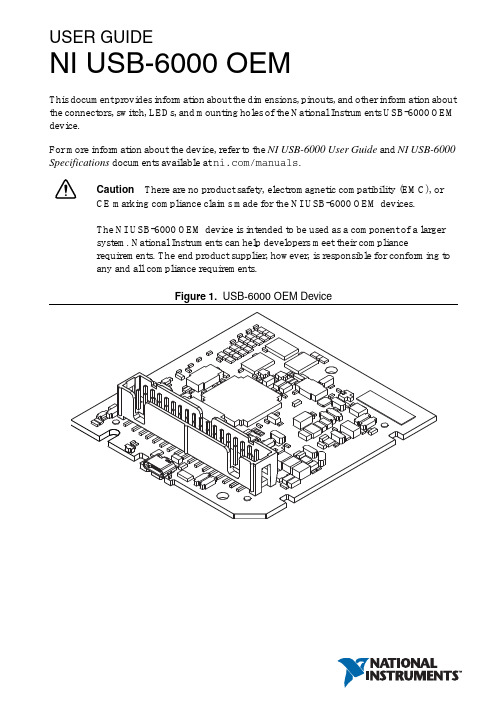
USER GUIDENI USB-6000 OEMThis document provides information about the dimensions, pinouts, and other information about the connectors, switch, LEDs, and mounting holes of the National Instruments USB-6000 OEM device.For more information about the device, refer to the NI USB-6000 User Guide and NI USB-6000 Specifications documents available at /manuals.Caution There are no product safety, electromagnetic compatibility (EMC), orCE marking compliance claims made for the NI USB-6000 OEM devices.The NI USB-6000 OEM device is intended to be used as a component of a largersystem. National Instruments can help developers meet their compliancerequirements. The end product supplier, however, is responsible for conforming toany and all compliance requirements.Figure 1. USB-6000 OEM DeviceUSB-6000 OEM Device SpecificationsMost specifications of the USB-6000 OEM device are listed in the NI USB-6000 Specifications document on /manuals. The following sections contain exceptions to the main specifications.Physical Characteristics Weight...............................................................23 g (0.811 oz) Dimensions.......................................................693 mm × 658 mm × 117 mm(2.73 in. × 2.59 in. × 0.46 in.)Figure 2. USB-6000 OEM Device Dimensions in Inches (Millimeters)2||NI USB-6000 OEM User GuideI/O Connector PinoutsFigure3 shows the USB-6000 OEM device I/O connector pinouts.Figure 3. USB-6000 OEM Terminal AssignmentsSignal DescriptionsMost of the signals available on the I/O connector are described in the NI USB-6000 User Guide document available for download at /manuals. Table1 describes additional signals on the I/O connector of the OEM device.Table 1. Additional Signal DescriptionsSignal Name Reference Direction Description VBUS D GND Input USB PowerD+, D- D GND Input/Output USB Data LinesLED D GND Output Status LED DriverFor more information about USB signals, refer to the Universal Serial Bus Specification accessible at .NI USB-6000 OEM User Guide|© National Instruments|34| |NI USB-6000 OEM User GuideUsing the 34-Pin Connector with a Board Mount SocketThe USB-6000 OEM device can be mounted to a motherboard using the 34-pin connector, as shown in Figures 4 and 5.Figure 4. Mounting Using a 34-Pin ConnectorNoteRefer to the Device Components section for more information aboutmounting components.Figure 5. USB Device Installed on Motherboard1Board Mount Socket 234-Pin Connector3USB-6000 OEM Device4Mounting Screw 5Mounting StandoffConnecting to USBYou can use the USB connector on the USB-6000 OEM device to connect to the USB host. In this case, leave the D+ and D- signals (on the 34-pin connector) and VBUS unconnected.You can also use a USB connector on your motherboard to connect the USB-6000 OEM device to the USB host through the 34-pin connector. In this case, do not connect to the USB connector on the USB-6000 OEM device.Using the Status LED DriverThe LED signal indicates the device status as listed in the NI USB-6000 User Guide document on /manuals. An open collector output drives the LED signal. For applications that use the LED signal, connect an external pull-up resistor from the LED signal to an external voltage.To drive a status LED, refer to the circuit as shown in Figure6.Figure 6. To Drive a Status LEDTo use the LED signal to monitor the device state, refer to the circuit as shown in Figure7.Figure 7. To Monitor Device State Through the LED SignalNI USB-6000 OEM User Guide|© National Instruments|56| |NI USB-6000 OEM User GuideElectrical CharacteristicsTable 2 lists the LED electrical characteristics.Device ComponentsTable 3 lists the components used for interfacing and interacting with the USB-6000 OEM device.Table 2. LED Electrical CharacteristicsParameter Condition Typical MaximumOutput Low V oltageI OL = 8 mA —0.4 V I OL = 18 mA1.2 V —External Pull-up V oltage —— 5.25 V Maximum Sinking Current——18 mATable 3. NI USB-6000 OEM Device ComponentsComponent Reference Designator(s) on PCBManufacturerManufacturer Part NumberPartSpecificationsMicro USB connector J001Molex 105164-0001—Hi-Speed USB cable, A to Micro-B, 1m —NI 782909-01—Hi-Speed USB cable, A to Micro-B, 2m —NI 782909-02—34-pin connector J0023M N2534-6V0C-RB-WF —34-pin mating connector—3M 8534-4500PL (or equivalent)—Mounting StandoffUsing 34-pin board mount socket ———4.76 mm (3/16 in.) HEX female-to-female, 15 mm (0.59 in.) long Using ribbon cable———4.76 mm (3/16 in.) HEX female-to- female, 6.35 mm (1/4 in.) long Screw ———M3 × 0.5, 4-40 UNCWhere to Go for SupportThe National Instruments Web site is your complete resource for technical support. At / support you have access to everything from troubleshooting and application development self-help resources to email and phone assistance from NI Application Engineers.National Instruments corporate headquarters is located at 11500 North Mopac Expressway, Austin, Texas, 78759-3504. National Instruments also has offices located around the world to help address your support needs. For telephone support in the United States, create your service request at /support and follow the calling instructions or dial 512 795 8248. For telephone support outside the United States, visit the Worldwide Offices section of / niglobal to access the branch office Web sites, which provide up-to-date contact information, support phone numbers, email addresses, and current events.Refer to the NI Trademarks and Logo Guidelines at /trademarks for more information on National Instruments trademarks. Other product and company names mentioned herein are trademarks or trade names of their respective companies. For patents covering National Instruments products/technology, refer to the appropriate location: Help»Patents in your software, the patents.txt file on your media, or the National Instruments Patents Notice at /patents. You can find information about end-user license agreements (EULAs) and third-party legal notices in the readme file for your NI product. Refer to the Export Compliance Information at /legal/export-compliance for the National Instruments global trade compliance policy and how to obtain relevant HTS codes, ECCNs, and other import/export data.© 2013 National Instruments. All rights reserved.373896A-01Aug13。
USB采集卡使用说明简介
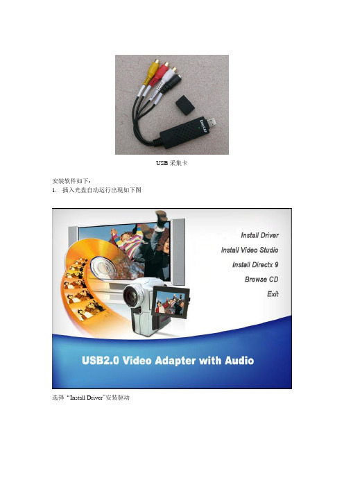
USB采集卡
安装软件如下:
1.插入光盘自动运行出现如下图
选择“Install Driver”安装驱动
点击”安装”,出现下列提示:
点击”仍然继续”
点击”完成”,出现提示:
OK,找到驱动后就可以了。
下面我们再来按装应用软件。
在自动运行的界面上点击第二个安装即“Install Video Studio”步骤如下:
点“下一步”
继续“下一步”
选择“接受”点“下一步”
输入序列号:(序列可以装光盘的袋子上找到或在光盘里面的里面。
然后点“下一步”
继续“下一步”
这里可以选择地区,一般默认即可。
点“下一步”
继续“下一步”会看到安装的进度:
点击“完成”并重启电脑。
重启后就打开桌面上的图标:
选择“会声会影编辑器”
出现注册提示:
点“以后注册即可”
出现这个界后面选择采单栏的“捕获”
再选择:
这时会自动改变场的顺序点确定。
出现些界面:
选择”选项”里的第二个(视频音频捕获属性设置)
在来源里面的输入来源,选择”视频组合”点确定就可以了。
(此步很重要)这时就可以看到以下画面了。
在这里可以设置保存的路径(录像和拍照的存放的位置)
点即可以录像
点即可以拍照
以上就是这样了。
希望朋友们用的顺心!。
YAV USB MAX PRO 多功能采集卡技术手册USB65721

YAV MAX PRO USB采集卡通信技术手册V1801武汉亚为电子科技有限公司USB65721关于本手册为亚为推出的YA V MAX数据采集卡的用户手册,主要内容包括功能概述、应用实例、性能测试、注意事项及故障排除等。
说明序号版本号编写人编写日期支持对象应用时间特别说明1 1.0郑先科2014.05YA V MAX PRO采集卡2 2.0郑先科2016.01YA V MAX PRO采集卡3 3.0郑先科2017.01YA V MAX PRO采集卡2017.01适用于RS232\485\WiFi\GPRS ZIGBEE\蓝牙\433M无线4 4.0李雪2017.08YA V MAX PRO采集卡2017.08目录0.快速上手 (1)产品包装内容 (1)应用软件 (1)接口定义 (1)⏹端子排列 (1)⏹端子描述 (2)通信 (3)1.产品概述 (3)技术指标 (3)⏹模拟信号输入 (4)⏹数字信号输入 (5)⏹数字信号输出 (5)⏹模拟信号输出 (6)⏹PWM输入 (6)⏹PWM输出 (6)⏹通信总线 (6)⏹温度参数 (6)硬件特点 (7)原理框图 (7)2.采集卡信号接线 (9)AI模拟量接线 (9)DI数字量接线 (9)DO数字量接线 (10)3.模拟量输入功能 (11)模拟量输入 (11)输入采样原理 (11)输入接线 (11)采样值计算 (12)⏹无符号整型 (13)⏹ADC数据类型 (13)⏹模拟量值 (13)4.模拟量输出功能 (13)输出原理 (13)5.数字量输入功能 (14)数字输入原理 (14)DI高低电平/无源触点输入 (15)计数功能输入 (15)测频功能输入 (15)PWM功能输入 (15)编码器输入 (16)AO输出匹配输入 (16)输入接线方式 (16)6.数字量输出功能 (17)输出原理 (17)DO高低电平输出 (18)输出接线方式 (18)PWM输出 (19)7.通信协议 (19)USB通信 (19)加载流程 (19)8.应用实例 (24)采集卡连接 (24)发现硬件 (25)软件功能 (25)软件应用 (26)⏹LabVIEW (26)⏹其它 (26)9.注意事项及故障排除 (27)注意事项 (27)⏹存储说明 (27)⏹出货清单 (27)⏹质保及售后 (27)⏹特别说明 (27)故障排除 (27)⏹无法正常连接至上位机 (27)⏹VI文件打不开 (28)⏹数值不正常 (28)⏹多卡数据相同 (28)⏹采集速度不够 (29)⏹软件出现错误 (29)10.性能测试 (29)安全规范 (29)耐电压范围测试 (30)环境适应性测试 (30)信号性能测试 (31)11.文档权利及免责声明 (33)12.联系方式.......................................................................................................................错误!未定义书签。
亚为USB采集卡通用采集平台 使用说明
亚为USB采集卡通用采集平台(UMS2016)操作说明武汉亚为电子科技有限公司版权所有不得私自转载一、平台简介(一)功能说明1、本程序自适应亚为所有USB接口的硬件,通道数量能完全自适应。
2、具备长时间低速模拟量AI采集、短时间高速AI采集,波形显示、分析、回放等功能。
3、最下方的DI、DO、计频、计数等,是部分硬件具备的功能,具体视硬件接口而定。
(二)使用方法1、安装与学习LabVIEW,见“LabVIEW入门教程”2、运行左上角向右的箭头3、根据提示检查硬件4、按下Ctrl+E可以查看后台程序,修改后台参数5、制作exe文件,见“LabVIEW如何制作EXE和SETUP文件”(三)注意事项1、本程序仅供参考,非经亚为授权,不得用于商业用途2、亚为不对用户修改过的程序负责3、程序更新,恕不另行通知4、必须整个压缩包解压缩运行,否则dll文件无法调用5、硬件首次插入电脑,需要耐心等到30s左右6、软件如有bug,欢迎批评指正二、系统功能主界面表盘显示柱状图显示参数配置帮助三、功能详解1、该平台能自适应硬件。
连接上硬件后,会自动适应通道数和量程。
2、低速采集:用于长时间信号采集,采样率不高,一般一秒采集次数为5次以下,在内存允许的情况下,该模式可以无限时长的工作下去。
3、高速采集:具体速度视采样率而定,由于数据量大,平台只记录一小段时间的数据。
4、表盘显示:用于仿真仪表盘显示,形象逼真。
5、柱状图显示:用于仿真液位图,形象逼真。
6、配置参数:配置通道、校准参数、上下门限和报警设置等参数。
系统能自动将用户配置的参数保存于data文件夹下的ini文件内。
该文件不可更改路径和名称。
7、帮助:提示信息8、量程自动显示:自动识别采集卡的量程9、采样率设置采样率设置主要适用于高速采集界面,低速采集因已有较大时间间隔,因此影响很小。
直接改变采集卡内部采样率参数,因此改变采样率后,高速采集显示界面数据显示速率也会有明细变化。
二次开发接口文档
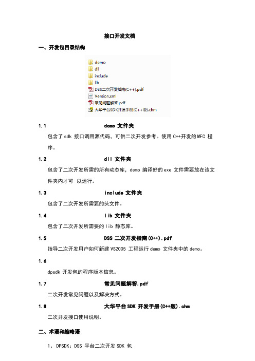
接口开发文档一、开发包目录结构1.1demo 文件夹包含了sdk 接口调用源代码,可供二次开发参考。
使用C++开发的MFC 程序。
1.2dll 文件夹包含了二次开发所需的所有动态库,demo 编译好的exe 文件需要放在该文件夹内才可以运行。
1.3include 文件夹包含了二次开发所需要的头文件。
1.4lib 文件夹包含了二次开发所需要的lib 静态库。
1.5DSS 二次开发指南(C++).pdf指导二次开发用户如何新建VS2005 工程运行demo 文件夹中的demo。
1.6dpsdk 开发包的程序版本信息。
1.7常见问题解答.pdf二次开发常见问题以及解决方式。
1.8大华平台SDK 开发手册(C++版).chm二次开发接口使用说明。
二、术语和缩略语1、DPSDK:DSS 平台二次开发SDK 包2、CMS:中心管理服务3、DMS:设备管理模块4、demo:程序示例(功能类似DSS 平台客户端)5、web 管理员端:在浏览器中输入DSS 平台的ip 即可打开管理员端6、CameraID:通道id,形如:$1$0$07、DeviceID:设备id三、Demo 操作方法运行demo把“demo/bin/”目录下面的3 个文件,如下图所示拷贝到“dll”文件夹下面,运行。
登陆平台图 1 登陆界面登陆界面如图 1 所示,其中: IP:DSS 平台ip 地址;端口:9000;用户名:web 管理员端配置的用户;密码:web管理员端配置的用户对应的密码。
点击“登录”按钮,登陆平台。
登陆成功的界面如图2 所示:1235图2 主界面上图选中的 5个模块分别是:1、组织树;2、实时视频;3、本地录像;4、云台操作;5、执行结果。
主界面功能介绍、组织树操作步骤:点击“加载所有组织结构”按钮加载组织结构是其他操作的前提,是为了获取 DSS平台上所有的设备信息。
、实时视频模块操作步骤:1)确保已经成功加载组织结构。
2)输入CamID(通道ID)。
- 1、下载文档前请自行甄别文档内容的完整性,平台不提供额外的编辑、内容补充、找答案等附加服务。
- 2、"仅部分预览"的文档,不可在线预览部分如存在完整性等问题,可反馈申请退款(可完整预览的文档不适用该条件!)。
- 3、如文档侵犯您的权益,请联系客服反馈,我们会尽快为您处理(人工客服工作时间:9:00-18:30)。
int GetYavData(unsigned short TaskID,int *DAQDataBuffer, unsigned int DataSize, int *YavParam, int *CNTBuffer, unsigned int *IOBuffer) 返回:设备临时 ID,返回数值大于 254,表示硬件异常,其中 255 表示通信超时,256 调用函数错误, 硬件通信失败。临时 ID 用于多卡同时连接于一个电脑。 为了开发方便,此函数可在不调用 FindDevice 、OpenYavDevice 函数的情况下,单独使用,第一次 调用报错,第二次之后便可实现连续采集。 例如 int DAQDataBuffer[64]={0},YavParam[1]={0},CNTBuffer[2]={0},IOBuffer[2]={0} GetYavData(0,DAQDataBuffer,64,YavParam,CNTBuffer,IOBuffer) 其中: TaskID:USB 设备任务编号,0; DAQDataBuffer:缓存数据数组,初始化长度必须大于 DataSize;LabVIEW 中数据类型为无符号 32 位 整 形 , 其 他 平 台 均 为 unsigned int 。 数 据 根 据 通 道 数 全 通 道 交 叉 排 列 , 【 X00 X01…X0N……X10 X11…X1N……XMN】,其中 M 是通道数,M 由采集卡型号决定,N 单次是采样长度,必须为 64 的整数 倍。例如两路采集卡,是 0 1 0 1……,8 路是 0 1 2 3 4 5 6 7 0 1 2 3 4 5 6 7……,16 路是 0 1 2~15 0 1 2……, 循环排列。 数据解算:单极性采集卡,例如 0-10V 量程,AI 精度 12 位,为无符号数,转换为十进制,除以 4095, 再乘以量程。例如 10V 量程,再乘以 10(实际电阻会有偏差,9.83 会比较精确,具体可用其他第三方设备 做校准)会得到通道数据,即真值 X*9.83/4095。正负量程的双极性采集卡,例如 AI 精度 16(或 24 位), 为有符号数,转换为十进制,除以 2^(16-1)-1,再乘以量程。例如±10V 量程,再乘以 20。 DataSize:单次采样长度,必须为 32 的整数倍,例如 32 256 512 1024 2048,最大为 81920,是几个通 道加起来的数据长度,例如 1024 表示每个通道 512,不可用其他数值,越小越快,越大每次采集的越多更 新越慢。为了显示通畅,一般设置为采样率的四分之一到一半,例如 1k 采样率,设置 512 为宜。 YavParam:采集卡参数数组,初始化长度必须大于 1。依次为报警、采样率、通道数、量程。具体参 数范围及含义见“配置命令一览表” 。
3 武汉亚为电子科技有限公司
YAV USB 采集卡二次开发即 DLL 使用手册
CNTBuffer:数字量读数数组,初始化长度必须大于 2。分别对应通道 1 通道 2 计数/测频。 IOBuffer:IO 量状态数组,初始化长度必须大于 2。分别对应 DI、DO 状态。0 代表 DI 都为低电平,1 代表 DI0 高,DI1 低,3 代表都为高电平。 务必对每一个参数提供正确初始化值,尤其是数组必须注意长度,否则 VB\VC 等平台调用会 出现错误或者崩溃。 配置设备 SetYavParam
4 武汉亚为电子科技有限公司
YAV USB 采集卡二次开发即 DLL 使用手册
DAQDataBuffer:缓存数据数组,初始化为 36 个长度的数组, 0-31 为通道 AI,32-35 分别为 DI0\DI1 的测频计数、DIDO。LabVIEW 中数据类型为无符号 32 位整形,其他平台均为 unsigned int。数据根据通道 数全通道交叉排列,【X00 X01…X0N……X10 X11…X1N……XMN】,其中 M 是通道数,M 由采集卡型 号决定,N 单次是采样长度。例如两路采集卡,是 0 1 0 1……,8 路是 0 1 2 3 4 5 6 7 0 1 2 3 4 5 6 7……,16 路是 0 1 2~15 0 1 2……,循环排列。 单次设置数据 SetYavOnce int SetYavOnce(unsigned short TaskID,unsigned char *YavParam) 返回:1 代表成功,非 1 失败 例如 int YavParam[16]={0,1,2,3,4,5,6,6,7} GetYavData(0,YavParam) 其中: 该函数为不用调用 FindDevice\ OpenYavDevice\ SetYavParam 等函数,简易高速单次读取所有通道参数 的函数,能自动打开设备,读取后关闭设备的方法,简单易用,对于采样率要求不高的开发者非常实用。 YavParam:地址+命令+数据,联合单次下发,最多可一次性写入 16 个数据。 关闭设备 CloseYavDevice Int CloseYavDevice(unsigned short TaskID)
返回:1 代表成功,非 1 失败 例如 CloseYavDevice(0) 注意: 本 DLL 适用于任何可以调用 dll 的开发平台,经过测试,目前能支持几乎所有平台所有版本的数据采 集,不存在 dll 无法调用或者错误的情况。如果您在开发的过程中发现错误,多半是 dll 加载不正确,或者 输入的参数有误。64 位平台注意加载 ADIO64.dll,编译时注意选择 x86 还是 x64。 请注意数据类型,以及数组缓冲区大小。如果缓冲区太小,就会出现内存错误。所以申请数组,可以 尽量大一些空间。
int OpenYavDevice (unsigned short TaskID)
2 武汉亚为电子科技有限公司
YAV USB 采集卡二次开发即 DLL 使用手册
返回:设备临时 ID,返回数值大于 254,表示硬件异常,一个卡就是 0,两个卡就分别为 0,1,255 失 败。 TaskID:USB 设备编号,单设备为 0(默认),多个设备为 0 1 2……。 例如 OpenYavDevice (0) 读取数据 GetYavData
YAV USB 接口的采集卡,无需安装驱动,可利用 ADIO86.dll 与其他开发平台产生数据交互,dll 基于 VS2010 开发。部分操作系统加载 dll 时出错,需 msvcr100d.dll、msvcr120d.dll 配合使用,直接放 ADIO86.dll 同文件夹下即可,如果是 64 位开发平台(注意:64 位操作系统如果用的是 32 位开发平台,依然需要使用 ADIO86 版本),可 ADIO64.dll 改名为 ADIO86.dll ,替换并重启软件。该 dll 可用于通用开发平台,例如 VC++、VB、C#、Delphi 等。
—— FF(CH0 测频) CC(CH0 开始计数) N(0-F)参考 FA —
——
——
6 7 6 系 7 数 8 校 9 准 10 11 零 12 漂 13 校 14 准 15 16
AI 连续采集 特殊采集 读取校准系数 CH0-6 校准系数 CH7-13 校准系数 CH13-19 校准系数 CH20-27 校准系数 读取漂移 CH0-6 校准系数 CH7-13 校准系数 CH13-19 校准系数 CH20-27 校准系数 数字量 DO 控制※
5 武汉亚为电子科技有限公司
YAV USB 采集卡二次开发即 DLL 使用手册
表 1 配置命令一览表
序 功 号 1 2 停止采集 单次采集 能
16 进制
命令 CMD 0xA0 0xA1 D0 —— —— D1 —— —— 触发电平 触发电平(高位) 参数数组 备注 D2 —— —— 长度 (高位) D3 —— —— 长度 —— (低位) 0-4096 (低位) —— —— 测频 /计数二选 一。双通道可 独立控制 默认 备用 读漂移参数 需定制 D4-13 —— ——
3 采 4 集
AI0 触发采集
0xA2
32 的整数倍 —— FF(CH1 测 频) CC(CH1 开 始计数) —— —— —— AI0~AI7 系数 AI8~AI15 系数 —— ——
AI0 高速采集
0xA3 0xFC /0xA8 0xAA 0xAF 0xB0 0xB1 0xB2 0xB3 0xB4 0xC0 0xC1 0xC2 0xC3 0xC4 0xD0
YAV USB 采集卡二次开发即 DLL 使用手册
YAV USB 接口采集卡二次开发即 DLL
使 用 手 册
武汉亚为电子科技有限公司
2017.08
USB6000
1 武汉亚为电子科技有限公司
YAV USB 采集卡二次开发即 DLL 使用手册
YAV USB 接口采集卡 二次开发及 DLL 使用手册
武汉亚为电子科技有限公司
版 本 号:ADIO86.dll(32 位开发平台)/ADIO64.dll(64 位开发平台),V20180115 适用范围:带有 YAV 标识,或者武汉亚为电子科技有限公司产品标注,且具备 USB(包括但不限于
方口 USB、Micro USB)通信功能的采集卡,均可利用本指南。
特别声明:该指南仅适应于 2017 年 9 月 1 日之后 YAV 采集卡
1.函数说明
调用 ADIO86.dll,使用时多检查参数正确性,勿要过于怀疑函数本身。 查找设备 FindDevice
int FindDevice( void ),初始化 DLL 函数,返回设备数量 n,返回 0,表示没有识别任何设备,此函数推 荐单卡用户使用。 int FindYavDevice( char *string ) ,初始化 DLL 函数,查找 YAV 设备,并返回设备数量 n,返回 0,表 示没有识别任何设备,此函数推荐多卡用户使用。 返回:n 设备数量,0 查找失败。 例如 FindDevice(0) 以上两种函数二选一,后者主要用于多卡同一电脑使用,不可两种函数同时都用。该函数如 果无法调用,证明用户开发平台 DLL 调用功能没有配置正确。 打开设备 OpenYavDevice
