53200A频率计数器
53230a频率计技术指标

53230a频率计技术指标53230a频率计是一种常用的测试设备,用于测量信号的频率。
它具有许多技术指标,本文将对这些指标进行详细介绍。
53230a频率计的频率范围广泛,可以测量从1μHz到350MHz的频率。
这使得它适用于各种不同频率范围的应用,包括通信、广播、无线电、音频等领域。
它的高频率测量精度为±5ppm,保证了准确的测量结果。
53230a频率计具有快速的测量速度。
它的测量时间可以达到每秒12位数,这意味着它可以在短时间内完成大量频率测量任务。
这种快速的测量速度对于需要高效率的生产线和实时监测系统非常重要。
53230a频率计还具有高灵敏度和低噪声特性。
它可以测量低至15mV的输入信号,而且在测量过程中几乎没有噪声干扰。
这使得它可以对微弱的信号进行准确测量,而不会受到干扰。
53230a频率计还具有多种测量模式。
它可以进行连续测量、单次测量和周期测量。
连续测量模式适用于需要连续监测信号频率变化的应用,单次测量模式适用于只需要测量一次信号频率的应用,周期测量模式适用于需要测量信号周期的应用。
53230a频率计还具有丰富的测量功能。
它可以测量信号的频率、周期、占空比、脉宽等参数。
这些参数可以提供对信号特性的全面了解,帮助用户进行更深入的分析和判断。
53230a频率计还具有灵活的连接方式。
它可以通过USB、GPIB和LAN等接口与计算机或其他设备进行连接,实现远程控制和数据传输。
这种灵活的连接方式使得用户可以方便地与其他设备进行配合,实现更复杂的测试和分析任务。
53230a频率计是一种功能强大的测试设备,具有广泛的应用范围和多样化的测量功能。
它的高频率范围、快速的测量速度、高灵敏度和低噪声特性,使其成为各种频率测量任务的理想选择。
同时,它的多种测量模式和灵活的连接方式,也为用户提供了更多的选择和便利。
无论是在科研实验室还是在生产现场,53230a频率计都能够提供准确可靠的测量结果,为用户的工作提供有力的支持。
蓝色0.1-60MHz 20MHz ~ 2.4GHz RF信号频率计数器使用说明书

RF Signal Frequency Counter0.1-60MHz, 20MHz ~ 2.4GHz/itm/Blue-0-1-60MHz-20MHz-2-4GHz-RF-Signal-Frequency-Counter-Cymometer-Tester-/181806842808?1. Description:∙With Microchip's PIC16F648A, 2.4 GHz frequency meter.∙Using temperature-compensated voltage controlled crystal oscillator (2.5 ppm VC-TCXO).∙Unique gate control and precise time algorithm (non-timed interrupt).∙Gate (display refresh) time 0.01 seconds / 0.1 seconds / 1.0 seconds, real-time display frequency value.∙Single-ended input design, three-channel frequency measurement (low channel / high channel / Auto Channel).∙Dual frequency design, value and IF / down mode can be preset separately.∙Using eight 0.56 inches high brightness digital display, eight adjustable brightness.∙Circuit is simple and reasonable structure, two-button control, simple operation.∙The settings are automatically saved, boot directly call.∙Gate Times∙ 1 second∙0.10 second2. Measurement channels (channels are low impedance)Low channel∙Measuring range: 0.1 MHz ~ 60 MHz∙Accuracy: ± 100Hz (0.01 1s gate time)∙± 10Hz (0.1 seconds gate)∙± 1Hz (1.0 seconds when the gate)∙Low channel sensitivity:o MHz ~ 10 MHz: better than 60mVPP∙10 MHz ~ 60 MHz: better than 60mVPP∙60 MHz ~ 75 MHz: Not testedHigh channel (divided by 64)∙Measuring range: 20 MHz ~ 2.4 GHz∙Accuracy: ± 6400Hz (0.01 seconds gate)∙± 640Hz (0.1 1s gate time)∙± 64Hz (1.0 1s gate time)High channel sensitivity:∙20 MHz ~ 30 MHz: better than 100mVPP∙30 MHz ~ 60 MHz: better than 50mVPP∙60 MHz ~ 2.4GHz: not testedAuto ChannelAutomatically selected according to the input signal frequency high or low channel channel,identifying the frequency of 60 MHz. Such as when the input signal amplitude is greater than 60 MHz shortage cannot automatically select high channel, the channel should manually select high frequency measurement.3. IF settingsIndependent double-IF design, adjust the minimum frequency step of 100 Hz, frequency range 0 ~ 99.9999 MHz, can be set to increase or decrease the IF frequency mode.4. Frequency reference∙Using 5032 package 13.000MHz Warming voltage controlled crystal oscillator (VC-TCXO), frequency stability of ± 2.5 ppm.5. Operating voltage∙DC Input: DC 9V ~ 15V (with reverse polarity protection)6. Current∙Maximum 160 mA (test conditions: ① DC12V power supply; ② red LED; ③ eight brightness)7. Eight LED display, the highest display eight digits.8. Eight LED brightness is adjustable, factory set to maximum brightness.9. Physical Dimensions, Length × width × height: 125.5 mm × 25.5 mm × 21.5 mm10. Component quality 46 g (NW)11. Onboard Interface∙DC IN (Power Interface): HX2.54-2P socket∙RF IN (signal input): HX2.54-2P socket∙ICSP (programming interface): 2.54-6P PinN2APB Notes:Lower PB: “Gate Time Adjustment”-Tap: Display to 1 Hz (29,600.000 kHz) [1s gate time]-Tap: Display to 10 Hz (29,600.00 kHz) [0.1s gate time]-Tap: Display to 100 Hz (29,600.0 kHz) [0.01s gate time]Top PB: “MODE”-Set IF: Sets IF offset frequencyo Lower PB increase selected (blinking) digit▪If Lower PB pressed again, exit to next Modeo Upper PB moves selected (blinking) digit▪Pushing PB fully to the right completes the entryo Note 1: To set digits other than 10 MHz, the 10M digit must be changed first in order to select other digits.o Note 2: To decrease a digit, just keep incrementing until number cycles back to desired value)-IF Directiono Lower PB toggles between U and N▪U: “Up” (Add IF offset)▪N: “DowN” (Subtracts IF offset)o Upper PB to exit-CH … Measurement Channel Selectiono Lower PB changes between Low, High and Auto▪L: Low Frequency Range (0.1 MHz - 60 MHz)▪H: High Frequency Range (20 MHz – 2.4 GHz)▪A: Auto Frequency Rangingo Upper PB to exit-DF… Filter [Unknown!]o Lower PB toggles between ON and OFF▪ON: “Open”… Display is 00.000.000 when no input is applied(?)▪OFF: “Shutdown”… Random “noisy” display shows when no signal applied(?) -L … LED Intensity Settingo Lower PB increments the intensity setting from 1 (lowest) to 8 (highest).o Upper PB to exit。
频率计数器53220A说明书
频率计数器53220A说明书
1.产品介绍
2.技术规格
-频率测量范围:根据设置而定,在10MHz至325MHz之间- 脉宽测量范围:100 ns至10 s
-脉冲计数范围:0至1.3GHz
-相位测量范围:-360至+360度
- 精度:频率测量在10 MHz至325 MHz范围内小于1 ppm -连接接口:USB、LAN、GPIB
3.使用方法
步骤1:准备工作
步骤2:功能选择
根据需要选择不同的功能,可通过旋钮或菜单进行选择。
步骤3:测量设置
步骤4:开始测量
步骤5:数据分析
4.注意事项
-在操作过程中,请保持设备的稳定,避免外部干扰。
-使用前,请检查设备的连接线路是否正确,并确保电源接口的稳定连接。
-如有需要,请根据测量需求选择适当的测试设备和线缆。
5.故障排除
请在使用过程中保持注意,并遵守设备操作指南和安全规范。
LTC3200 LTC3200-5 产品说明书

LTC3200EMS8#PBF LTC3200ES6-5#TRMPBF LTC3200ES6-5#PBF1LTC3200/LTC3200-52V IN to GND...................................................–0.3V to 6V V OUT to GND.............................................–0.3V to 5.5V V FB , SHDN to GND........................–0.3V to (V IN + 0.3V)I OUT (Note 2).......................................................150mAORDER PART NUMBER MS8 PART MARKINGT JMAX = 150°C, θJA = 230°C/WConsult factory for parts specified with wider operating temperature ranges.LTNVLTC3200EMS8ABSOLUTE AXI U RATI GSW W WU PACKAGE/ORDER I FOR ATIOUUW (Note 1)ELECTRICAL CHARACTERISTICSThe q denotes specifications which apply over the full operatingtemperature range. Specifications are at T A = 25°C, V IN = 3.6V, C FLY = 1µF, C IN = 1µF, C OUT = 1µF unless otherwise noted.SYMBOL PARAMETER CONDITIONSMIN TYP MAX UNITSV IN Input Voltage q2.7 4.5V V OUT Output Voltage 2.7V ≤ V IN ≤ 4.5V, I OUT ≤ 40mA q 4.85 5.2V3.1V ≤ V IN ≤4.5V, I OUT ≤ 100mA q 4.85 5.2V I CC Operating Supply Current I OUT = 0mA, SHDN = V IN q 3.58mA I SHDN Shutdown Current SHDN = 0V, V OUT = 0V q 1µA V FB FB Voltage (LTC3200)q1.217 1.268 1.319V I FB FB Input Current (LTC3200)V FB = 1.4Vq–5050nA V R Output Ripple (LTC3200-5)V IN = 3V, I OUT = 100mA 30mV P-PηEfficiency (LTC3200-5)V IN = 3V, I OUT = 50mA80%F OSC Switching Frequency 12MHzV IH SHDN Input Threshold q 1.3VV IL SHDN Input Threshold q0.4V I IH SHDN Input Current SHDN = V IN q –11µA I ILSHDN Input Current SHDN = 0Vq–11µAt ONV OUT Turn-On TimeV IN = 3V, I OUT = 0mA, 10% to 90%0.8ms R OLOpen-Loop Output ResistanceV IN = 3V, I OUT = 100mA, V FB = 0V (Note 4)9.2ΩV OUT 1 GND 2SHDN 36 C +5 V IN 4 C –TOP VIEWS6 PACKAGE6-LEAD PLASTIC SOT-23Note 1: Absolute Maximum Ratings are those values beyond which the life of a device may be impaired.Note 2: Based on long term current density limitations.Note 3: The LTC3200E/LTC3200E-5 are guaranteed to meet performance specifications from 0°C to 70°C. Specifications over the –40°C to 85°C operating temperature range are assured by design, characterization and correlation with statistical process controls.Note 4: R OL ≡ (2 V IN – V OUT )/I OUTV OUT Short-Circuit Duration.............................Indefinite Operating Temperature Range (Note 3)..–40°C to 85°C Storage Temperature Range.................–65°C to 150°C Lead Temperature (Soldering, 10 sec)..................300°CORDER PART NUMBER S6 PART MARKINGLTSHLTC3200ES6-51234C +V IN C –PGND8765V OUT FB SHDN SGNDTOP VIEWMS8 PACKAGE 8-LEAD PLASTIC MSOPT JMAX = 150°C, θJA = 200°C/W3LTC3200/LTC3200-54PI FU N CTIO N SU U UC + (Pins 1/6): Flying Capacitor Positive Terminal.V IN (Pins 2/5): Input Supply Voltage. V IN should be bypassed with a 1µF to 4.7µF low ESR ceramic capacitor.C – (Pins 3/4): Flying Capacitor Negative Terminal.GND (Pins 4,5/2): Ground. Should be tied to a ground plane for best performance.SHDN (Pins 6/3): Active Low Shutdown Input. A low on SHDN disables the LTC3200/LTC3200-5. SHDN must not be allowed to float.FB (Pin 7): (LTC3200 Only) Feedback Input Pin. An output divider should be connected from V OUT to FB to program the output voltage.V OUT (Pins 8/1): Regulated Output Voltage. V OUT should be bypassed with a 1µF to 4.7µF low ESR ceramic capaci-tor as close as possible to the pin for best performance.LTC3200/LTC3200-5TYPICAL PERFOR A CE CHARACTERISTICSU WV OUT Soft-Start RampOutput RippleLoad Transient Response(LTC3200-5) T A = 25°CV OUT (AC COUPLED)20mV/DIV C OUT = 1µF 200ns/DIVV IN = 3.3V I L = 100mAC OUT = 3.3µFC OUT = 10µF32005 G09I L10mA TO 90mA 50mA/DIV V OUT (AC COUPLED)50mV/DIV10µs/DIVV IN = 3.3V C OUT = 1µF32005 G10V SHDN 2V/DIVV OUT 1V/DIV200µs/DIVV IN = 3V32005 G08567891011Information furnished by Linear Technology Corporation is believed to be accurate and reliable.However, no responsibility is assumed for its use. Linear Technology Corporation makes no represen-tation that the interconnection of its circuits as described herein will not infringe on existing patent rights.12Linear Technology Corporation1630 McCarthy Blvd., Milpitas, CA 95035-7417(408) 432-1900 q FAX: (408) 434-0507 q © LINEAR TECHNOLOGY CORPORATION 200032005f LT/TP 0501 2K • PRINTED IN USALTC3200EMS8#PBF LTC3200ES6-5#TRMPBF LTC3200ES6-5#PBF。
时间间隔计数器Agilent53132A手册

53131A tres 53132A tres 53181A tres
650 ps
200 ps
650 ps
见最坏情况分辨率性能图
对于自动同步:闸门时间 = N / 频率
这里 N = 1,对于标准通道频率 <1MHz 4,对于标准通道频率 >1MHz 128,对于可选通道
( 系统不确定度: ±Time Base Error ±
Agilent IntuiLink 提供从您 PC 至
它为您提供从 PC 配置和运行测试
计数器数据的容易访问
的灵活性,使数据的收集更为便利。
Agilent 53131A/132A/181A 计数器 捕获精确的频率和时间测量结果。 IntuiLink 软件使获取数据的工作容易。 您始终在熟悉的环境中工作,使用 Microsoft Excel® 或 Word® 这类 PC 应用 程序对取自计数器的数据进行分析、解 释、显示、打印和生成文档。
也可采用BenchLink Meter软件,这 是独立的应用软件。
BenchLink Meter 使您能: 配置测试,包括测量类型、读数的数 目、测量速度及其它。 选择显示模式,包括实时条图,直方 图,数字读出和表格模式。 标度测量数据。 把捕获数据复制到其它程序。
提供增加稳定度的可选时基
53131A/132A/181A 计数器能用 可选时基增加测量精度。选件 010 是 高稳定度的恒温槽时基,老化率<5 × 10⁻¹⁰/ 天。
满足您需要的通用和射频计数器 家族
Agilent 53131A/132A/181A 高性能 计数器以优异的价格提供快速和精确的 频率测量。这些计数器带有直观的用户 界面和对常用功能的单键访问,使您能 快速和容易地进行精确测量。
53181安捷伦数字频率计(计数器)

安捷伦数字频率计(计数器)
Agilent 53131A/32A/81A 计频器可执行各种时域及频域量测,透过GPIB传输资料,速度可达每秒两百次量测。
这些计频器采用实时的数字信号处理来分析资料,同时读取新的数值,因此,当其它计频器仍陷于处理「死角时间」时,Agilent 计频器早已经开始进行下一个量测了。
自动化的限制测试、立即叫出测试设定、以及按一个键即可使用您最需要的功能等特性,可简化您的工作。
此外,您也可以统计所有量测的结果,以及同时量测和追踪平均、最小/最大值及标准差。
产品主要特点
解析度每秒10或12位数,频率范围最高到12.4GHz
多功能的测试和分析能力,协助您从量测资料中取得最多的信息
三种机型任您选择,完全符合您的需求和预算
Agilent 53131A万用计频器在两个频道高达225MHz(另有3、5或12.4GHz的第三频道选项),提供每秒10位数和500ps的时步分辨率。
量测功能包括频率、时步、脉冲参数、相位角及加总等。
高低压开关柜技术方案

交六安生产基地项目高低压开关柜技术方案编制:日期:审核:日期:批准:日期:目录1. 需求.......................................................................1.1 产品介绍及数量......................................................................1.2 用途................................................................................1.3 供应范围............................................................................2. 供货清单...................................................................2.1 主材................................................................................2.2 辅材................................................................................3. 技术要求...................................................................3.1 参考标准............................................................................3.2 环境条件............................................................................3.3 技术参数............................................................................3.4 设备的技术要求......................................................................3.5 其它要求............................................................................4. 时间要求...................................................................4.1 进场安装条件........................................................................4.2 进场安装时间........................................................................4.3 投入使用时间........................................................................5. 验收.......................................................................5.1 质量验收要求........................................................................5.2 其它验收要求........................................................................6. 售后服务...................................................................1.需求1.1产品介绍及数量本工程一、二期共设一段35kV段,由供电局专线供电。
53132A频率计

HP(agilent) 53131A 53132A频率计:技术指标:频率范围:DC - 3GHz老化率:3 * 10(-7)/月时间间隔测量范围:500ps - 1000s显示位数:10位输入信号灵敏度:20mV其他说明:型号: HP53131A产品说明:·高精度频率测量到225MHz(通过选件可达1.5、3.5或12.4GHz)·53131A和53132A高精度的时间间隔测量·具有菜单结构的直观的用户界面·标准的GPIB,具有每秒200个全格式化测量数据传送速率:RS-232(只讲)·极限测试能力·53181A 10位数字/秒·53131A 10位数字/秒和500ps的分辨率·53132A 12位数字/秒和150ps的分辨率全系列高性能RF和通用计数器价格有让,性能不减53131A/132A/181A高性能计数器提供十分优越的价格和性能,结构牢固,重量经,使用方便,具有完整的测量装置,广泛的分析功能,良好的可靠性,高的测量速率和数据传送速率。
这些仪器采用实时数字信号处理技术,在分析数据的同时获取新的读数,加速测量吞吐量。
这种为GPIB高层次调制域分析仪系列开发的技术,使计数器能够在每次测量聚集更多的数据,所以可得到更高分辨率的测量,所用时间仅是传统的倒数计数器的几分之一。
强大的分析能力53131A/132A/181A计数器都具有内置的统计和数学功能,所以,你可以给测量定标,同时测量和跟踪平均值、最大和最小值和标准偏差。
自动的极限测试使您能够设置任何一种测量的上限和下限。
当测量结果因超出此范围而失败时,计数器就记录了超出范围的状态,提醒操作者并产生一输出信号来触发外部设备或停止测试,模拟显示方式一步即完成极限测试,它让您一目了然地观察通过/失败的极限中的测量结果是否失败了。
高速自动测试能力对计算机控制系统的应用,每种Agilent 53100 系列计数器包括一标准的GPIB接口,其数据传送速率优于每秒200个全格式化测量数据。
计列斯通3200 5200 Altifalante 用户手册说明书

PLANTRONICS + POLYCOM.Calisto 3200/5200Altifalante com fiosManual do UtilizadorSumárioDescrição geral3Ligar o altifalante4Uso diário5Alimentação5Atender ou terminar uma chamada5Cortar/ativar o som5Volume5Botão Microsoft Teams (apenas modelos Teams)5Música5Combinação de áudio6Support711Aumentar volume 6Altifalante2Corte de som 7Luz indicadora3Diminuir volume 8Cabo USB4LED do auricular (luz indicadora)9Cabo de 3,5 mm (apenas para o modeloCalisto 5200)5Microsoft Teams (apenas modelo Teams,aplicação necessária)Descrição geralLigue o altifalante ao computador utilizando um cabo USB. Ligue o altifalante ao seu tablet ou telemóvel utilizando o cabo de 3,5 mm (apenas para o modelo Calisto 5200). Utilize o altifalantepara reproduzir música ou o áudio de uma chamada. Ligar o altifalanteLigue o cabo USB ao computador. A luz indicadora no altifalante acende-se e permanece branca quando está ligado à fonte de alimentação.Ligue o cabo de 3,5 mm ao seu tablet ou dispositivo móvel.NOTA:A tabela refere-se apenas ao modelo Calisto 5200. O modelo Calisto 3200 não possui bateria.Estado Tempo em conversação de nível da bateria Bateria alta Mais de 12 horas "Bateria alta"Bateria média Menos de 12 horas, mais de 2 horas "Bateria média"Bateria fraca Menos de 2 horas, mais de 30 minutos É reproduzido "Battery low" (Bateria fraca)quando tem menos de 2 horas de tempo de conversação disponíveis Bateria muito fraca 30 minutos ou menos 30 minutos, é repetido "Battery low" (Bateria fraca) a cada 15 minutos 10 minutos, é repetido "Battery low" (Bateria fraca) a cada 5 minutos 0 minutos, é reproduzido "Power off"(Desligar) uma vez Importante: se o altifalante não ligar automaticamente quando estiver ligado, mantenha os botões de chamada e de corte de som premidos durante 4 segundos para o ligar manualmente.Repita este processo para desligar o dispositivo.Premir o botão de chamada atende ou termina uma chamada.Premir brevemente o botão de corte de som ativa ou desativa os microfones. Prima o botão de aumentar (+) ou diminuir (–) o volume para definir o volume desejado.Prima o botão Teams para interagir com o Microsoft Teams quando não estiver numa chamada.NOTA:A aplicação Microsoft Teams tem de estar instalada.Para obter uma melhor experiência de audição com o conetor de 3,5 mm (apenas para o modeloCalisto 5200), coloque o altifalante no modo de música ao manter premido o botão de corte de som durante 4 segundos. Desative o modo de música antes de efetuar ou receber chamadas premindo o botão de corte de som.Uso diárioAlimentaçãoAtender ou terminar uma chamadaCortar/ativar o somVolumeBotão Microsoft Teams (apenas modelos Teams)MúsicaCombinação de áudioPara realizar uma chamada com uma combinação de USB e 3,5 mm, a ligação por USB ou 3,5mm tem de estar ativada. Estabeleça a outra ligação com um dispositivo separado. O áudio serácombinado e sincronizado, de forma semelhante a uma chamada tridirecional.SupportNEED MORE HELP?/supportPlantronics, Inc.Plantronics B.V.345 Encinal Street Santa Cruz, CA 95060 United States Scorpius 171 2132 LR Hoofddorp Netherlands© 2020 Plantronics, Inc. All rights reserved. Poly, the propeller design, and the Poly logo are trademarks of Plantronics, Inc. All other trademarks are the property of their respective owners. Manufactured by Plantronics, Inc.212877-22 10.20。
频率计数器工作原理

频率计数器工作原理频率计数器是一种用于测量信号频率的电子仪器,它可以将输入的周期性信号转换为数字脉冲输出,并且能够计数这些脉冲的数量,从而得出信号的频率。
频率计数器的工作原理涉及到电子技术、数字逻辑和时钟同步等方面的知识。
频率计数器接收来自外部的信号输入。
这个输入信号可以是来自于各种设备和仪器产生的周期性信号,比如来自示波器输出的正弦波信号、麦克风捕捉到的声音信号等。
接收到的信号首先会通过一个输入缓冲放大器进行信号放大和整形处理,以确保信号的稳定性和适合于后续的处理。
接着,放大后的信号会被送入一个称为计数控制单元的电路。
这个控制单元会根据接收到的信号来决定计数器的状态和输出。
在开始测量前,控制单元首先将计数器的初始状态进行清零和复位,这样就可以开始从零开始计数。
当接收到周期性信号时,控制单元会通过内部的逻辑电路将脉冲信号送入计数器进行计数,直到达到一定的条件或者一定的时间长度。
计数器是频率计数器中最核心的一个部件,它可以根据输入的脉冲信号进行相应的计数。
通常情况下,计数器会采用二进制计数的方式,根据不同的周期性信号脉冲来进行加法运算。
一旦达到一定的脉冲数量或者计数时间,计数器就会停止计数,并且输出当前的计数结果。
这个计数结果可以被转换成真实的信号频率,通过简单的数学计算或者进行数字显示。
为了提高频率计数器的精度和测量能力,通常会在频率计数器的控制单元和计数器之间加入一个时钟同步和校准电路。
通过校准信号和时钟信号,可以确保计数器的计数能够在准确的时间内进行,并且得到准确的结果。
时钟同步和校准电路通常由一块高精度的晶振和相应的电路组成,可以提供稳定的时钟信号和校准脉冲,从而确保频率计数器的测量精度。
除了基本的工作原理外,频率计数器还可以通过数字信号处理和计算来实现更多的功能,比如信号锁定、频率分析、干扰去除等。
这些高级功能需要更复杂的电子技术和算法支持,但是都是基于频率计数器最初的工作原理发展而来的。
亚历山特53131A 132A 181A计数器数据手册说明书
• 225 MHz bandwidth(optional 1.5, 3, 5, or 12.4 GHz)• 10- or 12-digit resolution with 1 s gate time • GPIB interface and IntuiLink connectivity software standard • Data transfer rate of up to 200 fully formatted measurements/secondAgilent 53131A/132A/181A CountersHigh-performance, low-cost counters simplify and speed systems and bench frequency measurementsData SheetRecommended replacement products:53200 Series RF & universal frequency counter/timers(Data sheet publication number: 5990-6283EN)A family of universal andRF counters to meet your needs Agilent Technologies 53131A/132A/181A high-performance counters give you fast, precise frequency measure-ments at an affordable price. These counters feature an intuitive user interface and one-button access to frequently used functions so you can make accurate measurements quickly and easily.1981Real-time digital signal processing technology is used to analyze data while simultaneously taking new read-ings, speeding measurement through-put. The technology, developed for Agilent’s high-end line of modulation domain analyzers, allows the counters to gather more data for each measure-ment, so you get higher-resolution measurements in a fraction of the time it takes other counters.The 53131A/132A/181A counters offer built-in statistics and math functions so you can scale measurements and simultaneously measure and track average, min/max and standard devia-tion. Automated limit testing lets you set upper and lower limits for any mea-surement. An analog display mode lets you see at a glance whether a mea-surement is within pass/fail limits. The counters flag out-of-limit conditions and can generate an output signal to trigger external devices when a limitis exceeded. For quick access to fre-quently used tests, a single keystroke recalls up to 20 different stored front-panel set-ups. For computer-controlled systemsapplications, each counter includesa standard GPIB interface with fullSCPI-compatible programmability anda data transfer rate of up to 200 fullyformatted measurements per second.The standard RS-232 talk-only interfaceprovides printer support or data trans-fer to a computer through a terminal-emulation program.Agilent 53131A universal counterThe two-channel 53131A counter offers10 digits per second of frequency/period resolution and a bandwidth of225 MHz. Time interval resolution isspecified at 500 ps. An optional thirdchannel provides frequency measure-ments up to 3 GHz, 5 GHz, or 12.4 GHz.Standard measurements include fre-quency, period, ratio, time interval,pulse width, rise/fall time, phaseangle, duty cycle, totalize, and peakvoltage.Agilent 53132A universal counterFor applications requiring higherresolution, the 53132A offers the samefeatures and functions as the 53131A,with up to 12 digits/sec frequency/period resolution and 150 ps timeinterval resolution. In addition, the53132A offers advanced arming modesfor time interval measurements.Agilent 53181A RF counterOptimized for RF applications, thesingle-channel 10 digit/s 53181Ameasures frequency, period and peakvoltage. A digit-blanking function letsyou easily eliminate unnecessary digitswhen you want to read measurementsquickly. For higher-frequency measure-ments, choose an optional secondchannel that provides measurementsup to 1.5 GHz, 3 GHz, 5 GHz, or 12.4 GHz.A self-guided shallow menu makes thiscounter exceptionally easy to use.2Agilent IntuiLink provides easy access to the counter’s data from your PC The Agilent 53131A/132A/181A counters, capture precise frequencyand time measurements. IntuiLink software allows that data to be putto work easily. You work in a familiar environment at all times, using PC applications such as Microsoft Excel®or Word® to analyze, interpret, display, print, and document the data you get from the counter.It gives you the flexibility to configure and run tests from your PC making data gathering more convenient.Agilent IntuiLink lets you:• Configure tests, including measure-ment type, number of readings,measurement speed, and more.• Choose display modes from real-time strip chart, histogram, readout,and table mode.• Scale measurements data.• Copy captured data to otherprograms.Optional timebases offerincreased stabilityOptional timebases are availablefor 53131A/132A/181A counters toincrease measurement accuracy. Option010 provides a high stability oventimebase with aging of less than5 x 10-10 per day.1-year warrantyEach counter comes with operating,programming and service manuals,IntuiLink software, a power cord anda full 1-year warranty.Time BaseInternal time base stability (see graph 3 for timebase contribution of measurement error)Standard Medium oven High oven Ultra high oven(0° to 50°C) (Option 001) (Option 010) (Option 012 for 53132A only) Temperature stability (referenced to 25°C)< 5 x 10⁻⁶< 2 x 10⁻⁷< 2.5 x 10⁻⁹< 2.5 x 10⁻⁹Aging rate Per Day: < 4 x 10⁻⁸< 5 x 10⁻¹⁰< 1 x 10⁻¹⁰(after 30 days) Per Month: < 3 x 10⁻⁷ < 2 x 10⁻⁷< 1.5 x 10⁻⁸< 3 x 10⁻⁹Per Year: < 2 x 10⁻⁸Turn-on stability vs. time(in 30 minutes) < 2 x 10⁻⁷ < 5 x 10⁻⁹< 5 x 10⁻⁹referenced to 2 h referenced to 24 h referenced to 24 h Calibration Manual adjust Electronic Electronic ElectronicNote that power to the time base is maintained when the counter is placed in standby via the front panel switch. The internal fan will continue to operate when in standby to maintain long-term measurement reliability.3Input specificationsChannel 1 & 2 (53131A, 53132A)1Channel 1 (53181A)Frequency rangedc coupled dc to 225 MHzac coupled 1 MHz to 225 MHz (50 Ω)30 Hz to 225 MHz (1 MΩ)FM tolerance 25%Voltage range and sensitivity (Sinusoid)2dc to 100 MHz 20 mVrms to ±5 V ac + dc 100 MHz 30 mVrms to ±5 V ac + dcto 200 MHz200 MHz 40 mVrms to ±5 V ac + dcto 225 MHz (all specified at 75 mVrmswith opt. rear connectors)3 Voltage range and sensitivity(Single-shot pulse)24.5 ns to 10 ns 100 mVpp to 10 Vpppulse width (150 mVpp with optionalrearconnectors)3>10 ns 50 mVpp to 10 Vpppulse width (100 mVpp with optionalrearconnectors)3Trigger level2Range ± 5.125 VAccuracy ± (15 mV + 1% of trigger level) Resolution 5mVDamage level50 Ω 5 Vrms0 to 3.5 kHz, 350 Vdc + ac pk1 MΩ3.5 kHz to 350 Vdc + ac pk linearly100 kHz, 1 MΩderated to 5 Vrms>100 kHz, 5 Vrms1 MΩ Input characteristicsChannel 1 & 2 (53131A, 53132A)1Channel 1 (53181A)Impedance 1 MΩ or 50 Ω1 MΩ 30 pFcapacitanceCoupling ac or dcLow-pass filter 100 kHz, switchable-20 dB at > 1 MHzInput Selectable between Low,sensitivity Medium,orHigh(default).Low is approximately 2xHighSensitivity.Trigger slope Positive or negativeAuto trigger levelRange 0 to 100% in 10% stepsFrequency > 100 HzInput amplitude> 100 mVpp(No amplitude modulation)AttenuatorVoltage range x10Trigger range x10Input Specifications4Channel 3 (53131A, 53132A)Channel 2 (53181A)Frequency rangeOption 015 100 MHz to 1.5 GHz(for 53181A (see Opt. 030 foronly) additionalspecs)Option 030 100 MHz to 3 GHzOption 050 200 MHz to 5 GHzOption 124 200 MHz to 12.4 GHzPower range and sensitivity (Sinusoid)Option 030 100 MHz to 2.7 GHz:-27 dBm to +19 dBm2.7 GHz to 3 GHz:-21 dBm to +13 dBmOption 050 200 MHz to 5 GHz:-23 dBm to +13 dBmOption 124 200 MHz to 12.4 GHz-23 dBm to +13 dBmDamage levelOption 030 5 VrmsOption 050 +25 dBmOption 124 +25 dBmCharacteristicsImpedance 50ΩCoupling ACVSWR <2.5:1External arm input specifications5Signal input rangeTTL compatibleTiming RestrictionsPulse width > 50 nsTransition time < 250 nsStart-to-stop time> 50 nsDamage level 10VrmsExternal arm input characteristics5Impedance 1kΩInput capacitance 17 pFStart/stop slope Positive or negativeExternal time base input specificationsVoltage range 200 mVrms to 10 VrmsDamage level 10 VrmsFrequency 1 MHz, 5 MHz, and 10 MHz(53132A 10 MHz only)Time base output specificationsOutput frequency 10 MHzVoltage > 1 Vpp into 50 Ω(centered around 0 V)1. Specifications and characteristics for Channels1 and2 are identical for both common andseparate configurations.2. Values shown are for X1 attenuator setting.Multiply all values by 10 (nominal) when usingthe X10 attenuator setting.3. When the 53131A or 53132A are ordered withthe optional rear terminals (Opt. 060), the channel1 and2 inputs are active on both front and rearof the counter. When the 53181A is ordered withthe optional rear terminal, the channel 1 input isactive on both front and rear of the counter. Forthis condition, specifications indicated for the rearconnections also apply to the front connections.4. When optional additional channels are orderedwith Opt. 060, refer to configuration table forOpt. 060 under ordering info on page 8. There isno degradation in specifications for this input,as applicable.5. Available for all measurements except peak volts.External arm is referred to as external gate forsome measurements.4Instrument Inputs5Frequency (53131A, 53132A, 53181A) Channel 1 and 2 (53131A, 53132A)Channel 1 (53181A)Range 0.1 Hz to 225 MHzChannel 3 (53131A, 53132A)Channel 2 (53181A)Option 015 100 MHz to 1.5 GHz(53181 A only)Option 030 100 MHz to 3 GHzOption 050 200 MHz to 5 GHzOption 124 200 MHz to 12.4 GHz (Period 2 or 3 selectable via GPIB only)Period (53131A, 53132A, 53181A) Channel 1 and 2 (53131A, 53132A)Channel 1 (53181A)Range 4.44 ns to 10 sChannel 3 (53131A, 53132A)Channel 2 (53181A)Option 015 0.66 ns to 10 ns(53181A only)Option 030 0.33 ns to 10 nsOption 050 0.2 ns to 5 nsOption 124 80 ps to 5 nsFrequency ratio (53131A, 53132A, 53181A) Measurement is specified over the full signal range of each input.Results range 10-10 to 1011“Auto” gate time 100 msTime interval (53131A, 53132A) Measurement is specified over the full signal ranges6 of Channels 1 and 2.Results range -1 ns to 105 sLSD 500 ps (53131A)/150 ps(53132A)Phase (53131A, 53132A)Measurement is specified over thefull signal range of Channels 1 and 2.Results range -180° to +360°Duty cycle (53131A, 53132A)Measurement is specified over the fullsignal range of Channel 1. However, both thepositive and negative pulse widths must begreater than 4 ns.Results range 0 to 1 (e.g. 50% duty cyclewould be displayed as .5)Rise/fall time (53131A, 53132A)Measurement is specified over the full signalranges of Channel 1. The interval between theend of one edge and start of a similar edgemust be greater than 4 ns.Edge selection Positive or negativeTrigger D efault setting is auto triggerat 10% and 90%Results range 5 ns to 105 sLSD 500 ps (53131A)/150 ps(53132A)Pulse width (53131A, 53132A)Measurement is specified over the full signalrange of Channel 1. The width of the opposingpulse must be greater than 4 ns.Pulse selection Positive or negativeTrigger D efault setting is auto triggerat 50%Results range 5 ns to 105 sLSD 500 ps (53131A)/150 ps(53132A)Totalize (53131A, 53132A)Measurement is specified over thefull signal range of Channel 1.Results range 0 to 1015Resolution ± 1 countPeak volts (53131A, 53132A, 53181A)Measurement is specified on Channels 1 and 2for dc signals; or for ac signals of frequenciesbetween 100 Hz and 30 MHz with peak-to-peakamplitude greater than 100 mV.Results range -5.1 V to +5.1 VResolution 10mVPeak volts systematic uncertaintyfor ac signals: 25 mV + 10% of Vfor dc signals: 25 mV + 2% of VUse of the input attenuator multiplies allvoltage specifications (input range, resultsrange, resolution and systematic uncertainty)by a nominal factor of 10.Gate timeAuto mode, or 1 ms to 1000 sMeasurement throughputGPIB ASCII 200 measurements/s (maximum)Measurement armingStart Free run, manual, or externalmeasurementStop Continuous, single, external,measurement or timedTime interval 100 µs to 10 s (53131A)Delayed 100 ns to 10 s (53132A)armingArming modes(Note that not all arming modes are availablefor every measurement function.)5. Available for all measurements except peak volts.External arm is referred to as external gate for somemeasurements.6. See specifications for pulse width and rise/fall timemeasurements for additional restrictions on signaltiming characteristics.6Measurement SpecificationsAuto arming: Measurements are initiated immediately and acquired as fast as possible, using a minimum number of signal edges. Timed arming: The duration of the measurement is internally timed to a user-specified value (also known as the “gate time”).Digits arming: Measurements are performedto the requested resolution (number of digits) through automatic selection of the acquisition time.External arming: An edge on the external arm Input enables the start of each measurement. Auto arming, timed arming modes or another edge on the external arm input may be used to complete the measurement.Time interval delayed arming: For time intervalmeasurements, the stop trigger condition isinhibited for a user-specified time following thestart trigger. The 53132A offers advanced timeinterval arming capabilities including use of userspecified time or Channel 2 events to delay bothstart and stop triggers.Measurement limitsLimit checking: The measurement value ischecked against user-specified limits at theend of each measurement.Display modes: The measurement result maybe displayed as either the traditional numericvalue or graphically as an asterisk movingbetween two vertical bars.Out-of-limits Indications:• The limits annunciator will light on the frontpanel display.• The instrument will generate an SRQ ifenabled via GPIB.• The limits hardware signal provided via theRS-232 connector will go low for the durationof the out-of-limit condition.• If the analog display mode is enabled, theasterisk appears outside the vertical bars,which define the upper and lower limits.789Input signal frequency or time10Graph 6:Trigger level timing error (Level setting error and input hysteresis)7. Graphs 1, 2, 4 and 5 do not reflect the effects of trigger error. To place an upper bound on the added effect of this error term, determine the frequency error from the appropriate graph and add a trigger error term as follows:T r i g g e r e r r o r p e r t r i g g e r p o i n tAvailable statisticsM ean, Minimum, Maximum, Standard DeviationNumber of measurements 2 to 1,000,000. Statistics may be collected on all measurements or on only those which are between the limit bands. When the limits function is used in conjunction with statistics, N (number of measurements) refers to the number of in-limit measurements. In general, measurement resolution will improve in proportion to N,up to the numerical processing limits ofthe instrument.MeasurementsStatistics may be collected for all measurementsexcept peak volts and totalize.Measurement Statistics General Information1112Ordering Information/find/countersAgilent Email Updates/find/emailupdates Get the latest information on the products and applications you select.AdvancedTCA ® Extensions for Instrumentation and Test (AXIe) is an open standard that extends the AdvancedTCA for general purpose and semiconductor test. Agilent is a founding member of the AXIe consortium.LAN eXtensions for Instruments puts the power of Ethernet and the Web inside your test systems. Agilent is a founding member of the LXI consortium.PCI eXtensions for Instrumentation (PXI) modular instrumentation delivers a rugged, PC-based high-performance measurement and automation system.Agilent Channel Partners/find/channelpartners Get the best of both worlds: Agilent’s measurement expertise and product breadth, combined with channel partner convenience.For more information on AgilentTechnologies’ products, applications or services, please contact your local Agilent office. The complete list is available at:/find/contactus Americas Canada (877) 894 4414Brazil (11) 4197 3500Mexico01800 5064 800United States(800) 829 4444Asia Pacific Australia 1 800 629 485China 800 810 0189Hong Kong 800 938 693India 1 800 112 929Japan 0120 (421) 345Korea 080 769 0800Malaysia 1 800 888 848Singapore 180****8100Taiwan 0800 047 866Other AP Countries (65) 375 8100Europe & Middle East Belgium 32 (0) 2 404 93 40Denmark 45 70 13 15 15Finland 358 (0) 10 855 2100France 0825 010 700**0.125 €/minuteGermany 49 (0) 7031 464 6333Ireland 1890 924 204Israel 972-3-9288-504/544Italy 39 02 92 60 8484Netherlands 31 (0) 20 547 2111Spain 34 (91) 631 3300Sweden 0200-88 22 55United Kingdom 44 (0) 131 452 0200For other unlisted countries:/find/contactusRevised: June 8, 2011Product specifications and descriptions in this document subject to change without notice.© Agilent Technologies, Inc. 2006, 2011Published in USA, November 8, 20115967-6039ENAgilent Advantage Services is committed to your success throughout your equip-ment’s lifetime. To keep you competitive, we continually invest in tools andprocesses that speed up calibration and repair and reduce your cost of ownership. You can also use Infoline Web Services to manage equipment and services more effectively. By sharing our measurement and service expertise, we help you create the products that change our world./quality/find/advantageservices。
CS5460A中文数据手册
l 片内功能:可以测量电能(有功),I *V,IRMS 和 VRMS ,具有电能-脉冲转换功能
l 可以从串行EEPROM 智能“自引导”,不需要微 控制器
l AC 或DC 系统校准 l 具有机械计度器/步进电机驱动器 l 符合IEC687/1036 ,JIS 工业标准 l 功耗<12mW l 优化的分流器接口 l V对I的相位补偿 l 单电源地参考信号 l 片内2.5V 参考电压(最大温漂60ppm/℃) l 简单的三线数字串行接口 l 看门狗定时器 l 内带电源监视器 l 电源配置
VA+ = +5 V; VA- = 0V; VD+ = +3.3V~+5 V
概述
CS5460A 是一个包含两个ΔΣ模-数转换 器(ADC)、高速电能计算功能和一个串行接 口的高度集成的ΔΣ 模-数转换器。它可以精确 测量和计算有功电能、瞬时功率、IRMS 和VRMS , 用于研制开发单相2 线或3 线电表。CS5460A 可以使用低成本的分流器或互感器测量电流,使 用分压电阻或电压互感器测量电压。CS5460A 具有与微控制器通讯的双向串口,芯片的脉冲输 出频率与有功能量成正比。CS5460A 具有方便 的片上AC/DC 系统校准功能。
cs5460a单相双向功率电能ic特性rms具有电能脉冲转换功能可以从串行eeprom智能自引导不需要微控制器ac或dc系统校准符合iec6871036jis工业标准片内25v参考电压最大温漂60ppm电源配置va0v
53220a频率计编程手册

53220a频率计编程手册53220A频率计是一款高精度、高性能的频率计,广泛应用于科研、工业生产等领域。
为了更好地使用和操作53220A频率计,本文将为您提供一份详细的编程手册。
一、仪器介绍53220A频率计是一款双通道频率计,具有高达350 MHz的频率测量范围。
它采用了先进的数字信号处理技术,具有高精度、高稳定性和高灵敏度的特点。
53220A频率计还具备多种测量功能,如频率、周期、脉宽、占空比等,可以满足不同应用场景的需求。
二、编程环境53220A频率计支持多种编程环境,如LabVIEW、C++、Python等。
用户可以根据自己的需求选择合适的编程环境进行开发。
三、编程接口53220A频率计提供了丰富的编程接口,包括GPIB、USB、LAN等。
用户可以根据实际情况选择合适的接口进行连接。
四、编程指令53220A频率计的编程指令采用SCPI(Standard Commands for Programmable Instruments)协议。
下面是一些常用的编程指令示例:1. 设置通道CHANnel<n>:DISPlay ON|OFF // 打开或关闭通道显示CHANnel<n>:COUPling AC|DC // 设置通道的耦合方式为交流或直流CHANnel<n>:IMPedance <value> // 设置通道的输入阻抗2. 频率测量FREQ<n>:MEASure:FREQuency? // 测量频率FREQ<n>:MEASure:PERiod? // 测量周期FREQ<n>:MEASure:PWIDth? // 测量脉宽FREQ<n>:MEASure:DUTYcycle? // 测量占空比3. 触发设置TRIGger:SOURce IMM // 设置触发源为立即触发TRIGger:SLOPe POSitive|NEGative // 设置触发边沿为上升沿或下降沿TRIGger:LEVel <value> // 设置触发电平4. 数据读取READ? // 读取当前测量值FETCh? // 读取当前测量值并清除缓存五、编程示例下面是一个使用Python编程语言控制53220A频率计进行频率测量的示例代码:```pythonimport visa# 连接仪器rm = visa.ResourceManager()inst = rm.open_resource("GPIB0::1::INSTR")# 设置通道inst.write("CHANnel1:DISPlay ON")inst.write("CHANnel1:COUPling AC")inst.write("CHANnel1:IMPedance 50")# 频率测量inst.write("FREQ1:MEASure:FREQuency?")freq = inst.read()# 打印结果print("频率测量结果:", freq)# 断开连接inst.close()rm.close()```六、注意事项在使用53220A频率计进行编程控制时,需要注意以下事项:1. 确保仪器与计算机的连接正常,选择正确的接口和地址。
53230A编程比较指南
Agilent RF & Universal Frequency Counter/Timers Programming Comparison Guide Technical Overview53200 Series (53210A, 53220A, 53230A)531xxA Series (53131A, 53132A, 53181A)IntroductionThe Agilent 53200 Series emula-tion mode enables the Agilent 53131A, 53132A, 53181A (531xxA Series) Standard Commands for Programmable Instruments (SCPI) command set to be used with a 53210A, 53220A, or 53230A (53200 Series) counter. This programming comparison guide will list those areas where 531xxA Series users might find differences in operation when using a 53200 Series counter. These differences are few, but documented in order to make it easier to verify programs.With 531xxA Series compatibility mode selected, all programming is through the counter’s remote inter-face (LAN, USB, GPIB). The counter display responds according to the remote commands received. Pressing any front panel key while in 531xxA Series compatibility mode returnsthe counter to 53200 Series modeas prompted. Setting or changing to either mode requires the instrument to be restarted.When the 531xxA compatibility mode has been selected, most SCPI com-mands should execute semantically the same as the SCPI commands described in the Agilent 53181A and 53131A/132A 225 MHz Universal Counter Programming Guides avail-able in the library section of each the product’s web pages found at www. /find/frequencycounters. :CALCulate SubsystemThe 531xxA CALCulate1:IMMediate,CALCulate1: IMMediate:AUTO,CALCulate2: IMMediate, andCALCulate2: IMMediate:AUTO com-mands, which allowed recalculationof old measurements, are not sup-ported.Measurement InstructionsThe 531xxA READ?, FETCh?, andMEASure? commands returned avariable-length ASCII string whosenumber of digits depended on theactual measurement resolution. The53200 Series will always return 15digits.The 531xxA READ:<function>? andFETch:<function>? commands donot allow data conversion from onefunction to another. <function>must match the currently configuredmeasurement function.:SENSe Subsytem – TriggereventsHysteresisThe 53200 series hardware has onlytwo input hysteresis levels, comparedto three on the 531xxA counters.For 53131A/132A:Sending the 53131A/132ASENSe:EVENt{1|2}:HYSTeresis 50or 100 command enables noiserejection (INPut{1|2}:NREJectON) in the 53220A/230A;SENSe:EVENt{1|2}:HYSTeresis 0disables noise rejection.For 53181A:Sending the 53181ASENSe:EVENt:HYSTeresis 50 or 100command enables noise rejection(INPut:NREJect ON) in the 53210A;SENSe:EVENt:HYSTeresis 0 disablesnoise rejection.Reference Levels for pulse width andduty cycleThe 53131A/132A allowed you to setdifferent reference levels for the ris-ing and falling edges for pulse widthand duty cycle measurements usingthe SENSe:EVENt{1|2}:LEVel subsys-tem commands. The 53220A/230Auses the same reference level forboth edges. If you require differentreferences levels for the two edges,you can accomplish this by using thetime interval measurement functioninstead of pulse width or duty cycle.The 53131A/132A models allowedthe lower and upper reference valuesfor rise and fall time measurementsto be in different units (percent vs.voltage). The 53220A/230A modelsrequire the same units for both refer-ence values (both must be percent, orboth must be voltage).Gate Time ResolutionThe 53131A/53132A had differentresolutions for long and short gatetimes and delays for the followingcommands:CONFigure:TOTalize:TIMedMEASure:TOTalize:TIMed?SENSe:FREQuency:ARM:STOP:TIMerSENSe:TINTerval:ARM:STOP:TIMerSENSe:TINTerval:ARM:ESTOP:LAYer1:TIMerSENSe:TOTalize:ARM:STOP:TIMeThe resolution for gate time and delaydoes not change based on value onthe 53220A/230A models.The 53181A had different resolutionsfor long and short gate times for theSENSe:FREQuency:ARM:STOP:TIMercommand. The 53210A has the same,better resolution regardless of thegate time.External Reference SignalsThe 53181A & 53131A could auto-matically adapt to external reference signals of 1 MHz, 5 MHz, or 10 MHz. The 53132A only accepted 10 MHz signals. The SENSe:ROSCillator:E XTernal:FREQuency? query would measure and return which frequency was present. The 53200 Series accepts 1 MHz, 5 MHz, or 10 MHz, but you need to specify via the SEN Se:ROSCillator:EXTernal:FREQuency command which frequency is present. This command form is available in 53181A/53131A/53132A compatibil-ity mode; the query form returns the programmed value, not a measured value.The 53181A/53131A/53132A SENS e:ROSCillator:EXTernal:CHECk com-mand controlled whether the instru-ment would detect and report errors if the external reference signal was not present at the end of a measurement. The 53200 Series will always detect this condition and report errors. The 531xxA command is accepted by the 53200 Series, but has no effect on the instrument.SCPI MacrosThe 531xxA SCPI macro capabil-ity is not supported in the 53200 Series, including the *DMC, *EMC,*EMC?, *GMC?, *LMC?, *PMC, MEMory:DELete:MACRo, and MEMory:FREE:MACRo? commands.RS-232 CommandsThe 53200 Series does not includean RS-232 port, and does not support hard copy output. The associated HCOPy:CONTinuous and SYStem:COMMunicate:SERial subsys-tem SCPI commands of the 531xxA Series 53131A/132A are accepted by the 53200 Series, but have no effect on the instrument.Diagnostics and Calibration Due to significant hardware differenc-es between the 53200 series and the 531xxA counters, the calibration pro-cedure and some of the CALibration subsystem commands are different. The 531xxA DIAGnostic subsystem commands are not supported. Front Panel OperationGiven the complete redesign of the front panel, the 531xxA SYSTem:KEY and SYSTem:KEY:LOG? commands, which simulate the pressing of a front-panel key, are not supported. Input ProtectionWhen 50 ohm input impedanceis selected, the 531xxA and the 53200 Series specifications limit the input voltage to 5 Vrms to prevent damage to the input termination resistor. If higher voltage is present, 53200 Series will automatically switch the input impedance to 1 Mohm to prevent damage; the531xxA counters do not have this protection capability. If the automatic protection is triggered on the 53200 Series, you will need to send the 53131A/132A INPut{1|2}:IMPedance SCPI command to reset the input impedance to 50 ohms (on 53181A: INPut:IMPedance).For additional specification informa-tion for these frequency counters, please refer to the data sheets available on each model’s web page at: /find/frequency-countersAgilent Email Updates/find/emailupdates Get the latest information on the products and applications you select. LXI is the LAN-based successor to GPIB, providing faster, more efficient connectivity. Agilent is a founding member of the LXI consortium. Agilent Channel Partnersw w /find/channelpartners Get the best of both worlds: Agilent’s measurement expertise and product breadth, combined with channel partner convenience.For more information on AgilentTechnologies’ products, applications orservices, please contact your local Agilentoffice. The complete list is available at:/find/contactusAmericasCanada (877) 894 4414Brazil (11) 4197 3500Latin America 305 269 7500Mexico 01800 5064 800United States (800) 829 4444Asia PacificChina 800 810 0189Hong Kong 800 938 693India 1 800 112 929Japan 0120 (421) 345Korea 080 769 0800Malaysia 1 800 888 848Singapore 1 800 375 8100Taiwan 0800 047 866Thailand 1 800 226 008Europe & Middle EastBelgium 32 (0) 2 404 93 40Denmark 45 70 13 15 15Finland 358 (0) 10 855 2100France 0825 010 700**0.125€/minuteGermany 49 (0) 7031 464 6333Ireland 1890 924 204Israel 972-3-9288-504/544Italy 39 02 92 60 8484Netherlands 31 (0) 20 547 2111Spain 34 (91) 631 3300Sweden 0200-88 22 55Switzerland 0800 80 53 53United Kingdom 44 (0) 118 9276201Other European Countries:/find/contactusRevised: July 8, 2010Product specifications and descriptionsin this document subject to changewithout notice.© Agilent Technologies, Inc. 2010Printed in USA, September 20, 20105990-6570EN/find/frequencycountersAgilent Advantage Services is com-mitted to your success throughoutyour equipment’s lifetime. We sharemeasurement and service expertiseto help you create the products thatchange our world. To keep you com-petitive, we continually invest in toolsand processes that speed up calibra-tion and repair, reduce your cost ofownership, and move us ahead ofyour development curve./quality/find/advantageservicesWindows® is a U.S registered trademark of the Microsoft Corporation.。
频率计数器工作原理
频率计数器工作原理
频率计数器是一种用于测量波形频率的电子仪器。
其工作原理基于计数单位时间内脉冲信号的数量来确定信号的频率。
下面是频率计数器的工作原理的简要解释:
1. 输入信号:频率计数器将待测频率的信号作为输入。
这个信号可以是连续的方波、正弦波,或者其他脉冲信号。
2. 计数器:频率计数器内部包含一个计数器,其作用是计算单位时间内脉冲信号的数量。
3. 时钟信号:计数器会从一个稳定的时钟信号中获取脉冲,用来驱动计数器的计数运算。
时钟信号的频率通常要比待测信号的频率高得多。
4. 计数:计数器会在每个时钟脉冲到达时自动加1。
当计数器的计数达到上限时,它会重置为0。
5. 显示:计数器会将计数结果显示在数码显示屏上。
计数的结果正比于输入信号的频率。
6. 重置:通常情况下,频率计数器会周期性地重置计数器。
这样可以防止计数累积太多而导致溢出错误。
在测量一个波形频率时,频率计数器会计算一定时间内的脉冲数量。
然后,它会将这个数量除以计时时间得到平均脉冲率,并将其与1秒进行比较,从而确定波形的频率。
由于频率计数
器内部使用的时钟信号是稳定的,计数的准确性主要取决于计时时间的选取和计数器的精度。
是德科技keysight53200a系列频率计计数器使用手册说明书技术指标,原安捷伦agilent

频率计数器用于在研发和生产 制造中完成最快和最精确的频率和 时 间 间 隔 测 量 。 5 3 2 0 0 系 列 计 数 器 /计时器有超出您预期的出色能力, 能为您提供更多的信息,连通能力 和新的测量功能,以 Agilent 数十年 的时间和频率测量的丰富经验为您 提供完全可信赖的速度和可靠性。
计数器将为您完成更多的任务!
更高的带宽 ● 350 MHz 标准测量频率 ● 可选的 6 GHz 或 15 GHz 微波测量 通道
更高的分辨率和速度 ● 12 位/秒 ● 20 ps 单次时间分辨率 ● 高达 75,000 和 90,000 读数/秒 (频率和时间间隔)
更好的洞察能力 ● 数据记录趋势图 ● 累积直方图 ● 内置运算分析和统计 ● 1 M 读数存储器和 USB 闪存
6
测量特性 续
53210A
脉冲/突发频率和脉冲包络探测器 (选件 150) 12
脉冲/突发测量
N/A
脉冲/突发宽度,
N/A
用于频率测量11
最小脉冲/突发宽度,
N/A
用于包络测量
采集
N/A
PRF, PRI 范围
N/A
脉冲探测器响应时间 (典型值) 8
N/A
脉冲宽度精度 (典型值)
N/A
(0 dBm, 23℃)
定义
下述定义适用于所有技术指标和性能特性
技术指标 (spec)
这是经过校准的仪器在 0℃ 至 55℃ 工作温度范围至少存放 2 小时和经 45 分钟预热后所保证达到的性能。测量进行前要在± 5℃环境中执行自动校准 (*CAL?)。所有技术指标都服从 ISO-17025 方法的规定。
除非另有说明,本文中给出的数据均为技术指标。
3200说明书
定时器操作.................................................................................... 20
第 2 步: 接线 ...................................................................................8
3116 端子排布图........................................................................................ 8 3216 端子排布图........................................................................................ 8 3208 和 3204 端子排布图 .......................................................................... 8 导线尺寸 .................................................................................................... 9 传感器输入 (测量输入)............................................................................... 9 输入/输出 1 和输出 2 ................................................................................. 9 输出 3 ...................................................................................................... 10 输出 4 (AA 继电器) .................................................................................. 10 数字输入 A & B........................................................................................ 10
时间间隔计数器Agilent53132A手册

选件 124
200MHz - 12.4GHz
(只能通过 GPIB 选择周期 2 或 3)
周期(53131A, 53132A, 53181A) 通道1和2(53131A, 53132A);通道1(53181A)
范围
4.44ns - 10s
通道 3(53131A, 53132A);通道 2(53181A)
53131A/132A/181A 计数器提供内 置的统计和数学运算功能,因此您能标 度测量结果,同时测量和跟踪平均值、 最小值 / 最大值和标准偏差。自动极限 测试使您能为任何测量设置上限和下 限。您能通过模拟显示模式方便地看到
测量结果是否在通过 / 失败极限内。在 超出极限时,计数器能标志超出极限的 条件,产生触发外部装置的输出信号。 为快速访问常用的测试,还能通过一次 键击调用所保存的多达 20 种不同前面 板设置。
53131A tres 53132A tres 53181A tres
650 ps
200 ps
650 ps
见最坏情况分辨率性能图
对于自动同步:闸门时间 = N / 频率
这里 N = 1,对于标准通道频率 <1MHz 4,对于标准通道频率 >1MHz 128,对于可选通道
( 系统不确定度: ±Time Base Error ±
时基
内时基稳定度(时间对测量误差的影响见图 3)
标准 (00C-500C)
中稳定恒温槽 (选件 001)
高稳定恒温槽 (选件 010)
超高稳定恒温槽 (选件 012,仅适用于 53132A)
温度稳定度(以 250C 为参照)
< 5 × 10⁻⁶
< 2 × 10⁻⁷
< 2.5 × 10⁻⁹
精确的频率和时间测量-时基的选择
精确的频率和时间测量-时基的选择上篇文章谈到了频率和时间测量的分辨率和精度。
相信很多工程师会感兴趣测量一个结果后,其误差或不确定度到底是多少。
测量的不确定度是由3个因素构成的,即基本不确定度= k* (随机不确定度±系统不确定度±时基不确定度)事实上,要获得准确的随机不确定度和系统不确定度是一件非常恐怖的事情。
它是与众多参数相关的非常复杂的函数。
如果诸位有兴趣了解这个,可以到网上查阅安捷伦53200 系列频率计数器的详细资料,出版号是5990-6283CHCN。
好在安捷伦的工程师将这个复杂的运算公式做成了一个简单的表格。
您只需输入测量的相关设置和结果,这个表格可以自动帮助你得出不确定度。
如果有兴趣,可以与安捷伦的电话服务中心联系400-810-0189关于随机不确定度和系统不确定度,这与闸门时间和测量次数密切相关。
简单地讲,延长闸门时间和增加测量次数,都可以降低者两个不确定度。
但时基的不确定度是由计数器本身的老化和工作环境,以及其本身的相位噪声等参数决定的。
频率计数器的测量精度始于时基,因为它建立了测量输入信号的参考。
更好的时基有可能得到更好的测量。
例如,如果时基的月老化率是0.1ppm,仪器在校准后一个月内使用,它对10MHz 信号测量带来的不确定度则是1Hz。
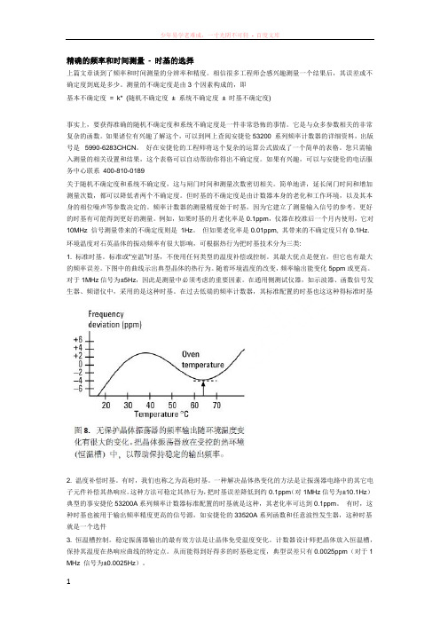
但如果老化率是0.01ppm, 其带来的不确定度只有0.1Hz. 环境温度对石英晶体的振动频率有很大影响,可根据热行为把时基技术分为三类:1. 标准时基。
标准或“室温”时基,不使用任何类型的温度补偿或控制。
其最大优点是便宜,但它也有最大的频率误差。
下图中的曲线示出典型晶体的热行为。
随着环境温度的改变,频率输出能变化5ppm或更高。
对于1MHz信号为±5Hz,因此是测量中必须考虑的重要因素。
在通用侧测试仪器,如示波器、函数信号发生器、频谱仪中,采用的是这种时基。
在过去低端的频率计数器,其标准配置的时基也这这种得标准时基2. 温度补偿时基。
- 1、下载文档前请自行甄别文档内容的完整性,平台不提供额外的编辑、内容补充、找答案等附加服务。
- 2、"仅部分预览"的文档,不可在线预览部分如存在完整性等问题,可反馈申请退款(可完整预览的文档不适用该条件!)。
- 3、如文档侵犯您的权益,请联系客服反馈,我们会尽快为您处理(人工客服工作时间:9:00-18:30)。
4.3 英寸(109.22 mm) 大型彩色图形显示屏, 将测试、运算和分析结果清晰的显示出了, 让工程师一目了然
● 数字显示
● 图形显示 - 显示趋势线、条形图和直方图 以及游标, 视图可以缩放以便您观察所需的 数据。使用游标, 您可以从趋势图和直方图 中读取特定的测量值。彩色极限线使您可以 自定义合格/不合格界限,当测量结果超过 设定定阈值后, 您可以从前面板上轻松看到。
更多样化的连通性
● LAN 接口,LXI-C ● USB 2.0 接口 ● U盘存储器插口 ● 可选 GPIB 接口 ● 支持便携工作的电池选件 ● 出色的时基精度和稳定性
更强大的测量功能 (53230A 的独特优势)
● 连续无间隙的测量 ● 调制域分析 (MDA) 的基本功能和时
间戳 ● 可选的脉冲微波测量
内置帮助系统可为您了解 所需功能提供快速指导
USB 存储器 端口可为 1 M 读数内部存储 器提供有益 补充
一般特征 预热时间 显示屏
用户界面和帮助语言 工作台尺寸 机架安装尺寸 重量 工作温度 电源 接口
电池技术 (选件 300) 包括的附件
所有型号 45 分钟 4.3 英寸 (109.22 mm) 高分辨率、高亮度彩色 TFT WQVGA (480 x 272) 显示屏, LED 背光 英文、德文、法文、日文、简体中文、韩文 261.1 mm 宽 x 103.8 mm 高 x 303.2mm 深 212.8 mm 宽 x 88.3 mm 高 x 272. 3 mm 深 (2U x 1/2 宽) 3.9 kg (8.6 磅), 包括全部选件 0°C 至 +55°C 100 V 至 240 V 通用输入; 50/60 Hz - 5% 至 +10%; 100 V -120 V; 400 Hz ± 10% LAN 接口, 符合 LXI-C 1.3 标准 USB 2.0 接口 (USB-TMC488 协议); GPIB 选件 400 内置锂离子电池, 包括集成的智能电池监视器和充电器 文档光盘, 其中包括用户指南、SCPI/ 程序员参考手册、编程实例、驱动程 序 (IVI-COM、LabView) 和 IO 程序库说明书 电源线, 2 m USB2.0 校准证书和 1 年期标准保修
数学运算 统计
平均值、标准偏差、最大值、 最小值、峰峰值、计数
平滑 (读数移动平均数)、定标、∆ 变化、空 平均值、标准偏差、最大值、最小值、峰峰值、计数、艾伦偏差
图形显示
数字、趋势、直方图、极限测试、游标
存储器
易失性读数存储器: 1 M 个读数 (16 MB); 数据记录 (自动将采样结果保存到存储器中) 保存和调用用户可定义的仪器设置; USB 文件系统
Agilent 53200 系列 射频和通用频率 计数器 / 计时器
产品系列概览
“我从未想到过频率计数器的功能如此众多, 速度如此迅捷。”
出色的速度、分辨率和精度, 但这仅仅是开始
Agilent 53200 射频和通用频率计数器 / 计时器的 过人之处在于:
更高带宽
● 350 MHz 基带频率 ● 6 GHz 或 15 GHz 可选微波通道
连续无间隙测量 (53230A) 支持基本的调制域分析功能。选择采样数 (高达 1 M 样 本) 或时间 (高达100,000秒), 连续收集一批测量结果, 针对 (该次猝发/选通) 每个 规定数量的事件添加成对时间差的时间戳。在所有通道上均可执行这种功能, 每次只能在一个通道上执行。
先进触发功能, 用于根据时间或 事件发出选通开始、选通停止、 选通抑制和选通时延命令
1 ms - 1000 s (10 µs) 无
100 µs - 1000 s (10 µs)
1 µs - 1000 s (1 µs)
信号源: 内部 / 外部 / 未使用的标配输入通道 斜率: 正 / 负; 根据时间或事件 (边沿) 进行时延和抑制
内部、外部、总线
ห้องสมุดไป่ตู้
触发数和采样数 / 触发
1 至 1,000,000
● 每次触发连续采集所有样本,读数 之间没有时延,并加入时间戳以便 进行更深入的稳定性分析
53200 系列能够帮助您: 执行和分析高精度抖动和漂移测量和 分析,而无需实际投入大量资金
无论是在较长时间内执行低速高 度精确的测量,还是在较短时间内执 行高速测量,您都可以使用 Agilent 53200系列频率计数器作为经济型、高 精度的抖动和漂移分析解决方案 (图2):
相位、总和
相位、总和、时间戳 /MDA
脉冲 / 猝发微波测量选件 150
选通特性 信号源
无 时间、外部
无
载波频率、载波周期、脉冲重复
间隔 (PRI)、脉冲重复频率 (PRF)、
正脉宽、负脉宽
时间、外部、先进(选通开始、停止 / 抑制时间或事件)
选通时间 (步长) 先进: 选通开始、停止和抑制
触发特性 信号源
应用:
晶体振荡器元器件
应用:
通信设备
应用:
雷达设备
53230A 能够帮助您: 轻松观察一段时间内的时钟稳定性
利用连续/无间隙测量和时间戳 来测量时钟在一段时间内的稳定性。 通过一系列测量观察艾伦偏差 (Allan Deviation) 中的变化。(图 1)
● 使用绘图和内置分析功能对测量数 据进行持续分析
与 Agilent 531xxA 频率计数器轻松兼容
选择53131A / 53132A / 53181A 系列兼容模式,可以在 SCPI 方面 与安捷伦以前产品完全兼容。 GPIB 连通性选件使您可以充分利 用现有 8 的 Agilent 531xxA 计数器 程序。
每种型号中都标配的 TCXO 时基, 选件可升级到超高稳 定度OCXO 时基以提供更高 精度, 或锁定到您自己的外 部时基参考。 电池选件支持连续 保持时基温度
± 0.2 ppm(典型值) ± 1 ppm
± 0.3 ppb (典型值) ± 10 ppb ± 50 ppb
± 1 ppm
± 5 ppb
内部、外部、自动
1 kΩ, AC 耦合 100 mVrms 至 2.5 Vrms 10 MHz、5 MHz、1 MHz ±1 ppm (使用选件 010 U-OCXO 时基时为 ±0.1 ppm)
53230A
350 MHz, 12 位 / 秒,
350 MHz, 12 位 / 秒,
100 ps 通用频率计数器 / 计时器 20 ps 通用频率计数器 / 计时器
通道 1: DC -350 MHz
通道 1 和通道 2: DC -350 MHz
阻抗, 耦合
可选 1 MΩ ± 1.5% 或 50 Ω ± 1.5% || < 25 pF; 可选 DC 或 AC 耦合
● 频率/周期(所有型号): 频率、频率比、周期、单一周期、脉冲/猝发测量(53230A)
● 时间间隔(53220A/53230A): 时间间隔、上升时间 /下降时间、占空比、 脉宽、相位
● 总和 (53220A/53230A)
● 电压电平 (所有型号)
可选脉冲微波测量 (53230A): 猝发载波频率、脉冲重复周期 (PRF)、脉冲重复间隔 (PRI)、脉宽
更高的分辨率和测量速度
● 12 位 /秒频率测试分辨率 ● 20 ps 单次时间间隔分辨率 ● 75,000 个频率读数 /秒,90,000 个
时间间隔读数 /秒测试速度 ● 高达 1 MSa/s 无间隙频率/时间戳
更卓越的分析和显示能力
● 数据记录趋势图 ● 累积直方图 ● 内置数学分析和统计功能 ● 1 M 读数存储器
● 数学运算功能
● 内置统计和分析功能
● 新的数据记录功能 能够以75,000个读数/秒 的速度将采样结果自动保存到非易失性存储 器中 (75MB 容量, 最多存储 5 M 个读数)。读 数可通过 LAN 或 USB 接口从存储器传输到 仪器中, 在 2 s 内最快可传输 1 M 个读数。
轻松使用您的基本测量功能:
GPIB 选件支持 系统与 531xxA 计数器兼容。
高速 USB 2.0 连通性
可选的后输入端输入
用于远程接入的 LXI-C/LAN 以太网连通性接口
特性和技术指标简介 *
输入 标配通道 (选件 201 增加了并行后面板输入)
53210A 350 MHz, 10 位 / 秒射频计数器
53220A
● 更容易使用
● 成本更低
● 使用数学运算功能分析测量结果:
平均值、标准偏差、艾伦偏差
(Allan Deviation) 等
图 1.
图 3.
脉宽 (τ) 脉冲重复周期 (T)
图 2.
Agilent 53200 系列射频和通用频率计数器 /计时器
在研发和制造阶段,工程师必须 使用高性能的频率计数器,以实现最 快速、最精准的频率和时间间隔测 量。凭借安捷伦在时间和频率测量方 面数十年的经验,53200系列射频和通 用频率计数器/ 计时器可以为您提供 最全面的信息、最出色的连通性和新 测量功能,同时提供卓越的测量速度 和精度。目前已上市的三个型号能够 在 1 秒的时间门中 提供高达 12 位/秒 的单次频率分辨率。单次时间间隔测 量的分辨率可达到 20 ps。
● 查看批量数据的直方图
● 通过一系列测量查看频率的趋势和 变化
● 使用游标查看特定的数据点
53230A 能够帮助您: 减少发射信号中的误码
现在,您可以通过一种低成本的 方法来验证发射信号的精度,增强您 对目标数据正确性的信心。使用 Agilent 53230A通用频率计数器/ 计时 器执行高分辨率脉冲/ 猝发微波频率 测量 (图 3),包括载波频率、PRI、PRF 和 PW。与其他脉冲射频测量解决方 案相比,53230A:
