NDT-03C中文资料
TS-03C发射机开机监控原理及故障剖析

2年8( 7 ) f南专 。 第期总 2 鸯 ● 1 。 第期 ' 穗
样信 号接入的 U 2 C 为高电平 , 10 ̄ 若检测不在 3 01- 0 低 电平 , 8 ( 41 %) 封锁主 电源输 出。 上述监控均正常时 , 10  ̄输 出 U 2C
摘
要 :T 一 3 中波 发 射 机 监 控 系统 的 功 能就 是 管 理 发 射 机 的 运 行 , 它是 发 射 S 0C
机 的 大脑 。它 的核 心元 件 采 用 集 成运 放 、 成 逻 辑 电路 , 些 元件 耐 压低 , 击性 差 , 集 这 抗 容
易损坏 。本 文就监 控 系统对 T 一 3 中波发射 机的开机过程 的监控 原理进行 分析 , S 0C 对
“
一
侣V 、+ 4 、 门开关 1 、 门开关 2 、 外部联 锁” ” “ 2 V” “ ”“ ”“ 的指示灯均 为绿色 ; 当合 “ 电源 ” 主 开关后 , 主
电源 ( 4 V) 一10 开始 工作 , 射 机 中间 放 大 器 工 作 ,推 动 电压 表 ” “ 动 电流 表 ” 指 示 : 合 “ 出 ” 发 “ 、推 有 当 播 开
析方法和处理措施可供业内人士参考。
二 、 机 监 控 原 理 分 析 开 ( )S 0 C 发 射 机 的 开 机 步 骤 一 T 一3 30 8 V交 流 电压 从 稳 压 配 电柜 接 入 发 射 机 , 射 机 控 制 面板 上 的 “ 制 方 式 ” 置 于 “ 控 ” “ 发 控 应 手 或 遥 控 ” 置 。 合 上 “ 压 ” 关后 , 压 电源 工 作 , 常 时 , 射 机 控 制 面 板 上 “ 8 V”“ 2 、 + V 、 位 当 低 开 低 正 发 3 0 、+1V” “ 侣 ”
短中波双色碲镉汞红外探测器制备研究

文章编号:1672-8785(2021)02-0001-07膨中波双色(镉汞红外探测器制备研究王经纬李忠贺高达邢艳蕾王成刚(华北光电技术研究所焦平面事业部,北京100015)摘要:报道了基于分子束外延的短/中波双色碼镉汞材料及器件的最新研究进展&采用分子束外延方法制备出了高质量的短/中波双色>镉汞材料,并通过提高材料质量将其表面缺陷密度控制在300cm=2以内。
在此基础上进一步优化了芯片制备工艺,尤其是在减小像元中心距方面作了优化&基于上述多项材料及器件工艺制备出了320X2569/:波双色>镉汞红外探测器组件&表明,该组件的测及成像。
关键词:>镉汞;短/中波双色;红外探测器;分子束外延中图分类号:TN213文献标志码:A DOI:10.3969/j.issn.1672-8785.2021.02.001Research on Fabrication of S3MW Dual-bandMCT Infrared DetectorsV\ANG Jing-wei,8Zhong-he,GAO Da,XING Yan-lei,W\NG Cheng-gang(.Department of Focal Plane Arrays,North China Research Institute ofElectro-Optics,Beijing100015,China)Abstract:The latest research progress of SQ/MW dual-band mercury cadmium telluride(MCT)materials and devices based on molecular beam epitaxy(MBE)is reported.High-quality SW/MW dual-band MCT materials are grown by the MBE method,and the surface defect density is controlled below300cm2by improving the material quality.On this basis,the chip fabrication process is further optimized,especially in terms of reducing the pixel pitch.A320X256SW/MW dual-band MCT infrared detector assembly is fabricated based on the a-bove-mentionedvariousmaterialanddeviceproce s es1Theresultsshowthatthetestperformanceandimaginge f ectofthea s emblyaregood1Key words:HgCdTe;SW/MW dual-band;infrared detector;molecular beam epitaxy0引言随着红外探测器应用范围的不断扩展和红外隐身技术水平的日益提高,人们期望在更为复杂的背景及环境下实现高精度的高速红外探测,同时提高识别准确率。
NACE TM0103—2003湿H2S用钢板耐SOHIC性能评估的实验室试验程序标准试验方法(中文翻译版)
NACE TM0103—2003湿H2S用钢板耐SOHIC性能评估的实验室试验程序标准试验方法(中文翻译版)本NACE国际标准代表了已审查本文件、其范围和条款的个别成员的共识。
本标准的通过并不意味着任何人—无论其是否采用本标准—在制造、销售、采购或使用产品、工艺或程序必须符合本标准。
本NACE国际标准中的任何内容均不得解释为通过暗示或其他方式授予任何权利,以制造、销售或使用与专利证书所涵盖的任何方法、装置或产品有关的任何方法、装置或产品,或赔偿或保护任何人免受专利证书侵权的责任。
本标准代表最低要求,不应解释为对使用更好的程序或材料的限制。
本标准也不适用于与主题相关的所有情况。
不可预见的情况可能会否定本标准在特定情况下的有用性。
NACE国际对其他方对本标准的解释或使用不承担任何责任,仅对NACE国际根据其管辖程序和政策发布的官方NACE国际解释承担责任,这些程序和政策禁止个人发布解释志愿者。
本NACE国际标准的用户在使用前负责审查适当的健康、安全、环境和法规文件,并确定其适用性。
本NACE国际标准可能没有列出在本标准范围内详述或提及的材料、设备和/或操作相关的所有潜在健康和安全问题或环境危害。
本NACE国际标准的用户还应负责制定适当的健康、安全和环境保护措施,必要时与适当的监管机构协商,以便在使用本标准之前达到任何现行适用的监管要求。
警告:NACE国际标准接受定期审查,可随时修订或撤销,恕不另行通知。
NACE国际要求在不迟于首次发布之日起五年内对标准进行重申、修订或撤销。
用户应注意获取最新版本。
NACE 国际标准的购买者可通过联系NACE国际会员服务部(地址:1440 South Creek Dr.,德克萨斯州休斯顿77084—4906)(电话+1(281)228—6200)获得所有标准和其他NACE国际出版物的最新信息。
批准日期:2003—01—17美国腐蚀工程师协会South Creek路1440号德克萨斯州休斯顿77084—4906+1(281)228—6200ISBN 1—57590—161—7@2003年,NACE国际前言焊接压力容器中使用的碳钢板在暴露于湿H2S环境中可能会受到一种或多种形式环境开裂的影响。
DNV-OS-C401(2010) 中文版(DNT部分)

2013年4月SECTION 3 NON-DESTRUCTIVE TESTING第三章无损检测1.General 通则1.1 Scope 范围1.1.1 This section gives requirements for non-destructive testing.本章节给出了无损探伤的要求。
2. Non-Destructive Testing (NDT) 无损探伤测试(NDT)2.1General 通则2.1.1Prior to commencement of fabrication the contractor shall submit a plan for NDT, NDT proce dures and documents for NDT inspectors’ certification for acceptance by the purchaser. The progr amme shall contain information and documents for planning, controlling and reporting在装配前,卖方必须向买方递交NDT 图,NDT 工艺文件以及NDT人员资格证,并经卖方接受。
这个程序必须包括计划、控制和报告DNT 的信息和文件。
2.1.2 The inspection categories shall be defined in accordance with DNV-OS-C101 Sec.4 or DNV-O S-C201 Sec.4 and shall be specified in relevant design drawings.检测类别应根据DNV-OS-C101第四节或DNV-OS-C201第四节来划分,并指定相关图纸。
2.1.3Welds shall be subject to NDT in progress with fabrication. The results of these activities shal l be consecutively reported to the purchaser.在制造过程中,焊缝质量主要依据无损探伤试验,试验结果应不断报告给买方。
碳氢氧元素分析仪器

碳氢氧元素分析仪器碳氢元素分析仪,碳氢氧分析仪器等主要技术指标:碳氢氧元素分析仪是高准确度、高灵敏度的有机高分子电化学传感器。
采用先进的单片微机控制技术和测量芯片,可以直接测出土壤样品中有效态含量。
该产品不仅适用于工业场所环境的检测,也可作为一般实验室用的废水污染物总量检测。
产品符合GB/ T18456-1997的要求。
其技术指标均达到或优于国际同类产品水平,具有非常广阔的市场前景。
产品符合《固体废弃物试验方法》( GB/ T30378.1)。
由上海航空电源研究所提供,实现了智能化操作及系统管理。
自动采集数据,并对测量数据进行处理、计算、打印;软件界面友好、易操作、维护简便。
该产品整套设备从材料采购至出厂调试,各个环节严格按照质量保证体系要求进行,充分体现出生产过程中的严肃性、科学性与规范性。
本公司承诺:严把质量关,做到“人无我有,人有我优”。
碳氢元素分析仪测试快速简单,广泛应用于各种实验室或企事业单位。
可在较短的时间内为您的试验结果作出正确判断!碳氢元素分析仪的作用就是能够监测某些矿石、土壤、沙尘、淤泥、石油化工废液以及残渣排放中的碳氢元素含量的一种分析仪器。
主要用途是确认化工排泄物是否被小型金属或者矿藏所吸收或存留,从而达成防止地下水污染的目的。
碳氢元素分析仪的特点是快速检测、简易、准确度高、使用寿命长、无二次污染等优点。
在分析时,将待测土壤浸入盛有指示剂的锥形瓶里(指示剂采用硼酸钠溶液),盖紧塞子,向锥形瓶内加入少许已知浓度的硼酸钠溶液,摇匀,然后用标准曲线法,直接测得样品溶液的吸光度值。
最后再换算出土壤中碳氢元素的含量。
可根据用户需要配备上位机( PC 机),实现对碳氢元素含量的计算、显示、储存、打印等功能。
还可以通过专门开发的分析软件对样品数据进行分析,并且对所获取的结果可以用 EXCEL、 WORD、 EXCBWER 等文档进行保存,然后打印输出。
碳氢元素分析仪具有很多突出的优势。
在目前我们对环境监测手段仍停留在快速监测阶段的情况下,碳氢元素分析仪因为其优异的特性受到了越来越多的青睐,被越来越多的用户所接受。
宝云兴业科贸 专业空气测计仪器 产品说明书

北京宝云兴业科贸有限公司成立于1998 年,自成立伊始,就秉持着“诚信、执着、创新、快速”的经营理念。
公司以国家相关标准为依据,引进国际先进仪器,以个性化配置方案与完善的服务体系为特色,先后成为国家卫生健康委员会、中国各省市疾控中心、卫生监督所等企事业单位的优质合作伙伴。
连续多年被推举为中国卫生监督协会环境卫生与健康专业委员会副主任委员单位,以及北京教育装备行业协会会员单位。
典型用户:国家卫生健康委员会、浙江省、福建省、安徽省、广西壮族自治区、江西省、辽宁省、河北省卫生厅、中国疾控中心、北京市疾控中心以及各省市卫生监督所、大专院校等单位。
美国TSI 公司成立于1961年,它是全球精密测量仪器设计和生产的行业领导者,出品的室内空气质量检测仪、颗粒物检测仪等都在国际上享有盛誉。
Sun Nuclear 成立于1984年,由一支经验丰富的辐射检测科学家和工程师队伍组成。
公司旨在为社会提供了一种新的测量辐射的方法,在提高了测量质量的同时也简化程序。
Mesalabs 股份有限公司是一家研发、制造及销售为一体的综合型企业,总部位于美国科罗拉多州的丹佛市。
公司主要产品包括监测仪器,数据采集仪器,气体流量校准仪器,环境监测仪及耗材等,仪器广泛应用于工业、实验室及环保等相关领域。
公司简介成功案例合作伙伴COMPANY PROFILESUCCESSFUL CASESPARTNERS美国SKC 公司是世界上最大的空气采样器制造商,是世界空气采样技术的领跑者,距今已有近60年的发展历史。
它向全球用户提供600种以上专业的空气采样产品。
日本理研计器株式会社成立于1939年,是日本知名的上市公司,也是日本首屈一指的气体测试仪器生产商,产品畅销于全球五大洲。
其生产的 FP-30MK2(C)甲醛检测仪,检测方法已被列为中国国标检测方法。
手动采样泵&检气管风速/新风量检测仪甲醛检测仪大气压力表射线检测仪水质检测套装空气采样泵流量校准器温湿度计振动测试仪细菌/病毒微生物采样系统差压计气体检测仪集中空调采样设备便携式B超检测仪在线监测系统采样附件颗粒物检测仪照度计热辐射检测仪撞击式空气微生物采样器室内空气质量检测仪测氡仪噪声检测仪水质检测仪061317263549 01082532 061520273655 05092633 0716252937产品手册 目录THE WHOLE INDUSTRYPRODUCT MANUALS01便携式采样泵(5-5000mL/min)产品特点AirChek Connect 型AirChek Connect 型便携式采样泵可通过蓝牙和USB 两种方式连接手机和电脑的低噪声采样泵。
中文力士乐03系列DKC伺服驱动器参数手册

德国力士乐伺服驱动器参数说明书
ECODRIVE03 设备一般自动化 本机具有串行实时通信系统,模拟和并行接口。
版权所有
INDRAMAT 有限公司,1999 传输,以及本文件复制,商业 使用或将其内容不得沟通无 明确的书面许可。违反这些规定将要求 赔偿。为实施专利或者发行版权所有 注册外观设计。 (德国工业标准 34-1) 保留所有权利就这个文件的内容 和可用性的产品。 INDRAMAT 有限公司· Bgm.,博士,纳贝尔- STR 基因。 2 ·的 D – 97816 加尔各答 电话 09352/40-0 ·发送 689421 ·传真 09352/40-4885 部完(OS/TH) 本文件印在无氯漂白纸。
前言
本说明书由 779K 于 2010 年 11 月 15 日用谷歌翻译 系统完成翻译,对于翻译之准确不做保证,仅供各位同 行在不急需时参考。在本说明书的后半部分,附有英文 原版说明书,如遇到不能理解之词汇,读者可以再次翻 译更正。翻译此说明书耗时 30 多小时,时间匆促,书中 错误部分希望各位同仁继续更正发布,因为目前参数中 文说明书网上基本没有。
有效期
出版
注意:
总结文件 - 概述
Hale Waihona Puke 内容1 一般资料 1-1 使用本手册............................................... ................................ 1-1 定义................................................. ............................................ 1-2 2 月 2 日至 1 日
DIN_EN_10228-3-锻件探伤-中文版

DIN EN 10228-3标准钢质锻件的NDT内容页码前言 21.范围 32.标准 33.定义 34.协定项目 45.成文程序 46.人员资质 57.设备以及附件 58.日常校合及检查 69.制作阶段 610.表面状况711.敏感度712.扫描813.分类1114.记录级别以及接受标准1415.尺寸1616.报告16附录A 环向剪波扫描最大测试深度。
B 有关%DAC的波幅前言本欧洲标准由ECISS/TC28 钢制锻件技术委员会编制。
在欧洲标准中已标明了某一国家标准的状况,要么以1998年11月最新版的同样原文,要么以背书的形式标明,如与国家标准冲突,将在1998年11月撤消。
其他部分的欧洲标准为:PART1:磁粉探伤PART2:PT(着色探伤)PART4:奥氏体以及奥氏体-铁素体不锈钢锻件超声波探伤。
根据CEN/CENELEC内部规定,下列国家的标准机构使用在欧洲标准:.奥地利比利时丹麦芬兰法国德国希腊冰岛爱尔兰意大利卢森堡公国荷兰挪威葡萄牙西班牙瑞典瑞士和英国1.范围EN10228-3 描述了使用的技术指南,铁素体以及马氏体锻件的超声波探伤,机械扫描技术,如可能使用油浸测试,但是需要买卖双方进行协商。
EN10228-3适用于四类锻件,按锻件的形状以及生产方法进行分类,1、2、3类为基本简单形状的锻件,4类覆盖了复杂形状的锻件。
EN10228-3不适用于:----模锻件----涡轮叶片以及发动机锻件。
奥氏体以及奥氏体-铁素体不锈钢锻件超声波探伤适用于本标准的PART42.标准EN10228-3由过期或不过期的标准以及其他出版物的规定组成,在正文的相应地方引用了下列的标准以及出版物:对于过期的标准,只有当本规范由修改或更新的标准组成时,随后的修改或这些修改版本的出版物将适用于本规范。
对于未过期的标准,最新的版本适用于本规范。
EN473 NDT人员资质PrEN 12668 NDT-UT设备的特性以及核实PART1:设备PART2:探头PART3:组合设备PrEN583 UT检验PART2:敏感度以及范围设置PART5:特性以及不连续的尺寸PrEN12223 UT检验-校合块PrEN1330 NDT-术语PART4:使用在UT中的术语。
asntlevel3学习资料中文

ASNT III级学习资料(中文)第一章人员资格鉴定及认证的管理................................ 错误!未定义书签。
第二章推荐性实施细则SNT-TC-1A ................................ 错误!未定义书签。
SNT-TC-1A的历史............................................... 错误!未定义书签。
SNT-TC-1A的内容及使用......................................... 错误!未定义书签。
2001版SNT-TC-1A综述.......................................... 错误!未定义书签。
SNT-TC-1A前言................................................. 错误!未定义书签。
SNT-TC-1A的1、2、3部分 ....................................... 错误!未定义书签。
SNT-TC-1A第1部分的问题 ....................................... 错误!未定义书签。
SNT-TC-1A第2、3部分的总体评论 ................................ 错误!未定义书签。
SNT-TC-1A第4部分............................................. 错误!未定义书签。
SNT-TC-1A第4部分问题......................................... 错误!未定义书签。
SNT-TC-1A第4部分的总体评论 ................................... 错误!未定义书签。
SNT-TC-1A第5部分............................................. 错误!未定义书签。
浅析TS-03C发射机三相电源监测电路原理及故障分析处理
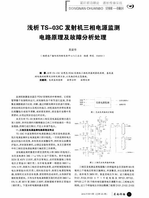
一
超 出所 指示 的范围 , 本机 将发 出报警信号 , 同时 发出故 障保
护指示 , 并封 锁发 射 机 , 以保 证 设 备免 受损 坏 。本 文 主 要 对 其
中 的 三 相 交 流 电源 监 测 进 行 阐述 其 工 作 原 理 。
该 电 路 监 测 对 象 是 外 部 交 流 供 电三 相 3 8 0 V 的 线 电压 ,
一
. I I 一
图 1 交流 电 源监 测 方 框 图
深入剖析 , 并 对 出现 的 问题 根 据 自 己 的工 作 经 验 提 出 一 些 应 急措施 , 供 同行 进 行 探 讨 , 不 足 之 处请 予 指 正 。
一
、
三相 交流 电源 监测 电 路 原 理 及 特 点
T S 一 0 3 C 中 波 发 射 机 的 电源 监 测 由 三 相 交 流 电 源 监 测 、 低 压 电源 监 测 和 主 电源 监 测 三 部 分组 成 。一 旦 所 监 测 的 电压
送 到 上 限 电压 比较 器 U 1 O 1 A, 由隔 离 电阻 R 1 0 4 、 R 1 0 5 、 R 1 0 6 封锁。 送 到 下 限 电压 比较 器 U 1 O 1 C。低 功 耗 电压 比较 器 L M3 3 9由
图 2中 U1 1 6 A为 与 门 , 它 的 逻辑 关 系 为 F : A・ B, 即无 论 U1 0 1 A 及 U1 O 1 C组 成 , U1 0 1 A 用 于 电压 上 限 监 测 , U1 0 1 C U1 1 6 A 的“ 1 l , 端或“ 2 ” 端 只 要 有 一 个 为低 电平 , 那 么输 出“ 3 ” 用 于 电压 下 限监 测 。 上 限监 测 的 U 1 O 1 A同相端( 5脚 ) 由 电源 端 就 一 定 为低 电平 , 保 证 了 电路 中 无论 是 电压 超 出 上 限 还 是
KL03 芯片系列参考手册说明书

KL03 Sub-Family Reference Manual Supports: MKL03Z8VFG4(R), MKL03Z16VFG4(R), MKL03Z32VFG4(R), MKL03Z32CAF4R, MKL03Z8VFK4(R),MKL03Z16VFK4(R), and MKL03Z32VFK4(R)Document Number: KL03P24M48SF0RMRev 3, June, 2014ContentsSection number Title PageChapter 1About This Document1.1Overview (27)1.1.1Purpose (27)1.1.2Audience (27)1.2Conventions (27)1.2.1Numbering systems (27)1.2.2Typographic notation (28)1.2.3Special terms (28)Chapter 2Introduction2.1KL03 sub-family introduction (29)2.2Module functional categories (29)2.2.1ARM Cortex-M0+ core modules (30)2.2.2System modules (31)2.2.3Memories and memory interfaces (32)2.2.4Clocks (32)2.2.5Analog modules (32)2.2.6Timer modules (33)2.2.7Communication interfaces (33)2.2.8Human-machine interfaces (34)2.3Module to module interconnects (34)2.3.1Interconnection overview (34)2.3.2Analog reference options (35)2.4Orderable part numbers (36)Chapter 3Core Overview3.1ARM Cortex-M0+ core introduction (37)3.1.1Buses, interconnects, and interfaces (37)3.1.2System tick timer (37)3.1.3Debug facilities (37)3.1.4Core privilege levels (38)3.2Nested vectored interrupt controller (NVIC) (38)3.2.1Interrupt priority levels (38)3.2.2Non-maskable interrupt (38)3.2.3Interrupt channel assignments (38)3.3AWIC introduction (41)3.3.1Wake-up sources (41)Chapter 4Memory and Memory Map4.1Flash memory (43)4.1.1Flash memory map (43)4.1.2Flash security (44)4.1.3Flash modes (44)4.1.4Erase all flash contents (44)4.1.5FTFA_FOPT register (44)4.2SRAM (45)4.2.1SRAM sizes (45)4.2.2SRAM ranges (45)4.2.3SRAM retention in low power modes (46)4.3System Register file (46)4.4Memory map (47)4.4.1Introduction (47)4.4.2System memory map (47)4.4.3Flash memory map (48)4.4.4SRAM memory map (48)4.4.5Bit Manipulation Engine (49)4.4.6Peripheral bridge (AIPS-Lite) memory map (49)4.4.7Private Peripheral Bus (PPB) memory map (54)Chapter 5Clock Distribution5.1Introduction (55)5.2Programming model (55)5.3High-level device clocking diagram (55)5.4Clock definitions (56)5.4.1Device clock summary (57)5.5Internal clocking requirements (59)5.5.1Clock divider values after reset (59)5.5.2VLPR mode clocking (60)5.6Clock gating (60)5.7Module clocks (60)5.7.1PMC 1-kHz LPO clock (61)5.7.2COP clocking (62)5.7.3RTC clocking (62)5.7.4RTC_CLKOUT and CLKOUT32K clocking (63)5.7.5LPTMR clocking (63)5.7.6TPM clocking (64)5.7.7LPUART clocking (64)Chapter 6Reset and Boot6.1Introduction (67)6.2Reset (67)6.2.1Power-on reset (POR) (68)6.2.2System reset sources (68)6.2.3MCU resets (71)6.2.4RESET pin (72)6.3Boot (72)6.3.1Boot sources (72)6.3.2FOPT boot options (73)6.3.3Boot sequence (75)Chapter 7Power Management7.1Introduction (77)7.2Clocking modes (77)7.2.1Partial Stop (77)7.2.2Compute Operation (78)7.2.3Peripheral Doze (79)7.2.4Clock gating (79)7.3Power modes (80)7.4Entering and exiting power modes (82)7.5Module operation in low-power modes (82)Chapter 8Security8.1Introduction (87)8.1.1Flash security (87)8.1.2Security interactions with other modules (87)Chapter 9Debug9.1Introduction (89)9.2Debug port pin descriptions (89)9.3SWD status and control registers (90)9.3.1MDM-AP Control Register (91)9.3.2MDM-AP Status Register (92)9.4Debug resets (94)9.5Micro Trace Buffer (MTB) (94)9.6Debug in low-power modes (95)9.7Debug and security (96)Chapter 10Signal Multiplexing and Signal Descriptions10.1Introduction (97)10.2Signal multiplexing integration (97)10.2.1I/O Port control and interrupt module features (98)10.2.2Clock gating (98)10.2.3Signal multiplexing constraints (98)10.3Pinout (98)10.3.1KL03 signal multiplexing and pin assignments (98)10.3.2KL03 pinouts (100)10.4Module Signal Description Tables (101)10.4.1Core modules (101)10.4.2System modules (102)10.4.3Clock modules (102)10.4.4Memories and memory interfaces (103)10.4.5Analog (103)10.4.6Timer Modules (103)10.4.7Communication interfaces (104)10.4.8Human-machine interfaces (HMI) (105)Chapter 11Kinetis ROM Bootloader11.1Introduction (107)11.2Functional Description (108)11.2.1Memory Maps (108)11.2.2The Kinetis Bootloader Configuration Area (BCA) (109)11.2.3Start-up Process (110)11.2.4Clock Configuration (112)11.2.5Bootloader Entry Point (113)11.2.6Bootloader Protocol (114)11.2.7Bootloader Packet Types (117)11.2.8Bootloader Command API (123)11.2.9Bootloader Exit state (135)11.3Peripherals Supported (136)11.3.1I2C Peripheral (136)11.3.2SPI Peripheral (138)11.3.3UART Peripheral (140)11.4Get/SetProperty Command Properties (143)11.4.1Property Definitions (144)11.5Kinetis Bootloader Status Error Codes (145)Chapter 12Port Control and Interrupts (PORT)12.1Chip-specific PORT information (147)12.1.1GPIO instantiation information (147)12.1.2Port control and interrupt summary (148)12.2Introduction (149)12.3Overview (149)12.3.1Features (149)12.3.2Modes of operation (149)12.4External signal description (150)12.5Detailed signal description (150)12.6Memory map and register definition (151)12.6.1Pin Control Register n (PORT x_PCR n) (154)12.6.2Global Pin Control Low Register (PORT x_GPCLR) (156)12.6.3Global Pin Control High Register (PORT x_GPCHR) (157)12.6.4Interrupt Status Flag Register (PORT x_ISFR) (157)12.7Functional description (158)12.7.1Pin control (158)12.7.2Global pin control (159)12.7.3External interrupts (159)Chapter 13General-Purpose Input/Output (GPIO)13.1Chip-specific GPIO information (161)13.2Introduction (161)13.2.1Features (161)13.2.2Modes of operation (162)13.2.3GPIO signal descriptions (162)13.3Memory map and register definition (163)13.3.1Port Data Output Register (GPIO x_PDOR) (164)13.3.2Port Set Output Register (GPIO x_PSOR) (165)13.3.3Port Clear Output Register (GPIO x_PCOR) (165)13.3.4Port Toggle Output Register (GPIO x_PTOR) (166)13.3.5Port Data Input Register (GPIO x_PDIR) (166)13.3.6Port Data Direction Register (GPIO x_PDDR) (167)13.4FGPIO memory map and register definition (167)13.4.1Port Data Output Register (FGPIO x_PDOR) (168)13.4.2Port Set Output Register (FGPIO x_PSOR) (169)13.4.3Port Clear Output Register (FGPIO x_PCOR) (169)13.4.4Port Toggle Output Register (FGPIO x_PTOR) (170)13.4.5Port Data Input Register (FGPIO x_PDIR) (170)13.4.6Port Data Direction Register (FGPIO x_PDDR) (171)13.5Functional description (171)13.5.1General-purpose input (171)13.5.2General-purpose output (171)13.5.3IOPORT (172)Chapter 14System Integration Module (SIM)14.1Chip-specific COP information (173)14.2COP clocks (173)14.3COP watchdog operation (173)14.4Introduction (175)14.4.1Features (175)14.5Memory map and register definition (176)14.5.1System Options Register 1 (SIM_SOPT1) (177)14.5.2System Options Register 2 (SIM_SOPT2) (178)14.5.3System Options Register 4 (SIM_SOPT4) (180)14.5.4System Options Register 5 (SIM_SOPT5) (181)14.5.5System Options Register 7 (SIM_SOPT7) (182)14.5.6System Device Identification Register (SIM_SDID) (184)14.5.7System Clock Gating Control Register 4 (SIM_SCGC4) (186)14.5.8System Clock Gating Control Register 5 (SIM_SCGC5) (187)14.5.9System Clock Gating Control Register 6 (SIM_SCGC6) (189)14.5.10System Clock Divider Register 1 (SIM_CLKDIV1) (190)14.5.11Flash Configuration Register 1 (SIM_FCFG1) (192)14.5.12Flash Configuration Register 2 (SIM_FCFG2) (193)14.5.13Unique Identification Register Mid-High (SIM_UIDMH) (194)14.5.14Unique Identification Register Mid Low (SIM_UIDML) (194)14.5.15Unique Identification Register Low (SIM_UIDL) (195)14.5.16COP Control Register (SIM_COPC) (195)14.5.17Service COP (SIM_SRVCOP) (197)14.6Functional description (197)Chapter 15System Mode Controller (SMC)15.1Chip-specific SMC information (199)15.2Introduction (199)15.3Modes of operation (199)15.4Memory map and register descriptions (201)15.4.1Power Mode Protection register (SMC_PMPROT) (202)15.4.2Power Mode Control register (SMC_PMCTRL) (203)15.4.3Stop Control Register (SMC_STOPCTRL) (204)15.4.4Power Mode Status register (SMC_PMSTAT) (206)15.5Functional description (206)15.5.1Power mode transitions (206)15.5.2Power mode entry/exit sequencing (209)15.5.3Run modes (211)15.5.4Wait modes (212)15.5.5Stop modes (213)15.5.6Debug in low power modes (215)Chapter 16Power Management Controller (PMC)16.1Introduction (217)16.2Features (217)16.3Low-voltage detect (LVD) system (217)16.3.1LVD reset operation (218)16.3.2LVD interrupt operation (218)16.3.3Low-voltage warning (LVW) interrupt operation (218)16.4I/O retention (219)16.5Memory map and register descriptions (219)16.5.1Low Voltage Detect Status And Control 1 register (PMC_LVDSC1) (220)16.5.2Low Voltage Detect Status And Control 2 register (PMC_LVDSC2) (221)16.5.3Regulator Status And Control register (PMC_REGSC) (222)Chapter 17Miscellaneous Control Module (MCM)17.1Introduction (225)17.1.1Features (225)17.2Memory map/register descriptions (225)17.2.1Crossbar Switch (AXBS) Slave Configuration (MCM_PLASC) (226)17.2.2Crossbar Switch (AXBS) Master Configuration (MCM_PLAMC) (226)17.2.3Platform Control Register (MCM_PLACR) (227)17.2.4Compute Operation Control Register (MCM_CPO) (229)Chapter 18Crossbar Switch Lite (AXBS-Lite)18.1Introduction (231)18.1.1Features (231)18.2Memory Map / Register Definition (231)18.3Functional Description (232)18.3.1General operation (232)18.3.2Arbitration (233)18.4Initialization/application information (234)Chapter 19Low-Leakage Wakeup Unit (LLWU)19.1Chip-specific LLWU information (235)19.2Introduction (235)19.2.1Features (235)19.2.2Modes of operation (236)19.2.3Block diagram (237)19.3LLWU signal descriptions (238)19.4Memory map/register definition (238)19.4.1LLWU Pin Enable 1 register (LLWU_PE1) (239)19.4.2LLWU Pin Enable 2 register (LLWU_PE2) (240)19.4.3LLWU Module Enable register (LLWU_ME) (241)19.4.4LLWU Flag 1 register (LLWU_F1) (243)19.4.5LLWU Flag 3 register (LLWU_F3) (244)19.4.6LLWU Pin Filter 1 register (LLWU_FILT1) (246)19.4.7LLWU Pin Filter 2 register (LLWU_FILT2) (247)19.5Functional description (248)19.5.1VLLS modes (249)19.5.2Initialization (249)Chapter 20Peripheral Bridge (AIPS-Lite)20.1Introduction (251)20.1.1Features (251)20.1.2General operation (251)20.2Functional description (252)20.2.1Access support (252)Chapter 21Reset Control Module (RCM)21.1Introduction (253)21.2Reset memory map and register descriptions (253)21.2.1System Reset Status Register 0 (RCM_SRS0) (254)21.2.2System Reset Status Register 1 (RCM_SRS1) (255)21.2.3Reset Pin Filter Control register (RCM_RPFC) (256)21.2.4Reset Pin Filter Width register (RCM_RPFW) (257)21.2.5Force Mode Register (RCM_FM) (259)21.2.6Mode Register (RCM_MR) (259)21.2.7Sticky System Reset Status Register 0 (RCM_SSRS0) (260)21.2.8Sticky System Reset Status Register 1 (RCM_SSRS1) (261)Chapter 22Bit Manipulation Engine (BME)22.1Introduction (263)22.1.1Overview (264)22.1.2Features (264)22.1.3Modes of operation (265)22.2Memory map and register definition (265)22.3Functional description (266)22.3.1BME decorated stores (266)22.3.2BME decorated loads (273)22.3.3Additional details on decorated addresses and GPIO accesses (279)22.4Application information (280)Chapter 23Micro Trace Buffer (MTB)23.1Introduction (283)23.1.1Overview (283)23.1.2Features (286)23.1.3Modes of operation (287)23.2External signal description (287)23.3Memory map and register definition (288)23.3.1MTB_RAM Memory Map (288)23.3.2MTB_DWT Memory Map (301)23.3.3System ROM Memory Map (311)Chapter 24Multipurpose Clock Generator Lite (MCG_Lite)24.1Introduction (317)24.1.1Features (317)24.1.2Block diagram (317)24.2Memory map and register definition (318)24.2.1MCG Control Register 1 (MCG_C1) (319)24.2.2MCG Control Register 2 (MCG_C2) (319)24.2.3MCG Status Register (MCG_S) (320)24.2.4MCG Status and Control Register (MCG_SC) (321)24.2.5MCG Miscellaneous Control Register (MCG_MC) (321)24.3Functional description (322)24.3.1Clock mode switching (322)24.3.2LIRC divider 1 (323)24.3.3LIRC divider 2 (323)24.3.4Enable LIRC in Stop mode (324)24.3.5MCG-Lite in Low-power mode (324)Chapter 25Oscillator (OSC)25.1OSC modes of operation with MCG_Lite and RTC (325)25.2Introduction (325)25.3Features and Modes (325)25.4Block Diagram (326)25.5OSC Signal Descriptions (327)25.6External Crystal / Resonator Connections (327)25.7External Clock Connections (328)25.8Memory Map/Register Definitions (329)25.8.1OSC Memory Map/Register Definition (329)25.9Functional Description (330)25.9.1OSC module states (330)25.9.2OSC module modes (332)25.9.3Counter (333)25.9.4Reference clock pin requirements (333)25.10Reset (334)25.11Low power modes operation (334)25.12Interrupts (334)Chapter 26Flash Memory Controller (FMC)26.1Introduction (335)26.1.1Overview (335)26.1.2Features (335)26.2Modes of operation (336)26.3External signal description (336)26.4Memory map and register descriptions (336)26.5Functional description (336)Chapter 27Flash Memory Module (FTFA)27.1Introduction (339)27.1.1Features (339)27.1.2Block Diagram (340)27.1.3Glossary (341)27.2External Signal Description (342)27.3Memory Map and Registers (342)27.3.1Flash Configuration Field Description (342)27.3.2Program Flash IFR Map (343)27.3.3Register Descriptions (343)27.4Functional Description (352)27.4.1Flash Protection (352)27.4.2Interrupts (353)27.4.3Flash Operation in Low-Power Modes (354)27.4.4Functional Modes of Operation (354)27.4.5Flash Reads and Ignored Writes (354)27.4.6Read While Write (RWW) (355)27.4.7Flash Program and Erase (355)27.4.8Flash Command Operations (355)27.4.9Margin Read Commands (360)27.4.10Flash Command Description (361)27.4.11Security (375)27.4.12Reset Sequence (377)Chapter 28Analog-to-Digital Converter (ADC)28.1Chip-specific ADC information (379)28.1.1ADC0 connections/channel assignment (379)28.1.2ADC analog supply and reference connections (380)28.1.3ADC Reference Options (380)28.1.4Alternate clock (381)28.2Introduction (381)28.2.1Features (381)28.2.2Block diagram (382)28.3ADC signal descriptions (383)28.3.1Analog Power (VDDA) (384)28.3.2Analog Ground (VSSA) (384)28.3.3Analog Channel Inputs (ADx) (384)28.4Memory map and register definitions (384)28.4.1ADC Status and Control Registers 1 (ADC x_SC1n) (385)28.4.2ADC Configuration Register 1 (ADC x_CFG1) (389)28.4.3ADC Configuration Register 2 (ADC x_CFG2) (390)28.4.4ADC Data Result Register (ADC x_R n) (391)28.4.5Compare Value Registers (ADC x_CV n) (392)28.4.6Status and Control Register 2 (ADC x_SC2) (393)28.4.7Status and Control Register 3 (ADC x_SC3) (395)28.4.8ADC Offset Correction Register (ADC x_OFS) (397)28.4.9ADC Plus-Side Gain Register (ADC x_PG) (397)28.4.10ADC Plus-Side General Calibration Value Register (ADC x_CLPD) (398)28.4.11ADC Plus-Side General Calibration Value Register (ADC x_CLPS) (398)28.4.12ADC Plus-Side General Calibration Value Register (ADC x_CLP4) (399)28.4.13ADC Plus-Side General Calibration Value Register (ADC x_CLP3) (399)28.4.14ADC Plus-Side General Calibration Value Register (ADC x_CLP2) (400)28.4.15ADC Plus-Side General Calibration Value Register (ADC x_CLP1) (400)28.4.16ADC Plus-Side General Calibration Value Register (ADC x_CLP0) (401)28.5Functional description (401)28.5.1Clock select and divide control (402)28.5.2Voltage reference selection (403)28.5.3Hardware trigger and channel selects (403)28.5.4Conversion control (404)28.5.5Automatic compare function (411)28.5.6Calibration function (412)28.5.7User-defined offset function (414)28.5.8Temperature sensor (415)28.5.9MCU wait mode operation (416)28.5.10MCU Normal Stop mode operation (416)28.5.11MCU Low-Power Stop mode operation (417)28.6Initialization information (418)28.6.1ADC module initialization example (418)28.7Application information (420)28.7.1External pins and routing (420)28.7.2Sources of error (422)Chapter 29Comparator (CMP)29.1Chip-specific CMP information (427)29.1.1CMP input connections (427)29.1.2CMP external references (428)29.1.3CMP trigger mode (428)29.2Introduction (429)29.2.1CMP features (429)29.2.26-bit DAC key features (430)29.2.3ANMUX key features (430)29.2.4CMP, DAC and ANMUX diagram (430)29.2.5CMP block diagram (431)29.3Memory map/register definitions (432)29.3.1CMP Control Register 0 (CMP x_CR0) (433)29.3.2CMP Control Register 1 (CMP x_CR1) (434)29.3.3CMP Filter Period Register (CMP x_FPR) (435)29.3.4CMP Status and Control Register (CMP x_SCR) (436)29.3.5DAC Control Register (CMP x_DACCR) (437)29.3.6MUX Control Register (CMP x_MUXCR) (437)29.4Functional description (438)29.4.1CMP functional modes (438)29.4.2Power modes (442)29.4.3Startup and operation (443)29.4.4Low-pass filter (443)29.5CMP interrupts (445)29.6Digital-to-analog converter (446)29.7DAC functional description (446)29.7.1Voltage reference source select (446)29.8DAC resets (447)29.9DAC clocks (447)29.10DAC interrupts (447)29.11CMP Trigger Mode (447)Chapter 30Voltage Reference (VREF)30.1Chip specific VREF information (449)30.1.1Clock Gating (449)30.2Introduction (449)30.2.1Overview (450)30.2.2Features (450)30.2.3Modes of Operation (451)30.2.4VREF Signal Descriptions (451)30.3Memory Map and Register Definition (452)30.3.1VREF Trim Register (VREF_TRM) (452)30.3.2VREF Status and Control Register (VREF_SC) (453)30.4Functional Description (454)30.4.1Voltage Reference Disabled, SC[VREFEN] = 0 (455)30.4.2Voltage Reference Enabled, SC[VREFEN] = 1 (455)30.4.3Internal voltage regulator (456)30.5Initialization/Application Information (457)Chapter 31Timer/PWM Module (TPM)31.1Chip-specific TPM information (459)31.1.1Clock options (459)31.1.2Trigger options (460)31.1.3Global timebase (460)31.1.4TPM interrupts (460)31.2Introduction (461)31.2.1TPM Philosophy (461)31.2.2Features (461)31.2.3Modes of operation (462)31.2.4Block diagram (462)31.3TPM Signal Descriptions (463)31.3.1TPM_EXTCLK — TPM External Clock (463)31.3.2TPM_CHn — TPM Channel (n) I/O Pin (464)31.4Memory Map and Register Definition (464)31.4.1Status and Control (TPM x_SC) (465)31.4.2Counter (TPM x_CNT) (466)31.4.3Modulo (TPM x_MOD) (467)31.4.4Channel (n) Status and Control (TPM x_C n SC) (468)31.4.5Channel (n) Value (TPM x_C n V) (469)31.4.6Capture and Compare Status (TPM x_STATUS) (470)31.4.7Configuration (TPM x_CONF) (472)31.5Functional description (473)31.5.1Clock domains (474)31.5.2Prescaler (474)31.5.3Counter (475)31.5.4Input Capture Mode (478)31.5.5Output Compare Mode (478)31.5.6Edge-Aligned PWM (EPWM) Mode (480)31.5.7Center-Aligned PWM (CPWM) Mode (481)31.5.8Registers Updated from Write Buffers (483)31.5.9Output triggers (484)31.5.10Reset Overview (484)31.5.11TPM Interrupts (484)Chapter 32Low-Power Timer (LPTMR)32.1Chip-specific LPTMR information (487)32.1.1LPTMR pulse counter input options (487)32.1.2LPTMR prescaler/glitch filter clocking options (487)32.2Introduction (488)32.2.1Features (488)32.2.2Modes of operation (488)32.3LPTMR signal descriptions (489)32.3.1Detailed signal descriptions (489)32.4Memory map and register definition (489)32.4.1Low Power Timer Control Status Register (LPTMR x_CSR) (490)32.4.2Low Power Timer Prescale Register (LPTMR x_PSR) (491)32.4.3Low Power Timer Compare Register (LPTMR x_CMR) (493)32.4.4Low Power Timer Counter Register (LPTMR x_CNR) (493)32.5Functional description (494)32.5.1LPTMR power and reset (494)32.5.2LPTMR clocking (494)32.5.3LPTMR prescaler/glitch filter (494)32.5.4LPTMR compare (496)32.5.5LPTMR counter (496)32.5.6LPTMR hardware trigger (497)32.5.7LPTMR interrupt (497)Chapter 33Real Time Clock (RTC)33.1Chip-specific RTC information (499)33.1.1RTC_CLKOUT options (499)33.2Introduction (499)33.2.1Features (499)33.2.2Modes of operation (500)33.2.3RTC signal descriptions (500)33.3Register definition (500)33.3.1RTC Time Seconds Register (RTC_TSR) (501)33.3.2RTC Time Prescaler Register (RTC_TPR) (501)33.3.3RTC Time Alarm Register (RTC_TAR) (502)33.3.4RTC Time Compensation Register (RTC_TCR) (502)33.3.5RTC Control Register (RTC_CR) (504)33.3.6RTC Status Register (RTC_SR) (506)33.3.7RTC Lock Register (RTC_LR) (507)33.3.8RTC Interrupt Enable Register (RTC_IER) (508)33.4Functional description (509)33.4.1Power, clocking, and reset (509)33.4.2Time counter (510)33.4.3Compensation (510)33.4.4Time alarm (511)33.4.5Update mode (511)33.4.6Register lock (512)33.4.7Interrupt (512)Chapter 34Serial Peripheral Interface (SPI)34.1Chip-specific SPI information (513)34.2Introduction (513)34.2.1Features (513)34.2.2Modes of operation (514)34.2.3Block diagrams (515)34.3External signal description (517)34.3.1SPSCK — SPI Serial Clock (517)34.3.2MOSI — Master Data Out, Slave Data In (518)34.3.3MISO — Master Data In, Slave Data Out (518)34.3.4SS — Slave Select (518)34.4Memory map/register definition (519)34.4.1SPI Status Register (SPI x_S) (519)34.4.2SPI Baud Rate Register (SPI x_BR) (520)34.4.3SPI Control Register 2 (SPI x_C2) (521)34.4.4SPI Control Register 1 (SPI x_C1) (523)34.4.5SPI Match Register (SPI x_M) (524)34.4.6SPI Data Register (SPI x_D) (525)34.5Functional description (525)34.5.1General (525)34.5.2Master mode (526)34.5.3Slave mode (527)34.5.4SPI clock formats (529)34.5.5SPI baud rate generation (532)34.5.6Special features (532)34.5.7Error conditions (534)34.5.8Low-power mode options (535)34.5.9Reset (536)34.5.10Interrupts (537)34.6Initialization/application information (538)34.6.1Initialization sequence (538)34.6.2Pseudo-Code Example (539)Chapter 35Inter-Integrated Circuit (I2C)35.1Chip-specific I2C information (543)35.2Introduction (543)35.2.1Features (543)35.2.2Modes of operation (544)35.2.3Block diagram (544)35.3I2C signal descriptions (545)35.4Memory map/register definition (546)35.4.1I2C Address Register 1 (I2C x_A1) (546)35.4.2I2C Frequency Divider register (I2C x_F) (547)35.4.3I2C Control Register 1 (I2C x_C1) (548)35.4.4I2C Status register (I2C x_S) (549)35.4.5I2C Data I/O register (I2C x_D) (551)35.4.6I2C Control Register 2 (I2C x_C2) (552)35.4.7I2C Programmable Input Glitch Filter Register (I2C x_FLT) (553)35.4.8I2C Range Address register (I2C x_RA) (554)35.4.9I2C SMBus Control and Status register (I2C x_SMB) (555)35.4.10I2C Address Register 2 (I2C x_A2) (556)35.4.11I2C SCL Low Timeout Register High (I2C x_SLTH) (557)35.4.12I2C SCL Low Timeout Register Low (I2C x_SLTL) (557)35.4.13I2C Status register 2 (I2C x_S2) (558)35.5Functional description (558)35.5.1I2C protocol (558)35.5.210-bit address (564)35.5.3Address matching (565)35.5.4System management bus specification (566)35.5.5Resets (569)35.5.6Interrupts (569)35.5.7Programmable input glitch filter (571)35.5.8Address matching wake-up (572)35.5.9Double buffering mode (573)35.6Initialization/application information (574)Chapter 36Low Power Universal Asynchronous Receiver/Transmitter (LPUART)36.1Chip-specific LPUART information (579)36.2Introduction (579)36.2.1Features (579)36.2.2Modes of operation (580)36.2.3Signal Descriptions (581)36.2.4Block diagram (581)36.3Register definition (583)36.3.1LPUART Baud Rate Register (LPUART x_BAUD) (584)36.3.2LPUART Status Register (LPUART x_STAT) (586)36.3.3LPUART Control Register (LPUART x_CTRL) (590)36.3.4LPUART Data Register (LPUART x_DATA) (595)36.3.5LPUART Match Address Register (LPUART x_MATCH) (597)36.4Functional description (597)36.4.1Baud rate generation (597)36.4.2Transmitter functional description (598)36.4.3Receiver functional description (600)36.4.4Additional LPUART functions (605)36.4.5Interrupts and status flags (607)Chapter 1About This Document1.1Overview1.1.1PurposeThis document describes the features, architecture, and programming model of the Freescale microcontroller.1.1.2AudienceA reference manual is primarily for system architects and software application developers who are using or considering using a Freescale product in a system.1.2Conventions1.2.1Numbering systemsThe following suffixes identify different numbering systems:1.2.2Typographic notationThe following typographic notation is used throughout this document:1.2.3Special termsThe following terms have special meanings:Chapter 2Introduction2.1KL03 sub-family introductionThe device is highly-integrated, market leading ultra low-power 32-bit microcontroller based on the enhanced Cortex-M0+ (CM0+) core platform. The features of the KL03 family derivatives are as follows.•Core platform clock up to 48 MHz, bus clock up to 24 MHz•Memory option is up to 32 KB flash, 2 KB RAM and 8 KB ROM with build-in boot loader•Wide operating voltage ranges from 1.71–3.6 V with fully functional flash program/ erase/read operations•Multiple package options from 16-pin to 24-pin•Ambient operating temperature ranges from –40 °C to 85 °C for WLCSP package and –40 °C to 105 °C for all the other packages.The family acts as an ultra low-power, cost-effective microcontroller to provide developers an appropriate entry-level 32-bit solution. The family is the next-generation MCU solution for low-cost, low-power, high-performance devices applications. It’s valuable for cost-sensitive, portable applications requiring long battery life-time.2.2Module functional categoriesThe modules on this device are grouped into functional categories. Information found here describes the modules assigned to each category in more detail.2.2.1ARM Cortex-M0+ core modules The following core modules are available on this device.2.2.2System modulesThe following system modules are available on this device.2.2.3Memories and memory interfacesThe following memories and memory interfaces are available on this device.2.2.4ClocksThe following clock modules are available on this device.2.2.5Analog modulesThe following analog modules are available on this device:。
Aerofab NDT产品目录说明书

This catalog is a sample of what Aerofab NDT Offers, please contact our sales department at ********************or toll free at 844 495-9219 for any parts you do not see represented in these pages. Table of ContentsRotary and Countersink Probes (2)Pencil/Surface Probes (3)Blade Probes (4)Ring, Spot, Sliding Probes (5)Transducers.......................................................................................... 6-8 Reference Standards (9)Cables and Adaptors (10)Custom Kits (11)Aerofab NDT Offers a One Year Warranty On All PartsRotary Hole ProbesFull range rotary designs with an assortment of sizes and frequency’s.Standard working length 1.5 to 2.0, custom sizes and lengths upon request.OptionsFrequency, Connectors, Working Length, Flexible, Shielded/Unshielded, Split End, Stainless Steel Rotary Probes Adjustable Y Probes Adjustable X ProbesHocking, MiniMite & Rohman (Universal)Rechii & RA-2000 (Nortec)Hocking,MiniMite &Rohman(Universal)Rechii & RA-2000(Nortec)Hocking,MiniMite &Rohman(Universal)Rechii & RA-2000 (Nortec)AUR-.125 ARR-.125 AURY-.125-.156 ARRY-.125-.156 AURX-.187-.250 ARRX-.187-.250 AUR-.156 ARR-.156 AURY-.156-.187 ARRY-.156-.187 AURX-.250-.312 ARRX-.250-.312 AUR-.187 ARR-.187 AURY-.187-.218 ARRY-.187-.218 AURX-.312-.375 ARRX-.312-.375 AUR-.250 ARR-.250 AURY-.218-.250 ARRY-.218-.250 AURX-.375-.437 ARRX-.375-.437 AUR-.312 ARR-.312 AURY-.250-.312 ARRY-.250-.312 AURX-.437-.500 ARRX-.437-.500 AUR-.375 ARR-.375 AURY-.312-.375 ARRY-.312-.375 AURX-.500-.625 ARRX-.500-.625 AUR-.437 ARR-.437 AURY-.375-.437 ARRY-.375-.437 AURX-.625-.687 ARRX-.625-.687 AUR-.500 ARR-.500 AURY-.437-.500 ARRY-.437-.500 AURX-.687-.750 ARRX-.687-.750 AUR-.625 ARR-.625 AURY-.500-.625 ARRY-.500-.625 AURX-.750-.875 ARRX-.750-.875 AUR-.687 ARR-.687 AURY-.625-.687 ARRY-.625-.687 AURX-.875-1.0 ARRX-.875-1.0 AUR-.750 ARR-.750 AURY-.687-.750 ARRY-.687-.750AUR-.875 ARR-.875 AURY-.750-.875 ARRY-.750-.875AUR-1.0 ARR-1.0 AURY-.875-1.0 ARRY-.875-1.0Counter Sink Probes Manual Counter Sink ProbesHocking, MiniMite & Rohman (Universal)Rechii & RA-2000 (Nortec)Triax MicrodotAURCS100-.156 ARRCS100-.156 ATCS100-.156 ACSM100-.156/2M AURCS100-.187 ARRCS100-.187 ATCS100-.187 ACSM100-.187/2M AURCS100-.250 ARRCS100-.250 ATCS100-.250 ACSM100-.250/2MPencil/Surface ProbesFull range rotary designs with an assortment of sizes and frequency’s.Sta ndard working length is 5.0”, custom sizes and lengths upon request.Surface/Pencil ProbesShaft Ø Straight/Drop Connector Frequency Shielded/UN X= Extra Small 0.072 Straight Microdot 50-500KHZ S= Small 0.093 45° 45 Triax T 1-3MHZRegular 0.125 90° 95AXTPN-5 Extra Small .072, Straight, Triax Connector, 5" length, 50-500KHZAXPN-5 Extra Small .072, Straight, Microdot Connector, 5" length, 50-500KHZASTPN-5 Small .093, Straight, Triax Connector, 5" length, 50-500KHZASPN-5 Small .093, Straight, Microdot Connector, 5" length, 50-500KHZATPN-5 Regular .125, Straight, Triax Connector, 5" length, 50-500KHZAPN-5 Regular .125, Straight, Microdot Connector, 5" length, 50-500KHZAPNU-5 Regular .125, Straight, Microdot Connector, 5" length, 50-500KHZ, Unshielded APNU-5/2M Regular .125, Straight, Microdot Connector, 5" length, 1-3MHZ, UnshieldedAXTPN45-5 Extra Small .072, 45°,.500 Drop, Triax Connector, 5" length, 50-500KHZAXPN45-5 Extra Small .072, 45°, .500 Drop, Microdot Connector, 5" length, 50-500KHZASTPN45-5 Small .093, 45°, .500 Drop, Triax Connector, 5" length, 50-500KHZASPN45-5 Small .093, 45°, .500 Drop, Microdot Connector, 5" length, 50-500KHZATPN45-5 Regular .125, 45°, .500 Drop, Triax Connector, 5" length, 50-500KHZAPN45-5 Regular .125, 45°, .500 Drop, Microdot Connector, 5" length, 50-500KHZAPNU45-5 Regular .125, 45°, .500 Drop, Microdot Connector, 5" length, 50-500KHZ, Unshielded APNU45-5/2M Regular .125, 45°, .500 Drop, Microdot Connector, 5" length, 1-3MHZ, Unshielded AXTPN95-5 Extra Small .072, 90°, .500 Drop, Triax Connector, 5" length, 50-500KHZAXPN95-5 Extra Small .072, 90°, .500 Drop, Microdot Connector, 5" length, 50-500KHZASTPN95-5 Small .093, 90°, .500 Drop, Triax Connector, 5" length, 50-500KHZASPN95-5 Small .093, 90°, .500 Drop, Microdot Connector, 5" length, 50-500KHZATPN95-5 Regular .125, 90°, .500 Drop, Triax Connector, 5" length, 50-500KHZAPN95-5 Regular .125, 90°, .500 Drop, Microdot Connector, 5" length, 50-500KHZAPNU95-5 Regular .125, 90°, .500 Drop, Microdot Connector, 5" length, 50-500KHZ, Unshielded APNU95-5/2M Regular .125, 90°, .500 Drop, Microdot Connector, 5" length, 1-3MHZ, UnshieldedBlade ProbesFull range blade designs with an assortment of sizes and frequency’s.Sta ndard working length is 5.0”, custom sizes and lengths upon request.Blade ProbesShaftThickness Straight/Drop Connector FrequencyStraight Microdot 50-500KHZ0.045 45° 45 Triax T0.060 60° 600.090 90° 90ATBL045-6 Shaft Ø .045, Straight, Triax Connector, 6" LengthABL045-6 Shaft Ø .045, Straight, Microdot Connector, 6" Length ATBL060-6 Shaft Ø .060, Straight, Triax Connector, 6" LengthABL060-6 Shaft Ø .060, Straight, Microdot Connector, 6" Length ATBL090-6 Shaft Ø .090, Straight, Triax Connector, 6" LengthABL090-6 Shaft Ø .090, Straight, Microdot Connector, 6" Length ATBL445-6 Shaft Ø .045, 45° Drop, Triax Connector, 6" LengthABL445-6 Shaft Ø .045, 45° Drop, Microdot Connector, 6" Length ATBL660-6 Shaft Ø .060, 60° Drop, Triax Connector, 6" LengthABL660-6 Shaft Ø .060, 60° Drop, Microdot Connector, 6" Length ATBL990-6 Shaft Ø .090, 90° drop, Triax Connector, 6" LengthABL990-6 Shaft Ø .090, 90° Drop, Microdot Connector, 6" LengthRing, Spot, Sliding Probes Full range of designs with an assortment of sizes and frequency’s. Custom sizes and lengths upon request. Specify OD, ID, and Height when orderingRing – Low Frequency Probe – Triax Ring – Low Frequency Probe - MicrodotSpot – Low Frequency Probe – Triax Spot – Low Frequency – MicrodotSliding Surface Probe – Triax Sliding Surface Probe – MicrodotTransducersFull range of Shear Wave Transducers with an assortment of frequencies, connectors, mounts and materials. Custom designs upon requestShear Wave / Angle Beam TransducerCase Size/Dims Frequency Angle Material MicrodotConnectorOrientationExtra Small X 0.187 .375x.375x.260 2.25MHZ 35° Aluminum A Side Mount SSmall S 0.187 .550x.450x.260 5MHZ 45° Stainless Steel S Top Mount T Medium M 0.250 .750x.500x.370 10MHZ 60°Large L 0.375 1.00x.600x.500 70°Shear Wave5MHZ - Extra Small .187X.187 5MHZ - Small .187X.187AFX-545AT 45° IN AL TOP MOUNT AFS-545AT 45° IN AL TOP MOUNT AFX-545AS 45° IN AL SIDE MOUNT AFS-545AS 45° IN AL SIDE MOUNT AFX-545ST 45° IN SS TOP MOUNT AFS-545ST 45° IN SS TOP MOUNT AFX-545SS 45° IN SS SIDE MOUNT AFS-545SS 45° IN SS SIDE MOUNT AFX-560AT 60° IN AL TOP MOUNT AFS-560AT 60° IN AL TOP MOUNT AFX-560AS 60° IN AL SIDE MOUNT AFS-560AS 60° IN AL SIDE MOUNT AFX-560ST 60° IN SS TOP MOUNT AFS-560ST 60° IN SS TOP MOUNT AFX-560SS 60° IN SS SIDE MOUNT AFS-560SS 60° IN SS SIDE MOUNT AFX-570AT 70° IN AL TOP MOUNT AFS-570AT 70° IN AL TOP MOUNT AFX-570AS 70° IN AL SIDE MOUNT AFS-570AS 70° IN AL SIDE MOUNT AFX-570ST 70° IN SS TOP MOUNT AFS-570ST 70° IN SS TOP MOUNTAFX-570SS 70° IN SS SIDE MOUNT AFS-570SS 70° IN SS SIDE MOUNT 5MHZ - Medium .250x.250 5MHZ - Large .375x.375AFM-545AS 45° IN AL TOP MOUNT AFL-545AS 45° IN AL TOP MOUNT AFM-545AT 45° IN AL SIDE MOUNT AFL-545AT 45° IN AL SIDE MOUNT AFM-545SS 45° IN SS TOP MOUNT AFL-545SS 45° IN SS TOP MOUNT AFM-545ST 45° IN SS SIDE MOUNT AFL-545ST 45° IN SS SIDE MOUNT AFM-560AS 60° IN AL TOP MOUNT AFL-560AS 60° IN AL TOP MOUNT AFM-560AT 60° IN AL SIDE MOUNT AFL-560AT 60° IN AL SIDE MOUNT AFM-560SS 60° IN SS TOP MOUNT AFL-560SS 60° IN SS TOP MOUNTAFM-560ST 60° IN SS SIDE MOUNT AFL-560ST 60° IN SS SIDE MOUNTAFM-570AS 70° IN AL TOP MOUNT AFL-570AS 70° IN AL TOP MOUNT AFM-570AT 70° IN AL SIDE MOUNT AFL-570AT 70° IN AL SIDE MOUNT AFM-570SS 70° IN SS TOP MOUNT AFL-570SS 70° IN SS TOP MOUNTAFM-570ST 70° IN SS SIDE MOUNT AFL-570ST 70° IN SS SIDE MOUNT 10MHZ - Extra Small .187X.187 10MHZ - Small .187X.187AFX-1045AT 45° IN AL TOP MOUNT AFS-1045AT 45° IN AL TOP MOUNT AFX-1045AS 45° IN AL SIDE MOUNT AFS-1045AS 45° IN AL SIDE MOUNT AFX-1045ST 45° IN SS TOP MOUNT AFS-1045ST 45° IN SS TOP MOUNTAFX-1045SS 45° IN SS SIDE MOUNT AFS-1045SS 45° IN SS SIDE MOUNT 10MHZ - Medium .250x.250 10MHZ - Large .375x.375AFM-1045AS 45° IN AL TOP MOUNT AFL-1045AS 45° IN AL TOP MOUNT AFM-1045AT 45° IN AL SIDE MOUNT AFL-1045AT 45° IN AL SIDE MOUNT AFM-1045SS 45° IN SS TOP MOUNT AFL-1045SS 45° IN SS TOP MOUNTAFM-1045ST 45° IN SS SIDE MOUNT AFL-1045ST 45° IN SS SIDE MOUNT Angle Beam5MHZ - XX Small .187X.187 5MHZ - Extra Small .187X.187AFS-545AT 45° IN AL TOP MOUNT AFS-545AT 45° IN AL TOP MOUNT AFS-545AS 45° IN AL SIDE MOUNT AFS-545AS 45° IN AL SIDE MOUNT AFS-545ST 45° IN SS TOP MOUNT AFS-545ST 45° IN SS TOP MOUNT AFS-545SS 45° IN SS SIDE MOUNT AFS-545SS 45° IN SS SIDE MOUNT AFS-560AT 60° IN AL TOP MOUNT AFS-560AT 60° IN AL TOP MOUNT AFS-560AS 60° IN AL SIDE MOUNT AFS-560AS 60° IN AL SIDE MOUNT AFS-560ST 60° IN SS TOP MOUNT AFS-560ST 60° IN SS TOP MOUNT AFS-560SS 60° IN SS SIDE MOUNT AFS-560SS 60° IN SS SIDE MOUNT AFS-570AT 70° IN AL TOP MOUNT AFS-570AT 70° IN AL TOP MOUNT AFS-570AS 70° IN AL SIDE MOUNT AFS-570AS 70° IN AL SIDE MOUNT AFS-570ST 70° IN SS TOP MOUNT AFS-570ST 70° IN SS TOP MOUNTAFS-570SS 70° IN SS SIDE MOUNT AFS-570SS 70° IN SS SIDE MOUNT 5MHZ - Small .187X.187 5MHZ - Medium .250x.250AFX-545AT 45° IN AL TOP MOUNT AFL-545AS 45° IN AL TOP MOUNT AFX-545AS 45° IN AL SIDE MOUNT AFL-545AT 45° IN AL SIDE MOUNT AFX-545ST 45° IN SS TOP MOUNT AFL-545SS 45° IN SS TOP MOUNT AFX-545SS 45° IN SS SIDE MOUNT AFL-545ST 45° IN SS SIDE MOUNT AFX-560AT 60° IN AL TOP MOUNT AFL-560AS 60° IN AL TOP MOUNT AFX-560AS 60° IN AL SIDE MOUNT AFL-560AT 60° IN AL SIDE MOUNT AFX-560ST 60° IN SS TOP MOUNT AFL-560SS 60° IN SS TOP MOUNT AFX-560SS 60° IN SS SIDE MOUNT AFL-560ST 60° IN SS SIDE MOUNT AFX-570AT 70° IN AL TOP MOUNT AFL-570AS 70° IN AL TOP MOUNT AFX-570AS 70° IN AL SIDE MOUNT AFL-570AT 70° IN AL SIDE MOUNT AFX-570ST 70° IN SS TOP MOUNT AFL-570SS 70° IN SS TOP MOUNTAFX-570SS 70° IN SS SIDE MOUNT AFL-570ST 70° IN SS SIDE MOUNT 5MHZ - Large .375x.375 10MHZ - XX Small .187X.187AFM-545AS 45° IN AL TOP MOUNT AFX-1045AT 45° IN AL TOP MOUNT AFM-545AT 45° IN AL SIDE MOUNT AFX-1045AS 45° IN AL SIDE MOUNT AFM-545SS 45° IN SS TOP MOUNT AFX-1045ST 45° IN SS TOP MOUNT AFM-545ST 45° IN SS SIDE MOUNT AFX-1045SS 45° IN SS SIDE MOUNTAFM-560AS 60° IN AL TOP MOUNT 10MHZ - Extra Small .187X.187AFM-560AT 60° IN AL SIDE MOUNT AFX-1045AT 45° IN AL TOP MOUNTAFM-560SS 60° IN SS TOP MOUNT AFX-1045AS 45° IN AL SIDE MOUNT AFM-560ST 60° IN SS SIDE MOUNT AFX-1045ST 45° IN SS TOP MOUNT AFM-570AS 70° IN AL TOP MOUNT AFX-1045SS 45° IN SS SIDE MOUNT AFM-570AT 70° IN AL SIDE MOUNT 10MHZ - Small .187X.187AFM-570SS 70° IN SS TOP MOUNT AFS-1045AT 45° IN AL TOP MOUNTAFM-570ST 70° IN SS SIDE MOUNT AFS-1045AS 45° IN AL SIDE MOUNT 10MHZ - Medium .250x.250 AFS-1045ST 45° IN SS TOP MOUNT AFM-1045AS 45° IN AL TOP MOUNT AFS-1045SS 45° IN SS SIDE MOUNT AFM-1045AT 45° IN AL SIDE MOUNT 10MHZ - Large .375x.375AFM-1045SS 45° IN SS TOP MOUNT AFL-1045AS 45° IN AL TOP MOUNT AFM-1045ST 45° IN SS SIDE MOUNT AFL-1045AT 45° IN AL SIDE MOUNTAFL-1045SS 45° IN SS TOP MOUNTAFL-1045ST 45° IN SS SIDE MOUNTReplaceable Delay TransducerFrequency Element OD0.250 0.5005MHZ ARD-525 ARD-55010MHZ ARD-1025 ARD-105015MHZ ARD-1525 ARD15501.0MHZ ARD-1502.25MHZ ARD-225 ARD-2503.50MHZ ARD-325 ARD-350Fixed Delay TransducerFrequency Element OD0.2505MHZ APD-52510MHZ APD-102515MHZ APD-15252.25MHZ APD-225Dual Element Transducer -2 Pin MicrodotFrequency Element OD0.250 0.5005MHZ ADL-525 ADL-55010MHZ ADL-1025 ADL-105015MHZ ADL-1525 ADL-1550Reference Standards Full range of configurations and materials with an assortment of surface, corner and mid-wall EDM notches. Custom designs upon request.Bolt Reference Standards Hole Reference StandardsSurface Reference Standards Ultrasonic Reference StandardsCables & AdaptorsFull range of Cable and Adaptor designs and connector configurations. Standard length is 6’ custom lengths and connector configurations upon request.CablesAdaptorsRotary Scanner Adaptors11* 8629 S 212th St Kent, WA 98031 * 844-495-9219 * *Probe KitsFull range of designs with an assortment of sizes and frequency’s. Custom sizes and lengths upon request.Surface Probe Kits UT Probe Kits Low Frqeuncy Probe Kit。
无损检测NDT 知识
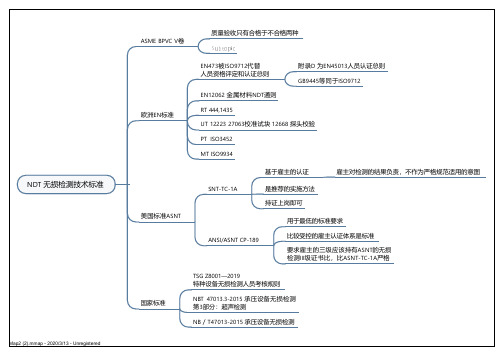
NDT 无损检测技术标准ASME BPVC V卷
质量验收只有合格于不合格两种
欧洲EN标准
EN473被ISO9712代替
人员资格评定和认证总则
附录D 为EN45013人员认证总则
GB9445等同于ISO9712
EN12062 金属材料NDT通则
RT 444,1435
UT 12223 27063校准试块 12668 探头校验
PT ISO3452
MT ISO9934
美国标准ASNT
SNT-TC-1A
基于雇主的认证雇主对检测的结果负责,不作为严格规范适用的意图
是推荐的实施方法
持证上岗即可
ANSI/ASNT CP-189
用于最低的标准要求
比较受控的雇主认证体系是标准
要求雇主的三级应该持有ASNT的无损
检测III级证书比,比ASNT-TC-1A严格
国家标准
TSG Z8001—2019
特种设备无损检测人员考核规则
NBT 47013.3-2015 承压设备无损检测
第3部分:超声检测
NB/T47013-2015 承压设备无损检测
Map2 (2).mmap - 2020/3/13 - Unregistered。
enc-03一些中文资料
∙输出型号类别: 模拟传感器
∙原理类别: 真空度传感器
∙用途类别: 速度传感器
∙材质: 金属
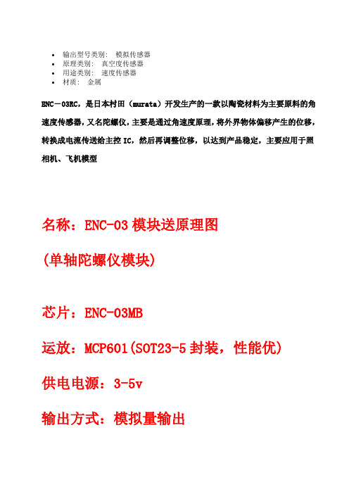
ENC-03RC,是日本村田(murata)开发生产的一款以陶瓷材料为主要原料的角速度传感器,又名陀螺仪,主要是通过角速度原理,将外界物体偏移产生的位移,转换成电流传送给主控IC,然后再调整位移,以达到产品稳定,主要应用于照相机、飞机模型
名称:ENC-03模块送原理图
(单轴陀螺仪模块)
芯片:ENC-03MB
运放:MCP601(SOT23-5封装,性能优)
供电电源:3-5v
输出方式:模拟量输出
超小尺寸:10mm* 17.5mm 提供原理图
PDF标准接法:
直接藕合接法:。
中英文-PDA TR03 干热灭菌验证

some may be subject to change in the future. However, the terms used in a validation program must be clearly defined and well understood within the company and clearly defined in internal Standard Operating Procedures (SOPs), standards, and in regulatory filings. For the purposes of this technical report, the following definitions are used. 使用的是当前FDA、 ICH以及其他管理当局的名词定义, 但技术报告团队添加上更清晰的内容这 种情况除外。可以考虑法规指南提供的其他定义。一些术语在各公司之间的使用可能是不同的, 而一些术语在未来可能会有变化。但是,验证程序中使用的术语必须清晰定义并且能够在公司 内被清楚理解,在内部标准操作规程(SOP)、标准及管理文件中也应清楚定义。本技术报告 出于这样的目的,使用如下定义。
1
术方法也可能存在并被应用,如果这些其他方法有合理的科学方法做支持。 This technical report is intended to give information about current industry practices and approaches to validating dry-heat depyrogenation and sterilization processes. In addition, sections will cover various aspects of dry-heat sterilization using biological indicators. 这份技术报告的目的是为目前工业实践以及干热除热原和灭菌工艺验证方法提供信息支持。此 外,报告的一些章节覆盖了干热灭菌使用的生物指示剂的各方面。 This technical report is organized in a chronological fashion, starting with a discussion of the general concepts of depyrogenation and sterilization science which are the foundation upon which to build a robust process. This includes use of biological indicators and endotoxin indicators. Also included are points to consider in equipment design, equipment verification, process development and performance qualification for new systems and the development and validation of processes for existing systems. 该技术报告是以时间顺序排列,以除热原和灭菌科学的通用概念开始,而这是建立稳固工艺的 基础。其中包括了生物指示剂和内毒素指示剂的使用。也包括了新系统的设备设计、设备确证、 工艺开发以及性能确认,还包括现有系统中工艺设计和验证中所需考虑的问题。 In the discussion of process development, particular attention has been given to the load type, loading patterns, and temperature profiles for depyrogenation and sterilization in both ovens and tunnels. The sections are followed by a brief discussion of items for consideration during routine processing and ongoing maintenance of the validated process. 工艺开发的讨论中,对于在烘箱和隧道中进行除热原和灭菌的负载种类、负载模式以及温度曲 线都给予特殊的关注。在已验证工艺的日常操作和持续维护中所需考虑的内容在这一部分也做 了简要讨论。 The background sections on depyrogenation/sterilization science and endotoxin/biological indicators are not comprehensive—but provide information specific to dry-heat processes. Information within the technical report is applicable to both forced hot air dry-heat batch processes (chambers) and to continuous processes (tunnels). Information within this technical report does not apply to dry-heat processes used for the sterilization of oil bases and oil based products, fixed processing streams or to those processes using infrared and microwave heating media. 关于除热原/灭菌科学和内毒素/生物指示剂的背景部分并不全面——但是所提供的信息是针对 干热工艺的。技术报告中的信息既适用于强制热空气干热批生产工艺(腔体),也适用于连续 性工艺(隧道)。本技术报告中的信息不适用于油性基质及油性基质产品,固定工艺流程或者 那些使用红外及微波加热介质的工艺中灭菌所用的干热工艺。 Current FDA, ICH, and other regulatory definitions are used except when more clarity is added by the Technical Report Team. Regulatory guidelines offer other definitions that maybe considered. Variations in the use of some terms may differ from company to company and
NDT-涡流检测(整理)
无损检测方法概述1.超声检测设备:超神探伤仪、探头、耦合剂及标准试块等用途:检测锻件裂纹、分层、夹杂,焊缝中的裂纹、气孔、夹渣、未熔合、未焊透,型材的裂纹、分层、夹杂、折叠,铸件中的缩孔、气泡、热裂、冷裂、疏松、夹渣等缺陷及厚度测定。
优点:对平面型缺陷十分敏感,一经探伤便知结果;易于携带;穿透力强局限性:为耦合传感器,要求被检表面光滑;难于探测出细小裂纹;要有参考标准,为解释信号,要求检验人员有较高的素质;不适用于形状复杂或表面粗糙的工作2.声发射检测设备:声发射传感器、放大电路、信号处理器电路及声发射信号分析系统用途:检测构件的动态裂纹、裂纹萌生及裂纹生长率等优点:实时并连续监控探测,可以遥控,装置较轻便局限性:传感器与试件耦合应良好,试件必须处于应力状态,延性材料产生低幅值声发射,噪声不得进入探测系统,设备贵,人员素质要求高3.噪声检测设备:声级计、频率分析仪、噪声分析仪用途:检测设备内部结构的磨损、撞击、疲劳等缺陷,寻找噪声源(故障源)优点:仪器轻便,检测分析速度快,可靠性高局限性:仪器较贵,对人员素质要求较高4.激光检测设备:激光全息摄影机用途:检测微小变形、夹板蜂窝结构的胶结质量、充气轮胎缺陷、材料裂纹、高速物理过程中等离子体诊断和高速碰撞等优点:检测灵敏度高、面积大、不受材料限制、结果便于保存局限性:仅适用于近表面缺陷检测5.微波检测设备:微博计算机断层成像机(微波CT机)用途:检测复合材料、非金属制品、火箭壳体、航空部件、轮胎等;还可测量厚度、密度、湿度等物理参数优点:非接触测量,检测速度快,可实现自动化局限性:不能用来检测金属导体内部缺陷,一般不适用于检测小于1mm的缺陷,空间分辨率比较低6.光纤检测设备:光纤内窥镜、光纤裂纹检测仪用途:检测锅炉、泵体、铸件、炮筒、压力容器、火箭壳体、管道内表面的缺陷及焊缝质量和疲劳裂纹等优点:灵敏度高,绝缘好,抗腐蚀,不受电磁干扰局限性:价格较贵,不能检测结构内部缺陷7.涡流检测设备:涡流探伤仪和标准试块用途:检测导电材料表面和近表面的裂纹、夹杂、折叠、凹坑、疏松等缺陷,并能确定缺陷位置和相对尺寸优点:经济、简便,可自动对准工件探伤,不需耦合,探头不接触试件局限性:仅限于导体材料,穿透浅,要有参考标准,难以判断缺陷种类,不适用于非导电材料8.X射线检测设备:X射线源(机)和电源,要有和使用Y射线源相同的设备用途:检测焊缝未焊透、气孔、夹渣,铸件中的缩孔、气孔、疏松、热裂等,并能确定缺陷的位置、大小及种类优点:功率可调,照相质量比Y射线高,可永久记录局限性:X射线设备一次投资大,不易携带,有放射危险,要有高素质的操作和评定人员,较难发现焊缝裂纹和未熔合缺陷,不适用于锻件和型材9.Y射线检测设备:Y射线探伤仪,底片夹、胶片,射线铅屏蔽,胶片处理设备,底片观察光源,曝光设备以及辐射监控设备等用途:检测焊接不连续性(包括裂纹、气孔、未熔合、未焊透及夹渣)以及腐蚀和装配缺陷。
DNA03简易操作

徕卡DNA数字水准仪简易操作手册DNA03数字水准仪简易操作手册一、基本操作1、仪器基本性能、仪器保养DNA03/10是徕卡新一代的数字水准仪,它具有以下性能特点:●中文界面,操作更容易,水准测量程序完全符合我国的国家标准,电子气泡照明;●超大显示屏,显示的内容更丰富,并有专门的字母数字输入键和面板加热功能;●采用新式标准磁阻尼补偿器,测量精度达到0.3mm/Km;●可使用徕卡编码标尺进行自动测量,也可以使用普通水准尺按照光学原理测量;●数据记录在内存中或PC卡上,内存可以记录8000个数据;●采用流线型和白色外表设计,可减少风阻和太阳辐射,并具有双侧无限位水位微动;●数据输出方式灵活,用户可以自己定制数据输出格式;●可以使用5#干电池…………等等。
仪器的保养:仪器必须装箱运输,防止受剧烈振动;仪器不宜受潮;避免在强磁场内作业,影响精度;放置温度在-40℃~+70℃;保持目镜和物镜的清洁;电池使用注意事项。
2、水准测量开机进入“水准测量”界面,该功能是用于一般的水准测量和配合“碎部点测量”和“放样”。
如图一:在输入后视点号PtID和该点的高程H0后,对该后视点进行测量,得出后视读数Back,视距Dist、视线高程Hcol,这时后视点测量完毕,光标进入按回车键,即进入前视点测量,如图二:此时显示后视点名PtBS,输入前视点名后,即可对前视点进行测量,Fore为前视读数,前视视距Dist,后视点A1到前视点A2的高差为dH,前视点的高程为H。
光标进入按回车键,即进入图一界面,此时以A2为后视,按上述步骤进行所有的水准测量。
3、徕卡数字水准仪GSI数据格式简介:徕卡GSI数据记录格式是徕卡仪器的专用记录格式,它是由字索引+测量数据构成一个测量数据块,一行记录由一个或多个数据块组成。
例子:(线路水准测量数据)410003+? (2)110004+00999906 83..16+00000000110005+00999906 32..00+00012610 331128+00124086 52..08+0002+002110006+00000001 32..00+00012620 332128+00126510 52..08+0002+000110007+00000001 32..00+00012620 336128+00126508 52..08+0002+000110008+00999906 32..00+00012600 335128+00124084 52..08+0002+001110009+00000001 571..8-00000001 572..8-00000001 573..0-00000020 574..0+00025230 83..06-00000242 110010+00000001 32..00+00009880 331128+00129195 52..08+0002+002110011+00999952 32..00+00009930 332128+00136182 52..08+0002+003110012+00999952 32..00+00009930 336128+00136177 52..08+0002+006110013+00000001 32..00+00009880 335128+00129196 52..08+0002+003110014+00999952 571..8-00000007 572..8-00000008 573..0-00000070 574..0+00045040 83..06-00000941 以上数据中,410003+?…..2表示一个测段开始,其中41是字索引,用于标识该数据块,如果是410013+!....332,则表示重测332(前视读数)。
NBT47013无损检测专业词汇中英对照

NBT47013无损检测专业词汇中英对照承压设备无损检测nondestructive testing of pressure equipments涡流检测ET eddy current testing衍射时差法超声检测TOFD ultrasonic time of flight diffraction techniqueX射线数字成像检测standard practice for X-ray digital radiography漏磁检测magnetic flux leakage testing脉冲涡流检测pulsed eddy current testing无损检测NDT nondestructive testing在不损坏检测对象的前提下,以物理或化学方法为手段,借助相应的设备器材,按照规定的技术要求,对检测对象的内部及表面的结构、性质或状态进行检查和测试,并对结果进行分析和评价。
未焊透incomplete penetration焊接时接头根部未完全熔透的现象。
对于对接焊缝,也指熔敷深度未达到设计要求的现象。
未熔合lack of fusion焊缝金属和母材或焊缝金属各焊层之间未结合的部分,可能是如下某种形式:A)侧壁未熔合;B)层间未熔合;C)根部未熔合。
夹渣slag残留在焊缝金属中的熔渣。
根据其形成的情况,这些夹渣可能是:A)线状的;B)孤立的;C)成簇的。
烧穿burn-through焊接过程中,熔化金属自坡口背面流出形成的穿孔。
焊瘤overlap焊接过程中,熔化金属流淌到未熔化的母材或焊缝上所形成的金属瘤。
咬边undercut母材(或前一道熔敷金属)在焊趾处因焊接而产生的不规则缺口。
气孔porosity熔化的金属在凝固时,其中的气体未能逸出而残留下来所形成的空穴。
裂纹crack金属原子的结合遭到破坏而形成的新界面所产生的缝隙。
腐蚀corrosion金属与环境间的物理-化学相互作用(通常为电化学性质),其结果使金属的性能发生变化、并常可导致金属、环境或由他们作为组成部分的技术体系的功能受到损伤。
