RO3156A中文资料
Moxa NPort W2150A W2250A Series 说明书
P/N: 1802021503014 *1802021503014*NPort W2150A/W2250A SeriesQuick Installation GuideEdition 6.1, September 2017Technical Support Contact Information/supportMoxa Americas:Toll-free: 1-888-669-2872 Tel: 1-714-528-6777 Fax: 1-714-528-6778 Moxa China (Shanghai office): Toll-free: 800-820-5036 Tel: +86-21-5258-9955 Fax: +86-21-5258-5505 Moxa Europe:Tel: +49-89-3 70 03 99-0 Fax: +49-89-3 70 03 99-99 Moxa Asia-Pacific:Tel: +886-2-8919-1230 Fax: +886-2-8919-1231 Moxa India:Tel: +91-80-4172-9088 Fax: +91-80-4132-10452017 Moxa Inc. All rights reserved.OverviewThe NPort W2150A/W2250A wireless device servers are an ideal choice for connecting serial devices or Ethernet devices, including PLCs, meters, and sensors, to an IP-based wireless LAN or Ethernet LAN. Features•Link any serial device to an IEEE 802.11a/b/g/n network• 1 and 2-port RS-232/422/485 models, up to 921.6 kbps•Web-based configuration over Ethernet or wireless LAN •Enhanced security for remote configuration with HTTPS, SSH •Secure data access with WEP, WPA, WPA2•Fast roaming when signal strength is weak•Wireless Client: data can be seamlessly transferred between serial line, LAN, and WLAN•Per-port offline port buffering and serial data log•Dual power inputs via a power jack and terminal block Package ChecklistBefore installing the NPort W2150A/W2250A device server, verify that the package contains the following items:• 1 NPort W2150A or NPort W2250A wireless device server• 1 antenna 2.4/5GHz: ANT-WDB-ARM-02•100 to 240 VAC power adapter (excluding T models)*• 1 Ethernet cable: CBL-RJ458P-100•Documentation and software CD•Quick installation guide (printed)•Warranty cardNOTE The power adapter is suitable for your region.Optional Accessories•DK-35A (35 mm DIN-rail mounting kit)•CBL-PJ21NOPEN-BK-30: Locking barrel plug to bare-wires cable •Mini DB9F-to-TB: DB9-female-to-terminal-block adapter for RS-422/485 applicationsNOTE Notify your sales representative if any of the above items are missing or damaged.Hardware IntroductionThe NPort W2150A models have one serial port; the NPort W2250A models have two serial ports. Both models support RS-232/422/485 operation with DB9 connectors and include one 10/100M Ethernet port.NPort W2150A/W2150A-TNPort W2250A/W2250A-TReset Button : The reset button is used to load the factory default settings. Use a pointed object to hold the reset button down for five seconds to load the factory defaults.NameColor FunctionEnd Panel LED IndicatorsEthernet Orange 10 Mbps Ethernet connectionGreen 100 Mbps Ethernet connectionOff Ethernet cable is disconnectedTop Panel LED IndicatorsReady Red Steady on:Power is on and the NPort is booting upBlinking: An IP conflict exists or the DHCP/BOOTPserver did not respond properlyGreen Steady on: The NPort is functioning normallyBlinking: The NPort is responding to LocatefunctionOff Power is off or a power error condition existsName Color FunctionWLAN GreenSteady on: Wireless enabledBlinking: The NPort can’t establish a WLANconnection with AP (Infrastructure) orstation (Ad-Hoc)Off Wireless not enabledSerial 1 Orange The serial port is receiving dataName Color FunctionSerial 2Green The serial port is transmitting data Off No data is flowing to or from the serial portSignal StrengthRed1 Red -The signal strength (RSSI) is lower than -94 dBm2 Red - The signal strength (RSSI) is between-94 to -87 dBmGreen3 Green - The signal strength (RSSI) is between-87 to -79 dBm4 Green - The signal strength (RSSI) is between-79 to -68 dBm5 Green - the signal strength (RSSI) is between-68 to -46 dBmPull-High/Low Resistors and Terminal Resistor for RS-422/485You may need to set the pull-high/low resistors whentermination resistors are used in certain RS-422 or RS-485 environments.S2(Serial 1) S3(Serial 2) DIP 1 DIP 2 DIP 3DIP 4 Pull-high Resistor Pull-low Resistor Terminal Resistor ReservedON1 kΩ 1 kΩ 120 Ω – OFF (Default)150 kΩ150 kΩN/A–S3 is for the NPort W2250A only.NOTE Do not use the 1 kΩ setting while in RS -232 mode. Doing so will degrade the RS-232 signals and reduce the effective communication distance.First-Time Hardware InstallationSTEP 1: After removing the NPort W2150A/W2250A from the box, usea crossover Ethernet cable to connect the NPort’s RJ45Ethernet port directly to your computer’s Ethernet port. STEP 2: Attach the power adapter to the NPort and then plug the adapter into an electrical outlet.STEP 3: Configure the NPort W2150A/W2250A through the Ethernet port. See the next section on how to install software. NOTE You must connect the Ethernet cable first before powering up your NPortSoftware Installation InformationInsert the Documentation and software CD into your PC. A window should open with several options displayed:•Click [Install COM Driver] and follow the on-screen instructions to install the COM drivers.•Click [Documents] and select NPort W2150A/W2250A Series User’s Manual to view the user’s manual.•Click [Install UTILITY] and follow the on-screen instructions to install the NPort Search Utility. This utility can be used to search for NPort W2150A/W2250A units on the network.Setting the IP AddressThe factory default IP settings are assigned as follows:LAN: Static; IP = 192.168.126.254; netmask = 255.255.255.0 WLAN: Static; IP = 192.168.127.254; netmask = 255.255.255.0If the NPort is configured for DHCP, but the DHCP server cannot be found, then the NPort will use the factory default IP settings.NOTE If you have forgotten the NPort’s IP address, use the NPort Search Utility from your PC to locate the NPort. After searchingthe LAN for NPort units, the NPort Search Utility will display the IPaddress of each unit.NOTE Ethernet Bridge Disabled (default): Only one network interface can be active at a time. If the Ethernet link is active, theWLAN will be inactive. If the WLAN is active, the Ethernet link willbe inactive.Ethernet Bridge Enabled: The LAN and WLAN will both beactive. Go to the web console, find the network settings page,and set Ethernet Bridge to Enabled.Open the web console to make configuration changes as follows: STEP 1: Open your web browser.STEP 2: In the address bar, enter 192.168.126.254 (the default IPaddress).STEP 3: The server will ask for the username and password before you log in. To configure the device server, you may use the defaultuser/default password "admin"/"moxa" to log in the webconsole.STEP 4: For first-time use, click the Wizard in the left navigation panel.The wizard will prompt you to configure the IP address, SSID,and security mode. For other settings, use the factory defaultsor modify the settings for your application.Pin Assignments and Cable WiringPin RS-232RS-422,4w RS-4852w RS-4851 DCD TxD-(A) –2 RXD TxD+(B) –3 TXD RxD+(B) Data+(B)4 DTR RxD-(A) Data-(A)5 GND GND GND6 DSR – –7 RTS – –8 CTS – –9 – ––SpecificationsPower RequirementsPower Input 12 to 48 VDCPower Consumption NPort W2150A: 179 mA @ 12 VDCNPort W2250A: 200 mA @ 12 VDCPower Connector Screw-type power jack and terminal block Physical CharacteristicsMaterial Aluminum sheet metal (1 mm) Dimensions 77 × 111 × 26 mm (no ears, no antenna)100 × 111 × 26 mm (with ears, no antenna) Antenna Length 109 mmMagnetic Isolation 1.5 kV magnetic isolation built in Environmental LimitsOperating TemperatureStandard Models: Wide Temp. Models: 0 to 55°C (32 to 131°F), 5 to 95%RH-40 to 75°C (-40 to 167°F), 5 to 95%RHStorage Temperature -40 to 85°C (-40 to 185°F), 5 to 95%RH Regulatory ApprovalsEMC CE: EN 55032 Class A/EN 55024ETSI EN 301 489-17,ETSI EN 301 489-1FCC: FCC Part 17 Subpart B, Class AFCC Part 15 Subpart B, Class A Safety UL: UL 60950-1LVD: EN 60950-1DSPR: ARIB-STD 33, ARIB-STD 66。
纽曼微薄A1(16GB)Microsoft Word 文档
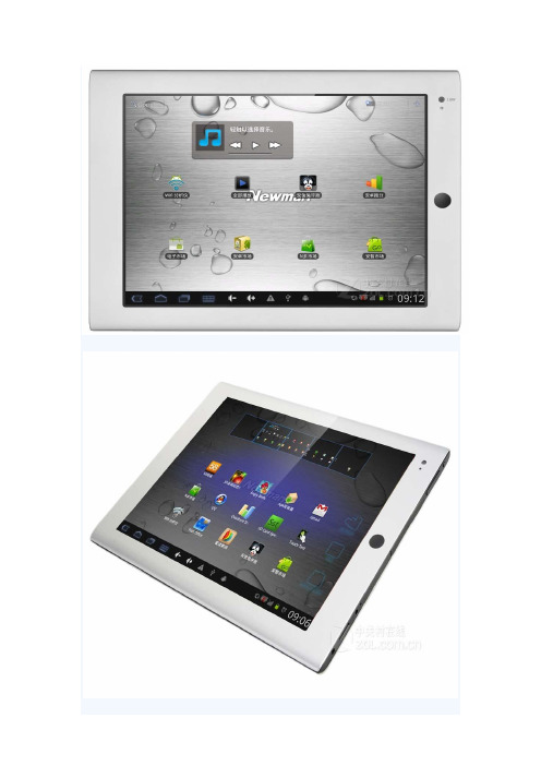
纽曼微薄A1(16GB)详细参数切换到传统表格版基本参数显示屏网络链接音频视频外置接口电源参数功能参数外观参数平板电脑附件保修信息基本参数∙上市时间:2011年12月∙操作系统:Android2.3∙处理器:RK2918 ARM Cortex-A8,1.2GHz∙系统内存:1GB∙存储容量:16GB∙存储介质:Flash 闪盘∙存储卡:支持Micro SD(TF)卡,最大支持32GB显示屏∙屏幕尺寸:9.7英寸∙屏幕分辨率:1024x768∙屏幕描述:电容式触摸屏,多点式触摸屏∙指取设备:触摸屏∙设备描述:IPS屏幕,十点式触摸屏,4:3网络链接∙WiFi功能:支持802.11b/g/n无线协议∙网络模式:移动3G(TD-SCDMA),电信3G(CDMA2000),联通3G(WCDMA)音频视频∙声音系统:内置音效芯片∙音频格式:支持MP3,WMA,APE,FLAC,AAC,OGG,WAV格式∙视频格式:支持RMVB,RM,AVI,MP4,MKV,FLV格式,支持1080P视频外置接口∙数据接口:USB-HOST∙音频接口:3.5mm耳机接口∙视频接口:HDMI接口∙其他接口:电源接口,存储卡接口电源参数∙电池类型:锂电池,8000毫安∙续航时间:10小时左右,具体时间视使用环境而定功能参数∙摄像头:双摄像头(前置:200万像素,后置:200万像素)∙图片浏览:支持JPG,JPEG,BMP,GIF,PNG格式∙内置感应:智能重力感应∙其他功能:支持Flash11外观参数∙产品尺寸:246×186.5×9.6mm ∙机壳材质:铝镁合金材质∙机壳颜色:灰色,黑色,银白色平板电脑附件∙包装清单:平板电脑主机 x1 适配器 x1USB线 x1OTG连接线 x1保修卡 x1说明书 x1保修信息∙保修政策:全国联保,享受三包服务∙质保时间:1年∙质保备注:1年保修,人为损坏不参保∙客服电话:400-810-1989∙电话备注:9:00-18:00∙详细内容:您在购买本产品之日起7日内(含),若产品主机经纽曼红色服务快车中心检测出由于本机元器件所引发之故障,您可以选择退货、更换或维修。
ADP3156资料
SD
Q
VT2
CT
CMPT
ADP3156
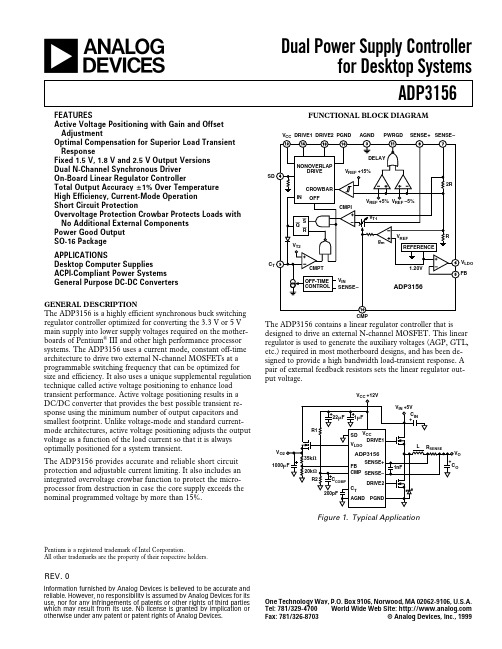
The ADP3156 is a highly efficient synchronous buck switching regulator controller optimized for converting the 3.3 V or 5 V main supply into lower supply voltages required on the motherboards of Pentium® III and other high performance processor systems. The ADP3156 uses a current mode, constant off-time architecture to drive two external N-channel MOSFETs at a programmable switching frequency that can be optimized for size and efficiency. It also uses a unique supplemental regulation technique called active voltage positioning to enhance load transient performance. Active voltage positioning results in a DC/DC converter that provides the best possible transient response using the minimum number of output capacitors and smallest footprint. Unlike voltage-mode and standard currentmode architectures, active voltage positioning adjusts the output voltage as a function of the load current so that it is always optimally positioned for a system transient. The ADP3156 provides accurate and reliable short circuit protection and adjustable current limiting. It also includes an integrated overvoltage crowbar function to protect the microprocessor from destruction in case the core supply exceeds the nominal programmed voltage by more than 15%.
艾桑顿153246系列xPole - eRB6 M RCBO商品说明说明书

Eaton 153246Eaton Moeller series xPole - eRB6/M RCBO - residual-current circuit breaker with overcurrent protection. Electronic RCD/MCB, 25A, 30mA, MCB char. curve: C, 1p, RCCB trip char.: AC, 10kA, MEGeneral specificationsEaton Moeller series xPole - eRB6/M RCBO - residual-current circuit breaker with overcurrent protection153246eRBM-25/1/C/003-ME4015081500130216 mm 72 mm 17.5 mm 0.18 kgCE Marked RoHS conformCEProduct NameCatalog Number Model CodeEANProduct Length/Depth Product Height Product Width Product Weight Compliances Certifications25 AIs the panel builder's responsibility. The specifications for the switchgear must be observed.Meets the product standard's requirements.Is the panel builder's responsibility. The specifications for the switchgear must be observed.3Does not apply, since the entire switchgear needs to be evaluated.Meets the product standard's requirements.0 kA50/60 HzIs the panel builder's responsibility.10.03 A40 °C0 W69.5 mm1 mm²eaton-xpole-erb6/m-dimensions.jpgeaton-xpole-erb6-au-rcbo-catalog-ca019052en-en-us.pdf eaton-xpole-erb6-rcbo-catalog-ca019049en-en-us.pdfDA-DC-03_eRBeaton-xpole-combined-mcb-rcd-device-rcbo-packaging-manual-multilingual.pdfIL019095ZUMA120500735.pdfeaton-xpole-erb6/m-wiring-diagram.jpgRated operational current for specified heat dissipation (In) 10.11 Short-circuit rating10.4 Clearances and creepage distances10.12 Electromagnetic compatibilityCurrent limiting class10.2.5 Lifting10.2.3.1 Verification of thermal stability of enclosures Rated short-circuit breaking capacity (EN 60947-2) Frequency rating10.8 Connections for external conductorsNumber of poles (total)Fault current ratingAmbient operating temperature - maxHeat dissipation per pole, current-dependentBuilt-in depthConnectable conductor cross section (solid-core) - min CataloguesCertification reports Installation instructionsWiring diagrams10.9.3 Impulse withstand voltageIs the panel builder's responsibility.Number of polesSingle-poleAmbient operating temperature - min-25 °C10.6 Incorporation of switching devices and componentsDoes not apply, since the entire switchgear needs to be evaluated.10.5 Protection against electric shockDoes not apply, since the entire switchgear needs to be evaluated.Equipment heat dissipation, current-dependent6.5 W10.13 Mechanical functionThe device meets the requirements, provided the information in the instruction leaflet (IL) is observed.10.2.6 Mechanical impactDoes not apply, since the entire switchgear needs to be evaluated.10.9.4 Testing of enclosures made of insulating materialIs the panel builder's responsibility.Static heat dissipation, non-current-dependent0 WApplicationSwitchgear for residential and commercial applications10.3 Degree of protection of assembliesDoes not apply, since the entire switchgear needs to be evaluated.Voltage typeACNumber of poles (protected)1Leakage current typeACRated short-circuit breaking capacity (EN 61009-1)10 kAOperating ambient temperature - min-25 °CHeat dissipation capacity0 WRelease characteristicCWidth in number of modular spacings1Power loss6.5 W10.2.3.2 Verification of resistance of insulating materials to normal heatMeets the product standard's requirements.10.2.3.3 Resist. of insul. mat. to abnormal heat/fire by internal elect. effectsMeets the product standard's requirements.Rated short-circuit breaking capacity (EN 61009)10 kAOperating ambient temperature - max40 °CVoltage rating240 V - 240 V10.9.2 Power-frequency electric strengthIs the panel builder's responsibility.Connectable conductor cross section (solid-core) - max25 mm²Degree of protectionIP20Overvoltage categoryIIIPollution degree210.7 Internal electrical circuits and connectionsIs the panel builder's responsibility.Connectable conductor cross section (multi-wired) - min1 mm²Rated impulse withstand voltage (Uimp)4 kV10.10 Temperature riseThe panel builder is responsible for the temperature rise calculation. Eaton will provide heat dissipation data for the devices.Basic functionCombined RCD/MCB devicesRated current25 AConnectable conductor cross section (multi-wired) - max 25 mm²TypeRCBO10.2.2 Corrosion resistanceMeets the product standard's requirements.Surge current capacity0.25 kA10.2.4 Resistance to ultra-violet (UV) radiationMeets the product standard's requirements.10.2.7 InscriptionsMeets the product standard's requirements.Rated short-circuit breaking capacity (IEC 60947-2)0 kADisconnection characteristicUndelayedProduct applicationSwitchgear for residential and commercial applicationsRated operational voltage (Ue) - max240 VRated insulation voltage (Ui)500 VEaton Corporation plc Eaton House30 Pembroke Road Dublin 4, Ireland © 2023 Eaton. All rights reserved. Eaton is a registered trademark.All other trademarks areproperty of their respectiveowners./socialmedia。
ACI(美国混凝土协会)标准目录最新

170 ACI 332.1R 171 ACI 546.3R 172 ACI SP-238
173 ACI ITG-4.2R 2006.10.01 174 ACI 234R 175 ACI 350M 176 ACI 350 177 ACI 349M 178 ACI 345.1R 179 ACI 305.1 180 ACI 350.3 181 ACI 302.2R 182 ACI 325.13R 183 ACI 523.1R 184 ACI 440.1R 185 ACI SP-231 186 ACI SP-225 187 ACI 207.1R
100 ACI ITG-7M 101 ACI 311.6 102 ACI ITG-7 103 ACI 439.4R 104 ACI 408.3R 105 ACI 506.5R 106 ACI ITG-5.2
107 ACI 346M 108 ACI 346
ACI 440.2R ERTA ACI 350.2R 110 ERTA
ACI 530/530.1 2011.01.01
53 54 55 56 57 58 59 60 61 62 63 64 65 66 67 68 69 70 71 72 73 74 75 76 77 78 79
ACI 376 ACI 314R ACI 352.1R ACI 548.4 ACI 533R ACI 548.4M ACI 301 ACI 223R ACI ITG-8R ACI 212.3R ACI 423.8R ACI 503.5R ACI 503.3M ACI 306R ACI 305R ACI 503.3 ACI 548.10M ACI ITG-6R ACI 548.10 ACI 332M ACI 440.2R ERTA ACI 332 ACI 357.2R ACI 117M
全志科技股份有限公司Allwinner A系列SDRAM支持列表说明书
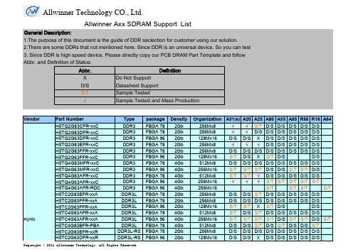
Allwinner Axx SDRAM Support ListGeneral Description:1.The purpose of this document is the guide of DDR seclection for customer using our solution.2.There are some DDRs that not mentioned here. Since DDR is an universal device. So you can test3. Since DDR is high speed device. Please directly copy our PCB DRAM Part Template and followAbbr. and Definition of Status:Abbr.DefinitionX Do Not SupportD/S Datasheet SupportS/T Sample Tested√Sample Tested and Mass ProductionVendor Part Number Type package Density Organization A31(s)A20A23A80A33A83R58R16A64Hynix H5TQ2G83CFR-xxC DDR3FBGA 782Gb256Mx8√√S/T D/S D/S D/S D/S D/SH5TQ2G83DFR-xxC DDR3FBGA 782Gb256Mx8√√D/S D/S D/S D/S D/S D/SH5TQ2G63DFR-xxC DDR3FBGA 962Gb128Mx16D/S D/S X D/S D/S D/S D/S D/SH5TQ2G83EFR-xxC DDR3FBGA 782Gb256Mx8√√√D/S D/S D/S D/S D/SH5TQ2G83FFR-xxC DDR3FBGA 782Gb256Mx8D/S D/S D/S D/S D/S D/S D/S D/SH5TQ2G63FFR-xxC DDR3FBGA 962Gb128Mx16S/T D/S X S/T D/S D/SH5TQ4G83MFR-xxC DDR3FBGA 784Gb512Mx8D/S D/S D/S D/S D/S D/S D/S D/SH5TQ4G63MFR-xxC DDR3FBGA 964Gb256Mx16S/T S/T S/T D/S D/S S/T S/T D/SH5TQ4G83AFR-xxC DDR3FBGA 784Gb512Mx8S/T S/T√D/S D/S D/S D/S D/SH5TQ4G63AFR-xxC DDR3FBGA 964Gb256Mx16√√√S/T S/T S/T S/T S/TH5TQ4G63AFR-RDC DDR3FBGA 964Gb256Mx16S/T S/T S/T S/T H5TC2G83EFR-xxA DDR3L FBGA 782Gb256Mx8D/S D/S S/T D/S D/S D/S D/S D/SH5TC2G83FFR-xxA DDR3L FBGA 782Gb256Mx8D/S D/S D/S D/S D/S D/S D/S D/SH5TC2G63FFR-xxA DDR3L FBGA 962Gb128Mx16S/T S/T X S/T D/S D/SH5TC4G83AFR-xxA DDR3L FBGA 784Gb512Mx8S/T D/S S/T D/S D/S D/S D/S D/SH5TC4G63AFR-xxA DDR3L FBGA 964Gb256Mx16S/T S/T S/T S/T D/S S/T S/T D/S S/T H5TC4G83BFR-PBA DDR3L FBGA 784Gb512Mx8D/S D/S S/T D/S S/T D/S D/S S/TH5TC2G83EFR-xxR DDR3L-RS FBGA 782Gb256Mx8D/S D/S D/S D/S D/S D/S D/S D/SH5TC2G63DFR-xxR DDR3L-RS FBGA 962Gb128Mx16D/S D/S X D/S D/S D/S D/S D/SH5TC2G63FFR-xxR DDR3L-RS FBGA 962Gb128Mx16D/S D/S X D/S D/S D/S D/S D/SH5TC4G83AFR-xxR DDR3L-RS FBGA 784Gb512Mx8D/S D/S D/S D/S D/S D/S D/S D/SH5TC4G63AFR-xxR DDR3L-RS FBGA 964Gb256Mx16D/S D/S D/S D/S D/S D/S D/S D/SH5TC8G63AMR-PBA DDR3L FBGA 968Gb256Mx16x2CS D/S D/S X S/T S/T S/T S/T S/TH5TC8G83AMR-PBA DDR3L FBGA 788Gb512Mx8x2CS D/S D/S X D/S D/S D/S D/S D/SH5TC4G63CFR-PBA DDR3L FBGA 964Gb256Mx16D/S D/S D/S D/S D/S S/T S/T D/S S/T H9TKNNN8JDAPLR-NGN LPDDR28Gb128Mx32x2CS D/S X X D/S X D/S D/S XH9CCNNN8JTALAR-NTD LPDDR3FBGA 1788Gb128Mx32x2CS D/S X X S/T X S/T S/T XH9CCNNNBLTALAR-NTM LPDDR3FBGA 17816Gb256Mx32x2CS S/T S/TH9CKNNN8GTMPLR-NUH LPDDR3POP 1688Gb128Mx32x2CS S/T S/TH9CCNNNBJTMLAR-NUM LPDDR3POP 16816Gb256Mx32x2CSNanya(南亚)NT5CB128M8DN-xx DDR3FBGA 781Gb128Mx8D/S S/T X X X D/S D/S XNT5CB256M8GN-xx DDR3FBGA 782Gb256Mx8S/T S/T S/T D/S S/T D/S D/S S/TNT5CB256M8FN-xx DDR3FBGA 782Gb256Mx8S/T S/T S/T D/S D/S D/S D/S D/SNT5CB128M16HP-xx DDR3FBGA 962Gb128Mx16S/T S/T X S/T D/S D/SNT5CB128M16FP-xx DDR3FBGA 962Gb128Mx16D/S D/S X D/S D/S D/SNT5CB256M16BP-xx DDR3FBGA 964Gb256Mx16S/T S/T S/T S/T S/T D/S D/S S/TNT5CC512M8CN-xx DDR3L FBGA 784Gb512Mx8S/T S/T S/T D/S D/S D/S D/S D/SNT5CC256M16CP-xx DDR3L FBGA 964Gb256Mx16S/T D/S D/S D/S D/S D/S D/S D/SNT5CC256M16CP-DI DDR3L FBGA 964Gb256Mx16S/T S/T S/T S/T S/T S/T NT6CL256T32AQ-H2LPDDR3POP 1688Gb128Mx32x2CS S/T S/TNT6CL128M32AQ-H2LPDDR3POP 1684Gb128Mx32x1CS D/S D/SNT5CC256M16DP-DI DDR3L FBGA 964Gb256Mx16S/T S/T S/T S/T NT5CC128M16IP-DI DDR3L FBGA 962Gb128Mx16NT5CB64M16FP-DH DDR3FBGA 961Gb64Mx16NT6TL256T32AQ-G1LPDDR2POP 1688Gb128Mx32x2CS S/T S/TNT6TL128M32AQ-G0LPDDR2POP 1684Gb128Mx32x1CS S/T S/TNT5CC64M16GP-DI DDR3L FBGA 961Gb64Mx16Elpida EDJ2108BDBG-DJ-F DDR3FBGA 782Gb256Mx8D/S D/S D/S D/S D/S D/S D/S D/SEDJ4216EFBG-GN-F DDR3FBGA 964Gb256Mx16S/T S/T S/T S/T S/T D/S D/S S/TEDJ4208EFBG-GNL-F DDR3L FBGA 784Gb512Mx8S/T S/T D/S D/S D/S D/S D/S D/SEDJ4208EFBG-GN-F DDR3FBGA 784Gb512Mx8S/T S/T D/S D/S D/S D/S D/S D/SEDJ4216EFBG-GNL-F DDR3L FBGA 964Gb256Mx16S/T S/T S/T D/S S/T D/S D/S S/T S/T J2108DEBG-DJ-F DDR3FBGA 782Gb256Mx8D/S D/S D/S D/S D/S D/S D/S D/SAllwinner Technology CO., Ltd.ElpidaEDB8132B3MC-8D-F LPDDR28Gb128Mx32x2CS S/T X X S/T X D/S D/S XEDB8132B2MA-8D-F LPDDR28Gb128Mx32x2CS D/S X X S/T X D/S D/S XEDFA232A1MA-GD-F LPDDR316Gb256Mx32x2CS D/S X X D/S X D/S D/S XMicron MT41K256M8DA-125DDR3L FBGA 782Gb256Mx8D/S D/S S/T D/S D/S D/S D/S D/SMT41K128M16JT-125DDR3L FBGA 962Gb128Mx16S/T D/S X X X D/S D/S XMT41J128M16JT-107DDR3FBGA 962Gb128Mx16S/T S/T X X X D/S D/S XMT41K256M16HA-125DDR3L FBGA 964Gb256Mx16S/T D/S S/T S/T S/T D/S D/S S/T S/T MT41K512M8RH-125DDR3L FBGA 784Gb512Mx8D/S D/S S/T D/S D/S D/S D/S D/SMT41J256M8HX-15DDR3FBGA 782Gb256Mx8D/S D/S S/T D/S S/T D/S D/S S/TSAMSUNG K4B4G1646B-HCK0DDR3FBGA 964Gb256Mx16S/T S/T S/T D/S D/S S/T S/T D/SK4B2G1646E-BCK0DDR3FBGA 962Gb128Mx16S/T D/S X D/S D/S D/SK4B2G0846D-HCK0DDR3FBGA 782Gb256Mx8D/S D/S D/S D/S D/S D/S D/S D/SK4B2G1646Q-BCK0DDR3FBGA 962Gb128Mx16S/T D/S X D/S S/T D/S D/S S/TK4B4G1646Q-HYK0DDR3L FBGA 964Gb256Mx16S/T S/T S/T S/T S/T S/T S/T S/T S/T K4B8G1646Q-MYK0DDR3L FBGA968Gb256Mx16x2CS D/S D/S X D/S D/S S/T S/T D/SK4B4G1646D-BCK0DDR3FBGA964Gb256Mx16S/T K4E8E304ED-EGCF LPDDR3FBGA 1788Gb128Mx32x2CS D/S X X S/T X S/T S/T XK4E8E304ED-EGCE LPDDR3FBGA 1788Gb128Mx32x2CS D/S X X D/S X S/T S/T XK4E8E304ED-EGCC LPDDR3FBGA 1788Gb128Mx32x2CS D/S X X S/T X S/T S/T XK4E4E324ED-EGCF LPDDR3FBGA 1784Gb128Mx32x1CS S/T X X D/S X D/S D/S XK4P8G304EG-AGC2LPDDR2POP 1688Gb128Mx32x2CS S/T X X D/S X D/S D/S XK4E8E304EE-EGCE LPDDR3FBGA 1788Gb128Mx32x2CS D/S X X S/T X S/T S/T X S/T K4E6E304EE-EGCE LPDDR3FBGA 17816Gb256Mx32x2CS S/T S/TK4P8G304EQ-AGC2LPDDR2POP 1688Gb128Mx32x2CS S/T S/T S/T K4E8E304EE-AGCE LPDDR3POP 1688Gb128Mx32x2CS S/T S/TK4E4E164EB-EGCE LPDDR3FBGA 1784Gb128Mx32x1CS S/T S/TKingston(金士顿)D2516EC4BXGGB DDR3FBGA 964Gb256Mx16S/T S/T S/T D/S D/S S/T S/T D/SPSC/Mira (力晶)P3P4GF3BLF-GGN DDR3FBGA 784Gb512Mx8D/S S/T S/T D/S D/S D/S D/S D/S P3P4GF4BLF-GGN DDR3FBGA 964Gb256Mx16S/T S/T S/T D/S S/T D/S D/S S/T P3P4GF4BLF-GDJ DDR3FBGA 964Gb256Mx16D/S S/T S/T D/S D/S D/S D/S D/S P3P2GF3BLF-AGGN DDR3FBGA 782Gb256Mx8S/TAllwinner Technology CO., Ltd.Etron (钰创)EM6GE16EW5B-15H DDR3FBGA 964Gb 256Mx16S/T S/T S/T D/S D/S D/S D/S D/S EM6GD08EWUA-15H DDR3FBGA 782Gb 256Mx8D/S D/S S/T D/S S/T D/S D/S S/T EM6GD08EWUA-12H DDR3FBGA 782Gb 256Mx8D/SD/S S/T D/S D/S D/S D/S D/SEM6GD16EWXC-12HDDR3FBGA 962Gb 128Mx16EM6GE16EWXC-12HDDR3FBGA 964Gb 256Mx16S/T D/S D/S EM6GD08EWUC-12H DDR3FBGA 782Gb 256Mx8S/T D/S D/S EM6GE08EW8C-12H DDR3FBGA 784Gb 512Mx8S/TD/S D/SEM6GE16EWXD-12H DDR3FBGA 964Gb 256Mx16SCSemicon (华芯)HXB15H2G800BF-15H DDR3FBGA 782Gb 256Mx8S/T S/T S/T D/S D/S D/S HXB15H2G160BF-15H DDR3FBGA 962Gb 128Mx16D/S S/T X X X X HXB15H4G160BF-15HDDR3FBGA 964Gb 256Mx16S/T S/T S/T D/S S/T S/T HXB15H4G800BF-15H DDR3FBGA 784Gb 512Mx8D/S D/S S/T D/S D/S D/S HXB15H4G800AF-15HDDR3FBGA 784Gb 512Mx8D/S D/S S/T D/S D/SD/S HXB13H4G160BF(L)-13K DDR3L FBGA 964Gb 256Mx16D/S D/SD/S D/S D/S S/T S/T D/SHXB15H2G800BF-13K DDR3FBGA 782Gb 256Mx8S/THXB15H2G160BF-13KDDR3FBGA 962Gb 128Mx16PI (补丁)PMF511808DBR-KADN DDR3FBGA 782Gb 256Mx8D/S D/S S/T D/S D/S D/S PMF512816BBR-KADN DDR3FBGA 964Gb 256Mx16S/T S/T S/T D/S D/S S/T S/T D/S PMF511808BBRDDR3FBGA 782Gb 256Mx8D/S D/S S/T D/S D/S D/S eorex (森富)EM47DM0888SBA-150DDR3FBGA 781Gb 128Mx8D/S D/S X X X XEM47EM0888SBA-150DDR3FBGA 782Gb 256Mx8D/S D/S S/T D/S D/S D/S EM47CM1688SBB-150DDR3FBGA 961Gb 64Mx16D/S D/S X X X X EM47EM1688SBA-150DDR3FBGA 964Gb 256Mx16D/S S/T S/T D/S D/S D/S EM47EM3288SBA-150DDR38Gb 256Mx32S/T D/S X X XXGT (创芯)GT8UB128M16HP DDR3FBGA 962Gb 128Mx16S/T S/T X D/S D/S D/S GT8UB128M16BP DDR3FBGA 962Gb 128Mx16D/S S/T X D/S D/S D/S GT8UB256M16BP DDR3FBGA 964Gb 256Mx16S/T S/T S/T D/S D/S S/T S/T D/S GT8UB256M8EN-BG DDR3FBGA 782Gb 256Mx8D/S D/S S/T D/S D/S D/S GT8UB512M8EN-BGDDR3FBGA 784Gb512Mx8D/SD/S S/T D/S D/S D/SEG EG1L256M88BA12LH DDR3FBGA 782Gb 256Mx8D/S D/S S/T D/S D/S D/SAllwinner Technology CO., Ltd. EGElixir N2CB2G80GN DDR3FBGA 782Gb256Mx8D/S S/T S/T D/S D/S D/S N2CB4G16CP-DI DDR3FBGA 964Gb256Mx16D/S D/S S/T D/S D/S D/S华聆 xeme H2A402G1666ADBC DDR3FBGA 962Gb128Mx16H2A402G0866CD3C DDR3FBGA 782Gb256Mx8H2A404G0866ED9C DDR3FBGA 784Gb512Mx8H2C402G1666ADBC DDR3FBGA 962Gb128Mx16H2C402G0866CD3C DDR3FBGA 782Gb256Mx8H2C402G0866BD3C DDR3FBGA 782Gb256Mx8H2C404G0866ADEC DDR3FBGA 784Gb512Mx8H2C404G1666ADFC DDR3FBGA 964Gb256Mx16S/T S/T S/T S/T H2C404G0866CD8C DDR3FBGA 784Gb512Mx8H2C402G1666BDBC DDR3FBGA 962Gb128Mx16X X H2A402G0866CD3C DDR3FBGA 782Gb256Mx8XGCAI GDB41A32ED7-D1S LPDDR2POP 1684Gb128Mx32x1CS GDB42A32ED7-D1S(25nm)LPDDR2POP 1688Gb128Mx32x2CS GDB42A32ED7-D1S(30nm)LPDDR2POP 1688Gb128Mx32x2CS。
ABA-31563-TR2G中文资料
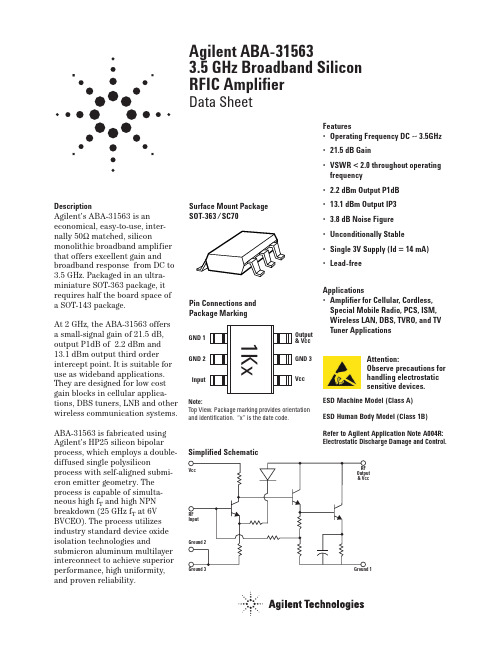
Surface Mount Package SOT-363 /SC70
Pin Connections and Package Marking
GND 1 GND 2 Input
1Kx
Output & Vcc
GND 3
Vcc
Note: Top View. Package marking provides orientation and identification. “x” is the date code.
f = 0.1 ~ 2.5 GHz f = 0.1 ~ 3.5 GHz
Noise Figure
Output Power at 1dB Gain Compression
Output Third Order Intercept Point
Input VSWR
Output VSWR
Device Current
Tc = +25°C, Zo = 50Ω, Vcc = 3V unless stated otherwise.
23
23
22
22
21
21
GAIN (dB)
GAIN (dB)
20
20
19
3.5V
3V
18
2.7V
17 0 0.5 1 1.5 2 2.5 3 3.5 4
FREQUENCY (GHz)
Figure 2. Gain vs. Frequency and Voltage.
P1dB (dBm)
6
4
2
0
3.5V
-2
3V
2.7V
-4 0 0.5 1 1.5 2 2.5 3 3.5 4 FREQUENCY (GHz)
诺亚舟 NH6000A 电子词典 说明书

前 言承蒙惠购本公司产品,本公司将竭诚为您提供优质完善的产品和服务。
本辞典是一款集辞典、记事、计算、时间、学习、娱乐、网络下载和百科资料浏览等诸多功能于一体的高科技产品。
它不仅涵盖了普通电子辞典的全部功能,更将特有的语音技术和海量的存储优势融入整体之中。
相信它会使您的学习更高效、工作更轻松、生活更自由。
为保证您能充分了解和使用本产品的功能,请您务必仔细阅读说明书,阅读后请妥善保存,以备日后参考之用。
本公司致力于不断提升产品性能,因此保留对本书中所阐述的功能和人机界面进行改进而不预先通知的权利。
科技创造好生活!目 录一. 机身简介 (5)二. 开机画面 (6)三. 基本使用说明 (6)1.使用注意事项 (6)2.按键功能说明 (7)3.屏幕标识说明 (9)4.输入法简介 (10)5.电源使用方法 (11)6.系统复位 (12)四. 目录功能 (12)五. 辞典功能 (13)1.英汉词典功能 (13)2.汉英词典功能 (17)3.汉语字典功能 (18)4.成语词典功能 (19)5.专业词典功能 (20)6.英英词典功能 (22)六. 学习功能 (22)1.学习园地 (22)2.辞典附录 (28)3.语法大全 (28)4.分类会话 (28)5.分类词库 (28)6.进阶必备 (29)17.构词法 (29)8.英语沙龙 (29)七. 娱乐功能 (29)1.娱乐套餐 (29)2.休闲空间 (29)3.IQ总动员 (29)4.谜语天地 (30)5.心理测试 (30)6.影视频道 (30)7.音乐时空 (30)8.体育大观 (31)八. 游戏功能 (31)九. 记事功能 (31)1.名片功能 (31)2.备忘功能 (34)3.个人理财功能 (36)4.课程表 (36)5.机主信息 (36)十. 计算功能 (36)1.计算器 (36)2.科学计算 (38)3.统计计算 (40)4.进制换算 (41)5.单位换算 (41)6.汇率换算 (42)7.增值税 (44)28.贷款按揭 (44)9.所得税 (45)十一. 时间功能 (46)1.时间日期 (46)2.时间校正 (46)3.时间方式 (47)4.闹铃设置 (47)5.行程提醒 (47)6.月历 (47)7.世界时区 (48)8.秒表 (48)9.倒数计日 (48)十二. 资料功能 (48)1.生活手册 (48)2.理科公式 (48)3.文科常识 (48)4.文学鉴赏 (49)5.法律法规 (49)6.环球旅游 (49)7.人生预测 (49)8.健康保健 (49)9.青青校园 (50)十三. 系统 (51)1.开机设置 (51)2.发音模式 (51)3.系统设置 (52)34.资源管理 (54)5.产品信息 (55)十四. 下载功能 (55)1.PC机系统的基本要求 (55)2.软件安装 (55)3.下载概述 (56)十五. 产品规格 (58)十六. 售后服务 (59)附录a: 五笔字型键盘字根总图 (60)附录b: 简易故障排除方法 (61)45一、机身简介6二、开机画面打开辞典翻盖,按键盘的开关按钮即出现开机画面并伴有音乐声:此为其中一画面,画面和音乐可选择三、基本使用说明1、使用注意事项● 不要擅自对本机进行拆卸。
FL75L05 A;中文规格书,Datasheet资料
FL75R10A Filter Module75Vdc Input Maximum, 10A MaximumFEATURESROHS CompliantSmall size: 25.4mm x 25.4mm x 10.2mm(1.0” x 1.0” x 0.4”)Industry standard footprint and pin-outOptimized for use with high frequency Array board mounted DC/DC convertersPrinted-circuit board mountableISO 9001, TL 9000, ISO 14001, QS 9000,OHSAS 18001 certified manufacturing facilityUL/cUL 60950 (US & Canada) Recognized,VDE 0805 (IEC60950) LicensedDelphi Series Filter Module -FL75L05 A75Vdc input, 5A current RatingThe Delphi series FL75L05 A filter module is the latest offering from aworld leader in power systems technology and manufacturing – DeltaElectronics, Inc. This filter module is designed to reduce the conductedcommon-mode and differential-mode noise on input or output lines ofhigh-frequency switching power supplies and has a maximum currentrating of 5A. It has the industry standard footprint and pin-out. Withcreative design technology and optimization of component placement,Delphi FL75L05 A filter module possesses outstanding electrical andthermal performance, as well as extremely high reliability under highlystressful operating conditions.APPLICATIONSCommon-mode and differential-modefiltering of power supply dc input andoutput lineComputer applicationCommunications equipmentSPECIFICATIONSGENERAL SPECIFICATIONSOUTPUT SPECIFICATIONSInput voltage, continuous Typical 0~75V Output current Ta=75°C, no airflow 5A Input voltage, transient Typical 100V Output current Ta=85°C, no airflow 4A Operation case temperature Typical-40¢ ~ 120¢ Common-modeInsertionLoss50£circuit, 500 kHz (Typ)43dB Storage temperature Typical -55¢ ~ 125¢ Differential-modeInsertionLoss50£circuit, 500 kHz (Typ)45dB Size (1.0”. x 1.0”x 0.4”). 25.4 x 25.4 x 10.2 mmELECTRICAL CHARACTERISTICS CURVESFigure 1:Typical common-mode insertion loss in a 50£circuit Figure 2: Typical differential-mode insertion loss in a 50£circuitInternal SchematicsFigure 3: Internal schematicsTHERMAL CONSIDERATIONSusually the dominant mode of heat transfer.tunnel.Thermal Testing Setupthe power modules are mounted.The following figure shows the wind tunnelcharacterization setup. The filter module is mounted onNote: Wind Tunnel Test Setup Figure Dimensions are in millimeters and (Inches)Figure 4: Wind tunnel test setup figure dimensions are inmillimeters and (inches).The allowed maximum hot spot temperature is defined at 120FL75L05 (Standard) Output Current vs. Ambient Temperature and Air Velocity5055606570758085Ambient Temperature (¢)Figure 6: Output Current vs. Ambient Temperature and AirVelocity @ Vin = 48V (Either Orientation)APPLICATIONNote: C2 through C5 can be 0.01£g F to o.1£g F. Select the voltage rating to meet input-to-output isolation requirements. C1 should be the recommended value indicated in the power module data sheet.Figure 7. Recommended schematic when used as the input filter to a high-frequency dc-to-dc converterNote: Vdc input(+) and Vdc input(-) planes should overlay each other, as should the Vi(+) and Vi(-) planes, as should the Vout(+) and Vout(-) planes. Avoid routing signals or planes under the power module or the filter module. Ensure all connections are low impedance.Figure 8. Recommended layout when used as the input filter to a high-frequency dc-to-dc converterAPPLICATION (Continued)Note: : C2 through C5 and C6 through C9 can be 0.01£g F to o.1£g F. Select the voltage rating to meet input-to-output isolation requirements. C1 should be the recommended value indicated in the power module datasheet.Figure 9. Recommended schematic of filter module with two power modulesFigure 10 shows the experimental result obtained by using this filter module, together with the recommended external components shown in Figures 5 and 6. The Q48SR3R335NR module is one of the Delphi series quarter brick 3.3V, 35A DCDC converters. Measured noise is greatly dependent on layout, grounding, cable orientation, and load characteristics and the variation is possible from various application conditions.Figure 10.Q48SR3R335NR A conducted noise with FL75L05 input filterMECHANICAL DRAWINGTop View Side View Bottom ViewDimensions are in millimeter and (inches).Tolerances : x.xx 0.5 mm (0.02 in), x.xxx 0.25 mm (0.010 in)RECOMMENDED HOLE PATTERNDimensions are in millimeter and (inches).Tolerances : x.xx 0.5 mm (0.02 in), x.xxx 0.25 mm (0.010 in)PART NUMBERING SYSTEMFL 75L05 AProduct Family Input Voltage Product Series Output Current Space Option CodeFL- EMI Filter 75- 0 ~ 75V L – Industry standard05 - 5A A - Standard FunctionsMODEL LISTModule Name Input Voltage (max.) Current Rating (max.)Size (metric) Size (English unit) FL75L05 A 75V 5A 25.4 x 25.4 x 10.2 mm 1.0 in. x 1.0 in. x 0.4 in.FL75L10 A 75V 10A 50.8 x 27.9 x 12.5 mm 2.0 in. x 1.1 in. x 0.5 in.FL75L20 A 75V 20A 50.8 x 40.6 x 12.7 mm 2.0 in. x 1.6 in. x 0.5 in. CONTACT: /dcdcUSA:Telephone:East Coast: (888) 335 8201 West Coast: (888) 335 8208 Fax: (978) 656 3964Email: DCDC@ Europe:Telephone: +41 31 998 53 11Fax: +41 31 998 53 53Email: DCDC@delta-es.twAsia & the rest of world:Telephone: +886 3 4526107 ext 6220Fax: +886 3 4513485Email: DCDC@WARRANTYDelta offers a two (2) year limited warranty. Complete warranty information is listed on our web site or is available upon request from Delta. Information furnished by Delta is believed to be accurate and reliable. However, no responsibility is assumed by Delta for its use, nor for any infringements of patents or other rights of third parties, which may result from its use. No license is granted by implication or otherwise under any patent or patent rights of Delta. Delta reserves the right to revise these specifications at any time, without notice.分销商库存信息: DELTA-PRODUCT-GROUPS FL75L05 A。
MOXA NPort W2150A W2250A产品说明书
NPort W2150A/W2250A Series1and2-port serial-to-WiFi(802.11a/b/g/n)device servers with wireless clientFeatures and Benefits•Links serial and Ethernet devices to an IEEE802.11a/b/g/n network•Web-based configuration using built-in Ethernet or WLAN•Enhanced surge protection for serial,LAN,and power•Remote configuration with HTTPS,SSH•Secure data access with WEP,WPA,WPA2•Fast roaming for quick automatic switching between access points•Offline port buffering and serial data log•Dual power inputs(1screw-type power jack,1terminal block)CertificationsIntroductionThe NPort®W2150A and W2250A are the ideal choice for connecting your serial and Ethernet devices,such as PLCs,meters,and sensors,to a wireless LAN.Your communications software will be able to access the serial devices from anywhere over a wireless LAN.Moreover,the wireless device servers require fewer cables and are ideal for applications that involve difficult wiring situations.In Infrastructure Mode or Ad-Hoc Mode,the NPort®W2150A and NPort®W2250A can connect to Wi-Fi networks at offices and factories to allow users to move,or roam,between several APs (access points),and offer an excellent solution for devices that are frequently moved from place to place.SpecificationsEthernet Interface10/100BaseT(X)Ports(RJ45connector)1Magnetic Isolation Protection 1.5kV(built-in)Standards IEEE802.3for10BaseTIEEE802.3u for100BaseT(X)Ethernet Software FeaturesConfiguration Options Web Console(HTTP/HTTPS),Windows UtilityManagement DHCP Option82,HTTP,IPv4,SMTP,SNMPv1/v2c/v3,Syslog,Telnet,Web Console Windows Real COM Drivers Windows95/98/ME/NT/2000,Windows XP/2003/Vista/2008/7/8/8.1/10(x86/x64),Windows2008R2/2012/2012R2(x64),Windows Embedded CE5.0/6.0,Windows XPEmbeddedLinux Real TTY Drivers Kernel version:2.4.x,2.6.x,3.x,4.xFixed TTY Drivers SCO UNIX,SCO OpenServer,UnixWare7,QNX4.25,QNX6,Solaris10,FreeBSD,AIX5.x,HP-UX11i,Mac OS XAndroid API Android3.1.x and laterMIB Device Settings MIB,RFC1213,RFC1317Security HTTPS/SSL,Local Account Accessibility,TACACS+,SSHTime Management NTP Client,SNTP ClientWLAN InterfaceWLAN Standards802.11a/b/g/nReceiver Sensitivity for802.11a-91dBm@6Mbps-74dBm@54MbpsReceiver Sensitivity for802.11b-92dBm@1Mbps-84dBm@11MbpsReceiver Sensitivity for802.11g-91dBm@6Mbps-73dBm@54MbpsReceiver Sensitivity for802.11n(2.4GHz)-89dBm@6.5Mbps(20MHz)-71dBm@72.2Mbps(20MHz)Receiver Sensitivity for802.11n(5GHz)-89dBm@6.5Mbps(20MHz)-71dBm@72.2Mbps(20MHz)-85dBm@13.5Mbps(40MHz)-67dBm@150Mbps(40MHz)Modulation Type DSSSOFDMTransmission Distance Up to100meters(in open areas)Transmission Rate802.11a/g:54Mbps802.11b:11Mbps802.11n:6.5to150MbpsTransmitter Power for802.11b16±1.5dBm@1Mbps16±1.5dBm@11MbpsTransmitter Power for802.11g16±1.5dBm@6Mbps14±1.5dBm@54MbpsTransmitter Power for802.11a15±1.5dBm@6Mbps14±1.5dBm@54MbpsTransmitter Power for802.11n(2.4GHz)16dBm@1.5Mbps(6.5MHz)12dBm@1.5Mbps(72.2MHz)Transmitter Power for802.11n(5GHz)15dBm@1.5Mbps(6.5MHz)12dBm@1.5Mbps(150MHz)Wireless Security WEP encryption(64-bit and128-bit)WPA/WPA2-Enterprise(IEEE802.1X/RADIUS,TKIP,AES)WPA/WPA2-PersonalWLAN Modes Ad-hoc Mode,Infrastructure modeSerial InterfaceConnector DB9maleNo.of Ports NPort W2150A/W2150A-T:1NPort W2250A/W2250A-T:2Serial Standards RS-232,RS-422,RS-485Operation Modes Real COM mode,TCP Server mode,TCP Client mode,UDP mode,RFC2217mode,PairConnection mode,Ethernet Modem mode,DisabledBaudrate50bps to921.6kbpsData Bits5,6,7,8Stop Bits1,1.5,2Parity None,Even,Odd,Space,MarkFlow Control None,RTS/CTS,XON/XOFFRS-485Data Direction Control ADDC®(automatic data direction control)Pull High/Low Resistor for RS-4851kilo-ohm,150kilo-ohmsTerminator for RS-485120ohmsSurge1kVPhysical CharacteristicsHousing MetalInstallation Desktop,DIN-rail mounting(with optional kit),Wall mountingDimensions(with ears,without antenna)77x111x26mm(3.03x4.37x1.02in)Dimensions(without ears or antenna)100x111x26mm(3.94x4.37x1.02in)Weight NPort W2150A/W2150A-T:547g(1.21lb)NPort W2250A/W2250A-T:557g(1.23lb)Antenna Length109.79mm(4.32in)Environmental LimitsOperating Temperature Standard Models:0to55°C(32to131°F)Wide Temp.Models:-40to75°C(-40to167°F)Storage Temperature(package included)-40to75°C(-40to167°F)Ambient Relative Humidity5to95%(non-condensing)Power ParametersInput Current NPort W2150A/W2150A-T:179mA@12VDCNPort W2250A/W2250A-T:200mA@12VDCInput Voltage12to48VDCStandards and CertificationsEMC EN55032/24EMI CISPR32,FCC Part15B Class AEMS IEC61000-4-2ESD:Contact:4kV;Air:8kVIEC61000-4-3RS:80MHz to1GHz:3V/mIEC61000-4-4EFT:Power:2kV;Signal:2kVIEC61000-4-5Surge:Power:2kV;Signal:1kVIEC61000-4-6CS:150kHz to80MHz:3V/m;Signal:3V/mIEC61000-4-8PFMFIEC61000-4-11DIPsRadio Frequency CE(ETSI EN301893,ETSI EN300328,ETSI EN301489-17,ETSI EN301489-1),ARIBRCR STD-33,ARIB STD-66ReliabilityAlert Tools RTC(real-time clock)Automatic Reboot Trigger Built-in WDTMTBFTime NPort W2150A/W2150A-T:383,187hrsNPort W2250A/W2250A-T:363,327hrsStandardsTelcordia (Bellcore)Standard TR/SR WarrantyWarranty Period5years Details See /warrantyPackage ContentsDevice1x NPort W2150A/W2250A Series device server Power Supply1x power adapter,suitable for your region (standard temp.models only)Antenna1x 2.4/5GHz antenna Documentation 1x quick installation guide1x warranty card DimensionsOrdering InformationModel NameNo.of serial ports Serial Standards Baudrate Operating Temp.Input Current Input Voltage NPort W2150A 1RS-232/422/48550bps to 921.6kbps0to 55°C 179mA @12VDC 12-48VDC NPort W2250A 2RS-232/422/48550bps to 921.6kbps0to 55°C 200mA @12VDC 12-48VDC NPort W2150A-T 1RS-232/422/48550bps to 921.6kbps-40to 75°C 179mA @12VDC 12-48VDC NPort W2250A-T 2RS-232/422/48550bps to 921.6kbps -40to 75°C 200mA @12VDC 12-48VDCAccessories(sold separately)CablesCBL-F9M9-150DB9female to DB9male serial cable,1.5mCBL-F9M9-20DB9female to DB9male serial cable,20cmConnectorsADP-RJ458P-DB9F DB9female to RJ45connectorMini DB9F-to-TB DB9female to terminal block connectorDIN-Rail Mounting KitsDK35A DIN-rail mounting kit,35mmPower CordsCBL-PJ21NOPEN-BK-30Locking barrel plug to bare-wire cablePower AdaptersPWR-12050-WPAU-S1Locking barrel plug,12VDC,0.5A,100-240VAC,Australia(AU)plug,0to40°C operating temperature PWR-12050-WPCN-S1Locking barrel plug,12VDC,0.5A,100-240VAC,China(CN)plug,0to40°C operating temperature PWR-12050-WPEU-S1Locking barrel plug,12VDC,0.5A,100-240VAC,Continental Europe(EU)plug,0to40°C operatingtemperaturePWR-12050-WPUK-S1Locking barrel plug,12VDC,0.5A,100-240VAC,United Kingdom(UK)plug,0to40°C operatingtemperaturePWR-12050-WPUSJP-S1Locking barrel plug,12VDC,0.5A,100-240VAC,United States/Japan(US/JP)plug,0to40°Coperating temperaturePWR-12150-AU-SA-T Locking barrel plug,12VDC,1.5A,100-240VAC,Australia(AU)plug,-40to75°C operatingtemperatureApplicable Models:NPort W2150A-TNPort W2250A-TPWR-12150-CN-SA-T Locking barrel plug,12VDC,1.5A,100-240VAC,China(CN)plug,-40to75°C operating temperatureApplicable Models:NPort W2150A-TNPort W2250A-TPWR-12150-EU-SA-T Locking barrel plug,12VDC,1.5A,100-240VAC,Continental Europe(EU)plug,-40to75°C operatingtemperatureApplicable Models:NPort W2150A-TNPort W2250A-TPWR-12150-UK-SA-T Locking barrel plug,12VDC,1.5A,100-240VAC,United Kingdom(UK)plug,-40to75°C operatingtemperatureApplicable Models:NPort W2150A-TNPort W2250A-TPWR-12150-USJP-SA-T Locking barrel plug,12VDC1.5A,100-240VAC,United States/Japan(US/JP)plug,-40to75°Coperating temperatureApplicable Models:NPort W2150A-TNPort W2250A-TAntennasANT-WDB-ARM-02 2.4/5GHz,omni-directional rubber duck antenna,2dBi,RP-SMA(male)©Moxa Inc.All rights reserved.Updated Apr17,2019.This document and any portion thereof may not be reproduced or used in any manner whatsoever without the express written permission of Moxa Inc.Product specifications subject to change without notice.Visit our website for the most up-to-date product information.。
艾瓦特芯片规格书

艾瓦特芯片规格书如下:一、产品概述艾瓦特芯片是专为高性能计算和人工智能应用设计的高端芯片。
它采用最先进的7纳米工艺制造,具有高性能、低功耗和低热量排放的特点。
艾瓦特芯片支持并行计算,可以高效处理大规模数据和算法,是提高计算性能的关键组件。
二、技术规格1. 工艺技术:7纳米工艺制造2. 核心数量:双核心3. 内存带宽:高达51.2GB/s4. 计算能力:强大的计算能力,适用于高性能计算和人工智能应用5. 能耗:低功耗设计,适合节能环保6. 热量排放:先进的散热技术,确保芯片在高负荷运行时稳定可靠7. 工作温度:工作温度范围宽广,适应各种环境和使用场景三、性能特点1. 高性能:艾瓦特芯片采用并行计算架构,可高效处理大规模数据和算法,提高计算性能。
2. 高效能比:在相同的计算任务下,艾瓦特芯片的性能比传统处理器高得多。
3. 节能环保:低功耗设计和先进的散热技术,确保芯片在长时间运行和高温环境下稳定可靠。
4. 兼容性:艾瓦特芯片兼容现有的软件和硬件系统,方便用户使用。
四、应用领域艾瓦特芯片适用于各种高性能计算和人工智能应用,如大数据分析、云计算、机器学习和深度学习等。
它能够为各种应用提供强大的计算能力,提高工作效率和性能比。
五、生产与品质艾瓦特芯片采用最先进的生产工艺,确保产品的高品质和高稳定性。
我们的质量控制流程严格遵循行业标准,从原料到成品进行全面检测,确保产品的性能和质量达到最高水平。
六、服务与支持我们提供全面的售后服务和技术支持,包括产品咨询、故障排除、解决方案提供等。
我们承诺在第一时间解决客户的问题,确保客户的利益和满意度。
以上就是艾瓦特芯片的规格书,我们致力于为客户提供高性能、稳定可靠的产品,帮助客户实现更高的计算性能和效率。
01-水性及高固体份汽车修补漆 _湛新树脂 2016 03

固含%
羟值%
产品描述
42
4.1
厚膜无针 孔性,高 光泽
42
4.2
42
4.1
44
3.0
快干,异 氰酸酯用 量少
43
4.4
流变性,达 150um无针孔, 哑光,耐水性 佳
硬度高干, 性能在VSM 耐化学品 2521 和, 性能佳 SM 6810w之 间
Allnex的水性丙烯酸树脂 -------MACRYNAL
Allnex的水性带羟基丙烯酸分散体 Macrynal™ Water-borne Hydroxylated Polyols for Isocyanate Crosslinking
Allnex的水性丙烯酸树脂 -------MACRYNAL
MACRMYNAL SM 6810 SM 2521 VSM 6299 SM 6817 SM 6826
无溶剂丙烯酸改性: Daotan VTW Daotan VTW Daotan VTW Daotan VTW
6462/36WA 6463/36WA 6464/36WA 6473/36WA
27
扩链产品推荐应用领域
Daotan VTW 1233 Daotan STW 1235 Daotan TW 6451 Daotan TW 6491
完全不含溶剂: Daotan TW 6490/35WA Daotan TW 6491/33WA Daotan TW 6492/35WA
不含NEP/NMP但含溶剂: Daotan TW 6439/30WA Daotan TW 6450/30WA Daotan TW 6451/32WA
Emulsification 乳化
EP 147w
RO3118A;中文规格书,Datasheet资料

•Ideal for 318.0MHz Transmitters •Very Low Series Resistance •Quartz Stability•Surface-mount Ceramic Case•Complies with Directive 2002/95/EC (RoHS)The RO3118A is a true one-port, surface-acoustic-wave (SAW) resonator in a surface-mount, ceramic case. It provides reliable, fundamental-mode, quartz frequency stabilization of fixed-frequency transmitters 318.0 MHz SAW ResonatorRO3118ACAUTION: Electrostatic Sensitive Device. Observe precautions for handling.Notes:1.Frequency aging is the change in f C with time and is specified at +65 °C or less. Aging may exceed the specification for prolonged temperaturesabove +65 °C. Typically, aging is greatest the first year after manufacture, decreasing in subsequent years.2.The center frequency, f C , is measured at the minimum insertion loss point, IL MIN , with the resonator in the 50Ω test system (VSWR ≤ 1.2:1). The shunt inductance, L TEST , is tuned for parallel resonance with C O at f C . Typically, f OSCILLATOR or f TRANSMITTER is approximately equal to the resonator f C .3.One or more of the following United States patents apply: 4,454,488 and 4,616,197.4.Typically, equipment utilizing this device requires emissions testing and government approval, which is the responsibility of the equipment manufacturer.5.Unless noted otherwise, case temperature T C =+25±2°C.6.The design, manufacturing process, and specifications of this device are subject to change without notice.7.Derived mathematically from one or more of the following directly measured parameters: f C , IL, 3 dB bandwidth, f C versus T C , and C O .8.Turnover temperature, T O , is the temperature of maximum (or turnover) frequency, f O . The nominal frequency at any case temperature, T C , may be calculated from: f =f O [1-FTC (T O -T C )2]. Typically oscillator T O is approximately equal to the specified resonator T O .9.This equivalent RLC model approximates resonator performance near the resonant frequency and is provided for reference only. The capacitance C O is the static (nonmotional) capacitance between the two terminals measured at low frequency (10MHz) with a capacitance meter. Themeasurement includes parasitic capacitance with "NC” pads unconnected. Case parasitic capacitance is approximately 0.05pF. Transducer parallel capacitance can by calculated as: C P ≈C O -0.05pF.10.Tape and Reel standard per ANSI / EIA 481.PbElectrical ConnectionsThe SAW resonator is bidirectional and may beinstalled with either orientation. The two terminalsare interchangeable and unnumbered. The calloutNC indicates no internal connection. The NC padsassist with mechanical positioning and stability.External grounding of the NC pads isrecommended to help reduce parasiticcapacitance in the circuit.Typical Test CircuitThe test circuit inductor, L TEST, is tuned to resonate with the static capacitance, C O, at F C.Typical Application Circuits Equivalent Model Temperature Characteristics The curve shown on the right accounts for resonator contribution only and does not include LC component temperature contributions.CaseDimensionsMillimeters InchesMin Nom Max Min Nom MaxA 4.87 5.00 5.130.1910.1960.201B 3.37 3.50 3.630.1320.1370.142C 1.45 1.53 1.600.0570.0600.062D 1.35 1.43 1.500.0400.0570.059E0.670.800.930.0260.0310.036 F0.370.500.630.0140.0190.024G 1.07 1.20 1.330.0420.0470.052H- 1.04--0.041-I- 1.46--0.058-J-0.50--0.019-K- 1.05--0.041-L- 1.44--0.057-M-0.71--0.028-PCB Land PatternTop View分销商库存信息: RFMRO3118A。
爱普生EcoTankL3156打印机使用说明书

IMPORTANT: Before using this product, make sure you read these instructions and the safety instructions in the online User’s Guide.Note:•D o not open the ink bottles until you are ready to fill the ink tanks. The ink bottles are vacuum packed to maintain reliability. •Some products may not include a CD.Caution: Do not connect to your computer yet.The Epson Smart Panel® app can help you set up your printerthrough an interactive, step-by-step process using yoursmartphone or tablet.If you do not want touse a mobile device forsetup, skip to the “Fill inktanks” section below.for setup, continue tostep 1.or1 Download the Epson Smart Panel appfrom your device’s app store. Do notlaunch the app yet.2 P ress thepower button to turn on the product.Note: Do not connect your product to your computer yet.3 L aunch the app and follow its instructions to set up yourproduct.For information on connecting your product to a computer,using voice-activated printing, or solving problems, or fordetails on reaching Epson support, see the sections on theback of this sheet.Warning: Keep the ink bottles out of the reach of children and do notdrink the ink.Caution: This product requires careful handling of ink. If ink spills,wipe it off immediately with a damp towel to avoid permanent stains.If ink gets on your clothes or belongings, it may not come off.Note:•E pson cannot guarantee the quality or reliability of third-party ink.•U se the ink bottles included with the printer to set up the product.Part of the ink will be used to charge the print head. These bottlesmay print fewer pages compared with replacement ink bottles.•E pson strongly recommends the use of genuine ink to ensureoptimal print quality and performance.1 W ith the scanner unit raised, open the ink tank cover, thenopen the cap for the black (BK) ink tank.each tank.8 Close the ink tank cover, then close the scanner unit.9 R aise the control panel, then press the power button toturn on the product. Thepower light flashes.Note: If an error code appears, turn off the product and checkthat no protective material has been left inside the product.10 S elect your language.Note: You can change this setting later using the product’scontrol panel. For more information, see the online User’s Guide .11 W hen an Epson Smart Panel setup message appears onthe LCD screen, select the option to continue setup.12 W hen the message to see the Start Here sheet appearson the LCD screen, press and hold the help button for5 seconds .13 F ollow the on-screen instructions to start ink charging. Inkcharging takes about 10 minutes .Note: When the power light stops flashing, ink charging iscomplete. Once initial setup of the printer is complete, you can top off the ink tanks with any remaining ink. See the online User’s Guide for instructions.C aution: Do not unplug or turn off the product, or raise thescanner unit while the product is charging or you’ll waste ink.Note:14 P ress the OK button to proceed with initial setup.15 F ollow the on-screen instructions to adjust the printquality of your product.Note:• Y ou need to load paper before you can adjust the print quality. See “Load paper” on this sheet for details.•S elect Adjust Later if you want to adjust the print quality later.For more information, see the online User’s Guide.Caution:User’s Guide for refilling instructions.2 U npack the black (BK) ink bottle. Hold the ink bottleupright and slowly turn the bottle cap to remove it.Caution:3 I4 W Do not squeeze the bottle orallow it to contact any other surface.Note: Ink flows into the tank andstops automatically when the ink tank is filled to the upper line. If ink reinsert the bottle.5 W hen the ink tank is full, remove the ink bottle andsecurely close it with the bottle cap. If any ink remains inthe bottle, close the bottle and store it for later use.Note: • I f your product did not include a CD, if you are using a Mac, or if your computer does not have a CD/DVD drive, an Internet connection is required to obtain the product software.• T o print from a Chromebook™, go to/support/chromebookprint (U.S.) or www.epson.ca/support/chromebookprint (Canada) for instructions.1 M ake sure the product is NOT CONNECTED to yourcomputer.Windows ®: If you see a Found New Hardware screen, click Cancel and disconnect the USB cable.2 I nsert the product CD (Windows only) or download andrun your product’s software package. For the latestsoftware, visit /support/et2850 (U.S.) or www.epson.ca/support/et2850 (Canada).3 F ollow the instructions on the computer screen to run the setup program.4 W hen you see the Select Your Connection screen, selectone of the following and follow the on-screen instructions:• Wireless connectionIn most cases, the software installer automaticallyattempts to set up your wireless connection. If setup is unsuccessful, you may need to enter your network name (SSID) and password.• Direct USB connectionM ake sure you have a USB cable (not included).Mobile and voice-activatedprinting• Print directly from your Android™ (v4.4 or later) device*.Simply connect your printer and device to the same network and tap the menu icon to select the print option.• Turn your mobile device into an intuitive, easy-to-use printing and scanning control center with Epson Smart Panel. Download the app from your mobile device’s app store.• Print from wherever you are, next to your printer or remotely, with Epson Connect™. Learn more at /connect (U.S.) or www.epson.ca/connect (Canada).• Use voice-activated assistants to print a variety of creative and everyday items from your Epson ® product. Simply add your product to an Epson Connect account, then link the account to a voice-activated assistant. See/voice (U.S.) or www.epson.ca/voice (Canada) for more information.* M ay require the Epson Print Enabler or Mopria Print Service app fromGoogle Play™.See the online User’s Guide for information about loading capacity, available paper types and sizes, and loading envelopes.1 M ake sure the product is not charging ink. Open thefeeder guard, then raise the paper support and tilt itbackwards slightly.2 Slide the edge guides all the way out.3 L oad paper, glossy or printable side up and short edgefirst, in the middle of the rear paper feeder.Note: Make sure the paper is under the mark inside theedge guides.4 S lide the edge guide against the paper, but not too tightly.Then flip the feeder guard back.5 Pull out the output tray.6 Select the paper settings on the product’s control panel.EPSON and Epson Smart Panel are registered trademarks, EPSON Exceed Your Vision is a registered logomark, and Epson Connect is a trademark of Seiko Epson Corporation.Designed for Excellence is a trademark of Epson America, Inc.Windows is a registered trademark of Microsoft Corporation in the United States and/or other countries.Mac is a trademark of Apple Inc., registered in the U.S. and other countries.Android, Chromebook, and Google Play are trademarks of Google LLC.General Notice: Other product names used herein are for identification purposes only and may be trademarks of their respective owners. Epson disclaims any and all rights in those marks.This information is subject to change without notice. © 2021 Epson America, Inc., 2/21CPD-60021Need paper and ink?Ensure brilliant results with Epson specialty and plain papers, engineered specifically for Epson printers. Find Epson papers and Epson Genuine Ink at (U.S. sales) or www.epson.ca (Canadian sales) and at Epson authorized resellers. Call 800-GO-EPSON (800-463-7766).ET -2850 replacement inks。
日置 机株式会社 3156 泄漏电流测试仪 说明书
3156泄漏电流测试仪用户指南日置机株式会社电第1版: 2004年1月263156 泄漏电流测试仪用户指南内容目录第1章: 安全标准2电击2泄漏电流类型3单故障状态模式4术语解释5第 2章: 泄漏电流测量和6 3156内部电路接地泄漏电流6外壳泄漏电流8第3章: Q & A 11第 4章: 各种标准和16 3156的网络3156 泄漏电流测试仪用户指南第 1章: 安全标准通用的医疗电气设备应该始终确保操作人员和患者的安全。
因此有必要进行安全测试,并通过各种标准和法律指定测试条件。
测试方法根据设备的种类而有所不同。
当您接触电气设备时,有可能会有受冲击的感觉。
这就是电击,它是由电流通过您的身体流向地 而产生的。
这种电流就被称为泄漏电流。
根据电流流过的路径和环境,即使流过人体的电流十分微小,还是可能会造成死亡。
因此泄漏电 流测试非常重要。
在商用电源频率下,约100mA的电流对人类来说就是致命的。
电击电流的感觉程度随泄漏电流频率的攀升而强烈。
当医疗设备在高频下使用时,电击可能在人体无知觉的情况下发生。
因此,医疗电子设备的安全测试要求泄漏电流小于10mA。
简单低价的检测仪器只能测试到数千赫兹,因此测试结果与真实危险情况相比,经常会不正确或不准确。
电流导致的电击漏电断路器工作区域3156 泄漏电流测试仪用户指南接地泄漏电流 (一般电气设备、医疗设备)通过等级I设备的保护接地线流向大地的电流。
外壳泄漏电流 (一般电气设备、医疗设备)因接触未接地外壳部分而流经人体的电流。
患者泄漏电流 I (医疗设备)应用部分连接到人体时,沿“应用部分 =>人体 =>大地”路径流过的电流。
患者泄漏电流 II (医疗设备)设备在单故障模式下,沿 “应用部分 =>人体 =>大地” 路径流过的电流。
患者泄漏电流 III (医疗设备)沿 “应用部分 =>人体 =>F型应用部分” 路径流过的电流。
菲斯曼产品手册_2011_0613(1)
菲斯曼产品手册_2011_0613(1)菲斯曼产品手册第一章:简介1.1 公司概况1.2 产品概述第二章:产品特点2.1 高品质材料2.2 先进技术2.3 增强安全性能2.4 舒适设计第三章:产品分类3.1 电视类产品①液晶电视② LED电视3.2 冰箱类产品①单门冰箱②双门冰箱3.3 洗衣机类产品①滚筒洗衣机②波轮洗衣机第四章:产品规格4.1 电视类产品规格①液晶电视规格② LED电视规格4.2 冰箱类产品规格①单门冰箱规格②双门冰箱规格4.3 洗衣机类产品规格①滚筒洗衣机规格②波轮洗衣机规格第五章:产品功能介绍5.1 电视类产品功能介绍①液晶电视功能介绍② LED电视功能介绍5.2 冰箱类产品功能介绍①单门冰箱功能介绍②双门冰箱功能介绍5.3 洗衣机类产品功能介绍①滚筒洗衣机功能介绍②波轮洗衣机功能介绍第六章:使用说明6.1 电视类产品使用说明①液晶电视使用说明② LED电视使用说明6.2 冰箱类产品使用说明①单门冰箱使用说明②双门冰箱使用说明6.3 洗衣机类产品使用说明①滚筒洗衣机使用说明②波轮洗衣机使用说明第七章:维护与保养7.1 电视类产品维护与保养7.1.1 液晶电视维护与保养7.1.2 LED电视维护与保养7.2 冰箱类产品维护与保养7.2.1 单门冰箱维护与保养7.2.2 双门冰箱维护与保养7.3 洗衣机类产品维护与保养①滚筒洗衣机维护与保养②波轮洗衣机维护与保养第八章:售后服务8.1 售后保修政策8.2 售后联系方式附件:附件1、技术规格表附件2、保修卡本文所涉及的法律名词及注释:1.法律名词1:法案●简要说明该法案的内容和影响。
2.法律名词2:条例●简要说明该条例的适用范围和主要内容。
3.法律名词3:法律●简要说明该法律的含义和法律效力。
本文档涉及附件。
请参阅附件部分查看相关内容。
洛雷斯(Lorex)技术有限公司产品说明书
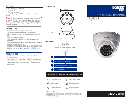
intense light • Periodic cleaning may be required. Use a damp cloth only. Do not use
© 2016 Lorex Corporation
As our product is subject to continuous improvement, Lorex Corporation & subsidiaries reserve the right to modify product design, specifications & prices without notice and without incurring any obligation. E&OE. LNE4162_SERIES_TRIFOLDQSG_EN_R1
ATTENTION - This camera is only compatible with select NVRs. For a list of compatible recorders, please visit https:///support/selfServe.jsp, and search for “Lorex High Definition Cameras Compatibility”.
6. Place the adjustment ring over the dome cover, then place both over the ball camera. Twist the adjustment ring clockwise halfway onto the camera base. Do not tighten all the way.
- 1、下载文档前请自行甄别文档内容的完整性,平台不提供额外的编辑、内容补充、找答案等附加服务。
- 2、"仅部分预览"的文档,不可在线预览部分如存在完整性等问题,可反馈申请退款(可完整预览的文档不适用该条件!)。
- 3、如文档侵犯您的权益,请联系客服反馈,我们会尽快为您处理(人工客服工作时间:9:00-18:30)。
Electrical Characteristics CharacteristicSymNotes MinimumTypical MaximumUnitsFrequency (+25 °C) Nominal Frequency RO3156Af C2,3,4,5868.750869.150MHzRO3156A-1868.800869.100RO3156A-2868.850869.050 Tolerance from 868.95 MHz RO3156AΔf C ±200kHz RO3156A-1±150RO3156A-2±100Insertion Loss IL 2,5,6 1.2 2.0dBQuality Factor Unloaded QQ U 5,6,7620050 Ω Loaded QQ L 850Temperature Stability Turnover TemperatureT O 6,7,8102540°C Turnover Frequencyf O f C kHz Frequency Temperature CoefficientFTC 0.032ppm/°C 2Frequency Aging Absolute Value during the First Year |fA|1<±10ppm/yr DC Insulation Resistance between Any Two Terminals 5 1.0M ΩRF Equivalent RLC Model Motional ResistanceR M 5, 6, 7, 914.5ΩMotional Inductance L M 18.0µH Motional Capacitance C M 2.0fF Shunt Static CapacitanceC O 5, 6, 9 2.1pF Test Fixture Shunt InductanceL TEST2, 715.8nHLid Symbolization (in addition to Lot and/or Date Codes)714 // YWWS•Ideal for European 868.95 MHz Transmitters •Very Low Series Resistance •Quartz Stability•Surface-Mount Ceramic Case with 21 mm 2 Footprint •Complies with Directive 2002/95/EC (RoHS)The RO3156A is a true one-port, surface-acoustic-wave (SAW) resonator in a surface-mount ceramic case. It provides reliable, fundamental-mode, quartz frequency stabilization of fixed-frequency transmitters operating at 868.95 MHz. This SAW is designed specifically for remote-control and wireless security transmitters operating under ETSI-ETS 300 220 in Europe and under FTZ 17 TR 2100 in Germany.Absolute Maximum Ratings RatingValueUnitsCW RF Power Dissipation +5dBm DC Voltage Between Terminals ±30VDC Case Temperature-40 to +85°C Soldering Temperature (10 seconds / 5 cycles max.)260°C868.95 MHzSAW ResonatorRO3156A RO3156A-1RO3156A-2 CAUTION: Electrostatic Sensitive Device. Observe precautions for handling.Notes:1.Frequency aging is the change in f C with time and is specified at +65°C or less. Aging may exceed the specification for prolonged temperaturesabove +65°C. Typically, aging is greatest the first year after manufacture, decreasing in subsequent years.2.The center frequency, f C , is measured at the minimum insertion loss point, IL MIN , with the resonator in the 50Ω test system (VSWR ≤ 1.2:1). The shunt inductance, L TEST , is tuned for parallel resonance with C O at f C . Typically, f OSCILLATOR or f TRANSMITTER is approximately equal to the resonator f C .3.One or more of the following United States patents apply: 4,454,488 and 4,616,197.4.Typically, equipment utilizing this device requires emissions testing and government approval, which is the responsibility of the equipment manufacturer.5.Unless noted otherwise, case temperature T C =+25°C±2°C.6.The design, manufacturing process, and specifications of this device are subject to change without notice.7.Derived mathematically from one or more of the following directly measured parameters: f C , IL, 3dB bandwidth, f C versus T C , and C O .8.Turnover temperature, T O , is the temperature of maximum (or turnover) frequency, f O . The nominal frequency at any case temperature, T C , may be calculated from: f =f O [1-FTC (T O -T C )2]. Typically oscillator T O is approximately equal to the specified resonator T O .9.This equivalent RLC model approximates resonator performance near the resonant frequency and is provided for reference only. The capacitance C O is the static (nonmotional) capacitance between the two terminals measured at low frequency (10MHz) with a capacitance meter. Themeasurement includes parasitic capacitance with "NC” pads unconnected. Case parasitic capacitance is approximately 0.05pF. Transducer parallel capacitance can by calculated as: C P ≈C O -0.05pF.Electrical ConnectionsThe SAW resonator is bidirectional and may be installed with either orientation. The two terminals are interchangeable and unnumbered. The callout NC indicates no internal connection. The NC pads assist with mechanical positioning and stability. External grounding of the NC pads is recommended to help reduce parasitic capacitance in the circuit.Typical Test CircuitThe test circuit inductor, L TEST , is tuned to resonate with the static capacitance, C O , at F C .Typical Application CircuitsEquivalent LC Mode lTemperature CharacteristicsThe curve shown on the right accounts for resonatorcontribution only and does not include LC component temperature contributions.Typical Circuit Board Land PatternThe circuit board land patternshown below is one possible design. The optimum land pattern is dependent on the circuit board assembly process which varies bymanufacturer. The distance between adjacent land edges should be at a maximum to minimize parasitic capacitance. Trace lengths from terminal lands to other components should be short and wide to minimize parasitic series inductances.Case DesignDimensions MillimetersInchesMin NomMaxMin Nom MaxA 4.87 5.0 5.13.191.196.201B 3.37 3.5 3.63.132.137.142C 1.45 1.53 1.60.057.060.062D 1.35 1.43 1.50.040.057.059E .67.80.93.026.031.036F .37.50.63.014.019.024G1.071.201.33.042.047.052。
