SIMETALTR中文版-西门子中国
西门子Sinumerik ShopMill操作培训手册说明书

SinuTrainShopMill 让铣削更轻松培训手册• 2006.08 SINUMERIK2006年08月第4次修订版软件版本号:V06.04西门子股份公司版权所有没有明确的书面许可,不得翻印或传播本文献的内容,亦不得采用影印或将本文献内容制成胶片、磁带、磁碟、幻灯片或其它多媒体制品等方法对本文献加以翻印。
0作为入门指导手册,本文献由以下单位合作完成:西门子股份公司自动化与驱动集团运动控制系统部邮政信箱: 3180, D-91050Erlangen/德国以及R. & S. KELLER GmbHSiegfried Keller, Stefan Nover, Klaus Reckermann, Olaf Anders, Kai Schmitz邮政信箱:131663, D-42043 Wuppertal/德国订货号:6FC5095-0AA50-0RP2ShopMill培训手册前言如何更快地从图纸到工件?迄今为止,数控生产主要采用复杂、抽象的代码进行NC编程,因而只有专业人员才能对其进行操作。
但是实际上,由于每一位熟练工人都堪称专业人士,因而也能够利用传统机械加工中所积累的丰富经验处理最为棘手的任务-尽管采取的方法通常很不经济。
所以,有必要找到一种方法,使这些技术专家们能够有效地将其经验应用到NC机床生产中。
西门子公司推出的ShopMill工具,不但使操作人员省却了编码之苦,亦使他们拥有了新一代的 SINUMERIK 控制系统。
西门子提供的解决方案是:建立一个工作计划,而非一段程序。
通过建立与操作人员水平相当且包含具体操作要求的工作计划,ShopMill的用户能够将其专业知识真正运用到加工过程当中,同时亦不会荒废实际的技能。
由于ShopMill能够建立强大的集成式运行轨迹,即使最复杂的轮廓和工件亦可轻松制得。
因此:可借助 ShopMill 更加快捷地从图纸向工件转移!尽管ShopMill 简单易学,但本培训教程有助您更快更好地掌握ShopMill的各项功能。
西门子-simosvert masterdrives 矢量控制 使用大全-上册说明书

矢量控制版本:AGsimovert使用大全(上册)我们保留更改功能、技术数据、标准、附图及参数的权利。
西门子电气传动有限公司对于6SE70书本型和装机装柜型装置提供电压等级为400V的产品,对于6SE71变频调速柜提供电压等级为400V、500V、690V全功率范围的产品。
对增强书本型装置(Compact PLUS units),暂不在西门子电气传动有限公司供货范围内,如果您需要,请与当地西门子销售机构联系。
如果您需要其他电压等级和功率的产品以及多电机传动的直流母线方案,也请与当地的西门子销售机构联系。
未经授权复制,传播或使用本文件及其内容是不允许的。
违犯者将负赔偿责任,所有权力,包括专利权授予的权力及应用型号或设计的注册权将被保留。
我们已经校对了本出版物的内容,他与其中所介绍硬件及软件内容是一致的。
但是,仍然有可能存在差异,因此,我们不能保证他们完全相同。
本出版物所提供的资料将定期回顾,并且任何必要的更正将在接下来的发行中执行。
为Siemens 注册商标® 欢迎在任何时间提出改进建议。
SIMOVERT西门子电气传动有限公司版权所有不得翻印上 册 系统说明 配置和接线举例 依照EMC 导则进行 传动装置设计的说明 功能块和参数 参数设置 参数设置步骤SIMOVERT MASTERDRIVES矢量控制使用大全功 能 通 讯 版本: AG6SE7085-0QX60感谢您使用西门子公司的传动产品!西门子公司变频传动产品SIMOVERT MASTERDRIVES自在中国市场推出以来,与西门子公司的其他产品一样,得到了广大用户的认同和使用。
新推出的SIMOVERT MASTERDRIVES Vector Control系列变频传动产品具有更大允许电压波动范围、更小的体积、更强的通讯能力并可同直流传动系统100% 的兼容。
我们相信,新系列产品将会在多种工业、商用及民用领域中得到更广泛的应用。
为此,我们对西门子公司的广大用户及关心西门子公司产品的人士表示由衷的感谢!为了用户能够更深入地了解、使用西门子公司SIMOVERT MASTERDRIVES Vector Control变频传动产品,我们根据英文版使用大全,翻译出这本中文版的使用大全。
西门子 SIWAREX FTC 装置手册说明书

前言西门子SIWAREX®FTC装置手册状态:2005年1月25日前言SIWAREX FTC警告和安全术语本手册包含有为了保护你的人身安全和防止损坏装置或周围环境而应该遵守的注意事项。
这些注意事项由一个警告三角形表示,根据不同的危险程度代表下列意义:危险意思是:如果未能认真遵守相应的安全预防措施,将肯定会导致严重的财产损失、严重的人身伤害、甚至死亡。
警告意思是:如果未能认真遵守相应的安全预防措施,将能够导致严重的财产损失、严重的人身伤害、甚至死亡。
小心意思是:如果未能认真遵守相应的安全预防措施,将能够导致财产损失或轻微的伤害。
小心意思是:如果未能认真遵守相应的安全预防措施,将能够导致财产损失。
注意指的是需要加以特别关注的重要信息;这些信息涉及到产品、产品的处置或资料中的一个对应段落。
合格人员装置的安装和操作只能由合格人员执行。
在本手册的范围内,从技术安全意义出发的合格人员指的是这样一些人:他们有资格按照适用于技术安全标准,从事所有装置、系统和回路的安装、接地和标识工作。
预定用途警告 本装置只能利用样本和技术描述中规定的替换件,而且只能利用由西门子公司批准或建议的外国或外部装置和部件。
产品的安全可靠、无故障的运行不仅取决于合适的运输,还依赖于合适的贮存、组装、安装、操作和维护。
产品牌号 / 商标SIWAREX®、SIMATIC®、SIMATIC HMI®和SIMATIC NET®都是西门子AG 公司的注意商标。
任何第三方为了他们自己的目的而使用本文件中涉及商标的其它名称都将侵犯商标所有人的权利。
版权 © 西门子AG 2003;版权所有,不得翻印。
未经明确许可,严禁传播或复制本资料,严禁使用和披露本资料的内容。
违者应对相关损失承担法律责任。
保留所有权利,包括由一种实用新型或设计的专利许可或注册所形成的权利。
西门子AG自动化与驱动集团SIWAREX 称重系统A&D PI 14Östliche Rheinbrückenstr. 50D-76187 Karlsruhe (卡尔斯鲁厄) 责任放弃声明 我们已经校验了本手册中的内容与所述硬件和软件的一致性。
SINAMICS_Startdrive_V16功能在TIA博途的应用
第58卷0引言SI N A M I CS St ar t dr i ve 可以用来在TI A Por t al中进行西门子驱动的配置和参数设置。
可进行以下任务:将驱动嵌入项目,作为单个驱动或将驱动与上级控制系统进行联网;对所用功率部件、电机和编码器进行参数配置(包括最新的S210系列驱动产品);支持配置多种控方式来控制驱动;支持驱动专用功能(如自由功能块和工艺控制器)等扩展参数设置;通过驱动控制面板在线测试驱动参数设置;出现故障时执行诊断。
1概述1.1软件简介SI N A M I CS St ar t dr i ve 调试软件是将西门子驱动器硬件集成到TI A Por t al工程框架中的理想工具。
借助最新版本的SI N A M I CS St ar t dr i ve V 16,西门子正在扩展自动化平台上可用的驱动硬件产品组合。
该软件有两个版本:St ar t dr i ve Bas i c 和St ar t dr i ve A dvanced 。
Bas i c 版包括驱动设备的调试和诊断功能。
A dvanced 版除了包含Bas i c 版的所有功能外,还包含SI N A M I CS S120,G 120和S210的集成安全验收测试功能。
1.2新功能介绍SI N A M I CS St ar t dr i ve 调试工具是自动化设备调试的关键软件。
利用博途平台,驱动器和控制器之间的便捷交互使SI M A TI C 控制器和SI N A M I CS 驱动器轻松完成运动控制项目的调试。
从V 16版本开始,其功能得到了进一步增强。
在集成了SI N A M I CS S120多轴系统CU 320-2PN 之后,从V 16开始也支持组态和调试CU 310-2PN 及PM 240-2。
CU 310-2PN 是S120高端伺服驱动系统的单轴控制单元。
最新推出的SI M A TI C 驱动运动控制器(Si m at i c D r i ve Cont r ol l er )的驱动控制也集成在St ar t dr i ve 调试工具中。
SINUTRAIN 培训编程入门

CHS
SinuTrain SINUMERIK 培培培培培
入门
版本 01.05
A5E 0039 1242 – 001
当前有效的附加信息可在以下互联网网址获取: /mc/sinutrain 本用用用 WinWord V 8.0 培辑制作
CHS/iv
© 西门子股份有限公司2005版权所有。 SinuTrain 入门 (BAK) – 版本 01.05
01.05
培训和编程 (CHS) 目录
SinuTrain
培训和编程 (CHS)
1 安装 ...........................................................................................................................................CHS/1-7 1.1 系统前提条件 ........................................................................................................................CHS/1-7 1.2 安装 CD 光盘 ........................................................................................................................CHS/1-7 1.3 第一次启动前的设置 ............................................................................................................CHS/1-11 1.4 自动许可管理器(ALM) ....................................................................................................CHS/1-13 1.5 文献资料..............................................................................................................................CHS/1-14 1.6 卸载 .....................................................................................................................................CHS/1-14 2 键盘和操作 .............................................................................................................................CHS/2-15 2.1 SinuTrain 启动 ....................................................................................................................CHS/2-15 2.2 示例程序..............................................................................................................................CHS/2-18 2.3 通过计算机标准键盘操作.....................................................................................................CHS/2-20 2.4 通过 SinuTrain 培训键盘(USB)操作 ...............................................................................CHS/2-20 2.5 打印 .....................................................................................................................................CHS/2-21 2.6 使用 CAD 阅读器(可选) ..................................................................................................CHS/2-21 2.7 退出 SinuTrain ....................................................................................................................CHS/2-21 2.8 与操作 802D 时的区别 ........................................................................................................CHS/2-22 2.8.1 数据交换设置 ..................................................................................................................CHS/2-22 2.8.2 运行 SinuTrain - 环境 ......................................................................................................CHS/2-22 2.8.3 HMI 802D 操作 ...............................................................................................................CHS/2-24 2.8.4 通过 HMI 802D 在 SIM_LOCAL_NCK 和硬盘之间进行数据交换 ....................................CHS/2-26 2.8.5 与控制装置 802D 的数据交换 .........................................................................................CHS/2-26 2.8.6 从 802D系统进行 打印 ....................................................................................................CHS/2-27
西门子 说明书
SIMATICS7/HMISIMATIC Automation Tool SDK V3.1 SP2 Product informationProduct InformationSiemens AG Division Digital Factory A5E45252984-AAⓅ 10/2018 Subject to changeCopyright © Siemens AG 2018.All rights reservedLegal informationWarning notice systemThis manual contains notices you have to observe in order to ensure your personal safety, as well as to preventdamage to property. The notices referring to your personal safety are highlighted in the manual by a safety alertsymbol, notices referring only to property damage have no safety alert symbol. These notices shown below aregraded according to the degree of danger.indicates that death or severe personal injury will result if proper precautions are not taken.WARNINGindicates that death or severe personal injury may result if proper precautions are not taken.CAUTIONindicates that minor personal injury can result if proper precautions are not taken.NOTICEindicates that property damage can result if proper precautions are not taken.If more than one degree of danger is present, the warning notice representing the highest degree of danger willbe used. A notice warning of injury to persons with a safety alert symbol may also include a warning relating toproperty damage.Qualified PersonnelThe product/system described in this documentation may be operated only by personnel qualified for the specifictask in accordance with the relevant documentation, in particular its warning notices and safety instructions.Qualified personnel are those who, based on their training and experience, are capable of identifying risks andavoiding potential hazards when working with these products/systems.Proper use of Siemens productsNote the following:WARNINGSiemens products may only be used for the applications described in the catalog and in the relevant technicaldocumentation. If products and components from other manufacturers are used, these must be recommendedor approved by Siemens. Proper transport, storage, installation, assembly, commissioning, operation andmaintenance are required to ensure that the products operate safely and without any problems. The permissibleambient conditions must be complied with. The information in the relevant documentation must be observed. TrademarksAll names identified by ® are registered trademarks of Siemens AG. The remaining trademarks in this publicationmay be trademarks whose use by third parties for their own purposes could violate the rights of the owner. Disclaimer of LiabilityWe have reviewed the contents of this publication to ensure consistency with the hardware and softwaredescribed. Since variance cannot be precluded entirely, we cannot guarantee full consistency. However, theinformation in this publication is reviewed regularly and any necessary corrections are included in subsequenteditions.Table of contents1 Components of the SIMATIC Automation Tool SDK (4)Components of the SIMATIC Automation Tool SDK 1 The SIMATIC Automation Tool Software Development Kit (SDK) consists of the followingcomponents:●Setup application for installing the SDK●SIMATIC Automation Tool Application Programming Interface (API): a set of .NETinterfaces, classes, and methods to perform network and device operations● A Windows installer package to use in creating a setup for your users. Your users caninstall your custom application from the setup you create. The installer provides for asilent installation of the API and S7 communication components with no licenserequirement.●Product Information●Installation Notes●User Guide●Totally Integrated Automation UPDATER (TIA Software Updater) for performing futureupdates to the SDK。
西门子(Siemens) sirius技术支持指南说明书
Customer Self Repair (CSR)Maintenance and Service GuideFirst Edition /September 2021COPYRIGHT INFORMATIONNo part of this manual, including the products and software described in it, may be reproduced,transmitted, transcribed, stored in a retrieval system, or translated into any language in any form or by any means, except documentation kept by the purchaser for backup purposes, without the express written permission of ASUSTeK COMPUTER INC.(“ASUS”).ASUS PROVIDES THIS MANUAL “AS IS” WITHOUT WARRANTY OF ANY KIND, EITHER EXPRESS OR IMPLIED,INCLUDING BUT NOT LIMITED TO THE IMPLIED WARRANTIES OR CONDITIONS OF MERCHANTABILITY OR FITNESS FOR A PARTICULAR PURPOSE. IN NO EVENT SHALL ASUS, ITS DIRECTORS, OFFICERS, EMPLOYEES OR AGENTS BE LIABLE FOR ANY INDIRECT, SPECIAL, INCIDENTAL, OR CONSEQUENTIAL DAMAGES(INCLUDING DAMAGES FOR LOSS OF PROFITS, LOSS OF BUSINESS, LOSS OF USE OR DATA, INTERRUPTION OF BUSINESS AND THE LIKE), EVEN IF ASUS HAS BEEN ADVISED OF THE POSSIBILITY OF SUCH DAMAGES ARISING FROM ANY DEFECT OR ERROR IN THIS MANUAL OR PRODUCT.Products and corporate names appearing in this manual may or may not be registered trademarks or copyrights of their respective companies, and are used only for identification or explanation and to the owners’ benefit, without intent to infringe.SPECIFICATIONS AND INFORMATION CONTAINED IN THIS MANUAL ARE FURNISHED FOR INFORMATIONAL USE ONLY, AND ARE SUBJECT TO CHANGE AT ANY TIME WITHOUT NOTICE, AND SHOULD NOT BE CONSTRUED AS A COMMITMENT BY ASUS. ASUS ASSUMES NO RESPONSIBILITY OR LIABILITY FOR ANY ERRORS OR INACCURACIES THAT MAY APPEAR IN THIS MANUAL, INCLUDING THE PRODUCTS AND SOFTWARE DESCRIBED IN IT.Copyright © 2020 ASUSTeK COMPUTER INC. All Rights Reserved.LIMITATION OF LIABILITYCircumstances may arise where because of a default on ASUS’ part or other liability, you are entitled to recover damages from ASUS. In each such instance, regardless of the basis on which you are entitled to claim damages from ASUS, ASUS is liable for no more than damages for bodily injury (including death) and damage to real property and tangible personal property; or any other actual and direct damages resulted from omission or failure of performing legal duties under this Warranty Statement, up to the listed contract price of each product.ASUS will only be responsible for or indemnify you for loss, damages or claims based in contract, tort or infringement under this Warranty Statement.This limit also applies to ASUS’ suppliers and its reseller. It is the maximum for which ASUS, its suppliers, and your reseller are collectively responsible.UNDER NO CIRCUMSTANCES IS ASUS LIABLE FOR ANY OF THE FOLLOWING: (1) THIRD-PARTY CLAIMS AGAINST YOU FOR DAMAGES; (2) LOSS OF, OR DAMAGE TO, YOUR RECORDS OR DATA; OR (3) SPECIAL, INCIDENTAL, OR INDIRECT DAMAGES OR FOR ANY ECONOMIC CONSEQUENTIAL DAMAGES (INCLUDING LOST PROFITS OR SAVINGS), EVEN IF ASUS, ITS SUPPLIERS OR YOUR RESELLER IS INFORMED OF THEIR POSSIBILITY.SERVICE AND SUPPORTVisit our multi-language website at:https:///support/Table of Contents Disclaimer (4)Safety precautions (4)Installation tools (5)Before disassembly (5)Removing the base cover (6)Installing a RAM module (9)Installing an M.2card(SSD) (14)DisclaimerASUS is not responsible for direct, indirect, intentional or unintentional damages resulting from improper installation and operation.Safety precautions•Keep liquids or moisture away from your Notebook PC before installing or removing any components.•Place your Notebook PC on a stable surface before installing or removing any components. •Detach the clip or flap before removing the signal cables to prevent damage.•Disconnect the power plug by pulling the plug evenly to avoid damage. Ensure to connect the signal cables in the correct orientation.•Disconnect all power cables and remove the battery pack (if applicable) before cleaning your Notebook PC with liquid detergent to avoid risk of electric shock.•Disconnect all power cables and remove the battery pack (if applicable) before installing or removing any components. Be sure to thoroughly to read and follow the instructions in the manual.•To avoid Electrostatic Discharge (ESD) damage the electric components inside your computer, before handling components, use a grounded wrist strap or touch a safely grounded object to prevent electric products damaged by the electrostatic discharge.Please refer to Electrostatic Discharge (ESD) Protection Notes.•Keep liquids or moisture away from your Notebook PC to avoid short circuiting.•Hold components by the edges to avoid touching the Integrated Circuits (ICs).•Before re-connecting the AC power, ensure all components are properly installed.•Reduce the risk of fire or explosion by avoiding incompatible power adapters or batteries. Use only certified power adapters or batteries supplied by ASUS or authorized retailers.•Ensure the correct screw models are re-installed to your Notebook PC to prevent damage. Protection of Stored DataFor Your important data, please make periodic back-up copies of all the data stored on the hard disk or other storage devices as a precaution against possible failures, alteration, or loss of the data. ASUS AND ITS AFFILIATES WILL NOT BE HELD LIABLE FOR ANY OF YOUR CONFIDENTIAL, PROPRIETARY OR PERSONAL DATA NOR ANY LOST OR CORRUPTED DATA, PROGRAMS OR SOFTWARE. IF YOUR DATA IS ALTERED OR LOST DUE TO ANY TROUBLE, FAILURE OR MALFUNCTION OF THE PRODUCT AND THE DATA CANNOT BE RECOVERED, WE SHALL NOT BE LIABLE FOR ANY DAMAGE OR LOSS TO DATA, SYSTEM, NETWORK, OR ANY OTHER DAMAGE RESULTING THEREFROM. WHEN COPYING OR TRANSFERRING YOUR DATA, PLEASE BE SURE TO CONFIRM WHETHER THE DATA HAS BEEN SUCCESSFULLY COPIED OR TRANSFERRED PRIOR TO PROVISIONING OF SERVICES BY US. WE DISCLAIM ANY LIABILITY FOR THE FAILURE TO COPY OR TRANSFER THE DATA CORRECTLY AND WILL HAVE NO LIABILITY FOR ANY ACTS OR OMISSIONS, INCLUDING NEGLIGENCE, BY ASUS OR A THIRD-PARTY SERVICE PROVIDER.Installation tools#1Before disassemblyA.Before your disassembly, we strongly recommend that youprepare a smartphone or other handheld camera. Duringdisassembly, use your camera to take photos to help youremember the order of assembly and location of parts.B.When lifting the base cover off, slowly and carefully open so theangle is as small as possible. To avoid damaging the cables,please confirm they are disconnected before opening the basecover completely.C.After you open the base cover, be sure to disconnect the batterycable first.D.When replacing components, if any materials, cables, tapes andothers were touched or moved, please return it to its originallocation before proceeding.E.Avoid using too much force when fastening screws to preventhardware damage.CDEBA Screwdriver Non-conductive pry tool Tweezers Anti-static glovesA.Remove the rubber(s) from the Notebook PC ’s base cover.B. Remove the screw(s) from the Notebook PC ’s base cover.Removing the base coverNOTE : The appearance of your Notebook PC ’s bottom view may vary per model.Lefty -Loosey Righty -Tighty #1#1#1Please loosen the pop-open screw last,it cannot be removed from cover.Please tighten the pop-open screw first.e the non-conductive pry tool to lift open the indicated area of thebase cover as shown in the illustration.Disassembly steps:IMPORTANT!Avoid sliding the non-conductive pry toolalong the side of yourNotebook PC to prevent damage.StartD.Pull out the base cover and remove it completely from your Notebook PC.Installing a RAM moduleUpgrade the memory capacity of your Notebook PC by installing a RAM (Random Access Memory) module in the memory module compartment. The following steps show you how to install a RAM module into your Notebook PC:WARNING! Disconnect all the connected peripherals, any telephone or telecommunication lines and power connector (such as external power supply, battery pack, etc.) before removing the base cover.IMPORTANT! Visit an authorized service center or retailer forinformation on RAM module upgrades for your Notebook PC. Onlypurchase RAM modules from authorized retailers of this Notebook PC to ensure maximum compatibility and reliability.NOTE:•The appearance of your Notebook PC’s bottom view and RAMmodule may vary per model but the RAM module installationremains the same.•It is recommended that you install the RAM module underprofessional supervision. You may also visit an authorized servicecenter for further assistance.A.Before handling components, wear anti-static gloves to avoid damaging them due to static electricity.B.Remove the base cover.C.Disconnect the cable from the battery connector.NOTE : For more details, refer to the removing the base cover section in this manual.Disassembly steps:e the non-conductive pry tool to push iron sheet.e thenon-conductive pry tool to disconnect battery connector.Disassembly steps:1.Tear off the ABSORBER from RAM. Please keep this part, it will be reused for new RAM installation.2.Unlock and remove the RAM module, then tear off the ABSORBER from RAM back side. Please keep this part, it will be reused for newRAM installation.D.Removethe RAM module.NOTE :If there is material pasted on the RAM, when you replace RAM, please paste the material on the new RAM.(Not included specificationlabel.)E.Paste the ABSORBERS to new RAM front and back side.F.Align and insert the new RAM module at 30°into the memory slot.G.Once properly inserted, push down the RAM module until it clicks in place.30°F GH.Please follow the below steps to attach the battery connector.15~30K. Secure the base cover in place using the screws.I. Install the base cover at a slight tilt at upper side first, and then pressthe upper side of base cover to fix from right to left.J. Put the base cover down slowly, and then press left and right side of basecover to fix, and press lower side of base cover to fix.Lefty -Loosey Righty -Tighty#1#1#1Please tighten the pop-open screw first.L. Plug the rubber(s) back to the Notebook PC’s base cover.Installing an M.2 card (SSD)Refer to the following steps when installing a compatible M.2 card (SSD) in your Notebook PC:IMPORTANT! Purchase your M.2 card from authorized retailers ofthis Notebook PC to ensure maximum compatibility and reliability.WARNING! Disconnect all the connected peripherals, any telephoneor telecommunication lines and power connector (such as externalpower supply, battery pack, etc.) before removing the base cover.NOTE:•The appearance of your Notebook PC’s bottom view and M.2 cardmay vary per model but the module installation remains the same.•It is recommended that you install the M.2 card underprofessional supervision. You may also visit an authorized servicecenter for further assistance.A.Before handling components, wear anti-static gloves to avoid damaging them due to static electricity.B.Remove the base cover.C.Disconnect the cable from the battery connector.NOTE : For more details, refer to the removing the base cover section in this manual.Disassembly steps:1.Use the non-conductive pry tool to push iron sheet.e thenon-conductive pry tool to disconnect battery connector.Disassembly steps:1.Remove the screw*1pc and M.2 card (SSD).NOTE :If there is material pasted on the M.2 card (SSD), when you replace M.2 card (SSD), please paste the material on the new M.2 card (SSD).(Notincluded specification label.)Assembly steps:1. Align and insert the new M.2 card into the module slot.2. Secure the M.2 card in place by fastening the screw.12F.Please follow the below steps to attach the battery connector.15~30I. Secure the base cover in place using the screws.G. Install the base cover at a slight tilt at upper side first, and then pressthe upper side of base cover to fix from right to left.H. Put the base cover down slowly, and then press left and right side of basecover to fix, and press lower side of base cover to fix.Lefty -Loosey Righty -Tighty#1#1#1Please tighten the pop-open screw first.J. Plug the rubber(s) back to the Notebook PC’s base cover.。
西门子SIPROTEC 4 Mini SMART Device技术手册说明书

SIPROTEC 4 Mini SMART Device 微机综合保护测控装置技术手册3.2版/eaSIPROTEC 4 Mini SMART Device概述Mini SMART Device保护专为10kV配电和工业用电系统设计,符合国内设计和使用习惯。
它提供了大屏幕显示、全中文人机界面、操作箱功能、独立的测量CT,同时又传承了西门子保护严谨和灵活的风格,是一款极具性价比的产品。
前部的USB口为用户提供了远程维护和故障诊断的便利。
用户只需将U盘插入装置,相关的故障录波和跳闸信息会被导出,我们的售后服务人员会分析故障的类型并指导用户处理现场。
装置配置的下装和软件的升级都可以通过U盘完成。
7SJ686 系列装置的定值完全按照国内用户习惯设定,如:有控制字投退功能;所有开入和开出都有预定义,用户只要从面板上输入定值装置就可正常工作。
集成的可编程逻辑工具(CFC)允许用户实现特殊的保护、联闭锁功能和自定义的信息。
用户可以通过更改跳线使保护适用于110V DC或220VDC的现场直流电源、1A或5A的CT,同时装置支持直流、交流操作箱功能。
装置支持4组定值,可通过开入量、通讯规约、LCD面板来切换。
功能范围●3段定时限+1段反时限过流保护● 复合电压闭锁过流●3段定时限+1段反时限零序过流保护●2段定时限+1段反时限负序过流保护●2段过电压+2段低电压保护● 手合故障加速保护●2次谐波闭锁过流●4段低压减载●4段低频减载● 重合闸前加速后加速●2段零序过压保护●2段过负荷保护●FC回路过流闭锁跳闸功能● 充电保护●2次重合闸●5组非电量保护● 小电流选线功能●3段定时限+1段反时限无方向过流保护● 复合电压闭锁过流●3段定时限+1段反时限零序无方向过流保护●2段定时限+1段反时限负序过流保护●2段过电压+2段低电压保护● 手合故障加速保护●4段低压减载●4段低频减载●2段零序过压保护●2段过负荷保护● 低压侧零序过流3段定时●5组非电量保护●FC回路过流闭锁跳闸功能控制功能/可编程逻辑● 灵活配置的控制对象● 前面板单线图显示及操作功能●CFC实现扩展的用户定义联闭锁逻辑基本硬件● 4VT, 4CT● 6个开入,8个开出,1个装置告警接点● 9个开入,6个开出,0个装置告警接点● 9个开入,4个开出,1个装置告警接点● 1个RS485 或以太网口●3段定时限+1段反时限无方向过流保护●3段定时限+1段反时限零序无方向过流保护●2段定时限+1段反时限负序过流保护●2段过电压+2段低电压保护● 手合故障加速保护●4段低压减载●4段低频减载● 热过负荷保护● 欠电流保护● 电机启动保护● 电机堵转保护● 电动机重启抑制保护●2段零序过压保护●2段过负荷保护●5组非电量保护●FC回路过流闭锁跳闸功能● 运行测量值U、I、P、Q、cos φ、f…● 电能测量值Wp、Wq● 跳合闸回路监视●VT / CT回路断线监视● 最近20次故障录波● 线路有无压监测● 相序监视● 控制回路断线监视● 冷负荷启动监视扩展硬件● 3 路测量CT● 交流或直流操作板通讯● 1个RS485 或1个以太网口●IEC 60870-5-103(RS485或以太网)●IEC 61850 MMS & GOOSE●Modbus(RS485 或以太网)●DIGSI 4 (USB, RS485 或以太网)●SNTP 网络对时1SIPROTEC 4 Mini SMART Device选型和订货数据2SIPROTEC 4 Mini SMART Device 6个开入,8个开出装置背端子图3SIPROTEC 4 Mini SMART Device9个开入,6个开出装置背端子图,加个图4SIPROTEC 4 Mini SMART Device24 VDC~48 VDC供电,9个开入,4个开出装置背端子图5SIPROTEC 4 Mini SMART Device外形尺寸( mm)6版权所有:所有所使用的产品名称均为西门子公司的商标或产品名,受法律保护。
西门子SIMOTION TO Trace 功能操作指南说明书

/CN/view/zh/109482943C o p y r i g h t ãS i e m e n s A G C o p y r i g h t y e a r A l l r i g h t s r e s e r v e d目录1概述 .................................................................................................................... 32功能描述 ............................................................................................................. 42.1TO Trace 功能描述 .............................................................................. 42.2TO Trace 功能调用 .............................................................................. 42.3TO Trace 功能配置 .............................................................................. 52.4TO Trace 功能执行与结果查看 (7)C o p y r i g h t ãS i e m e n s A G C o p y r i g h t y e a r A l l r i g h t s r e s e r v e d1概述SIMOTION SCOUT 软件中提供了很多诊断工具,比如System Trace 、Device Trace 、Task Trace 等,可以对系统状态、TO 状态、程序任务状态等进行全方位监视。
西门子ms 中文

表 2.1
步骤 说明
1.
在 HTML 页面可以下子这个数据库,并将其存在
硬盘上。
2.
打开 STEP 7 Micro/WIN
3.
在项目目录里的“数据库”上点击鼠标右键.
选择“添加/删除数据库...”
备注 MicroSet_add.mwl
4.
点击左边的“添加”按钮
在硬盘上,找到存放数据库的位置,并选定。
用户界面 -"MicroScale_V20"数据库的处理值,系统信息和错误信息的编辑提交。 -所有数值的按照功能细分的状态表和符号表。 -状态表和符号表的储存区的变量地址动态调整。
控制功能 -输入 SIWAREX MS 的参数和处理值的编辑选项。这个,SIWAREX MS 可以通过 S7-200 进
表 3-2
编 名称 号
转移 数 据 描述/注释 类型
1. EN
转入 布尔
2. FirstVB_POINTER 转入 字节
3. DR_POINTER
转入 字节
4. Command_Code 转入 字节
5. DR
转入 字节
6. Offset
转入 字节
激活子程序
is called with the "SM0.0" special memory bit. 指“MicroScale_V20"数据库的缓冲。 被转换为指示器,并由“&”标记引导(如,& VB0)。 需要缓冲大小为 26 字节。 缓冲容量与由和数据库关联的 Excel 表生成的 "MS"表一致。 用于“MicroScale_additional”的内部处理,同时 为用户提供“MicroScale_V20”的处理值和状态 值,以用于进一步处理。
西门子(中国)有限公司新一代数控系统SINUMERIK ONE

/ 现代金属加工3592021第06期 • 现代制造Supplement 特别报道伊斯卡刀具国际贸易(上海)有限公司全新NEOLOGIQ 系列大进给铣刀NEOFEED 西门子(中国)有限公司新一代数控系统SINUMERIK ONE 数字化原生的SINUMERIK ONE 是西门子新一代数控系统。
新的硬件使NC 性能和PLC 性能表现更为强劲,结合创新的功能将进一步提高机床的加工速度、加工精度和表面质量。
SINUMERIK ONE 提供的数字化双胞胎,将帮助机床制造厂商和机床用户,改变工作流程,降低新产品开发的费用和风险,缩短上市时间,助力机床的数字化转型。
借助数字化双胞胎,SINUMERIK ONE 实现了虚拟与现实无缝交互的工程方式,有效地降低了产品研发的费用和风险,缩短产品上市时间,使得机床制造商和机床使用者都可以从中获益。
SINUMERIK ONE 凭借其全新硬件平台,丰富创新性功能,进一步提高了加工速度、加工精度和加工质量,树立了生产力的新标准。
既集成又创新的SINUMERIK ONE 将成为西门子持续助力中国高端机床发展的产品。
展位号:W3-A002大进给铣刀NEOFEED ,夹持双面方形刀片,为用户提供了价格公道的成本节约解决方案。
特别设计的带8个切削刃的硬质合金可转位刀片设计装夹于楔形定位槽,牢靠的夹紧确保铣刀能负荷重载,以实现更高的切削参数,提高生产率。
能在各种铣削应用中实现大进给及中速进给铣削,满足各种面铣需求。
铣刀片长宽为12 mm ,断屑槽为HP 的刀片用于奥氏体不锈钢件及高温合金件的加工;断屑槽为T 的刀片用于钢件、铁素体不锈钢件、马氏体不锈钢件,铸铁件及淬硬钢的加工。
面铣刀范围为50~100 mm 。
展位号:E2-B301江苏亚威机床股份有限公司 HPML-30510冲割复合机亚威HPML-30510冲割复合机是面向高端钣金市场推出的复合加工利器,产品糅合了数控转塔冲床和激光切割机两种机型加工优势,通过西门子平台整合集成技术,实现了冲压工艺和激光切割工艺两大分类技术的无缝对接、功能实现互补,并且集成多轴自动攻丝功能,可以实现M3-M8多种螺纹的自动攻丝,无铁屑残留,加工效率高。
西门子 SIWAREX U 设备手册说明书

SIWAREX® U设备手册版本:2007年12月用于订货号为7MH4950-1AA01和7MH4950-2AA01的模块警告和安全术语本手册包含有为了保护您的人身安全和防止损坏装置或周围环境而应该遵守的注意事项。
这些注意事项由一个警告三角形表示,根据不同的危险程度代表下列意义:危险意思是:如果未能认真遵守相应的安全预防措施,将肯定会导致严重的财产损失、严重的人身伤害、甚至死亡。
警告意思是:如果未能认真遵守相应的安全预防措施,将能够导致严重的财产损失、严重的人身伤害、甚至死亡。
小心意思是:如果未能认真遵守相应的安全预防措施,将可能导致财产损失或轻微的伤害。
小心意思是:如果未能认真遵守相应的安全预防措施,将可能导致财产损失。
注意指的是需要加以特别关注的重要信息;这些信息涉及到产品、产品的处置或资料中的一个对应段落。
合格人员装置的安装和操作只能由合格人员执行。
在本手册的范围内,从技术安全意义出发的合格人员指的是这样一些人:他有资格按照适用于技术安全标准,从事所有装置、系统和回路的安装、接地和标识工作。
警告本装置只能利用样本和技术描述中规定的替换件,而且只能利用由西门子公司批准或建议的外国或外部装置和部件。
产品的安全可靠、无故障的运行不仅取决于合适的运输,还依赖于合适的贮存、组装、安装、操作和维护。
产品牌号 / 商标SIWAREX®、SIMATIC®、SIMATIC HMI®和SIMATIC NET®都是西门子AG 公司的注意商标。
任何第三方为了个人目的而使用本文件中涉及商标的其它名称都将侵犯商标所有人的权利。
版权 © 西门子AG 2003;版权所有,不得翻印。
未经明确许可,严禁传播或复制本资料,严禁使用和披露本资料的内容。
违者应对相关损失承担法律责任。
保留所有权利,包括由一种实用新型或设计的专利许可或注册所形成的权利。
西门子(中国)有限公司上海浦东新区浦东大道1号船舶大厦7楼电话:(021)38892381传真:(021)38893264.免责声明我们已经校验了本手册中的内容与所述硬件和软件的一致性。
SICAM Studio 配置工具使用手册说明书
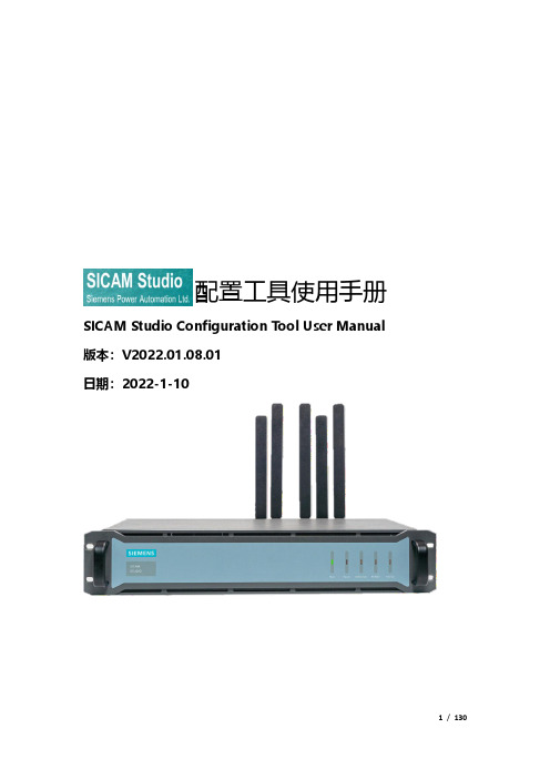
配置工具使用手册SICAM Studio Configuration Tool User Manual 版本:V2022.01.08.01日期:2022-1-10前言SICAM Studio Configuration Tool(简称“SSCTool”)是西门子电力自动化有限公司专门为SICAM Studio产品研发的专业配置工具软件,本文档主要是介绍SSCTool工具软件的使用。
※SSCTool能做什么?☆SSCTool运行于XP及以上windows操作系统,直接运行(无需安装)。
☆配置南向协议(数据采集)和北向协议(数据服务)。
☆数据定义、参数配置,配置下载、程序更新等管理功能。
☆监视关键的运行数据及状态、通讯报文查看及分析、控制与模拟操作。
☆附件功能:远程隧道方式维护、系统软件配置与维护。
※术语SSCTool —SICAM Studio配置工具软件设备—SICAM Studio装置—接入通信的采集设备、第三方系统或平台端口—串口或网络通信端口,包括RS232/RS485/TCP/UDP等系统—SCADA软件,上位机组态软件,用于现场级的监控规约—通讯协议,双方通讯的接口数据格式测点—协议解析的数据变量,包括模拟量、数字量、控制量※主要功能描述及索引☆工程管理:对工程项目的配置管理,单个工程中可以管理单个或多个SICAM Studio设备,支持多个工程的管理;工程文件或目录可以压缩备份,拷贝可直接加载使用,利用工程维护。
(参考“第1章“内容)☆模板定义:在端口配置通信前做的工作,已有的模板可以直接使用,积累更多的模板库方便工程直接的使用,支持导入/导出文件存储、复制和备份。
(参考“第2章“内容,更多的模板定义介绍参照《模板定义手册》)☆端口配置南向协议(数据采集):根据工程项目的实际需要,进行端口数据采集的通信配置,利用已定义的模板快速的实现端口的通信配置工作,重点是通讯参数设置。
(参考“3.2章节“内容)☆端口配置北向协议(数据转发):根据工程项目的实际需要,进行端口数据转发配置,配置转发的数据点表,提供了方便、高效的快速定义功能(复制、粘贴、填充等),支持从excel表中整体复制、粘贴,重点是利用好这些快速定义功能。
Siemens 编程与操作手册说明书

2.4.7Tapping with compensating chuck - CYCLE840ProgrammingCYCLE840 (RTP, RFP, SDIS, DP, DPR, DTB, SDR, SDAC, ENC, MPIT, PIT, AXN) ParametersParameter Data type DescriptionRTP REAL Retraction plane (absolute)RFP REAL Reference plane (absolute)SDIS REAL Safety clearance (enter without sign)DP REAL Final drilling depth (absolute)DPR REAL Final drilling depth relative to the reference plane (enter withoutsign)DTB REAL Dwell time at thread depth (chip breakage)SDR INT Direction of rotation for retractionValues: 0 (automatic direction reversal), 3 or 4 (for M3 or M4) SDAC INT Direction of rotation after end of cycleValues: 3, 4 or 5 (for M3, M4 or M5)ENC INT Tapping with/without encoderValues: 0 = with encoder, 1 = without encoderMPIT REAL Thread lead as a thread size (signed):Range of values 3 (for M3) to 48 (for M48)PST REAL Thread lead as a value (signed)Range of values: 0.001 ... 2000.000 mmTool axisAXN INTValues1):1: 1st axis of the current plane2: 2nd axis of the current plane3: 3rd axis of the current plane1)The definition of the 1st, 2nd, and 3rd axes depends upon the current plane selected. FunctionThe tool drills at the programmed spindle speed and feedrate to the entered final threaddepth.This cycle is used to program tapping with the compensating chuck:●Without encoder●With encoder.SequenceTapping with compensating chuck without encoderPosition reached prior to cycle start:The drilling position is the position in the two axes of the selected plane.The cycle creates the following sequence of motions:●Approach of the reference plane brought forward by the safety clearance by using G0●Tapping to the final drilling depth●Dwell time at tapping depth (parameter DTB)●Retraction to the reference plane brought forward by the safety clearance●Retraction to the retraction plane with G0Sequence of operationsTapping with compensating chuck with encoderPosition reached prior to cycle start:The drilling position is the position in the two axes of the selected plane.The cycle creates the following sequence of motions:●Approach of the reference plane brought forward by the safety clearance by using G0●Tapping to the final drilling depth●Dwell time at thread depth (parameter DTB)●Retraction to the reference plane brought forward by the safety clearance●Retraction to the retraction plane with G0Explanation of the parametersFor the parameters RTP, RFP, SDIS, DP, DPR, refer to Section "Drilling, centering -CYCLE81 (Page 122)".DTB (dwell time)The dwell time must be programmed in seconds.SDR (direction of rotation for retraction)SDR=0 must be set if the spindle direction is to reverse automatically.If the machine data is defined such that no encoder is set (in this case, machine dataMD30200 $MA_NUM_ENCS is 0), the parameter must be assigned the value 3 or 4 for thedirection of rotation; otherwise, alarm 61202 "No spindle direction programmed" is outputand the cycle is aborted.SDAC (direction of rotation)Because the cycle can also be called modally (see Section "Graphical cycle support in theprogram editor (Page 118)"), it requires a direction of rotation for tapping further threadedholes. This is programmed in parameter SDAC and corresponds to the direction of rotationprogrammed before the first call in the higher-level program. If SDR=0, the value assigned toSDAC has no meaning in the cycle and can be omitted in the parameterization.ENC (tapping)If tapping is to be performed without encoder although an encoder exists, parameter ENCmust be assigned value 1.If, however, no encoder is installed and the parameter is assigned the value 0, it is ignored inthe cycle.MPIT and PIT (thread lead as a thread size and as a value)The parameter for the lead is only relevant if tapping is performed with encoder. The cycle calculates the feedrate from the spindle speed and the lead.The value for the thread lead can be defined either as the thread size (for metric threads between M3 and M48 only) or as a value (distance from one thread turn to the next as a numerical value). Any parameters not required are omitted in the call or assigned the value zero.If the two lead parameters have conflicting values, alarm 61001 "Thread lead wrong" is generated by the cycle and cycle execution is aborted.NoteDepending on the settings in machine data MD30200 $MA_NUM_ENCS, the cycle selects whether tapping is to be performed with or without encoder.The direction of rotation for the spindle must be programmed with M3 or M4.In thread blocks with G63, the values of the feedrate override switch and spindle speed override switch are frozen to 100%.A longer compensating chuck is usually required for tapping without encoder.AXN (tool axis)The following figure presents the options for the drilling axes to be selected.With G17:●AXN=1; Corresponds to X●AXN=2; Corresponds to Y●AXN=3; Corresponds to ZUsing AXN (number of the drilling axis) to program the drilling axis enables the drilling axis tobe directly programmed.AXN=1 1st axis of the current planeAXN=2 2nd axis of the current planeAXN=3 3rd axis of the current planeFor example, to machine a hole in the G17 plane with Z axis, you program:G17AXN=3Programming example: Tapping without encoderIn this program, a thread is tapped without encoder at position X35 Y35 in the XY plane; thetapping axis is the Z axis. The parameters SDR and SDAC for the direction of rotation mustbe assigned; parameter ENC is assigned the value 1, the value for the depth is the absolutevalue. Lead parameter PIT can be omitted. A compensating chuck is used in machining.N10 G90 G0 T11 D1 S500 M3 ; Specification of technologyvaluesN20 G17 X35 Y35 Z60 ; Approach drilling positionN30 G1 F200 ; Setting the path feedrateN40 CYCLE840(20,0,3,-15,,1,3,4,1,6,,3) Cycle call, dwell time 1 s,direction of rotation forretraction M4, direction ofrotation after cycle M3, nosafety clearance, parameters MPITand PIT have been omittedN50 M02 ; End of programProgramming example: Tapping with encoderIn this program, a thread is tapped with encoder at position X35 Y35 in the XY plane. Thedrilling axis is the Z axis. The lead parameter must be defined, automatic reversal of thedirection of rotation is programmed. A compensating chuck is used in machining.N10 G90 G0 T11 D1 S500 M4 ; Specification of technologyvaluesN20 G17 X35 Y35 Z60 ; Approach drilling positionN30 CYCLE840(20,0,3,-15,,1,3,4,1,6,,3) ; Cycle call, without safetyclearance, with absolute depthspecificationN40 M02 ; End of program。
★★STEP7梯形图编程手册(中文)_带书签
GMT: +1:00
美国(约翰逊市)技术支持和授权 亚洲/澳大利亚(北京)
技术支持和授权
当地时间:星期一 — 星期五
当地时间:星期一 — 星期五
08:00:00至17:00:00
08:30:00至17:30:00
电话: +1 (0) 770 740 3505
电话: +86 10 64 75 75 75
• 你可以使用菜单命令 Help > Contents 或文本相关帮助窗口中的“Help on STEP 7” 按钮,调用 STEP 7 中的一般帮助信息。
• 你也可以通过“Glossary(术语)”按钮,调用所有 STEP 7 应用的术语。
本手册是“梯形逻辑中的帮助信息”摘选。由于手册和在线帮助的结构一样,所以能够很 容易地在手册和在线帮助之间进行转换。
小心
表示若不采取适当的预防措施,将可能造成轻微的人身伤害。
小心 表示若不采取适当的预防措施,将可能造成财产损失。
注意 引起你对产品的重要信息和处理产品或文件的特定部分的注意。
合格人员
只有合格人员才允许安装和操作这一设备。合格人员规定为根据既定的安全惯例和标准批 准进行试运行、接地和为电路、设备和系统加装标签的人员。
A
编程举例
B
2004年1月版
安全指南
本手册包括应该遵守的注意事项,以保证人身安全,保护产品和所连接的设备免受损坏。 这些注意事项都使用符号明显警示,并根据严重程度使用下述文字分别说明:
危险
表示若不采取适当的预防措施,将造成死亡、严重的人身伤害或重大的财产损失。
警告
表示若不采取适当的预防措施,将可能造成死亡、严重的人身伤害或重大的财产损失。
cimatron简介
距離:可測量 直線長度、弧 半徑、圓直徑、 兩曲線距離、 點線曲線、點 對面、兩點、 座標
角度:測量 三點間夾角、 兩線間夾角、 兩面、平面 夾角
清除所 選圖素
疊起
幫助
16
曲線或曲面 性質:分析 曲線曲面的 曲率
物件性質: 開放、封閉 對象的體積、 品質
輸出為 檔
圖示功能10-選擇工具
選取所有: 選取所有可 見圖素
清除所選 圖素
增加 選取
移除 選取 只選取 可見面
17
圖示功能11-過濾
過濾 物件: 過濾 實體 或整 體曲 面
過濾 曲面: 過濾 單一 曲面
過濾草 圖和組 合曲線: 過濾整 體曲線
過濾 曲線: 過濾 單一 曲線
過濾 點
過濾基 準:過 濾基準 面、基 準軸、 坐標系
過濾部 件:過 濾裝配 部件 (僅用 於裝配 環境)
ELT文件或將
文檔輸出到 工程圖環境、
將文檔輸出為ELT格式檔
ToDrafting到工程圖: 將文檔輸出到工程圖環境, 並調用工程圖範本,建立 工程圖 To NC到加工:
Pick Entities
點選圖素:從當前文檔中點 選圖素輸出為其它格式檔
加工環境
27
將文檔輸出到加工環境
菜單簡介-檔菜單7
Pack打包:將所選文檔打包為CTF文件包 Unpack解包:將所選CTF文件包解壓為ELT文件 Get fromCatalog從標準庫中獲得:從零件標準庫中讀取標準件
5
CimatronE8的基本功能模組
Part零件造型 Assembly裝配 Drawing工程圖 NC程式設計 Parting分模 Die級進模(跳步模) Electrode電極 Mold Project模具工程
西门子PLM软件Parasolid 产品介绍说明书
Siemens PLM Software ParasolidSummaryParasolid® software is the world’s premier 3D geometric modeling component, selected by leading application vendors and end-user organizations spanning multiple industries as their preferred platform for delivering innovative 3D solutions with unparalleled modeling power, versatility and interoperability. A key offering within Siemens PLM Software’s PLM Components family of software products, Parasolid is tar-geted at a broad range of applications across the product lifecycle and provides robust, high-quality functionality that is easy to use and cost-effective to implement.World-class geometric modeling for demanding 3D applications Parasolid supports solid modeling, facet modeling, generalized cellular modeling, direct modeling and freeform surface/sheet modeling within an integrated framework. Parasolid is available in three commercial packages: Designer, Editor and Communicator – each of which is offered with convergent modeling technology as an option – and is also available to the aca-demic community via an Educator package. The functional scope and typical application at each level are outlined below. The table on the next page summarizes the corre-sponding functionality.Parasolid Designer delivers the full power of Parasolid functionality for unlimited creation, manipulation, interrogation and storage of 3D models. Over 900 object-based API functions provide the most comprehensive and robust 3D modeling platform for demanding 3D applications. Parasolid Editor provides an extended subset of Parasolid functionality that is ideal for analysis, manufacturing and other downstream applications that need to easily manipulate, edit, repair or simplify 3D models without the need for advanced modeling operations.Parasolid benefits• Provides ideal foundationfor innovative 3D applica-tion development• Reduces development costsand risks by providing aproven 3D modelingsolution• Ensures state-of-the-artquality and robustness• Convergent modeling tech-nology seamlesslyintegrates classic b-rep andfacet b-rep modeling opera-tions in a unifiedarchitecture• Offers world-class technicalsupport for rapidtime-to-market• Enables instantcompatibility with otherParasolid-based applicationsthrough translation-freeexchange of 3D data/plmcomponentsParasolidPLM COMPONENTSParasolid Communicator comprises versatile base functionality, including interoper a bility, visualization and data interro g ation capabili-ties, that provides a platform for applications to consume existing 3D models.Parasolid Educator, complementing the above commercial packages, provides academic institutions with the full power of Parasolid functionality for teaching,research and industrial collaboration.Parasolid facts• Fully integrated modeling of 3D curves, surfaces and solids with over 900 API functions • Modeling foundation for hundreds of the world’s leading CAD, CAM and CAE applications• Corporate standard forSiemens’ NX™, Solid Edge®, Femap™ and Teamcenter® software solutions • Used in over 3.5 million seats of application soft-ware globally• Licensed by 170 software vendors for integration into more than 350 applications • Provides industry-leading robustness with over a mil-lion quality tests run daily • Provides unmatched two-way data compatibility via Parasolid native XT format Parasolid usageParasolid is the component of choice for both cloud-based solutions and traditional stand-alone workstations. Parasolid is deployed across a wide range of PLM application domains, including:• Mechanical CAD • CAM/manufacturing • CAE/validation • AEC• Visualization • Data exchange • Interoperability • Knowledge-based engineering • CMM/inspection • CNC/machine tools • Corporate R&D • Academic R&DPLM COMPONENTSFoundation capabilitiesParasolid is built on critical foundation capabilities that enable Parasolid to be deployed successfully in a wide variety of software applications. Enabled across all relevant functionality, Parasolid foundation capabilities include:• Tolerant modeling for intrinsically reliable modeling with imported data• Convergent modeling technology, available as a licensed option, seamlessly integrates classic b-rep and facet b-rep modeling operations in a unified architecture• Attributes and callbacks for application-specific character-istics and behavior• Session and partitioned rollback for flexible history and undo/redo implementation• Data management and tracking for managing models and associated data as they evolve• Thread safety and symmetric multi-processing support for optimal performance on multi-processor machines• Model storage in forwards and backwards compatible native XT format• .NET Binding to integrate Parasolid into .NET applications written in C#• Broad platform coverage including comprehensive support for Windows, Linux, Unix and MacGetting startedParasolid is delivered with a compre h ensive set of documen-tation and developer resources, including a complete Jumpstart Kit of tools that promote easy integration of Parasolid into new and existing applications:• Full Product Documentation Suite in html and pdf formats • Parasolid Workshop prototypingenvironment for Windows• Example Application Resourcesto get you up and running• Code Example Suite illustratesbest implementation practice• Parasolid ‘Getting Started’ Guideanswers your questions• Parasolid Overview summarizesParasolid capabilities• Parasolid API Training Materialsto educate the team Support, training and consultingParasolid has a renowned technical support, training and consulting team, dedicated to helping customers achieve the best possible implementation by providing expert advice on all matters related to Parasolid usage.Responsive telephone and email support is backed by an online support center that provides round-the-clock access to frequent product updates, as well as customer-specific issue reporting and tracking.In addition, specialized training and consulting services are available that can be tailored to customer requirements. Whether you are starting fresh, extending an existing appli-cation or transitioning from other modeling technology, the Parasolid support, training and consulting team is with you every step of the way.Interoperability productsThe Parasolid product suite is augmented by a range of add-on products that provide high-quality interoperability with third-party CAD data. These include Parasolid Bodyshop, a specialized tool for boosting the success of 3D data exchange by cleaning and repairing imported models, and Parasolid Translator toolkits for converting model data between Parasolid and other major standard and proprietary CAD formats, including STEP, IGES, Catia V4, Catia V5, Pro/ Engineer and ACIS(SAT).Siemens PLM Software partners with Tech Soft 3D to offer Hoops Exchange. This highly-integrated and industry-proven 3D data collaboration solution for Parasolid provides high performance import, export, healing and visualization toolsfor a wide range of 3D file formats.Siemens PLM SoftwareAmericas +1 314 264 8499Europe +44 (0) 1276 413200Asia-Pacific +852 2230 3308/plmrespective holders.5661-Y7 3/16 BConvergent modeling: facetmodel of knee joint withb-rep surgical guide, mod-eled in single architecture.。
simatic ipcs操作手册

文章标题:深度解读Simatic IPCs操作手册,让你轻松掌握一、引言Simatic IPCs(工业个人电脑)是西门子公司推出的一款针对工业自动化领域的高性能个人电脑,它具有强大的计算能力和稳定的运行特性,广泛应用于工业控制、数据采集和监控等方面。
对于工程师和运维人员来说,掌握Simatic IPCs的操作手册是至关重要的,它不仅可以帮助他们更好地理解设备的功能和特性,还可以指导他们进行正确和高效的操作。
本文将深度解读Simatic IPCs操作手册,带你全面了解这一重要的工具。
二、初始准备在深入了解Simatic IPCs操作手册之前,我们需要做一些初始准备工作。
确认你已经得到了最新版本的Simatic IPCs操作手册,这确保了你所获得的信息是最准确和最全面的。
了解Simatic IPCs的基本硬件和软件配置,包括CPU、内存、存储等方面的信息,这有助于你更好地理解操作手册中的相关内容。
准备一台Simatic IPCs设备,通过实际操作和演示,可以帮助你更好地理解和应用操作手册中的知识。
三、操作手册概述Simatic IPCs操作手册通常包括硬件部分和软件部分,其中硬件部分介绍了设备的配置、接口和连接方式,软件部分介绍了设备的操作系统、驱动程序和工具软件等。
在阅读操作手册之前,建议你先查阅目录和索引部分,以便快速定位所需信息。
在阅读过程中,可以通过标注、划线和做笔记的方式来加深记忆和理解。
四、深度解读1. 硬件部分在硬件部分中,你可以详细了解Simatic IPCs的外部接口,包括USB 接口、网口、显示接口等,以及各个接口的功能和使用方式。
你还可以了解设备的内部构造和零部件信息,比如主板、CPU、内存和硬盘等。
2. 软件部分在软件部分中,你可以学习设备的操作系统安装和配置方法,以及各种系统驱动程序和工具软件的使用技巧。
特别需要注意的是,在软件部分中通常会有一些实际操作的示例和案例,这对于你理解和掌握设备的操作非常有帮助。
西门子 sitrans LR400 说明书
操作 ............................................................................................................... 18
概要信息 ..............................................................................................................18 操作SITRANS LR 400 …................................................................................18 选择参数 ..............................................................................................................19 更改参数值 ........................................................................................................20 编程禁止与允许 .............................................. ...................................................21 操作实例 ..............................................................................................................22
西门子SIOS Siemens Industry Online Support应用示例说明书

运行中生成凸轮曲线S7-1500TLCamHdl 库– 基于XY点表生成凸轮曲线SiemensIndustryOnline法律信息© S i e m e n s A G 2022 A l l r i g h t s r e s e r v e d法律信息应用实例的使用应用示例通过文本、图形和/或软件模块多个组件的交互配合等多种形式,对自动化任务的解决方案进行展示和说明。
这些应用示例是由西门子股份公司和/或其子公司(简称“西门子”)免费提供的服务。
西门子不对应用示例相关的设备和/或配置的完整性及功能性作出任何担保、保证或陈述,亦无义务确保设备和/或配置的完整性及功能性。
应用示例只是通过典型任务提供帮助;它们不构成西门子针对客户所提供的专用解决方案。
用户有义务根据适用指引规范正确、安全地操作产品,检查相关应用示例的功能,并根据自身系统的情况进行改制。
西门子授予经过技术培训的用户人员使用应用示例的权利,且上述授权是非排他性的、不得再许可的且不可转让的。
对应用示例进行的任何更改均应由用户自行负责。
只有在与用户自身产品结合使用的情况下,用户才被允许向第三方提供应用示例或其中部分内容的复本。
与收费产品不同,应用示例未经过常规的测试和质量检验;应用示例可能存在功能和性能上的缺陷和错误。
用户应负责确保应用示例的使用,不会引发可能造成财产损失和人身伤害的任何故障。
免责声明西门子在任何情况下都不承担任何责任,包括(但不限于)对应用示例的可用性、有效性、完整性和无瑕疵不承担责任,同时也不对相关信息、配置和性能数据及由此造成的任何损失承担责任。
上述免责不适用于法律(例如《德国产品责任法》)规定的强制性责任,也不适用于以下情况:故意或严重疏忽、致人死亡或造成严重人身伤害或健康损害、违反产品保证、出于欺诈目的隐瞒缺陷、实质违反合同义务等。
除非是针对故意或严重疏忽而提出的索赔,或基于人员死亡、人身伤害或健康损害而提出的索赔,针对实质违反合同义务而提出的索赔应仅限于此类合同的典型的、可预见的损失。
- 1、下载文档前请自行甄别文档内容的完整性,平台不提供额外的编辑、内容补充、找答案等附加服务。
- 2、"仅部分预览"的文档,不可在线预览部分如存在完整性等问题,可反馈申请退款(可完整预览的文档不适用该条件!)。
- 3、如文档侵犯您的权益,请联系客服反馈,我们会尽快为您处理(人工客服工作时间:9:00-18:30)。
工作原理——制动模式: 在制动模式中,电机通过产生由逆变器转 换为直流的电力施加制动力。制动斩波器 与逆变器连接,直接将电能释放到制动电 阻器,制动电阻器连续消耗电能直到卡车 停止为止。所以,制动过程平稳,就如同 驾驶车辆,但不存在机械制动磨损。
SIMINE TR
更强的驱动能力实现更高的生产率
Mining Technologies
实现最大的利润率 需要最大的动力
您所面临的挑战:
我们提供的解决方案:
在如今竞争非常激烈的全球市场上,露天 矿场的经营者只能选择在低维护和高可靠 性方面有长时间验证记录的动力最强、性 能最好的拖运卡车。这些性能在很大程度 上取决于卡车的驱动系统——电气或机械系 统,该系统是关键增值链上的主要组成 部分。
驱动力 (lbf*1,000)
推进 360吨
台车
驱动系统
延迟
0 300
GVW (lbf*1,000): 200 400 600 800 1,000 1,200 1,400 1,600
250
200
150
100
50
0
0
5
10 15 20 25 30 35 40
与 DC 卡车相比,车载制动能力高达6,000 马力的卡车能够以更高的速度应付电气下 坡拖拉,并一路提供平稳、轻松的电气 制动。
另外,久经验证的变频器技术以及创新的 远程监控和管理工具最小化全周期成本。 更高的性能、更大的利用率以及运行和维 护成本的显著降低——这一切意味着以更 低的成本运输吨数更多的材料。因此, SIMINE TR 提供市场上功能最强大的电动 卡车。
西门子的 IGBT(绝缘栅双极晶体管)驱动 系统提供高扭矩,使车辆在运输重物或在 软路面上行驶时,甚至能够从静止状态实 现快速加速。变频器也能够实现较高的卡 车速度。由于它们具有较高的功率输出, 所以该驱动系统还可以提供改进的电气制 动性能。结果对机械制动装置产生的磨损 减少。新型水冷式 IGBT 变频器具有高效性 和高可靠性的特点。
更少的维护工作,更低的运行成本
交流驱动技术意味着没有电源接触器或可 降解组件。除了周期性的轴承润滑之外, 系统本身是免维护的。从减速到停止的功 率几乎可以消除机械行车制动的磨损。
牵引交流发电机将柴油发动机的机械能转 换为直流电流,为直流母线电容器充电。 电能通过电容器传输至两个逆变器,产生 牵引电机需要的交流电流。
除此之外,它们还具有独一无二的控制质 量以及较高的操作安全等级和可靠性。
在不连续的开采中,采用更大的卡车、更 短的循环时间、更高的装载能力这一趋势 非常明显——因此需要一支更加精简的车 队,以降低成本。
2
选择 SIMINE TR 的充分理由:
K 低运行成本 与直流电机或机械驱动器相比,我们的交流电机效率更高。它们还可以节约电刷和周期换 向器更新方面的费用。差速器扭矩控制延长轮胎和制动器的使用寿命。SIRAS 远程诊断和 MIDAS 系统分析和管理工具有助于缩短维修和停机时间。另外,先进的冷却技术还可以在 紧凑的成套设备中提供非常高的功率等级。而且,由于设备重量减轻了1.5吨,需要功率 较少。这不仅可以节约成本,还利于环保。 K 久经验证的可靠性 在全球的许多行业中,西门子交流驱动器以其可靠性而闻名。 我们的 Simovert 交流驱动器是变速行业应用的全球标准。 IGBT 的优势包括重量轻、体积小并且效率高。 K 更少的维护工作 使用交流驱动器,您可以实现低维护的目标。没有换向器或电刷,维护这些电机所要做的 就是每年润滑一次! 驱动系统的核心功率电子元件基本上是免维护的,没有电源接触器或 组件受到磨损。该驱动系统还具有最先进的诊断功能和模块化结构,简化维修工作,最小 化平均维修时间。 K 更高的生产率 SIMINE TR 在启动的情况下提供高驱动力并实现快速移动,即使在斜坡上,也可以在较少 的时间内运输更多的材料。SIMINE TR 可以与辅助架线系统一起用于克服发动机功率方面 的限制和提供上坡速度。通过利用架空输电线路,即使在发动机怠速的情况下,驱动系统 最高也可以将上坡速度提高80%。 K 安全和环保 最先进的控制技术最大化地保证了操作员安全和系统性能稳定。 此外,使用辅助架线系统,驱动器不需要燃料,运行效率更高,显著地减少废气和噪音 排放。
3
更快速、更平稳、更高效 ——交流驱动系统
由于交流驱动技术提高了性能、降低了维护,并且在恶劣的环境下具有出色的通用性, 所以是露天矿的完美选择。
更高的性能
工作原理——级 下,交流驱动技术效率高出6–7%,并且显 著地改进了控制功能。例如,自动混合机 械制动提供无缝的单踏板减速和停止,而 失速/打滑控制使牵引力最大化。自动制动 功能可将卡车一直保持在开采速度极限范 围内。防回滚功能提供斜坡上的单踏板控 制以及推进和制动操作模式中的巡航控制 功能。最后,差扭矩控制增强了转向功能, 并减少轮胎磨损。
矿业公司始终致力于减少资产全周期内每 吨矿石的成本。为了实现这一目标,必须 拥有能够在恶劣条件(从中非+45°C到加拿 大–40°C)下工作的、性能可靠的大型卡 车。还必须考虑粉尘、沙石、土壤条件和 矿场概况。
为了实现最大性能,SIMINE TR 交流卡车驱 动系统可以有效地引导所有可用的发动机 马力。由于发动机功率利用率高于机械驱 动器可以提供的功率,SIMINE TR 在启动时 也可强力驱动卡车从铲车处驶离,使其可 快速地进行上坡移动,在平地上运行更快。
4
柴油
E
发电机
IDC E
制动 斩波器
+
VDC
–
IB
E
+ 制动电 阻器
–
辅助
E
电源
系统
整流
+ 逆变器 –1
M
E
I V M1
M1
+ 逆变器
–
2
M
E
IM1
VM1
制动单元
M 电机
M 泵电机
M 主鼓风机
电机
功率、驱动力和卡车速度:对于在软土地面上移动车 辆,每个驱动系统都具有非常高的牵引力(驱动力) 并充分利用所有可用的发动机马力。在有台车辅助的 过程中可用的附加功率转换为更高的上坡速度。延迟 模式利用交流驱动系统的全部功率容量实现最高的安 全下坡速度。
