swrouter5
华为存储5300 5500 5500 5600 5800 6800V5系列产品描述

3.1 高性能应用.................................................................................................................................................................... 9 3.2 高可用性应用.............................................................................................................................................................. 11 3.3 高密度多业务应用...................................................................................................................................................... 13
1 产品定位........................................................................................................................................... 1
InHand IR305 工业 LTE 路由器 快速安装手册

InHand IR305工业LTE路由器快速安装手册资料版本:V1.0目录概述 (1)一、包装清单 (1)二、面板介绍 (1)三、无线路由器的安装 (2)3.1 SIM卡安装 (2)3.2 天线安装 (2)四、快速联网 (2)4.1 有线联网 (2)4.2 SIM卡拨号上网 (5)4.3 Wi-Fi上网 (6)五、设备远程管理平台 (8)5.1 Device Manager云平台 (8)5.1.1 环境准备 (8)5.1.2 创建平台账号 (8)5.1.3 平台添加设备 (8)六、快速使用指导 (9)6.1恢复出厂设置 (9)6.1.1 网页方式 (9)6.1.2 硬件恢复出厂 (10)6.2 导入/导出配置 (10)6.3 日志与诊断记录 (10)七面板LED 指示灯说明 (10)概述本手册针对北京映翰通公司的IR305 路由器进行安装与操作,使用前请确认产品型号及包装内配件(电源端子、天线),并购买支持当地网络的SIM卡。
具体操作时请以实物为准。
一、包装清单每一台出厂的IR305产品,都包含了客户现场的常用配件(如标准配件列表),当您收到我们的产品后,请仔细检查,如果发现有缺失或者损坏现象,请及时联系映翰通销售人员。
此外,映翰通可根据不同现场特点向客户提供可选配件,详情请见可选配件列表。
二、面板介绍图2-1 设备面板示意图三、无线路由器的安装安装注意事项:●电源要求:12VDC ,请注意电源电压等级;额定电流是0.2~0.22A●环境要求:工作温度-20℃~70℃,存储温度-40℃~85℃,相对湿度5%~95%(无凝霜),设备表面可能高温,安装时需要考虑周边环境,应安装在受限制区域●避免阳光直射,远离发热源或有强烈电磁干扰区域●检查是否有安装所需的电缆和接头3.1 SIM卡安装IR305支持双nano SIM卡,用针等尖锐物体按压SIM卡座左侧小孔即可弹出卡座,装入SIM卡。
3.2 天线安装沿顺时针方向轻轻转动金属接口可活动部分到不能转动(此时看不到天线连接线外螺纹),不要握住黑色胶套用力拧天线。
ATV 21 异步电机变频器 说明书

强制
粘贴警告标签
此处给出的示例为预防变频器、电机与其他设备发生事故的警告标签。 一定要将警告标签粘贴在选择自动重起动功能 (6.12.1) 或重试功能 (6.12.3) 时易于看到的地方。 如果变频器已被编程设定用于瞬间电源故障的重起 动,请将警告标签置于易于看到和阅读的地方。 (警告标签示例) 如果选择了重试功能,请将警告标签置于易于看到和 阅读的地方。 (警告标签示例)
强制
6.12.3
维护与检查 危险
• 不要擅自更换零件。 这可能导致电击、起火与身体伤害。如要更换零件,请致电当地的销售代理处。 禁止 • 应每天对设备进行检查。 如果不对设备进行检查与维护,就有可能发现不了错误和故障,从而导致事故发生。 • 在检查之前应执行下列步骤: (1) 关闭变频器的所有输入电源。 (2) 至少等待十分钟,检查并确认充电灯不再闪亮。 (3) 使用可以测量直流电压 (800V DC 或更高) 的测试器来检查并确认至直流主电路 (连接 PA/+ 与 PC/-) 的电压为 45V 以下。 如果进行检查时没有首先执行这些步骤,就可能会引起电击。 14. 14. 参见条款 14.2
I
禁止
强制
警告
• 在运输时,不能抓前面板盖板。 此盖板有可能会脱落,从而导致变频器掉在地上摔坏。 • 不要将变频器安装在有振动的地方。 否则可能会导致设备掉在地上而摔坏。 • 设备主体应安装在一个可以承受设备重量的底座上。 如果设备安装在一个不能承受设备重量的底座上,可能会导致设备掉在地上而摔坏。 • 如果需要进行制动 (控制电机转轴),应安装一个机械制动器。 变频器上的制动作用不能作为一个机械制动器,如果用作机械制动器,则可能导致损坏。
禁止
3
I
危险
S5PV210核心板

DMA-S5PV210-P-336 V02.20
4
核心板正面图
核心板背面图
DMA-S5PV210-P-336 V02.20
5
3 、功能接口说明
3.1 处理器
3.1.1 Samsung S5PV210 处理器
DMA-S5PV210-SOM 采用 Samsung 的高性能处理器 S5PV210,在该芯片上整合了许多外围 接口功能,主要包括: ■ ARM CORTEX-A8 core @1G Hz ■ 3D/2D 高性能加速器 ■ 多媒体编译码核心(MFC) ■ 内置LCD Controller
DMA-S5PV210-P-336 V02.20
3
1 、产品概述
S5PV210-SOM 是内含嵌入式系统的模块(System on Modul,SOM),该模块小巧且包含了 针对产品设计的硬件及软件解决方案,因此在您开发嵌入式产品期间可以大幅降低风险及 减少控制成本,这样可以加速产品上市。
S5PV210-SOM 是基于 ARM CORTEX-A8 核心的 Samsung S5PV210 处理器而设计的,该 模块主要提供了针对无线通讯、个人导航、摄像、移动游戏、移动音乐和视频的播放、移 动电视、PDA 功能、医疗器械等功能产品的应用。藉由功能完整的电路扩充,很方便的设 计底板与模块结合,让您以最低的成本及最快速的时间设计各种不同功能的产品;只需更 换核心模块的功能应用底板及更改核心模块软件功能,省去了最主要的更换 CPU 核心主板 部分,就能轻易简单的更换系统及软、硬件接口功能。
藉由系统核心模块扩充的 DMA-PAD210 Development Kit 开发平台及平台开发软件 BSP 包 的运用,工程师们可以先在此硬件平台上设计相关的应用软件并得到验证,最后该应用软 件可以直接使用在最终的产品上,以加速产品的上市。
soliderworks 安装

目录SolidWorks安装及管理指南 (5)单机安装或管理映像 (5)启动SolidWorks安装 (6)单机安装 (7)在单台计算机上安装 (7)单机安装的管理 (9)修改安装 (9)修复安装 (9)将单机安装退回到先前的Service Pack (9)移除安装 (10)升级到新的发行版 (10)产品共存规则 (11)多个安装 (12)调用到多个客户端 (12)使用管理映像 (12)从安装管理程序创建管理映像 (12)管理映像选项编辑器 (13)通过电子邮件将管理映像调用到客户端 (15)将管理映像宣传给客户端 (16)命令行调用 (16)从命令行创建管理映像 (16)准备客户端以便通过命令行从管理映像进行安装 (17)通过命令行从管理映像安装 (24)命令行属性 (26)使用Microsoft Active Directory调用管理映像 (34)多个安装的管理 (36)将管理映像升级到新的发行版 (36)Service Pack产品更新管理 (38)移除安装 (40)Workgroup PDM (41)Workgroup PDM Viewer (42)安装Workgroup PDM服务器 (43)为客户端配置Workgroup PDM (43)配置Workgroup PDM Viewer以连接到其它库位置 (43)为文档下载配置Mime类型 (43)Workgroup PDM客户端访问 (44)Workgroup PDM VaultAdmin管理 (44)初次登录到Workgroup PDM VaultAdmin (44)升级Workgroup PDM Vault Server (45)升级Workgroup PDM客户端 (45)许可管理 (47)管理个人许可 (47)激活许可 (47)转移许可 (48)使用SolidNetWork许可管理器管理许可 (48)激活SolidNetWork许可 (49)转移SolidNetWork许可 (50)安装和配置SolidNetWork许可 (50)SolidNetWork许可管理 (55)疑难解答 (60)安装管理程序日志文件 (60)SolidWorks安装管理程序下载文件夹 (60)SolidNetWork许可故障排除 (62)访问SolidNetWork许可日志文件 (62)无法获得SolidWorks许可。
教你如何配置CISCO路由器

一、基本设置方式一般来说,可以用5种方式来设置路由器:1.Console口接终端或运行终端仿真软件的微机;2.AUX口接MODEM,通过电话线与远方的终端或运行终端仿真软件的微机相连;3.通过Ethernet上的TFTP服务器;4.通过Ethernet上的TELNET程序;5.通过Ethernet上的SNMP网管工作站。
但路由器的第一次设置必须通过第一种方式进行,一般用超级终端通过com口进行控制。
此时终端的硬件设置如下:波特率:9600数据位:8停止位:1奇偶校验: 无二、命令操作CISCO路由器所用的操作系统是IOS.共有以下几种状态:1、router>在router>提示符下,路由器处于用户命令状态,这时用户可以看路由器的连接状态,访问其它网络和主机,但不能看到和更改路由器的设置内容。
此时输入?并回车,可以查看到在此状态下可以用的命令。
(IOS允许你在任何时候用这种方式查看在某种状态下可以用的命令)。
在敲入enable并回车后,按照系统提示输入密码,(在新的路由器第一次进行调试的时候不需要输入密码,直接回车即可)进入#提示符,就可以对路由器进行各种操作了。
2、router#路由器进入特权命令状态router#后,不但可以执行所有的用户命令,还可以看到和更改路由器的设置内容。
此时就可以对路由器的名字、密码等进行设置。
3、router(config)在router#提示符下键入configure terminal,出现提示符router(config)#,此时路由器处于全局设置状态,这时可以设置路由器的全局参数4、router(config-if)#;router(config-line)#;router(config-router)#;…路由器处于局部设置状态,这时可以设置路由器某个局部的参数。
5、路由器处于RXBOOT状态,在开机后60秒内按ctrl-break可进入此状态,这时路由器不能完成正常的功能,只能进行软件升级和手工引导。
三层交换的五种接口
interface FastEthernet0/20
switchport access vlan 20
switchport mode access
!
interface FastEthernet0/21
switchport mode dynamic desirable
!
interface FastEthernet0/22
service timestamps log uptime
no service password-encryption
!
hostname SW3
!
!
no aaa new-model
ip subnet-zero
ip routing
no ip domain-lookup
!
!
!
!
!
!
no file verify auto
!
interface Vlan10
ip address13.13.13.1 255.255.255.0
!
interface Vlan20
ip address14.14.14.1 255.255.255.0
!
router eigrp 90
network12.0.0.0
network13.0.0.0
network14.0.0.0
!
interface GigabitEthernet0/1
switchport mode dynamic desirable
!
interface GigabitEthernet0/2
switchport mode dynamic desirable
!
interface Vlan1
2021年5月软考网络工程师下午考试真题与参考答案

2021年5月软考网络工程师下午考试真题与参考答案删除明显有问题的段落)问题1】(6分)根据图2-1,A区接入交换机应该属于(1)层,B区接入交换机应该属于(2)层,C区接入交换机应该属于(3)层。
问题2】(6分)故障一的可能原因有(4)和(5);解决故障一的方法是(6)。
问题3】(8分)故障二的可能原因有(7)和(8);解决故障二的方法是(9)和(10)。
参考答案:试题二(20分)问题1】(6分)1)接入层2)汇聚层3)核心层问题2】(6分)4)A区接入交换机故障5)中心机房核心交换机故障6)检查A区接入交换机与中心机房核心交换机之间的物理连接是否正常,检查端口配置是否正确,检查链路状态是否正常。
问题3】(8分)7)中心机房核心交换机故障8)A区接入交换机故障9)更换中心机房核心交换机10)更换A区接入交换机某天,网络管理员小王接到大楼用户上网故障报告。
B区用户XXX的电脑网络连接显示正常,但是无法正常打开网页,即时聊天软件也不能正常登录。
问题1:针对故障一,网络管理员使用光时域反射计对光缆进行检查,发现光衰非常大,超出正常范围,初步判断为光缆故障。
使用光纤熔接机熔接断裂光纤处理较为合理。
问题2:针对故障二,XXX在XXX的电脑上执行tracert命令显示到达ISP运营商网关的路径,结果显示上网行为管理系统E0接口地址以后均为“*”;更换该电脑的IP地址后,网络正常。
由此判断,该故障产生的原因可能是上网行为管理系统禁止该电脑IP访问互联网。
问题3:为保障数据安全,在数据中心本地和异地定时进行数据备份。
其中本地备份磁盘陈列要求至少坏2块磁盘而不丢失数据(不计算热备盘),应采用RAID 6磁盘冗余方式;异地备份使用互联网传输数据,应采用搭建VPN隧道进行传输的措施保障数据传输安全;在有限互联网带宽情况下,应采用压缩备份数据的措施提高异地备份速度。
D。
本地出口部署入侵防御系统在本地出口部署入侵防御系统可以有效地防止网络攻击和恶意软件的入侵。
思科交换机基本命令(全)

思科模拟器命令:设置交换机名字为yzhSwitch> 进入超级终端控制台Switch>enable 进入交换机特权模式Switch#Switch#configure terminal 进入交换机全局配置模式Switch(configure)#hostname yzh 改变名字为XXXyzh(configure)# 显示改名成功yzh(configure)#exit 退回上级操作模式,即返回特权模式yzh#yzh#exit 返回到用户模式yzh>参看交换机有关信息yzh#yzh#configure terminal 进入交换机全局配置模式yzh#show version 查看交换机的版本信息yzh#show vlan 查看交换机的VLAN信息,默认情况下所有借口均属于VLAN yzh#show running-config 查看交换机当前生效的配置信息配置交换机接口f0/2yzh>yzh>enableyzh#yzh#configure terminal 进入交换机配置模式yzh(config)#interface fastEthernet 0/2 进入交换机接口fa0/2yzh(config-if)# 进入接口配置模式yzh(config-if)#speed 100 设置接口F0/2速率为100Myzh(config-if)#duplex half 配置接口的双工模式是半双工yzh(config-if)#no shutdown 开启接口,使得处于工作状态,等待转发数据。
yzh(config-if)#exit 输入exit返回全局模式yzh(config)#exit 返回特权模式yzh# 位于特权模式yzh#show interfaces fastEthernet 0/2 查看刚才对接口f0/2配置情况设置交换机Enable特权密码为adminyzh> 进入超级终端控制台yzh>enable 进入交换机特权模式yzh#configure terminal 进入交换机配置模式yzh(config)#enable secret admin 设置Enable密码为admin注:验证密码自己思考。
sw&router

1. 交换机的配置模式
(1) 用户模式sw>
(2) 特权模式sw>enable
sw#
(3) 全局配置模式sw#config terminal
sw(config)#
(4) 接口配置模式sw(config)#interface f0/0
R(config-subif)#
(6)链路模式R(config)#line console 0
R(config-line)#
(7)路由模式R(config)#router rip
R(config-router)#
8.VLAN Trunk的配置
(1)配置接口为Trunk模式
sw(config)#interface interface-id
sw(config-if)#switchport mode trunk
(2)配置接口为动态协商模式
sw(config)#interface interface-id
(5)查看路由协议配置
R#show ip protocol
(6)使用RIP协议调试命令查看RIP路由更新过程
R#debug ip rip
3.路由器的一般配置
(1)主机名配置
R(config)#hostname Benet
(2)路由标识配置
R(config)#banner motd $...$
sw#vlan database
sw(vlan)#vlan vlan-id name vlan-name
(2)删除VLAN
sw#vlan database
sw(vlan)#no vlan vlan-id
DrayTek Vigor2915系列双广域网安全路由器快速入门指南(适用于RF型号)说明书

Vigor2915 Series Dual-WAN Security Router Quick Start Guide(For RF Model)Version:1.0Firmware Version: V4.0.2(For future update, please visit DrayTek web site)Date: March 5, 2020Intellectual Property Rights (IPR) InformationSafety Instructions and ApprovalHereby, DrayTek Corporation declares that the radio equipment type Vigor2915 is in compliance with Directive 2014/53/EU.The full text of the EU declaration of conformity is available at the following internet address: /ftp/Vigor2915/Document/CE/Manufacturer:DrayTek Corp.Address: No. 26, Fu Shing Road, HuKou Township, HsinChu Industrial Park, Hsin-Chu County, Taiwan 303Product: Vigor2915 SeriesFrequency Information for Europe area:(*1: for 2.4G WLAN model; *2: for 5G WLAN model;)This product is designed for 2.4GHz /5GHz WLAN network throughout the EC region.Federal Communication Commission Interference StatementThis equipment has been tested and found to comply with the limits for a Class B digital device, pursuant to Part 15 of the FCC Rules. These limits are designed to provide reasonable protection against harmful interference in a residential installation. This equipment generates, uses and can radiate radio frequency energy and, if not installed and used in accordance with the instructions, may cause harmful interference to radio communications. However, there is no guarantee that interference will not occur in a particular installation. If this equipment does cause harmful interference to radio or television reception, which can be determined by turning the equipment off and on, the user is encouraged to try to correct the interference by one of the following measures: Reorient or relocate the receiving antenna.Increase the separation between the equipment and receiver.Connect the equipment into an outlet on a circuit different from that to which the receiver is connected.Consult the dealer or an experienced radio/TV technician for help.This device complies with Part 15 of the FCC Rules. Operation is subject to the following two conditions:(1) This device may not cause harmful interference, and(2) This device may accept any interference received, including interference that may cause undesired operation.Operations in the 5.15-5.25GHz band are restricted to indoor usage only.Caution: Any changes or modifications not expressly approved by the party responsible for compliance could void the user's authority to operate this equipment.The antenna/transmitter should be kept at least 20 cm away from human body.More update, please visit .Table of Contents1. Introduction (1)2. Package Content (2)3. Panel Explanation (3)3.1 Vigor2915ac (3)3.2 Vigor2915Fac (5)4. Hardware Installation (7)4.1 Network Connection (7)4.2 Wall-Mounted Installation (8)5. Software Configuration (9)6. Customer Service (19)Be a Registered Owner (19)Firmware & Tools Updates (19)1. IntroductionVigor2915 series is a broadband router which integrates IP layer QoS, NATsession/bandwidth management to help users control works well with large bandwidth.By adopting hardware-based VPN platform and hardware encryption ofAES/DES/3DES, and hardware key hash of SHA-1/MD5, the router increases the performance of VPN greatly and offers several protocols (such asIPSec/PPTP/L2TP) with VPN tunnels.The object-based design used in SPI (Stateful Packet Inspection) firewall allows users to set firewall policy with ease. CSM (Content Security Management)provides users control and management in IM (Instant Messenger) and P2P (Peer to Peer) more efficiency than before. In addition, DoS/DDoS prevention and URL/Web content filter strengthen the security outside and control inside.Vigor2915 series supports USB interface for connecting USB printer to share printing function, 3G/4G USB modem for network connection, or connectivity for network FTP service.2. Package Cont entTake a look at the package content. If there is anything missed or damaged, please contact DrayTek or dealer immediately.Vigor Router Quick Start GuideRJ-45 Cat-5 Ethernet Cable Antenna x 2 The type of the power adapter depends on the country that the router will be installed. * The maximum power consumption is 18 Watt.UK-type Power Adapter EU-type Power AdapterUSA/Taiwan-type Power Adapter AU/NZ-type Power Adapter3. P anel Explanation3.1 Vigor2915ac3.2 Vigor2915Fac4. Hardware InstallationThis section will guide you to install the router through hardware connection and configure the router’s settings through web browser.Before starting to configure the router (taking Vigor2915ac for example), you have to connect your devices correctly.4.1 Network Connection1.Connect the cable Modem/DSL Modem/Media Converter to any WAN port ofrouter with Ethernet cable (RJ-45).2.Connect one end of an Ethernet cable (RJ-45) to one of the LAN ports(P1~P4) of the router and the other end of the cable (RJ-45) into theEthernet port on your computer.3.Connect one end of the power cord to the router’s power port on the rearpanel, and the other side into a wall outlet.4.Power on the device by pressing down the power switch on the rear panel.5.The system starts to initiate. After completing the system test, the ACTLED will light up and start blinking.(For the detailed information of LED status, please refer to section 3. Panel Explanation)4.2 Wall-Mounted InstallationVigor router has keyhole type mounting slots on the underside.1. A template is provided on the Vigor router packaging box to enable you tospace the screws correctly on the wall.2.Place the template on the wall and drill the holes according to therecommended instruction.3.Fit screws into the wall using the appropriate type of wall plug.Note The recommended drill diameter shall be 6.5mm (1/4”).4.When you finished about procedure, the router has been mounted on thewall firmly.5. Software ConfigurationTo access Internet, please finish basic configuration after completing the hardware installation.The Quick Start Wizard is designed for you to easily set up your router for Internet access. You can directly access the Quick Start Wizard via Web Configurator.1.Make sure your PC connects to the router correctly.Note You may either simply set up your computer to get IPdynamically from the router or set up the IP address of thecomputer to be the same subnet as the default IP address ofVigor router 192.168.1.1. For the detailed information, pleaserefer to the later section - Trouble Shooting of the guide.2.Open a web browser on your PC and type http://192.168.1.1. A pop-upwindow will open to ask for username and password. Please type“admin/admin” as the Username/Password and click Login.Note If you fail to access to the web configuration, please go to“Trouble Shooting” for detecting and solving your problem.3.Now, the Main Screen will pop up. Click Wizards>>Quick Start Wizard.Note The home page will change slightly in accordance with the routeryou have.4.Enter the login password on the field of New Password and retype it on thefield of Confirm Password. Then click Next to continue.5.On the next page as shown below, please select the WAN interface thatyou use. Then click Next for next step.WAN1 (Ethernet/Fiber) and WAN2 (Ethernet) will bring up different configuration page. Here we take WAN2 (Ethernet) as an example.After choosing WAN2, please specify physical type. Then, click Next. On the next page as shown below, please select the appropriate Internet access type according to the information from your ISP. For example, you should select PPPoE mode if the ISP provides you PPPoE interface.PPPoE1.Choose WAN2as the WAN Interface and click the Next button. Thefollowing page will be open for you to specify Internet Access Type.2.Click PPPoE as the Internet Access Type. Then click Next to continue.3.Please manually enter the Username/Password provided by your ISP. ClickNext for viewing summary of such connection.4.Click Finish. A page of Quick Start Wizard Setup OK will appear.Then,the system status of this protocol will be shown.5.Now, you can enjoy surfing on the Internet.PPTP/L2TP1.Choose WAN2 as the WAN Interface and click the Next button. Thefollowing page will be open for you to specify Internet Access Type.2.Click PPTP/L2TP as the Internet Access Type. Then click Next to continue.3.Please type in the IP address/mask/gateway information originallyprovided by your ISP. Then click Next for viewing summary of suchconnection.4.Click Finish. A page of Quick Start Wizard Setup OK will appear.Then,the system status of this protocol will be shown.5.Now, you can enjoy surfing on the Internet.Static IP1.Choose WAN2as the WAN Interface and click the Next button. Thefollowing page will be open for you to specify Internet Access Type.2.Click Static IP as the Internet Access type. Simply click Next to continue.3.Please type in the IP address information originally provided by your ISP.Then click Next for next step.Click Finish. A page of Quick Start Wizard Setup OK will appear.Then, the system status of this protocol will be shown.4.Now, you can enjoy surfing on the Internet.DHCP1.Choose WAN2as WAN Interface and click the Next button. The followingpage will be open for you to specify Internet Access Type.2.Click DHCP as the Internet Access type. Simply click Next to continue.3.After finished the settings above, click Next for viewing summary of suchconnection.4.Click Finish. A page of Quick Start Wizard Setup OK will appear.Then,the system status of this protocol will be shown.5.Now, you can enjoy surfing on the Internet.6. Customer ServiceIf the router cannot work correctly after trying many efforts, please contact your dealer/DrayTek for further help right away. For any questions, please feel *************************************.Be a Registered OwnerWeb registration is preferred. You can register your Vigor router via.Firmware & Tools UpdatesDue to the continuous evolution of DrayTek technology, all routers will beregularly upgraded. Please consult the DrayTek web site for more information on newest firmware, tools and documents.。
config 5
RAM
Copyright 1998, Cisco Systems, Inc.
Configuration Methods and Modes
Using NVRAM with Release 11.x
Router# configure memory [OK] Router# Router# write erase [OK] Router# Router# write memory Router# Router# Router# show configuration Using 5057 out of 32768 bytes ! enable-password san-fran ! interface Ethernet 0 ip address 131.108.100.5 255.255.255.0 ! -- More --
NVRAM
RAM
NVRAM
Bit bucket
NVRAM
RAM
NVRAM
Terminal
Copyright 1998, Cisco Systems, Inc.
Configuration Methods and Modes
Using NVRAM with Pre-11.0 IOS
Router# configure memory [OK] Router# Router# write erase [OK] Router# Router# write memory Router# Router# Router# show configuration Using 5057 out of 32768 bytes ! enable-password san-fran ! interface Ethernet 0 ip address 131.108.100.5 255.255.255.0 ! -- More --
西门子 sinumerik SINUMERIK 840D 810D FM-NC 操作指南 2002

操作元件.................................................................................................................................................. 2-1 2.1 2.1.1 2.1.2 2.1.3 2.1.4 2.2 2.3 2.4 2.4.1 操作面板 ...................................................................................................................................... 2-1 OP 031 操作面板 ......................................................................................................................... 2-1 OP 032 操作面板 ......................................................................................................................... 2-1 SLIMLINE OP032S 操作面板....................................................................................................... 2-2 标准键盘 ...................................................................................................................................... 2-3 操作面板键................................................................................................................................... 2-4 机床控制面板 ............................................................................................................................... 2-8 机床控制面板键............................................................................................................................ 2-9 急停.............................................................................................................................................. 2-9
solidworks routing应用实例

SolidWorks Routing 是一个强大的插件,它允许工程师在SolidWorks 环境中进行电气、管道、缆线和其它类型的布线设计。
以下是一个应用实例,说明了如何使用SolidWorks Routing 进行实际的布线设计:实例:在一个自动化的装配线上,我们需要设计一个复杂的线路系统,其中包括电线、电缆和各种电气接头,以实现机器人的移动、传感器数据的传输和控制信号的传递。
步骤:1.开启SolidWorks Routing 插件:首先,你需要在SolidWorks 中打开Routing 插件。
这可以通过在菜单栏上选择“插件”来实现。
2.创建电线和电缆:在Routing 插件中,你可以创建电线和电缆。
选择“电线”或“电缆”工具,然后根据需要选择合适的规格和类型。
在3D 视图中,将电线或电缆放置在你想要的位置。
3.添加电气接头:在SolidWorks 的“Routing 库”中,你可以找到各种类型的电气接头(如插头、插座等)。
将这些接头拖放到3D 视图中,并放置在你刚刚放置的电线或电缆的末端。
4.设置电线和电缆路径:使用“Routing 工具”中的“路径规划器”来设置电线和电缆的路径。
你需要选择电线或电缆的起点和终点,并让软件自动为你找到最佳路径。
5.调整线夹和管脚:在线路设计中,你可能需要添加线夹来固定电线或电缆。
同样,你可能还需要分配管脚以确保电线和电缆正确地连接到电气接头。
6.生成物料清单:一旦你的线路设计完成,你可以使用SolidWorksRouting 的“材料清单”功能来生成一个包含所有电线、电缆、接头和其他所需部件的清单。
7.验证和优化设计:最后,你需要验证线路设计的有效性,确保所有部件都按照预期工作。
你可能还需要优化设计,以减少成本、提高效率或增强安全性。
通过遵循这些步骤,你可以使用SolidWorks Routing 插件完成复杂的线路设计项目。
这种强大的工具使得工程师能够在单一环境中进行详细设计和模拟,从而节省时间和成本,提高设计的准确性和可靠性。
5-Port Gigabit Switch说明书
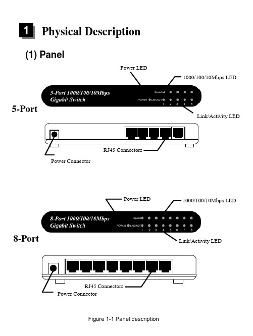
Physical Description(1) PanelPower LED1000/100/10Mbps LEDLink/Activity LEDPower Connector5-PortPower LEDLink/Activity LED8-Port1000/100/10Mbps LEDFigure 1-1 Panel description(2) LED5/8 Port Gigabit SwitchTable 1-1 LED descriptionInstallation1. Operating EnvironmentThis switching hub must be installed and operated within the limits of specified operating temperature (32-1310F) and humidity (10-95% Noncondensing). Do not place objects on top of the unit. Do not obstruct any vents at the sides of the unit. Do not position the unit near any heating source such as heater, radiator, or direct exposure to sun. Prevent entering of water and moisture into the unit. If necessary, use dehumidifier to reduce humidity.2. Connecting to network devicesThe RJ-45 ports on the switch support Auto-MDI/MDI-X function which allows using straight-through or cross-over type cables to connect this switch to workstation or hub.Connect one end of the network cable to the RJ-45 port on the rear panel, and connect the other end of the network cable to the RJ-45 port on the network device. Follow the same procedure to connect all the RJ-45 ports of the switch. The UTP network cables must comply with EIA/TIA 568 specifications and Category 5 standard for 1000Mbps data transmission. Maximum length, using UTP cable, between the switch and connected device is 100 meters (300ft). Once the network cable is connected to both ends and the attached network device is powered on, the green LNK/ACT LED should be lit.3. Connecting the poweradapter to the power connector on therear panel of the unit. Connect thepower adapter to the power outlet.The green Power LED on the frontpanel should be lit.Figure 2-1 Connect the power adapterTrouble-shooting1. Power LED is not litz Check if the power cord is properly connected to the external power adapter and the power outlet. Make sure the power jack is firmly plugged into the power socket of the switch.2. Link/Activity is not lit when connect to 1000/100Mbps devicez Check the power switch of the network device attached to the switch;make sure it is turned ON.z Check the network cable; make sure it is properly connected to the switch and the network device.z Check the network cable; make sure the UTP cables comply with EIA/TIA 568 and Category 5 specification.[!] Contact your dealer if problem persist.。
交换5
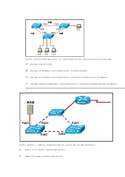
请参见图示。
该网络中所有交换机的MAC 表均为空。
而且,该网络中的交换机已禁用STP。
该网络中会如何处理主机PC1 所发送的广播帧?交换机SW1 会拦截广播并丢弃该帧。
交换机SW1 会将广播从除源端口之外的所有交换机端口转发出去。
这会在网络中造成无限循环。
交换机SW1 会将广播从除源端口之外的所有交换机端口转发出去。
而该网络中的所有主机则通过向主机PC1 发送单播帧来回应。
交换机SW1 会将该通信作为单播帧从除源端口之外的所有交换机端口转发出去。
而该网络中的所有主机则通过向交换机SW1 发送单播帧来回应请参见图示。
服务器发送了一个ARP 请求,询问其默认网关的MAC 地址。
如果未启用STP,则此ARP 请求的结果是什么?Router_1 会丢弃该广播并使用下一跳路由器的MAC 地址来回应。
Switch_A 会使用Router_1 的E0 接口的MAC 地址来回应。
Switch_A 和Switch_B 会将该消息持续泛洪到网络中。
该消息会在网络中反复传输,直到超出其TTL 为止。
在具有一个生成树实例的已收敛的网络中,将存在哪两项要素?(选择两项。
)每个网络有一个根桥所有非指定端口转发每个非根桥有一个根端口每个网段有多个指定端口每个网络有一个指定端口交换机使用哪两个条件来选择根桥?(选择两项。
)网桥的优先级交换速度端口数量基本MAC 地址交换机位置内存大小交换机通过哪两种方式使用BPDU 中的信息?(选择两项。
)用于在交换机之间协商中继链路用于设置冗余链路的双工模式用于确定到达根桥的最短路径用于通过在相连的交换机间共享桥接表来防止环路用于确定将哪些端口作为生成树的一部分转发帧下列哪两种说法正确描述了生成树拓扑中所用的BID?(选择两项。
)只有在下级BPDU 被发送出去后,它们才会被根桥发送出去。
它们包含网桥优先级和MAC 地址。
只有根桥会发送出BID。
它们被生成树拓扑中的交换机用来选举根桥。
具有最快处理器的交换机将具有最低的BID。
W5500中文数据手册_V1.1

2.3.1 写访问——VDM 模式 .................................................................. 19
2.3.2 读访问——VDM 模式 .................................................................. 22
5.4
功耗 Power Dissipation .................................................................... 62
5.5
交流特性 ..................................................................................... 62
W5500 数据手册版本 1.1 (2014 十一月)
5 / 67
插图清单
图 1W5500 引脚分布 ...............................................................................8 图 2 外部参考电阻 ................................................................................ 11 图 3 晶振参考电路 ................................................................................ 12 图 4 可变数据长度模式(SCSn 受主机控制) ................................................ 13 图 5 固定数据长度模式(SCSn 保持接地) ................................................... 13 图 6 SPI 模式 0&3 ................................................................................ 14 图 7 SPI 数据帧格式 .............................................................................. 15 图 8 在 VDM 模式下读 SPI 数据帧 .............................................................. 19 图 9 VDM 模式下,SIMR 寄存器写操作 ........................................................ 20 图 10 在 VDM 模式下,向 Socket1 的发送缓存区 0x0040 中写入 5 字节数据 ........... 21 图 11 在 VDM 模式下读 SPI 数据帧 ............................................................. 22 图 12 在 VDM 模式下读 S7_SR................................................................... 23 图 13 在 VDM 模式下,读取 Socket 3 接收缓存 0x0100 中的 5 字节数据 ................ 24 图 14 在 FDM 模式下,1 字节写访问 SPI 数据帧 ............................................. 26 图 15 在 FDM 模式下,2 字节写访问 SPI 数据帧 ............................................. 26 图 16 在 FDM 模式下,4 字节写访问 SPI 数据帧 ............................................. 26 图 17 在 FDM 模式下,1 字节读访问 SPI 数据帧 ............................................. 27 图 18 在 FDM 模式下,2 字节读访问 SPI 数据帧 ............................................. 27 图 19 在 FDM 模式下,4 字节读访问 SPI 数据帧 ............................................. 27 图 20 寄存器及内存构成 ......................................................................... 29 图 21INTLEVEL 时序 .............................................................................. 35 图 22 复位时钟 .................................................................................... 62 图 23 SPI 时钟 ..................................................................................... 63 图 24 变压器类型 ................................................................................. 65 图 25 封装描述 .................................................................................... 66
SW管路设计总结(周传孟总结)
SW管路设计总结
<针对SW2011>
FIRST
办公室产品点击solidworks routing
SECOND
为每一个零件添加“连接点”
(如何添加:
1,打开零件模型
2,菜单栏——routing——routing工具——生成连接点
3,选择圆柱的端面
4,选择管筒
5,在参数的直径一栏填写直径或者直接选择管筒
6,端头长度
7,最低直长度
8,注意同一根管路连接两个连接点时,两个连接点的直径和类型(管筒)必须一致
)
THIRD
“隐藏显示项目”按钮,选择显示“观阅步路点”
FOURTH
在装配图中,先择一个步路点,单击鼠标右键,开始步路
FIFTH
画空间直线
SIXTH
选择线路的最后一个步路点,单击鼠标右键,添加到线路
SEVENTH
线路中间所有拐角要圆角过渡,大多数会自动过渡,不自动过渡的,要自已生成圆角EIGHTH
生成管路
NINTH
对于柔性气管,方法同上
不同点在于:
1,管路连接要采用,两端直线,中间样条曲线
2,在直线与样条曲线连接处要采用相切的关系
3,相切要相对,如果是方向不是相要的方向,应左键点击相切关系,单击右键,选择“反转几何关系”
4,选中样条曲线,右键,显示曲率检查
5,如果样条曲线某些部份曲率过小,右键,插入样条曲线型值点。
通过拖动点来调整曲线的曲率。
- 1、下载文档前请自行甄别文档内容的完整性,平台不提供额外的编辑、内容补充、找答案等附加服务。
- 2、"仅部分预览"的文档,不可在线预览部分如存在完整性等问题,可反馈申请退款(可完整预览的文档不适用该条件!)。
- 3、如文档侵犯您的权益,请联系客服反馈,我们会尽快为您处理(人工客服工作时间:9:00-18:30)。
5.5
VLAN的创建与配置 VLAN的创建与配置
5.5.3 划分 划分VLAN端口 端口
1. VLAN端口的划分 VLAN端口的划分就是将指定的端口,划分指派到各 自所属的VLAN。 划分方法分为二步,第一步是选择要划分指派的端 口,第二步,使用switchport access vlan vlan-id 命令进行划分指派。
5.2
VLAN的分类 VLAN的分类 1. 静态VLAN 静态VLAN就是明确指定各端口所属VLAN的一种划分
方法。也称为基于端口的VLAN。 一个VLAN的端口可以是同一台交换机的任意端口, 也可分别来自不同的交换机端口。 2. 动态VLAN 动态VLAN是根据每个端口所连的计算机,动态设置 端口所属VLAN的划分方法。动态VLAN使用较少。
S3560(config-if)#ip address 192.168.2.1 255.255.255.0
S3560(config-if)#int vlan 30
S3560(config-if)#ip address 192.168.3.1 255.255.255.0
5.6
配置Trunk链路 配置Trunk链路 Trunk
5.6
配置Trunk链路 配置Trunk链路 Trunk
Trunk链路的配置方法 5.6.2 Trunk链路的配置方法 3. 配置Trunk链路允许通过的VLAN (2)相对指定方式 默认允许通过的VLAN号为1002-1005和VLAN 1。可在 此基础上增加或删除不允许通过的VLAN号。 指定不允许通过的VLAN,配置命令: switchport trunk allowed vlan remove vlanlist 增加允许通过的VLAN,配置命令: switchport trunk allowed vlan add vlanlist
5.6
配置Trunk链路 配置Trunk链路 Trunk
5.6.3 案例的配置实现 1. 配置接入层交换机 配置内容:创建和划分VLAN 10和VLAN 20,配置 Fa0/24为trunk端口。 2. 配置汇聚层交换机 配置内容:创建VLAN 10和VLAN 20,配置Fa0/24为 Trunk口,并配置VLAN子接口的IP地址。 3. 校验配置结果
5.5.2 创建 创建VLAN
1. VLAN的创建命令 命令:vlan vlan-id name vlan-name 若要创建编号为10的VLAN,则创建命令为vlan 10 另外,在创建VLAN时,还可给VLAN取一个标识名称。 例如,c3550(vlan)#vlan 10 name teachergroup 2. 配置实例 参见教材第171页。
5.6
配置Trunk链路 配置Trunk链路 Trunk
Trunk链路的配置方法 5.6.2 Trunk链路的配置方法 3. 配置Trunk链路允许通过的VLAN (1)绝对指定方式 switchport trunk allowed vlan vlanlist 若要允许所有VLAN通过,则配置命令为: switchport trunk allowed vlan all 若要允许vlan 1、vlan 10、vlan 20和vlan 30通过, 则命令为: switchport trunk allowed vlan 1,10,20,30
5.5
VLAN的创建与配置 VLAN的创建与配置
5.5.4 配置 配置VLAN子接口 子接口 3. VLAN子接口的配置命令 interface vlan vlan-id ip address address netmask ip helper-address dhcp-server-address no shutdown
5.5
VLAN的创建与配置 VLAN的创建与配置
5.5.3 划分 划分VLAN端口 端口
2. 配置实例 S3560#config t S3560(config)#int range fa0/2 – 14 S3560(config-if)#switchport access vlan 10 S3560(config-if)#int range fa0/15 – 20 S3560(config-if)#switchport access vlan 20 S3560(config-if)#int range fa0/21 – 24 S3560(config-if)#switchport access vlan 30
5.5
VLAN的创建与配置 VLAN的创建与配置
5.5.4 配置 配置VLAN子接口 子接口 4. 配置实例 S3560(config)#int vlan 10
S3560(config-if)#ip address 192.168.1.1 255.255.255.0
S3560(config-if)#int vlan 20
5.4
VTP管理域 VTP管理域
(1)Server模式 在对VLAN进行创建、修改和删除操作之后,VLAN配 置信息的变化,会自动传递到VTP域中处于Server或 Client模式的其它交换机,以实现对VLAN配置信息的 同步。 另外,处于Server模式的交换机,也可以接收同一 个VTP域中,其它交换机发送来的同步信息。
路由器的配置与管理》 《交换机/路由器的配置与管理》 交换机 路由器的配置与管理 (第2版) 版
作者:冯昊 黄治虎 清华大学出版社
第5章 配置虚拟局域网 章
5.1
虚拟局域网简介
虚拟局域网(Virtual Local Area Network,VLAN)是 将局域网从逻辑上划分为多个子网,实现虚拟工作组 的一种交换技术。 每一个VLAN就是一个子网,也称为一个网段。同一 个VLAN中的主机可相互通信,不同VLAN间的主机不能 直接相互通信。在配置了VLAN接口地址后,VLAN间可 实现相互通信。 利用VLAN,可隔离VLAN间的广播通信,缩小广播域。
5.4
VTP管理域 VTP管理域 2. VTP简介 VTP有Server、Clinet和Transparent三种工作模式,
这些工作模式决定了是否允许指定的交换机管理VLAN、 VTP如何传送和同步VLAN配置信息。 (1)Server模式 Server模式是交换机默认的工作模式,允许创建、 修改和删除本地VLAN数据库中的VLAN,并允许设置一 些对整个VTP域的配置参数。
5.7.2 单臂路由器的实现方法 3. 创建子接口 Cisco三层交换机和路由器支持创建子接口,即在一 个物理接口上,根据应用的需要,创建出多个逻辑子 接口,其创建方法是利用选择端口的命令,选择相应 的子接口即可。 例如,若物理接口为Fa0/1,则子接口分别为: Fa0/1.1、Fa0/1.2、Fa0/1.3…
5.3
Trunk链路与封装协议 Trunk链路与封装协议 Trunrunk链路与封装协议 2. Trunk链路的封装协议 由于Trunk链路是各VLAN流量的共同通道,必须有一
种方法来标识这些数据帧各属于哪一个VLAN。 VLAN封装协议用于对流经Trunk链路的数据帧进行打 标封装,附加上VLAN信息,以便交换机在接收到该数 据帧后,可通过VLAN标识,将数据帧转发到对应的 VLAN中去。 VLAN封装协议有国际标准的IEEE 802.1Q和Cisco厂 商标准的ISL。
5.4
VTP管理域 VTP管理域
(2)Client模式 处于该工作模式的交换机不能创建、修改和删除 VLAN。它主要通过VTP域内其它的交换机的VLAN配置信 息来同步和更新自己的VLAN配置。 (3)Transparent模式 可以创建、修改和删除VLAN,但对VLAN配置的变化, 不会传播给其它交换机,即仅对处于透明模式的交换 机自身有效。
5.3
Trunk链路与封装协议 Trunk链路与封装协议 (1)IEEE 802.1Q封装协议 所附加的VLAN识别信息,位于数据帧源MAC地址与类
型域之间,共4个字节。IEEE 802.1Q对数据帧的封装 过程如下图所示:
5.3
Trunk链路与封装协议 Trunk链路与封装协议 (2)ISL封装协议 仅Cisco的交换机和路由器支持。ISL采取在数据帧
5.3
Trunk链路与封装协议 Trunk链路与封装协议 1. Trunk链路 当一个VLAN的所属端口来自两个不同的交换机时,
这两台交换机的互联链路,必须采用Trunk链路。 Trunk链路允许不同VLAN的流量共同通过。因此链路 的流量压力较大,必须至少是100M的端口,才能做为 Trunk链路的端口。 Trunk链路如下图所示:
5.6.1 配置案例 参见教材第174页的例5.2。 Trunk链路的配置方法 5.6.2 Trunk链路的配置方法 1. 配置交换机端口的工作模式 交换机端口的工作模式有access和trunk两种,对于 Trunk链路两端的端口,工作模式必须设置为trunk。 配置命令:switchport mode access|trunk 2. 配置Trunk链路封装协议 switchport trunk encapsulation isl|dot1q
5.5
VLAN的创建与配置 VLAN的创建与配置
5.5.4 配置 配置VLAN子接口 子接口 1. VLAN子接口简介 每一个VLAN均有一个虚拟的VLAN子接口,通过给该 子接口配置接口IP地址,可实现VLAN间的相互通信。 配置接口地址后,由于各VLAN在同一台交换机上,它 们属于直连,可直接相互通信,不需要用户配置路由。
5.4
VTP管理域 VTP管理域
3. 创建 创建VTP管理域 管理域
(2)设置VTP模式 命令:vtp server|client|transparent (3)查看VTP信息 命令:show vtp status
5.5
VLAN的创建与配置 VLAN的创建与配置