AOTF404L中文资料
飞克 404E、406E、405、408和410激光距离计技术数据说明书

-10℃ to 60℃
Ingress protection
IP54
IP65
Drop test
1m
1m
Size
50 mm × 115mm × 29mm
52 mm × 116mm × 28mm
Weight
100g
110g
* Temperature for specified accuracy is 25°C ** Favorable conditions: white and diffuse reflection objects (white painted walls) ,low background illumination and moderate temperature *** Unfavorable conditions: objects with low or high reflectivity, high background illumination or the temperature is at the upper or lower limit of the specific temperature range
TECHNICAL DATA
Fluke 404E, 406E, 405, 408 and 410
Laser Distance Meter
Features and benefits
● Quickly measure distance, calculate area / volume / pythagoras ● Auto level and height ● Built to withstand rainy or dusty conditions : 1-meter drop tested
1.4404材质 标准
1.4404材质标准摘要:1.1.4404 材质的概述2.1.4404 材质的标准3.1.4404 材质的特点4.1.4404 材质的应用领域正文:1.1.4404 材质,又称为AISI 316 不锈钢,是一种具有良好耐腐蚀性能的奥氏体不锈钢。
其主要成分为碳(C)、硅(Si)、锰(Mn)、磷(P)、硫(S) 以及铬(Cr)、镍(Ni) 等元素,这些成分的恰当配比使得1.4404 材质在许多腐蚀环境中表现出优越的性能。
2.1.4404 材质的标准主要遵循美国不锈钢标准AISI 316,以及欧洲标准EN 10088-3。
在我国,1.4404 材质也得到了广泛应用,参照的标准有GB/T 1220-2007《不锈钢棒》和GB/T 3280-2012《不锈钢冷轧钢板和钢带》等。
3.1.4404 材质的特点主要表现在以下几个方面:- 良好的耐腐蚀性能:1.4404 材质中的铬含量达到了16%,使得它具有很好的耐腐蚀性能,特别是在弱腐蚀环境下,如海水、氯化物和其他化学介质中,表现出优越的耐蚀性。
- 耐高温性能:1.4404 材质具有较高的耐高温性能,其抗氧化性在高温下表现良好。
- 良好的焊接性能:1.4404 材质可以通过各种焊接方法进行焊接,具有良好的焊接性能。
4.1.4404 材质广泛应用于以下领域:- 食品工业:1.4404 材质符合食品安全标准,常用于制作食品机械、厨房用具等。
- 制药工业:1.4404 材质具有良好的耐腐蚀性能,在制药设备、管道等方面有着广泛应用。
- 化工设备:1.4404 材质在各种腐蚀性介质中表现出优越的性能,因此被广泛应用于化工设备制造。
- 建筑装饰:1.4404 材质外观美观,常用于制作豪华建筑的内外装饰材料。
F404涡轮风扇发动机
F404涡轮风扇发动机F404是由通用电气开发的静推力10,500-19,000磅(85kN)级的带加力涡轮风扇发动机,同系列发动机还包括F412、RM12,该系列由通用电气航空系统公司生产,合作伙伴沃尔沃宇航公司生产RM12型。
F404的发展型包括加大的推力的F414和实验型民用G36桨扇发动机。
发展历史通用电气在F-15“鹰”战斗机和轻型战斗机项目(YF-16获胜)中输给普惠公司的F-100发动机之后不久,便基于诺斯罗普YF-17用的YJ101发动机发展出了F404发动机,以装备F/A-18“大黄蜂”。
为加强燃油经济性将涵道比由0.20加大到0.34,把改进重点放在可靠性及降低成本上而不是性能上。
通用电气分析了“油门剖面”,发现飞行踩油门远比工程师先前想象的要频繁,给发动机以过大的压力。
通用电气还使F404避免压气机失速及其它发动机故障,将对控制输入作出迅速的反应,因为从螺旋桨飞机转到喷气式飞机的飞行员经常抱怨早期涡轮发动机对改变推力没有反应。
通用电气执行官Frederick A. Larson 和 Paul Setts给新发动机定下的目标是比F-4用的GE-J79发动机小,但推力要更大,并比F-16使用的普惠F100发动机成本低一半。
由于风扇设计使气流可以顺畅的进入压缩机,所以即使是高仰角,F404可以有效的防止压气机失速。
其平均大修时间1000飞行小时,飞行寿命6500小时。
它可以对控制命令作出迅速的反应,可以在4秒内从空转达到全力加速。
发动机集成了飞行环境监控系统,该系统用于关键故障和保障部件寿命。
通用电气基于F101和F404的技术为空军发展了F110发动机用于替换F-16和F15所使用的F100发动机。
通用电气研发的加大推力的F404-GE-402发动机用于装备出口瑞士的F/A-18。
科威特的“大黄蜂”也采用了该型发动机。
最终美军后来的“大黄蜂”C型和D型也采用了该发动机。
RM12该型为沃尔沃宇航公司改型的F404,提高了性能增强了抗鸟撞能力并为单发使用而提高了安全标准。
VLF4012AT-4R7M1R1;VLF4012AT-100MR79;VLF4012AT-3R3M1R3;VLF4012AT-2R2M1R5;中文规格书,Datasheet资料

Inductance tolerance(%) ±30 ±20 ±20 ±20 ±20 ±20 ±20
Test frequency (kHz) 100 100 100 100 100 100 100
DC resistance( ) max. 0.054 0.1 0.15 0.2 0.31 0.46 1.20 typ. 0.047 0.091 0.13 0.1R7
2.8±0.2
1.4max. Dimensions in mm
RECOMMENDED PC BOARD PATTERN
1.2 2.1 3.4 Dimensions in mm
Inductance [at 1/2 Idc1]3 (µH) 1 2.2 3.3 4.7 6.8 10 22
• All specifications are subject to change without notice.
/
001-04 / 20120310 / e531_vlf
(3/17)
Inductors for Power Circuits Wound/STD • Magnetic Shielded
Part No. VLF3014AT-1R0N1R7 VLF3014AT-2R2M1R2 VLF3014AT-3R3M1R0 VLF3014AT-4R7MR90 VLF3014AT-6R8MR72 VLF3014AT-100MR59 VLF3014AT-220MR37
1
SHAPES AND DIMENSIONS
VLF-MT Series VLF302510MT
With the VLF302510MT Series, a DC to DC converter with topclass voltage conversion efficiency for similar size products was achieved by optimizing the magnetic material and configuration. These products are optimal for use as choke coils in switching power supplies such as those in mobile devices requiring spacesaving design. FEATURES • Miniature size Mount area: 3.02.5mm Low profile: 1.0mm max. height • Generic use for portable DC to DC converter line. • High magnetic shield construction should actualize high resolution for EMC protection. • The products contain no lead and also support lead-free soldering. • The products is halogen-free. • It is a product conforming to RoHS directive. APPLICATIONS Smartphones, cellular phones, DSCs, DVCs, HDDs, LCD displays, compact power supply modules, etc. SHAPES AND DIMENSIONS
LS404中文资料

LS404
HIGH PERFORMANCE QUAD OPERATIONAL AMPLI SPLIT SUPPLY OPERATION LOW POWER CONSUMPTION SHORT CIRCUIT PROTECTION LOW DISTORTION, LOW NOISE HIGH GAIN-BANDWIDTH PRODUCT HIGH CHANNEL SEPARATION
Inches Typ. Max. 0.065 0.020 0.010 0.787 0.335 0.100 0.600 0.280 0.201 0.130 0.100
11/12
元器件交易网
LS404
PACKAGE MECHANICAL DATA 14 PINS - PLASTIC MICROPACKAGE (SO)
8 10 18
15
10 12 20
THD
Total Harmonic Distortion
±Vopp Vopp SR CMR SVR
Output Voltage Swing Large Signal Voltage Swing Slew Rate Common Mode Rejection Ratio Supply Voltage Rejection Ratio
Information furnished is believed to be accurate and reliable. However, SGS-THOMSON Microelectronics assumes no responsibility for the consequences of use of such information nor for any infringement of patents or other rights of third parties which may result from its use. No license is granted by implication or otherwise under any patent or patent rights of SGS-THOMSON Microelectronics. Specifications mentioned in this publication are subject to change without noti ce. This publication supersedes and replaces all information previously supplied. SGS-THOMSON Microelectronics products are not authorized for use as critical components in life support devices or systems without express written approval of SGS-THOMSON Microelectronics. © 1997 SGS-THOMSON Microelectronics – Printed in Italy – All Rights Reserved SGS-THOMSON Microelectronics GROUP OF COMPANIES Australia - Brazil - Canada - China - France - Germany - Italy - Japan - Korea - Malaysia - Malta - Morocco The Netherlands - Singapore - Spain - Sweden - Switzerland - Taiwan - Thailand - United Kingdom - U.S.A.
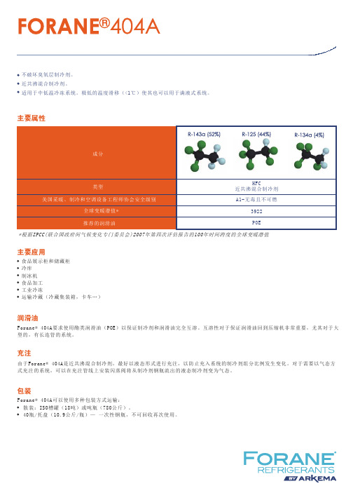
Forane 404A说明书
Forane® 404A可以使用多种包装方式运输:散装:ISO槽罐(18吨)或吨瓶(780公斤)。
40瓶/托盘(10.9公斤/瓶)— 一次性钢瓶,不可回收再次使用。
主要属性主要应用润滑油包装充注*根据IPCC(联合国政府间气候变化专门委员会)2007年第四次评估报告的100年时间跨度的全球变暖潜值HFC近共沸混合制冷剂不破坏臭氧层制冷剂。
近共沸混合制冷剂。
适用于中低温冷冻系统。
极低的温度滑移(<1℃)使其也可以用于满液式系统。
A1-无毒且不可燃3922POEForane® 404A要求使用酯类润滑油(POE)以保证制冷剂和润滑油完全互溶。
互溶性对于保证润滑油回到压缩机非常重要,尤其对于大型的,有长连管的系统。
食品展示柜和储藏柜冷库制冰机食品加工工业冷冻运输冷藏(冷藏集装箱,卡车…)由于Forane® 404A是近共沸混合制冷剂,最好以液态形式进行充注,以防止充入系统的制冷剂组分比例发生变化。
对于需要以气态方式充注的系统,可以在充注管线上安装闪蒸阀将从制冷剂钢瓶流出的液态制冷剂变为气态。
热物性参数下表数据基于NIST REFPROP数据库生成(NIST标准数据库23,9.0版,2010)此处包含的陈述、技术信息和建议至本公布日期均被视为准确信息。
由于本文所涉及的产品和信息的使用条件和方法是我们无法控制的,阿科玛明确表示不对由产品的使用及对以上信息的依赖所产生的任何及所有后果承担责任;对本文中描述的产品或提供的信息相对于某一特定用途的适应性、适销性均为做出任何明示或暗示的保证。
本文所提供的信息仅与指定的产品有关,且当这种产品与其他材料组合使用或用于任何过程中时,这些信息可能并不适用。
用户应在商业化之前彻底测试所有装置。
此处包含的任何内容均不构成对使用任何专利的许可,也不应该被解释为对任何专利权的侵犯,建议用户采取适当步骤以确保产品的任何建议用途均不会导致专利侵权。
AFD4040流量传感器说明书
传感器与控制器ASAIR奥松电子操作说明流量传感器处理开关必须按照国家或地方有关电气/电子设备的规定正确处理。
开关不能与家庭垃圾一起处理!安全指令安全说明旨在保护用户免受危险情况和/或防止材料损坏。
在操作说明书中,潜在风险的严重性可以用以下信号词来表示:!警告指可识别的危险。
不遵守可能导致致命的伤害,并破坏设备或工厂部件。
!谨慎指的是一种危险。
不遵守可能会对开关和/或工厂造成轻微伤害和物质损害。
重要的指对用户至关重要的信息。
!危险指用户面临的迫在眉睫的危险。
不遵守可能导致致命的伤害。
◇流量范围∶5~40L/min◇重复性:<2.0%◇压力等级:10bar(最大压力16bar)◇介质温度:-20~100℃螺纹型:G 1/2◇数字显示:无◇线性化:5点流量线性曲线◇精度:<±3.0%F.S(流量)◇接液材质:Pom/SUS304(不锈钢)◇过程连接:◇环境温度:-10~65℃◇供电电源:18~28VDC◇信号输出:三线制4~20mA,与流量成线性关系AFD4040图1.AFD4040(单位:mm)电源指示灯流量指示灯AFD4040接线图序号针脚定义1电源正2NC3电源负4流量模拟量流量=(额Max −额Min )∗(−4)/(−)+额Min安装安全说明旨在保护用户免受危险情况和/或防止材料损坏。
在操作说明书中,潜在风险的严重性可以用以下信号词来表示:配管方法:对产品配管时,请用扳手与配管部一体的金属部位(管路配件)进行配管。
若在其他的部位使用扳手,可能会导致流量开关破损。
特别是不能再M12连接器上使用扳手。
否则可能会导致连接器部破损安装配管:请不要使密封带混入管内。
配管连接:请不要因松弛而导致液体泄漏。
若超出紧固扭力范围拧紧,可能会导致开关损坏。
如果在不足规定紧固扭力的情况下组装,可能会使连接螺纹部松动。
!谨慎在运输过程中必须避免震动和剧烈震动。
即使开关外壳没有损坏,内部部件也可能损坏并引起故障。
F404中文资料

Flex 404 Four-Zone FACP CS-2404 09/01/06Page 1 of2DescriptionThe Gamewell Flex 404 Fire Alarm Control Panel brings the latest in mi-croprocessor technology to conven-tional fire controls. The Flex 404 is compatible with the new i³ ™ smoke detectors from System Sensor, and provides advanced features including drift compensation, maintenance alert,and freeze warning. Automatic syn-chronization of audio/visual devices is provided, selectable for three manufac-turers’ protocols. The NAC protocol in-cludes the ability, using a single pair of wires, to silence audible deviceswhile strobes continue to flash.The Flex 404 is also compatible with conventional input devices such as two-and four-wire smoke detectors, pull stations, waterflow devices, tamper switches and other normally-open contact devices.OperationThe activation of a compatible smoke detector or any normally-open fire alarm initiating device will: activate audible and visual signaling devices, illuminate an indicating LED, sound the piezo sounder at the FACP , activate the FACP alarm relay, and operate an optional module which notifies a remote station or initiates an auxiliary control function.i³™ Technology Features•Drift compensation automatically adjusts detector sensitivity and increases resistance to false alarms caused by dust accumulation.•The maintenance alert LEDs (per zone) warn of excessive dirt accumulation,preventing false alarms.•Detector sensitivity is automatically measured. The twice-yearly test require-ments of NFPA 72 (7-3.2.1) are met without using a ladder or test meter.•The wireless handheld sensitivity meter eliminates the need for voltmeters,magnets, or a physical connection to the detector. The reader displays sensi-tivity in terms of percent-per-foot obscuration and provides text status indica-tion.•The supervisory LED (per zone) provides a warning if a detector senses tem-peratures approaching freezing.•Special test protocol and LED indication allow a quick test of all detectors —without a ladder.•Electronic heat-sensing element provides thermal detection in addition to pho-toelectronic smoke detection.Features•Four Style B (Class B) Initiating Device Circuits (IDCs); two Style Y (Class B) Notification Appliance Circuits (NACs); optional module (P/N CAC-4) converts 4 IDCs and two NACs to Class A. 24 VDC.•NAC synchronization features:–Provides synchronization of standard ANSI audible signals as required by NFPA 72(3-8.4.1.2.3).–Provides synchronization of ADA compliant strobes per NFPA 72 (4-4.4.1).–Selectable for System Sensor, Cooper-Wheelock,& Gentex protocols.–Selective Silence feature allows manual silencing of horns while strobes continue to flash on the same NAC.•Silent or A udible Walk Test operation mode commanded from the front keypad, with automatic return to normal after one hour of inactivity.•Alarm verification selectable per zone.•Each zone may be programmed for supervisory or fire; each zone has separate red and yellow LEDs.•Disable switches provided for each zone.•NACs programmable for: Silence Inhibit, Auto Silence, Strobe Synchronization, Selective Silence (horn/strobe mute), Temporal orSteady signal, Silenceable or Nonsilenceable.•Form-C Alarm, Trouble, and Supervisory relays.• 3.0 A (6.0 A with optional second transformer)total usable current.•Piezo sounder for alarm, trouble, supervisory,and maintenance.•Control buttons: ACK (Acknowledge), A larm Silence, Reset, Walktest, Zone Enable/Disable (one per zone).•LED indicators: Fire Alarm (one per zone),Supervisory (one per zone), Trouble (one per zone), Maintenance (one per zone), AC Power, NAC Disable, Zone Disable, NAC Fault, System Trouble, Power Trouble,Walktest, Alarm Silence, Earth Fault (on circuit board), Battery Fault (on circuit board),Charger Fault (on circuit board).•Optional dress panel (P/N DP-FLEX ).•Optional modules: plug-in transmitter module (P/N 4XTMF ); plug-in zone relay module (P/N 4XZMF ); transmitter module (P/N4XLMF ) for SAN-404 remote LED annuncia-tor.ListingsListings and approvals below apply to the basic Flex 404 panel. In some cases, certain modules may not be listed by certain approval agencies, or listing may be in process.Consult factory for latest listing status.•UL Listed: file S521.•CSFM approved: file 7165-1288:180.•MEA approved: file 366-04-E.Flex 404Four-Zone Fire Alarm Control Panelg 2404p h 1.j pgFlex 404 Four-Zone FACP CS-2404 09/01/06Page 2 of 2Specifications and wiring information are provided for information only and are believed to be accurate. Gamewell-FCI assumes no responsibility for their use.Data and design are subject to change without notice. Installation and wiringinstructions shipped with the product shall always be used for actual installation. For more information, contact Gamewell-FCI. Gamewell-FCI 12 Clintonville Road Northford, CT 06472-1610Phone: 203-484-7161Fax: A Honeywell Company© 2006 Gamewell-FCIBackbox MountingThe cabinet can be surface-mounted. The door is removable during installation by opening and lifting it off the hinges. The cabinet mounts using two key slots at the top of the backbox and two additional 0.250" diameter holes at the bottom.Ordering InformationF404Four-zone conventional FACP .XRM-24120 VAC, 100 VA transformer, expands NAC power from 3.0to 5.0 Amps.CAC-4Class A converter module. Used to convert Style B (Class B) IDC to Style D (Class A) and Style Y (Class B) NAC to Style Z (Class A). The module connects to J1 on the Flex 404 circuit board.4XTMF Transmitter module.4XLMF LED interface module, supports SAN-404.4XZMF Zone relay module.411UDFour-input (channel) 411UD dual-line Digital Alarm Commu-nicator/Transmitters, which can be used as slave communi-cators with Flex 404.PRO-411Programmer used with 411UD.SAN-404Remote annunciator (RZA-4XF), mounts in a single-gang box.BB-17F Battery box, required to house two batteries greater than 7AH, to a maximum of 18 AH.DP-FLEX Dress panel.TR-1-R Trim ring for semi-flush mounting.52194Flex 404 Installation and Maintenance Manual.i³™ is a trademark and Gamewell® is a registered trademark of Honeywell International Inc.。
衬氟安全阀
A42F46弹簧全启封闭式安全阀型适用于工作温度≤130℃有腐蚀性介质的设备或管路上,作为超压保护装置
A42F46衬氟安全阀适用于:化工、氯气、有毒介质的管线系统
衬氟安全阀是本高公司根据国外先进技术消化吸收研制成功的最新化工行业领域专用安全阀,衬氟安全阀主要用于氯碱化工、液氯、盐酸等高危腐蚀性介质受压设备、压力容器及管路上的自动压力释放装置。
在关键部分采用全衬四氟(PFA\F46)材质,可耐液氯、盐酸、强腐蚀性等介质,阀体进行内衬四氟增加了耐腐蚀性能。
耐腐蚀性能:阀体内部、阀芯、阀瓣、阀杆均进行全衬2.5~3mm厚的PFA、F46,能耐液氯,盐酸等腐蚀性介质。
衬氟安全阀适用温度为:130℃
衬氟安全阀的其他型号有:A42F46-16C、A42F46-25C、A42F46-40C、A42F46-16P、A42F46-25P、A42F46-40P
阀体材质有:WCB、304、316、316L
上海本高阀门有限公司:021-5756647615221777155。
UFR404资料
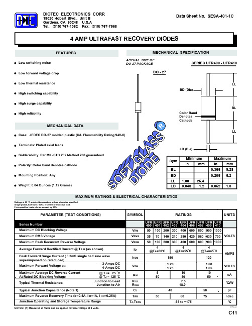
SYMBOL
RATINGS
UFR UFR UFR UFR UFR UFR UFR UFR UFR 400 401 402 403 404 406 408 409 410
Sym
Polarity: Color band denotes cathode
Minimum In mm
BL
Mounting Position: Any Weight: 0.04 Ounces (1.12 Grams)
Maximum In mm 9.28 0. 1.00 0.048 25.4 1.2
0.052
MAXIMUM RATINGS & ELECTRICAL CHARACTERISTICS
Ratings at 25 °C ambient temperature unless otherwise specified. Single phase, half wave, 60Hz, resistive or inductive load. For capacitive loads, derate current by 20%.
800 900 1000 4 @TA=45o C 120 1.60 1.65 10 50 VOLTS µA °C/W 50 75 pF nSec °C
4.97fsesa4
4 @TA=80oC
AMPS
@ TJ = 25 C @ TJ = 125 oC Junction to Lead Junction to Air
MECHANICAL DATA
LL
Case: JEDEC DO-27 molded plastic (U/L Flammability Rating 94V-0) Terminals: Plated axial leads LD (Dia) Solderability: Per MIL-STD 202 Method 208 guaranteed
LM4041中文资料
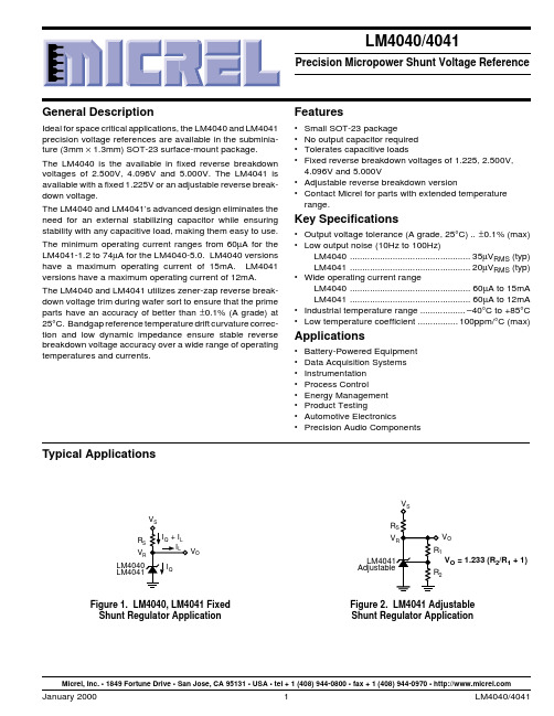
Typical ApplicationsV O V R V V OFigure 2. LM4041 Adjustable Shunt Regulator ApplicationFigure 1. LM4040, LM4041 Fixed Shunt Regulator Application V O = 1.233 (R 2/R 1 + 1)Micrel, Inc. • 1849 Fortune Drive • San Jose, CA 95131 • USA • tel + 1 (408) 944-0800 • fax + 1 (408) 944-0970 • Part Number *Voltage Accuracy,Temp. Coefficient LM4041AIM3-1.2 1.225V ±0.1%, 100ppm/°C LM4041BIM3-1.2 1.225V ±0.2%, 100ppm/°C LM4041CIM3-1.2 1.225V ±0.5%, 100ppm/°C LM4041DIM3-1.2 1.225V ±1.0%, 150ppm/°C LM4041CIM3-ADJ 1.24V to 10V ±0.5%, 100ppm/°C LM4041DIM3-ADJ1.24V to 10V±1.0%, 150ppm/°CPin Configuration–FB +Adjustable Version SOT-23 (M3) PackageTop ViewFixed Version SOT-23 (M3) PackageTop View +–Pin 3 must float or be connected to pin 2.Part Number *Voltage Accuracy,Temp. Coefficient LM4040AIM3-2.5 2.500V ±0.1%, 100ppm/°C LM4040BIM3-2.5 2.500V ±0.2%, 100ppm/°C LM4040CIM3-2.5 2.500V ±0.5%, 100ppm/°C LM4040DIM3-2.5 2.500V ±1.0%, 150ppm/°C LM4040AIM3-4.1 4.096V ±0.1%, 100ppm/°C LM4040BIM3-4.1 4.096V ±0.2%, 100ppm/°C LM4040CIM3-4.1 4.096V ±0.5%, 100ppm/°C LM4040DIM3-4.1 4.096V ±1.0%, 150ppm/°C LM4040AIM3-5.0 5.000V ±0.1%, 100ppm/°C LM4040BIM3-5.0 5.000V ±0.2%, 100ppm/°C LM4040CIM3-5.0 5.000V ±0.5%, 100ppm/°C LM4040DIM3-5.05.000V±1.0%, 150ppm/°CExample Field Code _ _ A3rd CharacterA = ±0.1%B = ±0.2%C = ±0.5%D = ±1.0%Example FieldCode_ 2 _2nd Character 1 = 1.225V2 = 2.500V 4 = 4.096V 5 = 5.000V A = AdjustableExample: R2C represents Reference, 2.500V,±0.5% (LM4040CIM3-2.5)Note: If 3rd character is omitted, container will indicate tolerance.SOT -23 Package MarkingsExample Field Code R _ _1st CharacterR = ReferenceOrdering InformationAbsolute Maximum RatingsReverse Current.........................................................20mA Forward Current.........................................................10mA Maximum Output VoltageLM4041-Adjustable ...................................................15V Power Dissipation at T A = 25°C (Note 2)................306mW Storage Temperature...............................–65°C to +150°C Lead TemperatureVapor phase (60 seconds)..............................+215°C Infrared (15 seconds)......................................+220°C ESD SusceptibilityHuman Body Model (Note 3).................................2kV Machine Model (Note 3).. (200V)Operating Ratings (Notes 1 and 2)Temperature Range(T MIN ≤ T A ≤ T MAX )..........................–40°C ≤ T A ≤ +85°C Reverse CurrentLM4040-2.5..........................................60µA to 15mA LM4040-4.1..........................................68µA to 15mA LM4040-5.0..........................................74µA to 15mA LM4041-1.2..........................................60µA to 12mA LM4041-ADJ ........................................60µA to 12mA Output Voltage RangeLM4041-ADJ ..........................................1.24V to 10V+Functional Diagram LM4040, LM4041 Fixed Functional Diagram LM4041 Adjustable+LM4040-2.5 Electrical CharacteristicsBoldface limits apply for T A = T J = T MIN to T MAX; all other limits T A = T J = 25°C. The grades A, B, C, and D designate initial Reverse Breakdown Voltage tolerance of ±0.1%, ±0.2%, ±0.5%, and ±1.0 respectively.LM4040AIM3LM4040BIM3LM4040CIM3Symbol Parameter Conditions Typical Units(Note 4)Limits Limits Limits(Limit)(Note 5)(Note 5)(Note 5)V R Reverse Breakdown Voltage I R = 100µA 2.500VReverse Breakdown Voltage I R = 100µA±2.5±5.0±12mV (max) Tolerance±19±21±29mV (max) I RMIN Minimum Operating Current45µA606060µA (max)656565µA (max)∆V R/∆T Average Reverse Breakdown I R = 10mA20ppm/°C Voltage Temperature I R = 1mA151********ppm/°C (max) Coefficient I R = 100µA15ppm/°C (max)∆V R/∆I R Reverse Breakdown Voltage I RMIN≤ I R 1mA0.3mV Change with Operating0.80.80.8mV (max) Current Change 1.0 1.0 1.0mV (max)1mA ≤ I R 15mA 2.5mV0.60.60.6mV (max)8.08.08.0mV (max)Z R Reverse Dynamic Impedance I R = 1mA, f = 120Hz0.3ΩI AC = 0.1 I R0.80.80.9Ω (max)e N Wideband Noise I R = 100µA10Hz ≤ f ≤ 10kHz35µV RMS∆V R Reverse Breakdown Voltage t = 1000hrsLong Term Stability T = 25°C ±0.1°C120ppmI R = 100µALM4040DIM3Symbol Parameter Conditions Typical Units(Note 4)Limits(Limit)(Note 5)V R Reverse Breakdown Voltage I R = 100µA 2.500VReverse Breakdown Voltage I R = 100µA±25mV (max) Tolerance±49mV (max) I RMIN Minimum Operating Current45µA65µA (max)70µA (max)∆V R/∆T Average Reverse Breakdown I R = 10mA20ppm/°C Voltage Temperature I R = 1mA15150ppm/°C (max) Coefficient I R = 100µA15ppm/°C (max)∆V R/∆I R Reverse Breakdown Voltage I RMIN≤ I R 1mA0.3mV Change with Operating 1.0mV (max) Current Change 1.2mV (max)1mA ≤ I R 15mA 2.5mV8.0mV (max)10.0mV (max)Z R Reverse Dynamic Impedance I R = 1mA, f = 120Hz0.3ΩI AC = 0.1 I R 1.1Ω (max)e N Wideband Noise I R = 100µA10Hz ≤ f ≤ 10kHz35µV RMS∆V R Reverse Breakdown Voltage t = 1000hrsLong Term Stability T = 25°C ±0.1°C120ppmI R = 100µALM4040-4.1 Electrical CharacteristicsBoldface limits apply for T A = T J = T MIN to T MAX; all other limits T A = T J = 25°C. The grades A, B, C, and D designate initial Reverse Breakdown Voltage tolerance of ±0.1%, ±0.2%, ±0.5%, and ± 1.0% respectively.LM4040AIM3LM4040BIM3Symbol Parameter Conditions Typical Units(Note 4)Limits Limits(Limit)(Note 5)(Note 5)V R Reverse Breakdown Voltage I R = 100µA 4.096VReverse Breakdown Voltage I R = 100µA±4.1±8.2mV (max) Tolerance±31±35mV (max) I RMIN Minimum Operating Current50µA6868µA (max)7373µA (max)∆V R/∆T Average Reverse Breakdown I R = 10mA30ppm/°C Voltage Temperature I R = 1mA20100100ppm/°C (max) Coefficient I R = 100µA20ppm/°C (max)∆V R/∆I R Reverse Breakdown Voltage I RMIN≤ I R 1mA0.5mV Change with Operating0.90.9mV (max) Current Change 1.2 1.2mV (max)1mA ≤ I R 15mA 3.5mV7.07.0mV (max)10.010.0mV (max)Z R Reverse Dynamic Impedance I R = 1mA, f = 120Hz0.5ΩI AC = 0.1 I R 1.0 1.0Ω (max)e N Wideband Noise I R = 100µA10Hz ≤ f ≤ 10kHz80µV RMS∆V R Reverse Breakdown Voltage t = 1000hrsLong Term Stability T = 25°C ±0.1°C120ppmI R = 100µALM4040CIM3LM4040DIM3Symbol Parameter Conditions Typical Units(Note 4)Limits Limits(Limits)(Note 5)(Note 5)V R Reverse Breakdown Voltage I R = 100µA 4.096VReverse Breakdown Voltage I R = 100µA±20±41mV (max) Tolerance±47±81mV (max) I RMIN Minimum Operating Current50µA6873µA (max)7378µA (max)∆V R/∆T Average Reverse Breakdown I R = 10mA30ppm/°C Voltage Temperature I R = 1mA20100150ppm/°C (max) Coefficient I R = 100µA20ppm/°C (max)∆V R/∆I R Reverse Breakdown Voltage I RMIN≤ I R 1mA0.5mV Change with Operating0.9 1.2mV (max) Current Change 1.2 1.5mV (max)1mA ≤ I R 15mA 3.0mV7.09.0mV (max)10.013.0mV (max)Z R Reverse Dynamic Impedance I R = 1mA, f = 120Hz0.5ΩI AC = 0.1 I R 1.0 1.3Ω (max)e N Wideband Noise I R = 100µA10Hz ≤ f ≤ 10kHz80µV RMS∆V R Reverse Breakdown Voltage t = 1000hrsLong Term Stability T = 25°C ±0.1°C120ppmI R = 100µALM4040-5.0 Electrical CharacteristicsBoldface limits apply for T A = T J = T MIN to T MAX; all other limits T A = T J = 25°C. The grades A, B, C, and D designate initial Reverse Breakdown Voltage tolerance of ±0.1%, ±0.2%, ±0.5%, and ± 1.0% respectively.LM4040AIM3LM4040BIM3Symbol Parameter Conditions Typical Units(Note 4)Limits Limits(Limit)(Note 5)(Note 5)V R Reverse Breakdown Voltage I R = 100µA 5.000VReverse Breakdown Voltage I R = 100µA±5.0±10mV (max) Tolerance±38±43mV (max) I RMIN Minimum Operating Current54µA7474µA (max)8080µA (max)∆V R/∆T Average Reverse Breakdown I R = 10mA30ppm/°C Voltage Temperature I R = 1mA20100100ppm/°C (max) Coefficient I R = 100µA20ppm/°C (max)∆V R/∆I R Reverse Breakdown Voltage I RMIN≤ I R 1mA0.5mV Change with Operating 1.0 1.0mV (max) Current Change 1.4 1.4mV (max)1mA ≤ I R 15mA 3.5mV8.08.0mV (max)12.012.0mV (max)Z R Reverse Dynamic Impedance I R = 1mA, f = 120Hz0.5ΩI AC = 0.1 I R 1.1 1.1Ω (max)e N Wideband Noise I R = 100µA10Hz ≤ f ≤ 10kHz80µV RMS∆V R Reverse Breakdown Voltage t = 1000hrsLong Term Stability T = 25°C ±0.1°C120ppmI R = 100µALM4040CIM3LM4040DIM3Symbol Parameter Conditions Typical Units(Note 4)Limits Limits(Limits)(Note 5)(Note 5)V R Reverse Breakdown Voltage I R = 100µA 5.000VReverse Breakdown Voltage I R = 100µA±25±50mV (max) Tolerance±58±99mV (max) I RMIN Minimum Operating Current54µA7479µA (max)8085µA (max)∆V R/∆T Average Reverse Breakdown I R = 10mA30ppm/°C Voltage Temperature I R = 1mA20100150ppm/°C (max) Coefficient I R = 100µA20ppm/°C (max)∆V R/∆I R Reverse Breakdown Voltage I RMIN≤ I R 1mA0.5mV Change with Operating 1.0 1.3mV (max) Current Change 1.3 1.8mV (max)1mA ≤ I R 15mA 3.5mV8.010.0mV (max)12.015.0mV (max)Z R Reverse Dynamic Impedance I R = 1mA, f = 120Hz0.5ΩI AC = 0.1 I R 1.1 1.5Ω (max)e N Wideband Noise I R = 100µA10Hz ≤ f ≤ 10kHz80µV RMS∆V R Reverse Breakdown Voltage t = 1000hrsLong Term Stability T = 25°C ±0.1°C120ppmI R = 100µALM4040 Typical CharacteristicsTest CircuitVLM4041-1.2 Electrical CharacteristicsBoldface limits apply for T A = T J = T MIN to T MAX; all other limits T A = T J = 25°C. The grades A, B, C, and D designate initial Reverse Breakdown Voltage tolerance of ±0.1%, ±0.2%, ±0.5%, and ± 1.0%, respectively.LM4041AIM3LM4041BIM3LM4041CIM3Symbol Parameter Conditions Typical Units(Note 4)Limits Limits Limits(Limit)(Note 5)(Note 5)(Note 5)V R Reverse Breakdown Voltage I R = 100µA 1.225V Reverse Breakdown Voltage I R = 100µA±1.2±2.4±6mV (max) Tolerance±9.2±10.4±14mV (max) I RMIN Minimum Operating Current45µA606060µA (max)656565µA (max)∆V R/∆T Average Reverse Breakdown I R = 10mA20ppm/°C Voltage Temperature I R = 1mA15±100±100±100ppm/°C (max)Coefficient I R = 100µA15ppm/°C (max)∆V R/∆I R Reverse Breakdown Voltage I RMIN≤ I R 1mA0.7mV Change with Operating 1.5 1.5 1.5mV (max) Current Change 2.0 2.0 2.0mV (max)1mA ≤ I R 15mA 4.0mV6.0 6.0 6.0mV (max)8.08.08.0mV (max) Z R Reverse Dynamic Impedance I R = 1mA, f = 120Hz0.5ΩI AC = 0.1 I R 1.5 1.5 1.5Ω (max)e N Wideband Noise I R = 100µA10Hz ≤ f ≤ 10kHz20µV RMS∆V R Reverse Breakdown Voltage t = 1000hrsLong Term Stability T = 25°C ±0.1°C120ppmI R = 100µALM4041DIM3LM4041EIM3Symbol Parameter Conditions Typical Units(Note 4)Limits Limits(Limit)(Note 5)(Note 5)V R Reverse Breakdown Voltage I R = 100µA 1.225V Reverse Breakdown Voltage I R = 100µA±12±25mV (max) Tolerance±24±36mV (max) I RMIN Minimum Operating Current45µA6565µA (max)7070µA (max)∆V R/∆T Average Reverse Breakdown I R = 10mA20ppm/°C Voltage Temperature I R = 1mA15±150±150ppm/°C (max) Coefficient I R = 100µA15ppm/°C (max)∆V R/∆I R Reverse Breakdown Voltage I RMIN≤ I R 1mA0.3mV Change with Operating 2.0 2.0mV (max) Current Change 2.5 2.5mV (max)1mA ≤ I R 15mA 2.5mV8.08.0mV (max)10.010.0mV (max) Z R Reverse Dynamic Impedance I R = 1mA, f = 120Hz0.3ΩI AC = 0.1 I R 2.0 2.0Ω (max)e N Wideband Noise I R = 100µA10Hz ≤ f ≤ 10kHz35µV RMS∆V R Reverse Breakdown Voltage t = 1000hrsLong Term Stability T = 25°C ±0.1°C120ppmI R = 100µALM4041-Adjustable Electrical CharacteristicsBoldface limits apply for T A = T J = T MIN to T MAX; all other limits T J = 25°C unless otherwise specified (SOT-23, see Note 7),I RMIN≤ I R < 12mA, V REF≤ V OUT≤ 10V. The grades C and D designate initial Reverse Breakdown Voltage tolerance of ±0.5% and±1%, respectively for V OUT = 5V.LM4041CIM3LM4041DIM3Symbol Parameter Conditions Typical Units(Note 4)Limits Limits(Limit)(Note 5)(Note 5)V REF Reference Breakdown Voltage I R = 100µA 1.233VV OUT = 5VReference Breakdown Voltage I R = 100µA±6.2±12mV (max) Tolerance (Note 8)±14±24mV (max) I RMIN Minimum Operating Current45µA6065µA (max)6570µA (max)∆V REF Reference Voltage I RMIN≤ I R 1mA0.7mV/∆I R Change with Operating SOT-23: 1.5 2.0mV (max) Current Change V OUT≥ 1.6V 2.0 2.5mV (max)(Note 7)1mA ≤ I R 15mA2mVSOT-23:46mV (max)V OUT≥ 1.6V68mV (max)(Note 7)∆V REF Reference Voltage Change I R = 1mA–1.3mV/V/∆V O with Output Voltage Change–2.0–2.5mV/V (max)–2.5–3.0mV/V (max)I FB Feedback Current60nA100150nA (max)120200nA (max)∆V REF Average Reference V OUT = 5V/∆T Voltage Temperature I R = 10mA20ppm/°C Coefficient I R = 1mA15±100±150ppm/°C (max) (Note 8)I R = 100µA15ppm/°C (max)Z OUT Dynamic Output Impedance I R = 1mA, f = 120HzI AC = 0.1 I RV OUT = V REF0.3ΩV OUT = 10V2Ω (max)e N Wideband Noise I R = 100µA10Hz ≤ f ≤ 10kHz20µV RMS∆V REF Reference Voltage t = 1000hrsLong Term Stability T = 25°C ±0.1°C120ppmI R = 100µAR S 30kV IN1Hz rateTest CircuitNote 1.Absolute Maximum Ratings indicate limits beyond which damage to the device may occur. Operating Ratings indicate conditions for which the device is functional, but do not guarantee specific performance limits. For guaranteed specification and test conditions, see the ElectricalCharacteristics. The guaranteed specifications apply only for the test conditions listed. Some performance characteristics may degrade when the device is not operated under the listed test conditions.Note 2.The maximum power dissipation must be derated at elevated temperatures and is dictated by T JMAX (maximum junction temperature), θJA (junction to ambient thermal resistance), and T A (ambient temperature). The maximum allowable power dissipation at any temperature is PD MAX = (T JMAX – T A )/θJA or the number given in the Absolute Maximum Ratings, whichever is lower. For the LM4040 and LM4041,T JMAX = 125°C, and the typical thermal resistance (θJA ), when board mounted, is 326°C/W for the SOT-23 package.Note 3.The human body model is a 100pF capacitor discharged through a 1.5k Ω resistor into each pin. The machine model is a 200pF capacitor discharged directly into each pin.Note 4.Typicals are at T J = 25°C and represent most likely parametric norm.Note 5.Limits are 100% production tested at 25°C. Limits over temperature are guaranteed through correlation using Statistical Quality Control (SQL)methods.Note 6.The boldface (over temperature limit for Reverse Breakdown Voltage Tolerance is defined as the room temperature Reverse Breakdown Voltage Tolerance ±[(∆V R /∆T)(65°C)(V R )]. ∆V R /∆T is the V R temperature coefficient, 65°C is the temperature range from –40°C to the reference point of 25°C, and V R is the reverse breakdown voltage. The total over temperature tolerance for the different grades follows:A-grade: ±0.75% = ±0.1% ±100ppm/°C × 65°C B-grade: ±0.85% = ±0.2% ±100ppm/°C × 65°C C-grade: ±1.15% = ±0.5% ±100ppm/°C × 65°C D-grade: ±1.98% = ±1.0% ±150ppm/°C × 65°CExample: The A-grade LM4040-2.5 has an over temperature Reverse Breakdown Voltage tolerance of ±2.5 × 0.75% = ±19mV.Note 7.When V OUT ≤ 1.6V, the LM4041-ADJ must operate at reduced I R . This is caused by the series resistance of the die attach between the die (–)output and the package (–) output pin. See the Output Saturation curve in the Typical Performance Characteristics section.Note 8.Reference voltage and temperature coefficient will change with output voltage. See Typical Performance Characteristics curves.LM4040 and LM4041 Electrical Characteristic NotesLM4041 Typical CharacteristicsLM4041 Typical Characteristics* Output Impedance vs. Freq.Test Circuit‡ Large Signal ResponseTest Circuit† Reverse CharacteristicsTest CircuitApplications InformationThe LM4040 and LM4041 have been designed for stable operation without the need of an external capacitor con-nected between the (+) and (–) pins. If a bypass capacitor is used, the references remain stable.Schottky DiodeLM4040-x.x and LM4041-1.2 in the SOT-23 package have a parasitic Schottky diode between pin 2 (–) and pin 3 (die attach interface connect). Pin 3 of the SOT-23 package must float or be connected to pin 1. LM4041-ADJs use pin 3 as the (–) output.Conventional Shunt RegulatorIn a conventional shunt regulator application (see Figure 1),an external series resistor (R S ) is connected between the supply voltage and the LM4040-x.x or LM4041-1.2 reference.R S determines the current that flows through the load (I L ) and the reference (I Q ). Since load current and supply voltage may vary, R S should be small enough to supply at least the minimum acceptable I Q to the reference even when the supply voltage is at its minimum and the load current is at its maximum value. When the supply voltage is at its maximum and I L is at its minimum, R S should be large enough so that the current flowing through the LM4040-x.x is less than 15mA, and the current flowing through the LM4041-1.2 or LM4041-ADJ is less than 12mA.R S is determined by the supply voltage (V S ), the load and operating current, (I L and I Q ), and the reference ’s reverse breakdown voltage (V R ).R s = (V s – V R ) / (I L + I Q )Adjustable RegulatorThe LM4041-ADJ ’s output voltage can be adjusted to any value in the range of 1.24V through 10V. It is a function of the internal reference voltage (V REF ) and the ratio of the external feedback resistors as shown in Figure 2. The output is found using the equation (1)V O = V REF ´ [ (R2/R1) + 1 ]where V O is the desired output voltage. The actual value of the internal V REF is a function of V O . The “corrected ” V REF is determined by (2)V REF ´ = V O (∆V REF / ∆V O ) + V Ywhere V O is the desired output voltage. ∆V REF / ∆V O is found in the Electrical Characteristics and is typically –1.3mV/V and V Y is equal to 1.233V. Replace the value of V REF ´ in equation (1) with the value found using equation (2).Note that actual output voltage can deviate from that pre-dicted using the typical ∆V REF / ∆V O in equation (2); for C-grade parts, the worst-case ∆V REF / ∆V O is –2.5mV/V and V Y = 1.248V.The following example shows the difference in output voltage resulting from the typical and worst case values of ∆V REF / ∆V O :Let V O = +9V. Using the typical values of ∆V REF /∆V O , V REF is 1.223V. Choosing a value of R1 = 10k Ω, R2 = 63.272k Ω.Using the worst case ∆V REF / ∆V O for the C-grade and D-grade parts, the output voltage is actually 8.965V and 8.946V respectively. This results in possible errors as large as 0.39%for the C-grade parts and 0.59% for the D-grade parts. Once again, resistor values found using the typical value of ∆V REF / ∆V O will work in most cases, requiring no further adjustment.Figure 4. Voltage Level DetectorR1120kR21MR1120k R21M12V Figure 3. Voltage Level DetectorFigure 8. Bidirectional Adjustable Clamp±2.4 to ±6VLM4041-ADJV OUTLM4041-ADJV OUTFigure 7. Bidirectional Adjustable Clamp±18V to ±2.4VIFigure 9. Floating Current DetectorV OUTLM4041-ADJFigure 6. Bidirectional Clamp±2.4VFigure 5. Fast Positive Clamp2.4V + ∆VD1D21N914R3240k R4240kR1LM4041-ADJ1.24V R1I OUT =1µA < I OUT = 100mAI Figure 10. Current SourceFigure 11. Precision Floating Current Detector* D1 can be any LED, V F = 1.5V to 2.2V at 3mA. D1 may act as an indicator. D1 willbe on if I THRESHOLD falls below the threshold current, except with I = O.Package InformationSOT-23 (M3)MICREL INC.1849 FORTUNE DRIVE SAN JOSE, CA95131USATEL + 1 (408) 944-0800 FAX + 1 (408) 944-0970 WEB This information is believed to be accurate and reliable, however no responsibility is assumed by Micrel for its use nor for any infringement of patents or other rights of third parties resulting from its use. No license is granted by implication or otherwise under any patent or patent right of Micrel Inc.© 2000 Micrel Incorporated。
Aristo 4000i 液氯冷凝器说明书

GBTig4000i Aristo tInstruction manual........................................................1DIRECTIVE3...........................................................2SAFETY3...................................................3INTRODUCTION5 ................................................................3.1Equipment53.2The control panel5...........................................................................................................4TECHNICAL DATA6....................................................5INSTALLATION75.1Lifting instructions7............................................................................................................................5.2Placing7...................................5.3Electrical installation(with autotransformer)8........................................................5.4Mains power supply9.......................................................6OPERATION10............................................6.1Connections and control devices10................................................6.2Turning on the power source10...............................................................6.3Fan control11.....................................................6.4Overheating protection11...............................................................6.5Cooling unit11........................................................6.6Remote control unit11....................................................7MAINTENANCE127.1Cleaning the air filter12............................................................................................................7.2Topping up the coolant12...................................................8FAULT TRACING13......................................9ORDERING OF SPARE PARTS13............................................................ DIAGRAM14................................................. ORDERING NUMBER17 SPARE PARTS LIST18.......................................................................................................... ACCESSORIES19Rights reserved to alter specifications without notice.1DIRECTIVEDECLARATION OF CONFORMITYESAB AB,Welding Equipment,SE--69581Laxå,Sweden,gives its unreserved guarantee that weld-ing power source Tig 4000i from serial number 620complies with standard IEC/EN 60974--1,in ac-cordance with the requirements of directive (73/23/EEC)and addendum (93/68/EEC)and with stan-dard IEC/EN 60974--10in accordance with the requirements of directive (89/336/EEC)and adden-dum (93/68/EEC).--------------------------------------------------------------------------------------------------------------------------------------Kent EimbrodtGlobal Director Equipment and Automation ESAB AB 69581LAXÅSWEDENTel:+4658481000Fax:+46584411924Laxå2006--05--222SAFETYUsers of ESAB welding equipment have the ultimate responsibility for ensuring that anyone who works on or near the equipment observes all the relevant safety precautions.Safety precautions must meet the requirements that apply to this type of welding equipment.The following recommen-dations should be observed in addition to the standard regulations that apply to the workplace.All work must be carried out by trained personnel well--acquainted with the operation of the welding equipment.Incorrect operation of the equipment may lead to hazardous situations which can result in injury to the operator and damage to the equipment.1.Anyone who uses the welding equipment must be familiar with:S its operationS location of emergency stops S its functionS relevant safety precautions S welding2.The operator must ensure that:S no unauthorized person is stationed within the working area of the equipment when it is started up.S no--one is unprotected when the arc is struck 3.The workplace must:S be suitable for the purpose S be free from drafts4.Personal safety equipmentS Always wear recommended personal safety equipment,such as safety glasses,flame--proof clothing,safety gloves.S Do not wear loose--fitting items,such as scarves,bracelets,rings,etc.,which could become trapped or cause burns.5.General precautionsS Make sure the return cable is connected securely.S Work on high voltage equipment may only be carried out by a qualified electrician.S Appropriate fire extinquishing equipment must be clearly marked and close at hand.S Lubrication and maintenance must not be carried out on the equipment during operation.WARNINGREADAND UNDERSTAND THE INSTRUCTION MANUAL BEFORE INSTALLING OR OPERATING.ARC WELDING AND CUTTING CAN BE INJURIOUS TO YOURSELF AND OTHERS.TAKE PRECAU-TIONS WHENWELDING.ASK FOR YOUR EMPLOYER’S SAFETYPRACTICES WHICH SHOULD BE BASED ON MANUFACTURERS’HAZARD DATA.ELECTRIC SHOCK --Can killS Install and earth the welding unit inaccordance with applicable standards.S Do not touch live electrical parts or electrodes with bare skin,wet gloves or wet clothing.S Insulate yourself from earth and the workpiece.S Ensure your working stance is safe.FUMES AND GASES --Can be dangerous to healthS Keep your head out of the fumes.S Use ventilation,extraction at the arc,or both,to take fumes and gases away from your breathing zoneand the general area.ARC RAYS --Can injure eyes and burn skin.S Protect your eyes and e the correct welding screenand filter lens and wear protectiveclothing.S Protect bystanders with suitable screens or curtains.FIRE HAZARD S Sparks (spatter)can cause fire.Make sure therefore that there are no inflammable materials nearby.NOISE --Excessive noise can damage hearingS Protect your e earmuffs or other hearing protection.S Warn bystanders of the risk.MALFUNCTION --Call for expert assistance in the event of malfunction.PROTECT YOURSELF AND OTHERS!ESAB can provide you with all necessary welding protection and accessories.WARNING!Read and understand the instruction manual before installing or operating.Do not use the power source for thawing frozen pipes.WARNING!This product is solely intended for arc welding.3INTRODUCTIONThe Tig4000i is a TIG welding power source,which can also be used for MMA welding.There are eight variants of the power source:S Tig4000i with TA4control panelS Tig4000i with TA6control panelS Tig4000i with cooling unit and TA4control panelS Tig4000i with cooling unit and TA6control panelS Tig4000i with autotransformer and TA4control panelS Tig4000i with autotransformer and TA6control panelS Tig4000i with cooling unit,autotransformer and TA4control panelS Tig4000i with cooling unit,autotransformer and TA6control panelNB:These instructions describe an Tig4000i with cooling unit and autotransformer. ESAB’s accessories for the product can be found on page19.3.1EquipmentThe Tig4000i is delivered with5m return cable,instructions for power source and one instruction for the control panel.3.2The control panelThe power source is supplied with one of the following control panels:S TA4panelWith a knob for adjusting the current.Other parameters are controlled bypushbuttons,with symbols in the display panel.S TA6panelWith a knob for adjusting the current.Other parameters are controlled bypushbuttons,with text in the display panel.See the separate instructions for detailed descriptions of the control panels.4TECHNICAL DATATig4000inot reconnectableTig4000ireconnectableMains voltage400V,±10%,3∼50Hz208/230/400/460/475/500/575V,±10%,3∼50/60HzPrimary currentI max TIGI max MMA29A38A50/44/29/23/23/20/15A65/57/38/30/30/20/20ANo--load powerin the energy--saving mode,6,5min.after wel-ding60W235WVoltage/current rangeTIGMMA8--60V/4--400A16--400A8--60V/4--400A16--400APermissible load at TIG35%duty cycle60%duty cycle100%duty cycle400A/26V320A/23V250A/20V400A/26V320A/23V250A/20VPermissible load at MMA35%duty cycle60%duty cycle100%duty cycle400A/36V320A/33V250A/30V400A/36V320A/33V250A/30VPower factor at maximum cur-rent0,650,65Efficiency at maximum current85%85%Open--circuit voltage78--90V78--90VOperating temperature range--10to+40˚C--10to+40˚C Dimensions,lxbxhwith cooling unit625x394x496625x394x776625x394x776625x394x1056Continual A--weighted soundpressure<70db<70dbWeightwith cooling unit59kg79kg116kg136kgInsulation class H HEnclosure class IP23IP23Application classCooling unitCooling power2500W at40˚C temperature difference and flow1.5l/minCoolant50%water/50%glykolLiquid quantity 5.5lMaximum water flow 2.0l/minMaximum number of water--cooled weldingguns/torches that may be connectedtwo MIG welding guns orone TIG torch and one MIG welding gunDuty cycleThe duty cycle refers to the time as a percentage of a ten--minute period that you can weld at a cer-tain load without overloading.The duty cycle is valid for40˚C.Enclosure classThe IP code indicates the enclosure class,i.e.the degree of protection against penetration by solid objects or water.Equipment marked IP23is designed for indoor and outdoor use.Application classThe symbol indicates that the power source is designed for use in areas with increased electrical hazard.5INSTALLATIONThe installation must be executed by a professional.WARNING!This product is intended for industrial use.In a domestic environment this product may cause radio interference.It is the user’s responsibility to take adequate precautions.Note!Connect the power source to the electricity mains with a network impedance of0.200ohm or lower.If the network impedance is higher,there is a risk of flicker in the illuminators.5.1Lifting instructions5.2PlacingPosition the welding power source such that its cooling air inlets and outlets are not obstructed.5.3Electrical installation(with autotransformer)5.4Mains power supplyCheck that the unit is connected to the correct mains powersupply voltage,and that it is protected by the correct fuse sizes.A protective earth connection must be made,in accordancewith regulations.Rating plate with supply connection data.Recommended fuse sizes and minimum cable areasTig4000i60Hz50/60Hz50Hz60Hz60Hz50Hz60Hz Mains voltage208V230V400V460V475V500V575V Mains cable area,mm24G64G64G44G44G44G44G4Phase current,I ef-fective38A33A22A18A18A16A11AFuseAnti--surge Type C MCB 50A50A50A50A25A32A20A--20A--16A--16A--NB:The mains cable areas and fuse sizes as shown above are in accordance with Swedish regulations. They may not be applicable in other countries:make sure that the cable area and fuse sizes comply with the relevant national regulations.6OPERATIONGeneral safety regulations for the handling of the equipment can be found on page3.Read through before you start using the equipment!6.1Connections and control devices1Connection for cooling water from the TIGtorch--RED9Main power supply switch,0/1/START2Connection with water lock for cooling wa-ter to the TIG torch--BLUE10White indicating lamp--Power supply ON 3Cooling water filler11Orange indicating lamp--Overheating4Connection for return cable(+)12Control panel(see the respective instructions)5Connection for remote control13Fuse4AT6Connection for welding cable(--)14Connection for gas hose7Connection for start signal from the wel-ding torch 15Connection for cooling water.Not used on this model.8Connection for gas to the TIG torch16Connection for cooling water.Not used onthis model.6.2Turning on the power sourceTurn on the mains power by turning switch(9)to the”START”position.Release the switch,and it will return to the”1”position.If the mains power supply should be interrupted while welding is in progress,and then be restored,the power source will remain de--energised until the switch is again turned manually to the”START”position.Turn the unit off by turning the switch to the”0”positionWhether in the event of a loss of power supply or of turning the power source off in the normal manner,welding data will be stored so that it is available next time the unit is started.6.3Fan controlThe power source fans continue to run for6,5minutes after welding has stopped, and the unit switches to energy--saving mode.They start again when welding restarts.The fans run at reduced speed for welding currents up to144A,and at full speed for higher currents.6.4Overheating protectionThe power source has two thermal overload trips which operate if the internal temperature becomes too high,interrupting the welding current and lighting the orange indicating lamp on the front of the unit.They reset automatically when the temperature has fallen.6.5Cooling unitWater lockThe cooling unit has a water lock that senses whether the cooling water hoses are connected.The power source On/Off switch must be in the“0”position(Off)when connecting a water--cooled TIG torch.If a water--cooled TIG torch is connected,the water pump starts automatically when the main On/Off switch is turned to”START”and/or when welding starts.After welding,the pump continues to run for6,5minutes,and then switches to the energy--saving mode.Function when weldingTo start welding,the welder presses the torch trigger switch.The power source energises the torch and starts wire feed and the cooling water pump.To stop welding,the welder releases the torch trigger switch.The welding current is interrupted,but the cooling water pump continues to run for6,5minutes,after which the unit switches to energy--saving mode.Water flow guardThe water flow guard interrupts the welding current in the event of loss of coolant, and displays an error message on the control panel.The water flow guard is an accessory.6.6Remote control unitAristo machines with intergral control panels should have program version1.21or higher,in order for the remote control to function correctly.When the remote control unit is connected,the power source and wire feed unit are in remote control mode;the buttons and knobs are blocked.The functions can only be adjusted via the remote unit.If the remote control unit is not to be used,the remote control unit must be disconnected from the power source/wire feed unit,as otherwise it will remain in remote control mode.When carrying out TIG welding,the value for the pulse current can be changed with the remote control.For more information about the operation of the remote control unit,see the relevant operating instructions for the control panel.7MAINTENANCERegular maintenance is important for safe,reliable operation.Only those persons who have appropriate electrical knowledge(authorized personnel)may remove the safety plates to connect or carry out service, maintenance or repair work on welding equipment.Note!All guarantee undertakings from the supplier cease to apply if the customer himself attempts any work in the product during the guarantee period in order to rectify any faults.7.1Cleaning the air filterS Release the cover plate with the dustfilter(1).S Swing out the cover plate(2).S Remove the dust filter(3).S Blow it clean with compressed air atreduced pressureS Replace the filter with the finer meshon the side against the cover plate(2)S Refit the cover plate with the filter.7.2Topping up the coolantWe recommend a50/50%mixture ofethylene glycol.Top up with coolant until it is up to the levelthe filling hole.8FAULT TRACINGTry these recommended checks and inspections before sending for an authorised service technician.Type of fault ActionNo arc S Check that the mains power supply switch is turned on.S Check that the welding current supply and return cables arecorrectly connected.S Check that the correct current value is set.S Check fuse.Welding current is interrupted during welding S Check whether the thermal overload trips have operated (indicated by the orange lamp on the front panel).S Check the main power supply fuses.The thermal overload trips ope-rate frequently.S Check to see whether the air filters are clogged.S Make sure that you are not exceeding the rated data for the power source(i.e.that the unit is not being overloaded).Poor welding performance.S Check that the welding current supply and return cables arecorrectly connected.S Check that the correct current value is set.S Check that the correct electrodes are being used.S Check the main power supply fuses.9ORDERING OF SPARE PARTSRepair and electrical work should be performed by an authorized ESAB serviceman. Use only ESAB original spare and wear parts.Tig4000i is designed and tested in accordance with the international an Europeanstandards IEC/EN60974--1and EN60974--10.It is the obligation of the service unit which has carried out the service or repair work to make sure that the product still conforms to the said standard.Spare parts may be ordered through your nearest ESAB dealer,see the last page of this publication.DiagramCooling unitOrdering numberOrdering no.Denomination Type Notes 0458630880Welding power source Aristo t Tig4000i,TA40458630881Welding power source Aristo t Tig4000i,TA4with cooling unit 0458630882Welding power source Aristo t Tig4000i,TA4with auto transformer 0458630883Welding power source Aristo t Tig4000i,TA4with cooling unit and autotransformer0458630884Welding power source Aristo t Tig4000i,TA60458630885Welding power source Aristo t Tig4000i,TA6with cooling unit 0458630886Welding power source Aristo t Tig4000i,TA6with auto transformer 0458630887Welding power source Aristo t Tig4000i,TA6with cooling unit and autotransformer0458640990Spare part list Aristo t Tig4000i0458819xxx Instruction manual Aristo t TA40458855xxx Instruction manual Aristo t TA6The instruction manuals and the spare parts list are available on the Internet at Under”Products”and”Welding&cutting equipment”,you will find a link to the page where you can both search for and download instructions and spare parts lists.Spare parts listItem Ordering no.Denomination 10458398001Filter20458383001Front grillAccessoriesESAB AB SE--69581LAXÅSWEDEN Phone +4658481000ESAB subsidiaries and representative offices Europe AUSTRIA ESAB Ges.m.b.H Vienna--Liesing Tel:+4318882511Fax:+431888251185BELGIUM S.A.ESAB N.V.Brussels Tel:+3227451100Fax:+3227451128THE CZECH REPUBLIC ESAB VAMBERK s.r.o.Prague Tel:+420281940885Fax:+420281940120DENMARK Aktieselskabet ESAB Herlev Tel:+4536300111Fax:+4536304003FINLAND ESAB Oy Helsinki Tel:+3589547761Fax:+35895477771FRANCE ESAB France S.A.Cergy Pontoise Tel:+33130755500Fax:+33130755524GERMANY ESAB GmbH Solingen Tel:+492122980Fax:+49212298218GREAT BRITAIN ESAB Group (UK)Ltd Waltham Cross Tel:+441992768515Fax:+441992715803ESAB Automation Ltd Andover Tel:+441264332233Fax:+441264332074HUNGARY ESAB Kft Budapest Tel:+3612044182Fax:+3612044186ITALY ESAB Saldatura S.p.A.Mesero (Mi)Tel:+3902979681Fax:+390297289181THE NETHERLANDS ESAB Nederland B.V.Utrecht Tel:+31302485377Fax:+31302485260NORWAY AS ESAB Larvik Tel:+4733121000Fax:+4733115203POLAND ESAB Sp.zo.o.Katowice Tel:+48323511100Fax:+48323511120PORTUGAL ESAB Lda Lisbon Tel:+3518310960Fax:+35118591277SLOVAKIA ESAB Slovakia s.r.o.Bratislava Tel:+421744882426Fax:+421744888741SPAIN ESAB Ibérica S.A.Alcaláde Henares (MADRID)Tel:+34918783600Fax:+34918023461SWEDEN ESAB Sverige AB Gothenburg Tel:+4631509500Fax:+4631509222ESAB international AB Gothenburg Tel:+4631509000Fax:+4631509360SWITZERLAND ESAB AG Dietikon Tel:+4117412525Fax:+4117403055North and South America ARGENTINA CONARCO Buenos Aires Tel:+541147534039Fax:+541147536313BRAZIL ESAB S.A.Contagem--MG Tel:+553121914333Fax:+553121914440CANADA ESAB Group Canada Inc.Missisauga,Ontario Tel:+19056700220Fax:+19056704879MEXICO ESAB Mexico S.A.Monterrey Tel:+5283505959Fax:+5283507554USA ESAB Welding &Cutting Products Florence,SC Tel:+18436694411Fax:+18436645748Asia/Pacific CHINA Shanghai ESAB A/P Shanghai Tel:+862153089922Fax:+862165666622INDIA ESAB India Ltd Calcutta Tel:+91334784517Fax:+91334681880INDONESIA P .T.ESABindo Pratama Jakarta Tel:+62214600188Fax:+62214612929JAPAN ESAB Japan Tokyo Tel:+81352967371Fax:+81352968080MALAYSIA ESAB (Malaysia)Snd Bhd Selangor Tel:+60380279869Fax:+60380274754SINGAPORE ESAB Asia/Pacific Pte Ltd Singapore Tel:+6568614322Fax:+6568613195SOUTH KOREA ESAB SeAH Corporation Kyungnam Tel:+82552698170Fax:+82552898864UNITED ARAB EMIRATES ESAB Middle East FZE Dubai Tel:+97148872111Fax:+97148872263Representative offices BULGARIA ESAB Representative Office Sofia Tel/Fax:+35929744288EGYPT ESAB Egypt Dokki--Cairo Tel:+2023909669Fax:+2023933213ROMANIA ESAB Representative Office Bucharest Tel/Fax:+4013223674RUSSIA LLC ESAB Moscow Tel:+70955439281Fax:+70955439280LLC ESAB St Petersburg Tel:+78123367080Fax:+78123367060Distributors For addresses and phone numbers to our distributors in other countries,please visit our home page 。
(萨奥丹佛斯)40系列轴向柱塞马达产品样本
40系列轴向柱塞马达 产品样本 修订说明
40系列轴向柱塞马达
修订表
修订日期 2009年12月 页码 29,31 修订内容 改变了平键输出轴的长度尺寸,修正了15齿,19齿花键 的最大输出扭矩 版本号 FB
9-2
ቤተ መጻሕፍቲ ባይዱ0系列轴向柱塞马达 产品样本 目录
概况 基本设计........................................................................................................................................................ 9-5 关键特性........................................................................................................................................................ 9-6 剖视图............................................................................................................................................................. 9-7 系统回路图.........................................................................................................................................
aw81-40ls阀体资料
aw81-40ls阀体资料摘要:1.阀体概述2.阀体类型及应用3.阀体材料与性能4.阀体结构与工作原理5.阀体维护与故障排除正文:一、阀体概述阀体是阀门的核心部件,起着连接管道与执行器的作用。
它在流体控制系统中对介质进行开启、关闭、调节和控制。
阀体广泛应用于工业、建筑、水处理、燃气、石油化工等领域。
二、阀体类型及应用根据阀门的使用场景和功能,阀体可分为多种类型,如球阀、闸阀、蝶阀、截止阀等。
每种阀体都有其独特的优点和适用范围,例如,球阀适用于切断和调节介质流量,蝶阀适用于大口径管道,闸阀适用于高温、高压等工况。
三、阀体材料与性能阀体材料的选择关系到阀门的使用寿命、性能和安全性。
常见的阀体材料有铸铁、铸钢、不锈钢、铜等。
铸铁阀体具有良好的耐磨性和抗冲击性,适用于低压、低温介质;铸钢阀体具有较高的强度和耐腐蚀性,适用于高压、高温介质;不锈钢阀体具有良好的耐腐蚀性和卫生性能,适用于食品、制药等行业的介质控制。
四、阀体结构与工作原理阀体结构通常包括阀座、阀瓣、驱动装置等部件。
阀座与管道连接,阀瓣通过执行器驱动实现阀门的开启和关闭。
阀体的工作原理主要是通过阀瓣与阀座的密封来实现介质的切断和调节。
五、阀体维护与故障排除1.阀体维护(1)定期检查阀门运行状态,确保阀瓣与阀座密封良好。
(2)保持阀门周围清洁,避免异物进入阀门间隙。
(3)定期润滑阀门驱动装置,确保阀门正常启闭。
2.故障排除(1)阀门开启困难:检查阀门是否锈蚀、阀瓣与阀座密封是否损坏,清洁并润滑阀门。
(2)阀门泄漏:检查阀瓣与阀座密封是否损坏,调整阀门开启程度,更换阀门密封件。
(3)阀门无法关闭:检查阀瓣是否卡住,清洁阀门并检查阀门驱动装置。
通过以上内容,我们可以了解到阀体的重要性以及如何正确选择、使用和维护阀体。
在实际应用中,根据需求选择合适的阀体类型和材料,掌握阀体的结构和工作原理,做好阀体的维护工作,有助于提高阀门的使用寿命和安全性。
aw81-40ls阀体资料
aw81-40ls阀体资料AW81-40LS阀体是一种用于汽车变速器的阀体组件。
它的设计和制造旨在确保变速器的顺畅运转和高效性能。
下面将详细介绍AW81-40LS 阀体的结构、功能和特点。
AW81-40LS阀体是一种机械部件,主要由铝合金和钢制成。
它的外形为长方形,内部包含了多个通道和孔,以便进出变速器的液体流动。
阀体通常具有高度精密的制造工艺,确保其高度一致和严密性。
AW81-40LS阀体的功能主要是控制液压流体的流动方向和压力。
它是变速器液压控制系统的关键组件之一,能够准确地控制变速器的工作过程。
阀体内的通道和孔可以根据需求调整,以实现不同的工作模式和操作要求。
通过控制阀体中液体的流动方向和流量大小,可以精确地控制变速器的换挡时间和动作过程,提高车辆的换挡顺畅性和驾驶舒适性。
AW81-40LS阀体的结构复杂,涉及到多个部件的协同工作。
其中包括一些重要的组件,如电磁阀、传感器、弹簧和密封件等。
这些组件通过复杂的结构和工艺连接在一起,确保了阀体的高效运行和可靠性。
阀体内部的部件都经过精密加工和装配,以确保其高度一致和正常工作。
AW81-40LS阀体具有以下一些特点:1.高效性能:阀体通过控制变速器液压系统的流量和压力,提供了精确可靠的换挡效果。
它的设计和制造都经过严格的测试和验证,以确保其在不同工作条件下的正常运行。
2.耐用可靠:阀体采用高强度的材料制造,具有良好的抗压和耐磨性能。
经过特殊的表面处理和涂层,能够有效防止腐蚀和磨损。
阀体和其它部件的配合也经过优化设计,以确保长时间的可靠工作。
3.精密设计:阀体的制造过程采用了先进的数控加工技术和精密装配工艺。
每个通道和孔都经过严格的尺寸控制和精密加工,以确保其流体的流动方向和流量大小的准确性。
4.兼容性:AW81-40LS阀体的设计兼容多种不同类型的汽车变速器,可以适用于不同品牌和型号的车辆。
这使得阀体具有更广泛的应用范围和市场需求。
总体而言,AW81-40LS阀体是一种用于汽车变速器的重要组件,能够确保变速器的顺畅运行和高效性能。
wst4041场效应管参数
WST4041场效应管参数介绍场效应管(Field-Effect Transistor,简称FET)是一种常用的电子器件,用于放大和调节电信号。
WST4041是一款场效应管的型号,本文将对WST4041场效应管的参数进行全面、详细、完整和深入的探讨。
什么是场效应管场效应管是一种三极管,其基本结构包括栅极、漏极和源极。
通过控制栅极电压,可以调节漏极和源极之间的电流,从而实现电信号的放大和调节。
场效应管具有高输入阻抗、低输出阻抗、高增益和低噪声等特点,被广泛应用于放大器、开关和电压调节器等电子电路中。
WST4041场效应管参数WST4041是一款常见的N沟道场效应管,其参数包括:1. 栅极-源极电压(Vgs)栅极-源极电压是指在正常工作条件下,栅极与源极之间的电压。
WST4041的典型值为-20V。
2. 漏极-源极电压(Vds)漏极-源极电压是指在正常工作条件下,漏极与源极之间的电压。
WST4041的典型值为-40V。
3. 漏极电流(Id)漏极电流是指通过漏极的电流。
WST4041的典型值为-4A。
4. 最大功耗(Pd)最大功耗是指在正常工作条件下,场效应管可以承受的最大功率。
WST4041的典型值为20W。
5. 开关时间(Ton/Toff)开关时间是指场效应管从导通到截止或从截止到导通的时间。
WST4041的典型值为25ns。
6. 输入电容(Ciss)输入电容是指栅极和源极之间的等效电容。
WST4041的典型值为2000pF。
7. 输出电容(Coss)输出电容是指漏极和源极之间的等效电容。
WST4041的典型值为600pF。
8. 反馈电容(Crss)反馈电容是指栅极和漏极之间的等效电容。
WST4041的典型值为150pF。
WST4041场效应管应用WST4041场效应管具有较高的漏极电流和较大的最大功耗,适用于一些要求较高功率放大的电子电路。
常见的应用包括:1. 音频放大器WST4041可以作为音频放大器的输出级,通过控制栅极电压和漏极电流,实现对音频信号的放大。
Agilent TwisTorr 404 FS高效低温液体泵说明书
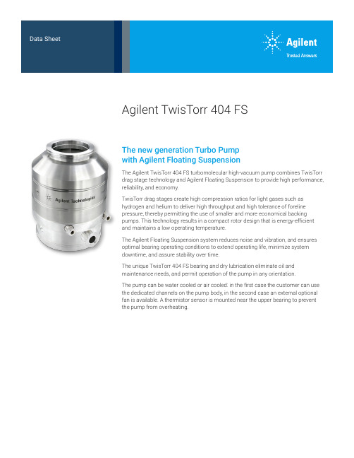
Agilent TwisTorr 404 FSThe new generation Turbo Pumpwith Agilent Floating SuspensionThe Agilent TwisTorr 404 FS turbomolecular high-vacuum pump combines TwisTorr drag stage technology and Agilent Floating Suspension to provide high performance, reliability, and economy.TwisTorr drag stages create high compression ratios for light gases such as hydrogen and helium to deliver high throughput and high tolerance of foreline pressure, thereby permitting the use of smaller and more economical backing pumps. This technology results in a compact rotor design that is energy-efficient and maintains a low operating temperature.The Agilent Floating Suspension system reduces noise and vibration, and ensures optimal bearing operating conditions to extend operating life, minimize system downtime, and assure stability over time.The unique TwisTorr 404 FS bearing and dry lubrication eliminate oil and maintenance needs, and permit operation of the pump in any orientation.The pump can be water cooled or air cooled: in the first case the customer can use the dedicated channels on the pump body, in the second case an external optional fan is available. A thermistor sensor is mounted near the upper bearing to prevent the pump from overheating.2D i m e n s i o n s : m i l l i m e t e r s [i n c h e s ]Technical Specifications229.449.03159.206.27229.449.03207.508.17273.9410.79129.905.11ISO 100K115.254.54117.254.6212°0'1104.33104.754.12VENT SCREWELECTRICAL CONNECTOR FORELINE FLANGE KF25Q.ty 3 holes M6 at 120° on Ø160for NAVIGATOR CNTRPURGE SCREWWATERCOOLING 1/8G239.449.43169.206.66239.449.43207.508.17 283.9411.181656.50CFF 6"115.254.54117.254.62 12°0'1104.33104.754.12VENT SCREWELECTRICAL CONNECTORFORELINE FLANGE KF25Q.ty 3 holes M6 at 120° on Ø160for NAVIGATOR CNTR PURGE SCREWWATERCOOLING 1/8G234.449.23164.206.46234.449.23207.508.17278.9410.981656.50ISO 100F115.254.54117.254.6212°0'1104.33104.754.12VENT SCREWELECTRICAL CONNECTORFORELINE FLANGE KF25Q.ty 3 holes M6 at 120° on Ø160for NAVIGATOR CNTRPURGE SCREWWATERCOOLING 1/8GOrdering InformationPumping SpeedCompression Ratio3Contact informationhttps:///en/product/vacuum-technologies/turbo-pumps-controllers/turbo-pumps/twistorr-404-fs-turbo-pumpDE44480.6169560185This information is subject to change without notice.© Agilent Technologies, Inc. 2021Printed in the USA, October 18, 20215991-9475ENAmericasAgilent Technologies 121 Hartwell Avenue,Lexington, MA 02421 USA Toll free: +1 800 882 7426****************************Europe, Middle East, Africa, India Agilent Technologies Italia SpA Via F.lli Varian 54,10040 Leini (Torino), Italy Tel: +39 011 9979 111Toll free: 00 800 234 234 00****************************ChinaBeijing Office Agilent Technologies (China) Co. Ltd.No.3, Wang Jing Bei Lu,Chao Yang District,Beijing, 100102, China Toll free: 800 820 6778***************************For more information, please contact your Agilent representative or visit/chem/vacuum where you can chat live with a vacuum expert.。
- 1、下载文档前请自行甄别文档内容的完整性,平台不提供额外的编辑、内容补充、找答案等附加服务。
- 2、"仅部分预览"的文档,不可在线预览部分如存在完整性等问题,可反馈申请退款(可完整预览的文档不适用该条件!)。
- 3、如文档侵犯您的权益,请联系客服反馈,我们会尽快为您处理(人工客服工作时间:9:00-18:30)。
AOTF404
D S
Symbol
Min Typ
Max
Units BV DSS 105
V 1T J =55°C
5I GSS 100nA V GS(th) 2.5 3.2
4
V I D(ON)90
A 2128T J =125°C
394723.531
m Ωg FS 73S V SD 0.72
1V I S
55
A C iss 1630
20382445pF C oss 142204265pF C rss 5185119pF R g
0.65 1.3 1.95ΩQ g (10V)30.8
38.546nC Q gs 6.489.6nC Q gd 8
1014nC t D(on)12.7ns t r 8.2ns t D(off)31.5ns t f 11.2ns t rr 344964ns Q rr
337
481
625nC
THIS PRODUCT HAS BEEN DESIGNED AND QUALIFIED FOR THE CONSUMER MARKET. APPLICATIONS OR USES AS CRITICAL COMPONENTS IN LIFE SUPPORT DEVICES OR SYSTEMS ARE NOT AUTHORIZED. AOS DOES NOT ASSUME ANY LIABILITY ARISING OUT OF SUCH APPLICATIONS OR USES OF ITS PRODUCTS. AOS RESERVES THE RIGHT TO IMPROVE PRODUCT DESIGN,FUNCTIONS AND RELIABILITY WITHOUT NOTICE.
Body Diode Reverse Recovery Time
I F =20A, dI/dt=500A/µs
Body Diode Reverse Recovery Charge I F =20A, dI/dt=500A/µs
Turn-On DelayTime V GS =10V, V DS =50V, R L =2.7Ω, R GEN =3Ω
Turn-On Rise Time Turn-Off DelayTime Turn-Off Fall Time
Gate resistance
V GS =0V, V DS =0V, f=1MHz
SWITCHING PARAMETERS Total Gate Charge V GS =10V, V DS =50V, I D =20A
Gate Source Charge Gate Drain Charge Maximum Body-Diode Continuous Current
DYNAMIC PARAMETERS Input Capacitance V GS =0V, V DS =25V, f=1MHz Output Capacitance Reverse Transfer Capacitance Forward Transconductance
V DS =5V, I D =20A
Diode Forward Voltage I S =1A, V GS =0V
R DS(ON)Static Drain-Source On-Resistance
V GS =10V, I D =20A
m ΩV GS =6V, I D =20A
Gate Threshold Voltage V DS =V GS , I D =250µA On state drain current
V GS =10V, V DS =5V µA Gate-Body leakage current V DS =0V, V GS =±25V Drain-Source Breakdown Voltage I D =10mA, V GS =0V I DSS Zero Gate Voltage Drain Current V DS =105V, V GS =0V
Electrical Characteristics (T J =25°C unless otherwise noted)Parameter Conditions STATIC PARAMETERS A: The value of R θJA is measured with the device mounted on 1in 2 FR-4 board with 2oz. Copper, in a still air environment with T A =25°C. The Power dissipation P DSM is based on R θJA and the maximum allowed junction temperature of 150°C. The value in any given application depends on the user's specific board design, and the maximum temperature of 175°C may be used if the PCB allows it.
B. The power dissipation P D is based on T J(MAX)=175°C, using junction-to-case thermal resistance, and is more useful in setting the upper dissipation limit for cases where additional heatsinking is used.
C: Repetitive rating, pulse width limited by junction temperature T J(MAX)=175°C.
D. The R θJA is the sum of the thermal impedence from junction to case R θJC and case to ambient.
E. The static characteristics in Figures 1 to 6 are obtained using <300 µs pulses, duty cycle 0.5% max.
F. These curves are based on the junction-to-case thermal impedence which is measured with the device mounted to a large heatsink, assuming a maximum junction temperature of T J(MAX)=175°C.
G. The maximum current rating is limited by bond-wires.
H. These tests are performed with the device mounted on 1 in 2 FR-4 board with 2oz. Copper, in a still air environment with T A =25°C. The SOA curve provides a single pulse rating. Rev0: Otc. 2008
Vds
Charge Gate Charge Test Circuit & Waveform
Vdd Vdd
Resistive Switching Test Circuit & Waveforms
Vdd
Vds
Id
Vgs
BV
I Unclamped Inductive Switching (UIS) Test Circuit & Waveforms
AR
DSS
2
E = 1/2 LI AR
AR。