Rational Structural Dynamic Loads for Optimum High-Speed Multi-Hull Ship Designs
结构力学(structuralmechanics)
结构力学(structural mechanics)Structural mechanics is a branch of solid mechanics, which mainly studies the laws of force and force transfer of engineering structures, and how to optimize the structure. The so-called engineering structure refers to the system that can bear and transfer the external load, including the rod, plate, shell and their combinations, such as aircraft fuselage and wing, bridge, roof truss and load-bearing wall.The task is to study structural mechanics in engineering structure under external load stress, strain and displacement law; analysis of different forms and different materials of engineering structure, analysis method and calculation formula for engineering design; engineering structure subjected to external forces and transfer; research and development of new engineering structure.The natural structure observed in nature, such as roots, stems and leaves of plants, animal bones, egg shell, can find their strength and stiffness related not only to material, but also closely related with their shape, many engineering structures are natural structures created out of inspiration. The structure design should not only consider the strength and stiffness of the structure, but also to do material saving and light weight. The weight is particularly important for some projects, such as aircraft weight can make the aircraft flight range, rising quickly, high speed and low energy consumption.A brief history of structural mechanicsHumans began to manufacture all kinds of artifacts in ancienttimes, such as houses, boats and bow, musical instruments, these are simple structure. With the progress of society, people for structural design patterns and the strength and stiffness of the structure has been gradually recognized, and accumulated experience, which is reflected in the brilliant achievements of ancient buildings, such as Egypt, Pyramid, China the Great Wall, Zhaozhou Anji bridge, Beijing the Imperial Palace. Despite the presence of mechanics in these structures in knowledge, but did not form a discipline.As far as the basic principles and methods are concerned, structural mechanics is developed simultaneously with theoretical mechanics and material mechanics. Therefore, structural mechanics is integrated with theoretical mechanics and material mechanics in the initial stage of development. By the early nineteenth Century, due to the development of industry, people began to design a variety of large-scale engineering structures, the design of these structures should be more accurate analysis and calculation. Therefore, the analysis theory and analysis method of engineering structure began to be independent. By the middle of the nineteenth Century, structural mechanics began to become an independent discipline.Many computational theories and methods of structural mechanics appeared in the nineteenth Century. At France in 1826 proposed a normal method for solving statically indeterminate structure problems. From 1830s onwards, due to the bridge by train, not only need to consider the bridge under static load problems, must also be considered to withstand the dynamic load, because the bridge span increases, the metal truss structure.In the decades since 1847, scholars have studied the force analysis of statically determinate truss structures by means of graphic method and analytic method, which laid the foundation of truss theory. In 1864, Maxwell established the unit load method and the displacement reciprocal theorem, and calculated the displacement of the truss by the unit load method. Thus, scholars finally got the method to understand the statically indeterminate problem.After the establishment of the basic theory, the new structure and its corresponding theory have been continuously developed while solving the problems of the original structure. From the late nineteenth Century to the early twentieth Century, scholars carried out a lot of mechanical research on the ship structure, and studied the dynamic theory of the beam under the moving load, as well as the problems of free vibration and forced vibration.In the early twentieth Century, the development of Aeronautical Engineering promoted the stress and deformation analysis of thin-walled structures and stiffened plates and shells, and studied the stability problems. At the same time, bridges and buildings started to use a large number of reinforced concrete materials, this requires scientists to study systematically the steel structure, the displacement method was founded in Germany in 1914 of the Dixon, for solving the problem of rigid frame and continuous beam etc.. Later, in the 20~30 century, some simple calculation methods were put forward for the complex statically indeterminate bar structures, so that the general designers could master and use them.By 1920s, people have put forward the idea of honeycomb sandwich structure. According to the concept of limit state of structure, scholars have come up with a new design and calculation theory for beams, plates and frames on elastic foundations. The mechanical problems of structures subjected to various dynamic loads (especially the action of earthquakes) have been studied in many aspects, such as experiment and theory. With the development of structural mechanics, fatigue problems, fracture problems and composite structure problems have entered the field of structural mechanics.In the middle of the twentieth Century, the advent of electronic computers and finite element methods made it possible to make complex calculations of large structures, thus bringing the level of research and application of structural mechanics to a new level.The discipline system of structural mechanicsThe general structural mechanics according to the different nature and its research object is the static structure, structural dynamics, theory, structure, fracture and fatigue theory of rod structure theory, theory of thin-walled structure and overall structure theory etc..Structural statics is the first branch of structural mechanics. It mainly studies the elastic-plastic deformation and stress state of engineering structures under static loads, and the structural optimization problems. Static load refers to the load that does not change with time, the load that changesslowly, and also can be regarded as static load approximately. Structural statics is the basis of other branches of structural mechanics.Structural dynamics is a branch of study on the response and performance of engineering structures under dynamic loads. Dynamic load refers to the load that changes with time. Under dynamic load, the stress, strain and displacement in the structure must be the function of time. Because of the time factor, the research content of structural dynamics is generally more complex than that of structural statics.The theory of structural stability is the branch of study on the stability of Engineering structures. Slender and thin structures are widely used in modern engineering, such as thin rods, thin plates and thin shells. When they are compressed, they will lose stability (wrinkling or buckling) when the internal stress is less than the yield limit, that is to say, the structure produces too large deformation, thus reducing and even completely losing the bearing capacity. Large deformation also affects other requirements of structural design, such as aerodynamic performance of aircraft. The most important content of structural stability theory is to determine the critical buckling load of structures.Structural fracture and fatigue theory is the study of engineering structures are inevitable because of internal crack, crack under external load expansion caused by fracture, caused by fatigue failure would be expanded subject in smaller amplitude under alternating load. Now, the research history of fracture and fatigue is not long and imperfect, but the theoryof fracture and fatigue is developing very fast.In structural mechanics, theoretical and experimental studies on various engineering structures, based on the research object also formed some research fields, which are the main truss structure theory, the theory of thin-walled structures and the overall structure of the theory of three categories. The whole structure is made of raw materials, machined by mechanical milling or by chemical etching. It is especially suitable for some boundary conditions and is often used as variable thickness structure. With the development of science and technology, many new structures emerge, such as sandwich structure and composite structure appearing in the middle of twentieth Century.The research methods of structural mechanics mainly include three kinds of analysis, experimental research, theoretical analysis and calculation of Engineering structure. In the structural design and research, these three aspects are often alternate and complement each other.The use analysis is in the structure use process, carries on the analysis, the comparison and the summary to the structure appears, this is easy and reliable one kind of research method. The use analysis plays an important role in the evaluation and improvement of structure. The newly designed structures also need to be used to test the performance.The experimental research can provide an important basis for the identification of structure, which is also the main means to test and develop the theory and calculation method ofstructural mechanics. The experimental research can be divided into three types: model experiment, real structural component experiment and real structure experiment. For example,Aircraft ground failure test, flight test and vehicle collision test, etc..The mechanical structure usually takes more manpower, material and financial resources, so only to a limited degree, especially in the early stages of the structural design, generally rely on theoretical analysis and calculation of the structural components.In the field of solid mechanics, provides the basic knowledge necessary for the development of material mechanics, structural mechanics, elastic mechanics and plastic mechanics is the theoretical basis of structural mechanics, structural mechanics is also combined with other physical disciplines form many interdisciplinary, such as fluid elastic force etc..Structural mechanics is an ancient discipline, and it is also a rapidly developing subject. A large number of new engineering materials and new engineering structures have provided new research contents and new requirements for structural mechanics. The development of computer provides a powerful computational tool for structural mechanics. On the other hand, structural mechanics also plays an important role in the development of mathematics and other subjects. The emergence and development of the finite element method is closely related to the study of structural mechanics.。
抗震计算桥墩屈服判断
抗震计算桥墩屈服判断英文回答:Seismic design is an essential aspect of engineering structures, especially for bridges that are subjected to dynamic loads during earthquakes. In order to ensure the safety and structural integrity of bridge piers, it is necessary to evaluate their yielding behavior under seismic forces. The yielding of a bridge pier refers to the point at which the material in the pier starts to deform plastically, indicating that it has reached its maximum capacity to resist the applied loads.There are several methods to determine the yielding behavior of bridge piers. One commonly used approach is to calculate the yield strength of the materials used in the construction of the pier. The yield strength is the maximum stress that a material can withstand without permanent deformation. By comparing the calculated yield strength with the expected seismic forces, engineers can assesswhether the pier will yield or remain elastic under the given loading conditions.Another method to evaluate the yielding behavior of bridge piers is through the use of yield displacement criteria. This criterion considers the displacement of the pier at which yielding occurs, rather than the stresslevels in the materials. The yield displacement is determined based on the expected seismic forces and the stiffness of the pier. If the calculated yield displacement is smaller than the expected displacement during an earthquake, it indicates that the pier will yield and undergo plastic deformation.In addition to these methods, engineers also take into account the ductility of the bridge piers. Ductility refers to the ability of a material to deform plastically without failure. A high ductility is desirable in bridge piers as it allows them to absorb and dissipate energy during seismic events. This helps prevent sudden and catastrophic failure. By considering the ductility of the materials used in the piers and the expected seismic forces, engineers canassess the yielding behavior of the piers.To illustrate these concepts, let's consider an example. Imagine a bridge pier made of reinforced concrete. The engineer calculates the yield strength of the concrete and finds it to be 30 MPa. The expected seismic forces on the pier are estimated to be 20 MPa. Since the calculated yield strength is higher than the expected forces, the engineer concludes that the pier will remain elastic and not yield under the seismic loads.中文回答:抗震设计是工程结构中的重要方面,特别是对于在地震中承受动态荷载的桥梁而言。
Unit 3 Structural Load

它们的实际重量可能在设计时还是个未知数。表列的
v.把(数字、事实) 列成表; 使成板[片] 材料密度常常低估了结构中实际的材料静荷载。 状,使成平面
• Some types of the dead load tend to be highly uncertain. This include pavement on bridges, which may be paved several times over a period of time, or
• They are developed to help achieve the desired Ievel of reliability of a structure based on probabilistic studies that take into account the load's originating cause, recurrence, distribution, and static or dynamic nature.
v. n.下垂,凹陷
n.队列,排成直 线; 结盟; 校直, 调整
• Similarly, earth fill over an underground structure may be up to several feet thicker than assumed and may or may not be saturated with water. In the construction of thin
• 建筑规范要求结构的设计和建造能经受使用 期限内的一切作用,保证安全性,以及适用 性。这些规范规定了各种结构类型、不同地 理位置、不同用途和材料的建筑承受的最小 荷载或作用。
• Structural loads are split into categories by their originating cause. Of course, in terms of the actual load on a structure, there is no difference between dead or live loading, but the split occurs for use in safety calculations or ease of analysis on complex models . • 结构荷载根据其产生的原因分成不同的种类。当 然,就结构实际承受的载荷而言,恒载荷和活载 荷并没有差别,但是在计算安全系数或减轻复杂 模型的分析难度时就会有差别。
机械设计制造及其自动化专业英语课后题

Aliuminum 铝copper 铜nicke 镍titanium 钛structural strength 结构强度deep drawing 拉伸加工hardenability 硬化性machinability 可加工性cold drawn冷拔steel sheet钢板percent reduction in area 断面收缩率endurance limit 疲劳极限rolled-steel shapes 轧制钢板corrosion resistance 抗腐蚀性rupture 断裂non-ferrous 非钢的stress-strain curve 应力应变曲线yield point 屈服点percentage elongation 伸长率necking 颈缩sensitivity 灵敏性Kinematic elements运动员素External appearance外观Sound judgment准确判断Fatigue strenghth结构强度Enviroment damage环境损害Ductile or brittle韧性或脆性Blow out吹息Interference fit joint干涉配合关节定义 defintion力 f orce轴axle非金属nometal结构structure载荷load用途use性质properties低碳钢low-carbon高强度钢hinger-strengt steel热处理heat treatment屈服强度yield strength弹性模量elastic modulus伸长率percentage elongation韧性toughness内应力internal stresses应变硬化strain hardening横截面cross-sectional area断面收缩率reduction in area比例极限limit of proportionality屈服极限yield limit延性ductiliy机械性质mechanical propertiece 用..除..divide byT he distinction between a mental and nonmetal is not away clear cutEngineers would not be particularly interest in such a metal if absolute pure metal were to be producedOf the 50 or so metallic elements,only a few produce and used in large quantities in engineer practices.In the elastic range,the deformation of the specimen disappeared after the load was removed.Logically speaking,once the elastic limit is exceeded,the metal should start to yield,and finally break,without any increase in the value of stressThe purpose of design calculations is to predict the stress or deformation in the part in order that it may safely carry the load which will be imposed on it and that it my last for the expected life of machineDynamic loads are generally more dangerous than strain loads and fatigue strength must be consideredWhen loaded the material deforms and the amount of deformation depends on the size of the load。
独立悬架系统零部件动态载荷计算方法

摘要在车辆行驶过程中,悬架系统各零部件承受并传递来自轮胎及车身的多种动态载荷,这些载荷是进行悬架系统的结构强度、疲劳分析必不可少的边界条件,也是指导悬架以及车身结构优化的重要参数。
本文结合多体动力学相关理论和Udwadia-Kalaba方程的约束处理方法,以轮心六分力为输入,对独立悬架系统各零部件的动态载荷计算方法及其应用展开了研究。
具体研究内容如下:首先以不含衬套连接的前双横臂、后五连杆悬架系统作为研究对象,基于Udwadia-Kalaba方程的基本思想,分别建立了无约束系统动力学模型、系统约束方程以及完整的前后悬架动力学模型;推导了系统总约束力的分解过程从而得到各零部件硬点载荷的解析表达式;在MATLAB中分别建立上述模型进行仿真计算,与ADAMS/Car的仿真结果进行对比,验证了方法的正确性。
②然后考虑含橡胶衬套的连接方式,建立了表征衬套动态特性的数学模型;针对前后悬架在衬套分布位置上的差异,以及与无衬套模型在建模方法上的区别与联系,分别推导了前后悬架动力学建模以及各硬点载荷的计算过程;在MATLAB及ADAMS/Car中进行仿真计算,验证了上述方法的正确性。
③其次以某SUV为对象开展了六分力测试试验,测量了实车在两种路面工况中的轮心六分力,结合前文建立的悬架动力学模型,预测得到了前悬架控制臂各硬点处的动态载荷;以预测载荷及六分力作为边界条件,对控制臂在两种工况下的疲劳寿命进行了分析。
④最后为便于方法的使用,分别完善了麦弗逊、四连杆等其余独立悬架的建模计算过程,在MATLAB/GUI中设计了一种独立悬架系统建模及动态载荷计算的仿真平台,实现了多种悬架的参数化建模。
本文将Udwadia-Kalaba方程应用到汽车独立悬架研究领域,结合多体动力学相关理论,详细地推导了独立悬架动力学建模及零部件动态载荷的计算过程。
研究过程中将理论与实践相结合,可为这一类含约束复杂机械系统的建模计算提供一种新思路。
Structural mechanics 中的专业词汇

Structural mechanics 中的专业词汇PREFACE AND CHAPTER 1Structural mechanics 结构力学Structural analysis 结构分析Statically determinate structures 静定结构Statically indeterminate structures超静定结构Matrix analysis of structures 结构矩阵分析Plastic analysis of structures 结构塑性分析Dynamic analysis of structures 结构动力分析Illustrative example 例题Problems 习题In civil construction 在土木工程建设中Geometric dimension 几何尺度Framed structure 杆系结构Cross-section 横截面Rectangular cross-section 矩形截面Radius 半径Diameter 直径Slab 板Shell 壳Thin-walled structure 薄壁结构Massive structure 块体结构The same order of magnitude 大小同量级Theory of Elasticity 弹性力学Aspect 方面Application of loads 荷载的作用Forces and deformations 力和形变Internal forces 内力Reasonable simplicity 合理的简化Computing model 计算模型In structural engineering 在结构工程中Dead loads 静荷载Live loads 活荷载Dynamic loads 动力荷载Movable loads 移动荷载Moving loads 运动荷载Static loads 静力荷载Response of a structure 结构响应Blast loads 爆炸荷载Impact loads 冲击荷载Centrifugal force 离心力External effect 外部作用Support settlement 支座沉陷Manufacture discrepancy 制造误差Shrinkage of material 材料收缩In generalized sense 在广义上Behavior of a structure 结构的行为Members 构件Bending moment 弯矩Shearing force 剪力Normal force 轴力Internal force component 内力分量Lateral dimension 横向尺寸Reinforced concrete beam 钢筋砼梁Engineering structure 工程结构Three dimensional 三维的Planar(plane) structure 平面结构To lie in the same plane 处在同一平面Space structure 空间结构Simplification of supports 支座的简化Restraint 约束Stationary foundation 固定的基础Roller support 辊柱支座(链杆支座)Link support 链杆支座Perpendicular to 垂直于……Hinge support 固定铰支座Horizontal 水平的Vertical 竖直的Be parallel to each other 相互平行Displacement 位移Links 链杆Rotation 转角,转动A couple 一个力偶Fixed support 固定支座Translation 平移Isometrically 等距地Respectively 分别地Simplification of joints 节点的简化Hinge joint 铰结Rigid joint 刚结Monolithic body 整体,一体Beam 梁Flexural member 受弯构件Transverse force 横向力Frame 框架Bend 弯2Shear 剪Tense 拉Compress 压Arch 拱Reaction 反力Truss 桁架Composite structure 组合结构Superposition principle 叠加原理Be subjected to 承受……Linearly 线性地Linearly elastic 线弹性的Increment 增量Be proportional to 与…成正比Stress 应力Strain 应变CHAPTER 2Geometric stability 几何稳定性Geometrically stable 几何稳定的Unstable system 不稳定体系Degrees of freedom 自由度By definition 根据定义Independent coordinate 独立坐标Planar coordinate system 平面坐标系Three dimensional coordinate system三维(空间)坐标系Rigid body 刚体Joint 节(结)点Mutual(relative) displacement 相对位移Be equivalent to 等价于…Multiple hinge 多重铰Multiple rigid joint 多重刚结点Imposed restraint 施加的约束Insufficient 不足的Sufficient 足够的Redundant 多余的Redundant restraint 多余约束Arrangement of restraints 约束的布置Necessary condition 必要条件Sufficient condition 充分条件Geometric construction analysis 几何构造分析Definite conclusion 确定的结论Substitute into 代入…Assembly 集合Kinematic analysis 机动分析A hinged triangle 一个铰接三角形Lying on the same straight line 位于同一直线Infinitesimal displacement 无穷小位移Infinitesimal rotation 无穷小转角Instantaneously unstable system 瞬变体系Jointed pairwise 两两相连的Statically determinate multi-span beam 多跨静定梁Internal stable 内部稳定的Internal stability 内部稳定性Disregard 忽视,不考虑AB and CD Intersecting at point O AB 和CD相交于点OInstantaneous centre of rotation 瞬时转动中心Instantaneous hinge 瞬铰Static determinacy 静力确定性Static equilibrium equation 静力平衡方程Arbitrary cross section 任意横截面Isolated free body 脱离(隔离)体Unique solution 唯一的解Coupled equation 耦合的方程Contradictory 矛盾的Infinite number of solutions 无穷多个解Simultaneous equations 联立方程In quantitative sense 在数量上Projection equilibrium equation 投影平衡方程Determinant method 行列式法则(克莱母法则)Determinant 行列式Coefficient of the equations 方程未知量的系数Static characteristic 静力特性Space system 空间体系Infinitely far away 无穷远处CHAPTER 3Fundamental 基础,基本原理Individual member 单一的构件Element 单元Resultant 合力Axial direction 轴向3 Axial tension 轴向拉伸Positive 正的Negative 负的Compression in the upper fibers上边受压Tension in the lower fibers 下边受拉Normal direction 法向Axis 轴线Clockwise moment 顺时针力矩Counter clockwise moment 反时钟力矩Free body 隔离体Sign convention 符号规定Moment diagram 弯矩图Tensile side of a member 构件的受拉边Method of section 截面法Monolithic system 整体系统Algebraic sum 代数和Magnitude 大小Moments about the centroid ofcross section 对截面中心的力矩Mathematical relation 数学关系Internal force diagram 内力图Differential element 微分单元As indicated 正如所示Distributed loads 分布荷载Intensity 集度Summing moments about an axisthrough the left hand face of theelement 关于穿过该单元左截面的某轴求力矩之和Higher-order term 高阶项A segment 一段Rightward 向右Downward 向下Separately 分别地Slope 斜率Extreme moment 极值弯矩Curvature 曲率Uniformly distributed 均匀分布Linear function 线性函数Inclined straight line 斜直线Quadratic function 二次函数Parabolic curve 抛物线Concave 下凸的Concentrated load 集中荷载Incremental relation 增量关系To the immediate left and tight of P P的左邻和右邻Abrupt change 突变Abruptly 突然地Integral relation 积分关系Difference between A and B A和B 的差Sum of A and B A和B的和Figure 图形Construction of shearing force diagram剪力图的绘制Terminal point 终点End couple 杆端力矩Dashed line 虚线Ordinate 纵坐标Superimpose 叠加Concave parabola 下凸抛物线Corresponding ordinate 相应的纵坐标Similar triangle 相似三角形Inclined member 斜杆Per meter 每米Curved member 曲杆Tangential direction 切向Normal direction 法向Curvature radius 曲率半径Infinitesimally small 无穷小Approach to infinity 趋于无穷Radial distributed 径向分布的Arc 弧Basic stable portion 基本部分Subsidiary portion 附属部分Symmetrical 对称的Unsymmetrical 非对称的Horizontal thrust 水平推力Construct M and Q diagrams 绘制M和Q图CHAPTER 4Statically determinate multispan beam静定多跨连续梁Static method 静力法Constituent 组成的Cantilever beam 悬臂梁Similarly 同样地(同理)Overhang beam 伸臂梁Simple supported beam 简支梁Method of virtual work 虚功法Kinematic method 机动法Principle of virtual displacement 虚位移原理4Principle of virtual work 虚功原理Virtual displacement 虚位移Consistent with 与…相容的Mechanism 机构Virtual work equation 虚功方程Unknown 未知的Projection along the force 在力方向上的投影Product of magnitude of the force and the magnitude of the displacement 力的大小与位移大小的乘积Angular displacement 角位移Corresponding displacement 相应的位移Substitute for 替换…Infinitesimal virtual displacement 无穷小虚位移In this circumstance 在这种情况下Deflect 偏转Equal in magnitude but opposite in direction 大小相等方向相反Instructive 有启发的CHAPTER 5Pinned joint 铰接Subscript 下标Control section 控制截面Foundation 基础Order of calculation 求解顺序Differential relation between M and external loads M和外力的微分关系Tension in the right fiber 右边纤维受拉Reserve 保留End bending moment 杆端弯矩Sign indication 符号标定Associate shearing force 相应的剪力Keep balance 保持平衡Uniformly distributed loads 均布荷载Satisfaction of the projection equilibrium equations 平衡方程的满足Control ordinate 控制坐标Be perpendicular to 垂直于…CHAPTER 6Span of an arch 拱跨Rise of an arch 拱的矢高Symmetrical axis 对称轴Horizontal thrust 水平推力A three arched arch with a tie 拉杆三铰拱Flatten out 变平Arbitrary cross section 任意截面Axis of abscissa 横坐标轴First derivative 一阶导数Conic parabola 二次抛物线Tabulate 把…制成表格Table 表格Column 列The cipher of column 9 第9列的值Lay off 画出…Masonry construction 砌石建筑Abutment 底座,桥墩Line of pressure 压力线Resultant 合力By graphical method 利用几何法Force Polygon 力多边形Pole 极点Intersection point 交点Funicular polygon 索多边形Polygon of resultants 合力多边形Action line for resultant 23 合力23的作用线Respective string 各自的索线In direct proportion to 正比于…Optimal centre line of arch 合理拱轴线Theoretical volume 理论值Primarily stationary load主要由固定荷载作用Reckon from 从…开始算Configuration 形状As a consequence 结果,因而Hydraulic pressure 静水压力Circular arc 圆弧A curve of circular arc 圆弧曲线Bisector 二等分线,平分线Annular shape 圆环状Under earth pressure 在土压力作用下Crown hinge 顶铰Under this circumstance 在这种情况下Differentiate with respect to x关于x求导Differential equation 微分方程Hyperbolic function 双曲函数Boundary condition 边界条件Whence 据此,由此Catenoid 悬链线5Cable 吊索Suspension system 悬挂体系A series of linear segments 一系列直线段Distortion 变形Deflection 挠度Sag 下垂度Assumption 假定Unknown force 未知力CHAPTER 7Connected by pins 用铰连接Tower 塔Roof structure 屋架(屋面)结构Frictionless pin 光滑铰Two-force member 二力杆Heavy bolted joint 强螺栓连接节点Welded joint 焊接节点Primary stress 主要应力Subsidiary stress 次要(附加)应力Top chord 上弦杆Bottom chord 下弦杆web member 腹杆Diagonals and verticals 斜杆和竖杆Panel point 节点Panel 节间Through truss 穿越(下承式)桁架Desk truss 上承式桁架Simple truss 简单桁架In alphabetical order 以字母顺序Compound truss 联合桁架Rigid framework 刚性构架Nonparallel nonconcurrent links 不相互平行也不相交于一点的链杆Cross-hatched 画阴影线的Complex truss 复杂桁架Joint method 节点法Section method 截面法concurrent forces 汇交力系Expedient 方便的Inactive member 零杆Moment centre 力矩中心Projection axis 投影轴线Pass a section 做一个截面Exceptional member 单杆Subdivided truss 再分式桁架Sub-diagonal 辅助(次)斜杆Sub-vertical 辅助(次)竖杆Sub-truss 辅助(次,子)桁架Sub-member 辅助(次)杆Sub-joint 辅助(次)节点Horseshoe-shaped 马蹄形的Graphical method 作图法Algebraic method 代数方法vertex of the polygon多边形的顶点arrow of a force 力的箭头successively 连续地by scaling 通过度量repetitional work 重复性的工作supplement 补充method of substitute member 替换杆法method of initial parameter 初参数法closed loop 闭合圈space truss 空间桁架dome 圆屋顶derrick 塔架spherical hinge 球形铰triangular pyramid 三棱锥,四面形, 四面体odd member 单杆collinear 在同一直线上的foregoing discussion 前述的讨论beam member 梁式杆flexural member 受弯杆composite joint 复合节点self-equilibrium force system 自平衡力系statically equivalent load 静力等效荷载girder 桁架梁parallel chord truss 平行弦桁架non- parallel chord truss 非平行弦桁架roof truss 屋面桁架arched truss 拱桁架(桁架拱)polygonal line truss 折线桁架designated member 指定的杆absolute value 绝对值CHAPTER 8Influence line 影响线Most severe internal forces 最不利内力Influence coefficient 影响系数Dimension 量纲Dimensionless 无量纲的6Expression 表达式Most unfavorable position 最不利位置Behavior of the structure 结构的行为Constructing influence line 作影响线Influence line for internal force内力影响线Virtual work 虚功Principle of virtual work 虚功原理Abscissa 横坐标Sign indication 符号标注To draw influence line 画影响线To be confined to 被限制在……Floor beam 楼面梁Girder 大梁,主梁Floor slab 楼板Without ambiguity 显然Eliminating a necessary restraint去除一个必要的约束Infinitesimal virtualdisplacement无穷小虚位移Vertical scale 竖标Relative angular displacement 相对角位移Relative transverse displacement相对横向位移A unit transverse slidingdisplacement 一个单位横向滑动位移Intact 未动的,完好的Three hinged arch 三铰拱A corresponding simple beam一个相应的简支梁Critical position 临界位置Most severe effect 最不利的影响Trial aided 试算By use of criteria 利用判据Standard truck 标准卡车Average loads 平均荷载Inequality 不等式Critical load position 临界荷载位置Increment 增量Decrement 减量Reverse 逆Reverse condition (d) 条件(d)的逆The peak of the triangular influencediagram 三角形影响图的顶点Numerically greatest 数量上最大的Extreme value 极值Vertexes of the influence diagram 影响图的顶点Absolute maximum bending moment 绝对最大弯矩Derivative 导数Equidistant 等距离的Without any loads going on or off thespan 没有任何荷载进入和离开梁跨A continuous function of x x的连续函数Mid-point of the span 跨中Midpoint of the span 跨中Dangerous section 危险截面Crane beam 吊车梁Envelope for bending moment 弯矩包罗图Envelope for shearing force 剪力包罗图An arbitrary section 一个任意截面Influence diagram 影响图Designated quantity 指定量值Bound of the bending moment variation弯矩变化的边界CHAPTER 9In structural design 在结构设计中Elastic displacement 弹性位移Indeterminate structure 超静定结构Most versatile method 最通用的方法Unit load method 单位荷载法Reciprocal theorem 互等定理Illustration of unit load method 单位荷载法的例子Supported settlement 支座沉降Lineardiplacement (translation) 线位移A compatible displacement 相容性位移Fictitious=virtual 虚的Virtual force 虚力Appropriate choice 适当的选择Sections adjacent to hinge C 铰C的相邻截面A unit virtual load 一个单位竖向位移A pair of unit couple 一对单位力偶Real work 实功An elastic prismatic bar 一个弹性等截面杆Elasticity modulus 弹性模量Cross-section area 横截面面积Generalized force 广义力Generalized displacement 广义位移Statically interdependent forces 静力相关力系Corresponding generalized displacement 相应的广义位移The angle of rotation θ转角θ7External work 外(力)功Internal work 内(力)功To be identical to 与……一致(样) A differential element 一个微分单元Differential virtual work 微分虚功Strain energy 应变能Virtual stain energy 虚应变能Linear elastic structure 线弹性结构Internal virtual work 内力虚功Conservation law of energy 能量守恒定理External real work 外力实功The inverse of the curvature radius 曲率半径的倒数Compatible relations 相容关系Vanish 趋于零identity relation 恒等关系式unit virtual force 单位虚力virtual force system 虚力系real displacement 实位移real strain components 实应变分量an actual geometrical problem 一个实际的几何问题a fictitious equilibrium problem一个虚平衡问题difference of temperature 温差coefficient of thermal expansion温度膨胀系数axial strain 轴向应变likewise 同理sagging sense 下凸的moment of inertia 惯性矩axial rigidity 抗拉压刚度shearing rigidity 抗剪刚度flexural rigidity 抗弯刚度principal axis of cross section截面主轴twisting moment 扭矩twisting angle 扭转角differential segment 微分段torsional constant of the crosssection 截面扭转常数neutral axis 中性轴area moment 面积矩concrete member 砼凝土构件steel member 钢构件Poisson ratio 泊松比depth-span ratio 高跨比to be inversely proportional to与……成反比in parentheses 在括号中graph multiplication 图乘法the moment of the differentialarea with respect to y axis 微分面积对y轴的矩magnitude of areas 面积的大小location of their centroids 它们的形心位置3d-degree parabola 3次抛物线additional proviso 附加条件reinforced concrete 钢砼cross-sectional dimension 横截面尺寸elasto-plastic behaviour 弹塑性行为reduction factor 折减系数a pair of concentrated unit loads一对单位集中力reciprocal theorem 互等定理theorem of reciprocaldisplacements 位移互等定理theorem of reciprocal reactions反力互等定理reaction influence coefficients反力影响系数theorem of reciprocaldisplacement-reaction 反力位移互等定理support movement 支座移动to develop a general formula 推导通用公式column 柱CHAPTER 10Force method 力法Method of consistent deformation 一致变形法Redundant structure 超静定结构Unknown force 未知力Compatibility conditions 相容性条件Redundant unknown force 多余未知力Degree of indeterminacy 超静定度Internally indeterminate 内部超静定Primary system 基本体系Primary unknowns 基本未知量Passive force 被动力Active force 主动力Inconsistency n.不相容性,不一致性Embody 体现Superimpose 叠加Flexibility coefficient 柔度系数Canonical equation 标准方程Propped cantilever beam 有支(承)悬臂梁, 有支(承)伸臂梁Highly indeterminate structures 高阶超静定结构8Square matrix 方阵Symmetrical component 对称分量Antisymmetrical component 反对称分量Asymmetrical 不对称的Inflection point 反弯点Odd number of span 奇数跨Even number of span 偶数跨Method of elastic center 弹性中心法Rigid arm 刚臂Hingeless arch 无铰拱Numerator 分子Denominator 分母Quotient 商Central angle 中心角Nonprismatic member 变截面杆(构件)Trapezoid formula 梯形公式Parabolic formula 抛物线公式Reactant bending moment 抵抗弯矩Stiffness factor 刚度系数Nonyielding support 刚性支座Lack of fit 误差Redundant beam 超静定梁Qualitative influence line 定性影响线Quantitative influence line 定量影响线CHAPTER 11Slope-Deflection method 位移法(转角位移法)Displacement method 位移法Moment distribution method 弯矩分配法Varying section 变截面Slope-deflection equation 转角位移方程Rotation stiffness 转动刚度Slidely fixed 双链杆支座的Alongside 在旁边的Analogy 模拟,类比Portal frame 门形刚架Bent frame 排架Sideway 侧移Notion=conceptStiffness matrix 刚度矩阵Coefficient of thermal expansion 温度膨胀系数CHAPTER 12Systematic approach 系统化的方法Matrix algebra 矩阵代数Routinely programmed 常规地编程discretization 离散化beam element 梁单元truss element 桁架单元flexural element 弯曲单元element analysis 单元分析global analysis 整体分析nodal displacement vector .节点位移向量nodal resultant vector 节点力向量global stiffness equation 整体刚度方程governing equation 控制方程end force 杆端力end displacement 杆端位移stiffness matrix 刚度方程starting point 起点terminal point 终点the four entries 4项oriented in positive coordinate direction 指向坐标轴的正方向subvector 子向量main diagonal 主对角线main coefficients 主元素(主系数) secondary coefficients 副系数singular 奇异的determinant 行列式inverse of the matrix 矩阵的逆the origin of the system 坐标系的原点transformation matrix 坐标转换矩阵identity matrix 恒等矩阵submatrix 子矩阵stiffness method 刚度法nodal displacement vector 节点位移向量in the assembly 在集成过程中element contribution matrix 单元贡献矩阵global stiffness matrix 整体刚度矩阵governing equation 控制方程equivalent nodal loads 等效节点荷载non-nodal loads 非节点荷载artificial rotation restraint 人为的转动约束post-processing method 后处理法pre-processing method 前处理法plane truss 平面桁架coordinate transformation 坐标变换node number 节点编号9local number 局部码local code number 局部编码global code number 整体编码encircled superscript 画圈的上标a sparse matrix 一个稀疏矩阵a banded matrix 一个带状矩阵semi-bandwidth 半带宽loading conditions 荷载条件support arrangement 支座布置CHAPTER 13Method of moment distribution 弯矩分配法A procedure of successiveapproximation 一个逐步近似的过程Successive cycle of computation逐次的计算循环Joint translation 节点平移Rotational stiffness 转动刚度Distribution factor 分配系数Fraction of total moment 总弯矩的百分比Distribution moment at the near end 在近端的分配弯矩At the far end 在远端The ratio of the far end moment to thenear end moment 远端弯矩与近端弯矩的比值Carry-over factor 传递系数Basic moment distribution process 基本的弯矩分配过程An external nodal moment 一个外加的节点弯矩Artificial restraint 人为的约束In the lock state 在锁定状态Unlocking moment 释放弯矩Unbalanced moment 非平衡弯矩Eliminating the artificial restraint解除人为约束Carry-over moment 传递弯矩。
土木工程外文翻译-原文

外文原文Response of a reinforced concrete infilled-frame structure to removal of twoadjacent columnsMehrdad Sasani_Northeastern University, 400 Snell Engineering Center, Boston, MA 02115, UnitedStatesReceived 27 June 2007; received in revised form 26 December 2007; accepted 24January 2008Available online 19 March 2008AbstractThe response of Hotel San Diego, a six-story reinforced concrete infilled-frame structure, is evaluated following the simultaneous removal of two adjacent exterior columns. Analytical models of the structure using the Finite Element Method as well as the Applied Element Method are used to calculate global and local deformations. The analytical results show good agreement with experimental data. The structure resisted progressive collapse with a measured maximum vertical displacement of only one quarter of an inch mm). Deformation propagation over the height of the structure and the dynamic load redistribution following the column removal are experimentally and analytically evaluated and described. The difference between axial and flexural wave propagations is discussed. Three-dimensional Vierendeel (frame) action of the transverse and longitudinal frames with the participation of infill walls is identified as the major mechanism for redistribution of loads in the structure. The effects of two potential brittle modes of failure (fracture of beam sections without tensile reinforcement and reinforcing bar pull out) are described. The response of the structure due to additional gravity loads and in the absence of infill walls is analytically evaluated.c 2008 Elsevier Ltd. All rights reserved.Keywords: Progressive collapse; Load redistribution; Load resistance; Dynamic response; Nonlinear analysis; Brittle failure1.IntroductionThe principal scope of specifications is to provide general principles and computational methods in order to verify safet y of structures. The “safety factor ”, which according t o modern trends is independent of the nature and combination of the materials used, can usually be defined as the rati o between the conditions. This ratio is also proportional to the inverse of the probability ( risk ) of failure of th e structure.Failure has to be considered not only as overall collapse o f the structure but also as unserviceability or, according t o a more precise. Common definition. As the reaching of a “limit state ”which causes the construction not to acco mplish the task it was designed for. There are two categori es of limit state :(1)Ultimate limit sate, which corresponds to the highest value of the load-bearing capacity. Examples include local buckli ng or global instability of the structure; failure of some sections and subsequent transformation of the structure intoa mechanism; failure by fatigue; elastic or plastic deformati on or creep that cause a substantial change of the geometry of the structure; and sensitivity of the structure to alte rnating loads, to fire and to explosions.(2)Service limit states, which are functions of the use and durability of the structure. Examples include excessive defo rmations and displacements without instability; early or exces sive cracks; large vibrations; and corrosion.Computational methods used to verify structures with respect to the different safety conditions can be separated into: (1)Deterministic methods, in which the main parameters are co nsidered as nonrandom parameters.(2)Probabilistic methods, in which the main parameters are co nsidered as random parameters.Alternatively, with respect to the different use of factors of safety, computational methods can be separated into:(1)Allowable stress method, in which the stresses computed un der maximum loads are compared with the strength of the mat erial reduced by given safety factors.(2)Limit states method, in which the structure may be propor tioned on the basis of its maximum strength. This strength, as determined by rational analysis, shall not be less than that required to support a factored load equal to the sum of the factored live load and dead load ( ultimate state ).The stresses corresponding to working ( service ) conditions with unfactored live and dead loads are compared with pres cribed values ( service limit state ) . From the four poss ible combinations of the first two and second two methods, we can obtain some useful computational methods. Generally, t wo combinations prevail:(1)deterministic methods, which make use of allowable stresses . (2)Probabilistic methods, which make use of limit states. The main advantage of probabilistic approaches is that, at l east in theory, it is possible to scientifically take into account all random factors of safety, which are then combine d to define the safety factor. probabilistic approaches depend upon :(1) Random distribution of strength of materials with respect to the conditions of fabrication and erection ( scatter of the values of mechanical properties through out the structu re ); (2) Uncertainty of the geometry of the cross-section sand of the structure ( faults and imperfections due to fab rication and erection of the structure );(3) Uncertainty of the predicted live loads and dead loads acting on the structure; (4)Uncertainty related to the approx imation of the computational method used ( deviation of the actual stresses from computed stresses ). Furthermore, proba bilistic theories mean that the allowable risk can be based on several factors, such as :(1) Importance of the construction and gravity of the damage by its failure; (2)Number of human lives which can be thr eatened by this failure; (3)Possibility and/or likelihood of repairing the structure; (4) Predicted life of the structure. All these factors are related to economic and social consi derations such as:(1) Initial cost of the construction;(2) Amortization funds for the duration of the construction;(3) Cost of physical and material damage due to the failure of the construction;(4) Adverse impact on society;(5) Moral and psychological views.The definition of all these parameters, for a given saf ety factor, allows construction at the optimum cost. However, the difficulty of carrying out a complete probabilistic ana lysis has to be taken into account. For such an analysis t he laws of the distribution of the live load and its induc ed stresses, of the scatter of mechanical properties of mate rials, and of the geometry of the cross-sections and the st ructure have to be known. Furthermore, it is difficult to i nterpret the interaction between the law of distribution of strength and that of stresses because both depend upon the nature of the material, on the cross-sections and upon the load acting on the structure. These practical difficulties ca n be overcome in two ways. The first is to apply different safety factors to the material and to the loads, without necessarily adopting the probabilistic criterion. The second i s an approximate probabilistic method which introduces some s implifying assumptions ( semi-probabilistic methods ) . Aspart of mitigation programs to reduce the likelihood of mass casualties following local damage in structures, the General Services Administration [1] and the Department of Defense [2] developed regulations to evaluate progressive collapse resistance of structures. ASCE/SEI 7 [3] defines progressive collapse as the spread of an initial local failure fromelement to element eventually resulting in collapse of an entire structure or a disproportionately large part of it. Following the approaches proposed by Ellinwood and Leyendecker [4], ASCE/SEI 7 [3] defines two general methods for structural design of buildings to mitigate damage due to progressive collapse: indirect and direct design methods. General building codes and standards [3,5] use indirect design by increasing overall integrity of structures. Indirect design is also used in DOD [2]. Although the indirect design method can reduce the risk of progressive collapse [6,7] estimation of post-failure performance of structures designed based on such a method is not readily possible. One approach based on direct design methods to evaluate progressive collapse of structures is to study the effects of instantaneous removal of load-bearing elements, such as columns. GSA [1] and DOD [2] regulations require removal of one load bearing element. These regulations are meant to evaluate general integrity of structures and their capacity of redistributing the loads following severe damage to only one element. While such an approach provides insight as to the extent to which the structures are susceptible to progressive collapse, in reality, the initial damage can affect more than just one column. In this study, using analytical results that are verified against experimental data, the progressive collapse resistance of the Hotel San Diego is evaluated, following the simultaneous explosion (sudden removal) of two adjacent columns, one of which was a corner column. In order to explode the columns, explosives were inserted into predrilled holes in the columns. The columns were then well wrapped with a few layers of protective materials. Therefore, neither air blast nor flying fragments affected the structure.2. Building characteristicsHotel San Diego was constructed in 1914 with a south annex added in 1924. The annex included two separate buildings. Fig. 1 shows a south view of the hotel. Note that in the picture, the first and third stories of the hotel are covered with black fabric. The six story hotel had a non-ductile reinforced concrete (RC) frame structure with hollow clay tile exterior infill walls. The infills in the annex consisted of two withes (layers) of clay tiles with a total thickness of about 8 in (203 mm). The height of the first floor was about 190–800 m). The height of other floors and that of the top floor were 100–600 m) and 160–1000 m), respectively. Fig. 2 shows the second floor of one of the annex buildings. Fig. 3 shows a typical plan of this building, whose responsefollowing the simultaneous removal (explosion) of columns A2 and A3 in the first (ground) floor is evaluated in this paper. The floor system consisted of one-way joists running in the longitudinal direction (North–South), as shown in Fig. 3. Based on compression tests of two concrete samples, the average concrete compressive strength was estimated at about 4500 psi (31 MPa) for a standard concrete cylinder. The modulus of elasticity of concrete was estimated at 3820 ksi (26 300 MPa) [5]. Also, based on tension tests of two steel samples having 1/2 in mm) square sections, the yield and ultimate tensile strengths were found to be 62 ksi (427 MPa) and 87 ksi (600 MPa), respectively. The steel ultimate tensile strain was measured at . The modulus of elasticity of steel was set equal to 29 000 ksi (200 000 MPa). The building was scheduled to be demolished by implosion. As part of the demolition process, the infill walls were removed from the first and third floors. There was no live load in the building. All nonstructural elements including partitions, plumbing, and furniture were removed prior to implosion. Only beams, columns, joist floor and infill walls on the peripheral beams were present.3. SensorsConcrete and steel strain gages were used to measure changes in strains of beams and columns. Linear potentiometers were used to measure global and local deformations. The concrete strain gages were in (90 mm) long having a maximum strain limit of ±. The steel strain gages could measure up to a strain of ±. The strain gages could operate up to a several hundred kHz sampling rate. The sampling rate used in the experiment was 1000 Hz. Potentiometers were used to capture rotation (integral of curvature over a length) of the beam end regions and global displacementin the building, as described later. The potentiometers had a resolution of about in mm) and a maximum operational speed of about 40 in/s m/s), while the maximum recorded speed in the experiment was about 14 in/sm/s).4. Finite element modelUsing the finite element method (FEM), a model of the building was developed in the SAP2000 [8] computer program. The beams and columns are modeled with Bernoulli beam elements. Beams have T or L sections with effective flange width on each side of the web equal to four times the slab thickness [5]. Plastic hinges are assigned to all possible locations where steel bar yielding can occur, including the ends of elements as well as the reinforcing bar cut-off and bend locations. The characteristics of the plastic hinges are obtained using section analysesof the beams and columns and assuming a plastic hinge length equal to half of the section depth. The current version of SAP2000 [8] is not able to track formation of cracks in the elements. In order to find the proper flexural stiffness of sections, an iterative procedure is used as follows. First, the building is analyzed assuming all elements are uncracked. Then, moment demands in the elements are compared with their cracking bending moments, Mcr . The moment of inertia of beam and slab segments are reduced by a coefficient of [5], where the demand exceeds the Mcr. The exterior beam cracking bending moments under negative and positive moments, are 516 k in kN m) and 336 k in kN m), respectively. Note that no cracks were formed in the columns. Then the building is reanalyzed and moment diagrams are re-evaluated. This procedure is repeated until all of the cracked regions are properly identified and modeled.The beams in the building did not have top reinforcing bars except at the end regions (see Fig. 4). For instance, no top reinforcement was provided beyond the bend in beam A1–A2, 12 inches away from the face of column A1 (see Figs. 4 and 5). To model the potential loss of flexural strength in those sections, localized crack hinges were assigned at the critical locations where no top rebar was present. Flexural strengths of the hinges were set equal to Mcr. Such sections were assumed to lose their flexural strength when the imposed bending moments reached Mcr.The floor system consisted of joists in the longitudinal direction (North–South). Fig. 6 shows the cross section of a typical floor. In order to account for potential nonlinear response of slabs and joists, floors are molded by beam elements. Joists are modeled with T-sections, having effective flange width on each side of the web equal to four times the slab thickness [5]. Given the large joist spacing between axes 2 and 3, two rectangular beam elements with 20-inch wide sections are used between the joist and the longitudinal beams of axes 2 and 3 to model the slab in the longitudinal direction. To model the behavior of the slab in the transverse direction, equally spaced parallel beams with 20-inch wide rectangular sections are used. There is a difference between the shear flow in the slab and that in the beam elements with rectangular sections modeling the slab. Because of this, the torsional stiffness is setequal to one-half of that of the gross sections [9].The building had infill walls on 2nd, 4th, 5th and 6th floors on the spandrel beams with some openings . windows and doors). As mentioned before and as part of the demolition procedure, the infill walls in the 1st and 3rd floors were removed before the test. The infill walls were made of hollow clay tiles, which were in good condition. The net area of the clay tiles was about 1/2 of the gross area. The in-plane action of the infill walls contributes to the building stiffness and strength and affects the building response. Ignoring the effects of the infill walls and excluding them in the model would result in underestimating the building stiffness and strength.Using the SAP2000 computer program [8], two types of modeling for the infills are considered in this study: one uses two dimensional shell elements (Model A) and the other uses compressive struts (Model B) as suggested in FEMA356 [10] guidelines.. Model A (infills modeled by shell elements)Infill walls are modeled with shell elements. However, the current version of the SAP2000 computer program includes only linear shell elements and cannot account for cracking. The tensile strength of the infill walls is set equal to 26 psi, with a modulus of elasticity of 644 ksi [10]. Because the formation ofcracks has a significant effect on the stiffness of the infill walls, the following iterative procedure is used to account for crack formation:(1) Assuming the infill walls are linear and uncracked, a nonlinear time history analysis is run. Note that plastic hinges exist in the beam elements and the segments of the beam elements where moment demand exceeds the cracking moment have a reduced moment of inertia.(2) The cracking pattern in the infill wall is determined by comparingstresses in the shells developed during the analysis with the tensile strength of infills.(3) Nodes are separated at the locations where tensile stress exceeds tensile strength. These steps are continued until the crack regions are properly modeled.. Model B (infills modeled by struts)Infill walls are replaced with compressive struts as described in FEMA 356 [10] guidelines. Orientations of the struts are determined from the deformed shape of the structure after column removal and the location of openings.. Column removalRemoval of the columns is simulated with the following procedure. (1) The structure is analyzed under the permanent loads and the internal forces are determined at the ends of the columns, which will be removed.(2) The model is modified by removing columns A2 and A3 on the first floor. Again the structure is statically analyzed under permanent loads. In this case, the internal forces at the ends of removed columns found in the first step are applied externally to the structure along with permanent loads. Note that the results of this analysis are identical to those of step 1.(3) The equal and opposite column end forces that were applied in the second step are dynamically imposed on the ends of the removed column within one millisecond [11] to simulate the removal of the columns, and dynamic analysis is conducted.. Comparison of analytical and experimental resultsThe maximum calculated vertical displacement of the building occurs at joint A3 in the second floor. Fig. 7 shows the experimental andanalytical (Model A) vertical displacements of this joint (the AEM results will be discussed in the next section). Experimental data is obtained using the recordings of three potentiometers attached to joint A3 on one of their ends, and to the ground on the other ends. The peak displacements obtained experimentally and analytically (Model A) are in mm) and in mm), respectively, which differ only by about 4%. The experimental and analytical times corresponding to peak displacement are s and s, respectively. The analytical results show a permanent displacement of about in mm), which is about 14% smaller than the corresponding experimental value of in mm).Fig. 8 compares vertical displacement histories of joint A3 in the second floor estimated analytically based on Models A and B. As can be seen, modeling infills with struts (Model B) results in a maximum vertical displacement of joint A3 equal to about in mm), which is approximately 80% larger than the value obtained from Model A. Note that the results obtained from Model A are in close agreement with experimental results (see Fig. 7), while Model B significantly overestimates the deformation of the structure. If the maximum vertical displacement were larger, the infill walls were more severely cracked and the struts were more completely formed, the difference between the results of the two models (Models A and B) would be smaller.Fig. 9 compares the experimental and analytical (Model A) displacement of joint A2 in the second floor. Again, while the first peak vertical displacement obtained experimentally and analytically are in good agreement, the analytical permanent displacement under estimates the experimental value.Analytically estimated deformed shapes of the structure at the maximumvertical displacement based on Model A are shown in Fig. 10 with a magnification factor of 200. The experimentally measured deformed shape over the end regions of beams A1–A2 and A3–B3 in the second floorare represented in the figure by solid lines. A total of 14 potentiometers were located at the top and bottom of the end regions of the second floor beams A1–A2 and A3–B3, which were the most critical elements in load redistribution. The beam top and corresponding bottom potentiometerrecordings were used to calculate rotation between the sections where the potentiometer ends were connected. This was done by first finding the difference between the recorded deformations at the top and bottom of the beam, and then dividing the value by the distance (along the height of the beam section) between the two potentiometers. The expected deformed shapes between the measured end regions of the second floor beams are shown by dashed lines. As can be seen in the figures, analytically estimated deformed shapes of the beams are in good agreement with experimentally obtained deformed shapes.Analytical results of Model A show that only two plastic hinges are formed indicating rebar yielding. Also, four sections that did not have negative (top) reinforcement, reached cracking moment capacities and therefore cracked. Fig. 10 shows the locations of all the formed plastic hinges and cracks.。
A Time Integration Algorithm for Structural Dynamics
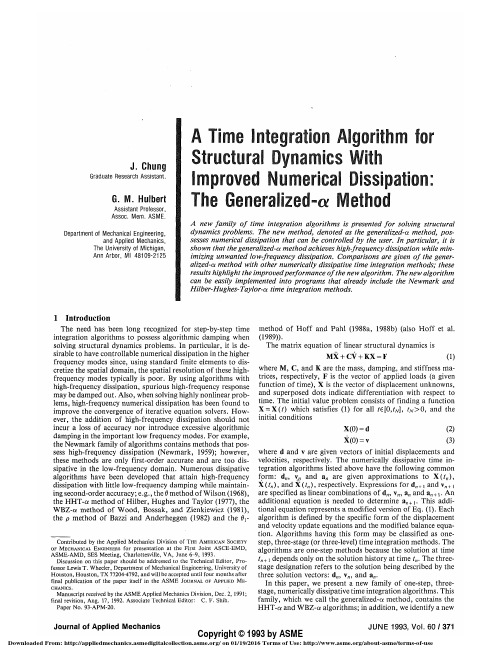
where d and v are given vectors of initial displacements and velocities, respectively. The numerically dissipative time integration algorithms listed above have the following common form: d„, Vj, and a„ are given approximations to X(?„), X(^„), and X(t„), respectively. Expressions for d„ + , and v„ +) are specified as linear combinations of d,„ v„, a„ and a„ + i. An additional equation is needed to determine a„+1. This additional equation represents a modified version of Eq. (1). Each algorithm is defined by the specific form of the displacement and velocity update equations and the modified balance equation. Algorithms having this form may be classified as onestep, three-stage (or three-level) time integration methods. The algorithms are one-step methods because the solution at time t„+i depends only on the solution history at time t„. The threestage designation refers to the solution being described by the three solution vectors: d„, v„, and a„. In this paper, we present a new family of one-step, threestage, numerically dissipative time integration algorithms. This family, which we call the generalized-a method, contains the HHT-a and WBZ-a algorithms; in addition, we identify a new
动态负载平衡

一部分都对应着这条有序的曲线上的一个点从而实现了二维向一维的转
换。在三维空间上也可以得到这样的结果。
26
5.4优化的局限 引入填充曲线的方法并不是万能的,它有两个很重要的基础。第一个就 是每个等级的节点数量必须足够多这样在同等级的节点内部就可以达到 负载平衡这样就不用和别等级的节点进行信息传递。第二个就是节点与 节点之间的交通足够发达。
3.动态负载平衡算法
流程图:
开始
初始化 S[ ]=0,W[ ]=0 S[s]=l W[s]=k-A[s]
A[l]=A[l]-W[s]
s=1
l=min{ j | A[j] >k}
A[l]<k Y l=l+1 Y s=s+1
N
l>s N 结束
12
4.理论分析
现在来分析算法迁移过程的性能,这里定义了一 些性能度量标准,给出了本算法相对最佳解决方案 的近似率。结果如下表:
江林刚 谢劲
1
内容提要
Introduction Related work
动态负载平衡的算法 算法的分析 结论
2
1.Introduction
Quantum Monte Carlo(QMC): 一类基于量子力学的计算电子结构的算法。 通过直接处理量子力学的多体问题, 精确度比密度 泛函理论( DFT)这些方法要高,但是计算量大很 多。 可用于并行机上,DFT不能用于并行机上。
27
6 结论
我们已经提出了一个新的针对大量独立相同工作计算的负载平
衡算法,这个算法有一些很好的理论性能。我们用实例测试证实了 它比现有的用于量子蒙特卡罗方法代码运作更好。我们也优化了它 的实现,并证明了它由于减少网络争用而性能优良。算法的相关性 能被期待能进一步提高,这需要未来机器上剧增的处理单元的数量。
120厚钢筋桁架楼承板技术参数表

120厚钢筋桁架楼承板技术参数表The technical parameters of the 120 thick steel bar truss floor slab are essential for understanding the structural capabilities and limitations of this particular building component. These parameters provide valuable information for engineers, architects, and construction professionals involved in the design and construction of buildings. Understanding the technical specifications of the 120 thick steel bar truss floor slab is crucial for ensuring the safety, stability, and performance of the structure. Therefore, it is important to delve into the various aspects of the technical parameters to gain a comprehensive understanding of this critical building element.First and foremost, the material composition of the 120 thick steel bar truss floor slab is a key technical parameter. The type of steel used, its grade, and its physical properties have a significant impact on the strength, durability, and load-bearing capacity of thefloor slab. Engineers and construction professionals must carefully consider the material composition to ensure that it meets the structural requirements and performance standards for the intended application. Additionally, the material composition plays a crucial role in determining the overall quality and longevity of the floor slab, making it a fundamental aspect of the technical parameters.Another important technical parameter of the 120 thick steel bar truss floor slab is its dimensions and geometry. The size, shape, and configuration of the floor slab directly influence its structural behavior, weight-bearing capacity, and compatibility with other building components. Engineers and architects must carefully consider the dimensions and geometry of the floor slab to ensure that it aligns with the overall design and construction requirements. Moreover, these technical parameters are essential for determining the installation, support, and connection methods for the floor slab, making them critical for the successful integration of the component within the building structure.In addition to material composition and dimensions, the load-bearing capacity of the 120 thick steel bar trussfloor slab is a crucial technical parameter that requires careful consideration. The ability of the floor slab to support various loads, including live loads, dead loads, and dynamic loads, is essential for ensuring the safety and stability of the structure. Engineers must accurately assess and calculate the load-bearing capacity of the floor slab to prevent overloading and structural failure. Moreover, understanding this technical parameter is vital for determining the appropriate design and construction considerations to enhance the overall performance and reliability of the floor slab.Furthermore, the fire resistance and thermal properties of the 120 thick steel bar truss floor slab are important technical parameters that warrant attention. The ability of the floor slab to withstand fire exposure and maintain its structural integrity is critical for ensuring the safety and protection of building occupants. Additionally, the thermal properties of the floor slab influence its insulation capabilities and energy efficiency, making themessential considerations for sustainable and resilient building design. Engineers and construction professionals must carefully evaluate these technical parameters to implement appropriate fire protection measures and optimize the thermal performance of the floor slab.Moreover, the corrosion resistance and maintenance requirements of the 120 thick steel bar truss floor slab are significant technical parameters that impact its long-term durability and performance. The potential for corrosion due to environmental exposure, moisture, and chemical agents can compromise the structural integrity and service life of the floor slab. Therefore, engineers and construction professionals must select materials and coatings that offer superior corrosion resistance to mitigate these risks. Additionally, understanding the maintenance requirements of the floor slab is essential for developing effective maintenance plans and preserving its structural and functional properties over time.In conclusion, the technical parameters of the 120thick steel bar truss floor slab are critical forunderstanding its material composition, dimensions, load-bearing capacity, fire resistance, thermal properties, corrosion resistance, and maintenance requirements. These parameters provide valuable insights for engineers, architects, and construction professionals involved in the design and construction of buildings. By carefully evaluating and addressing these technical parameters, stakeholders can ensure the safety, stability, and performance of the floor slab within the building structure. Therefore, a comprehensive understanding of the technical specifications is essential for making informed decisions and implementing effective design and construction practices.。
2020年9月英语六级真题及参考答案完整版

2020年9月英语六级真题及参考答案【完整版】四六级试卷采用多题多卷形式,大家核对答案时,请找具体选项内容,忽略套数。
无忧考网搜集整理了各个版本(有文字也有图片),仅供大家参考。
【网络综合版】听力:Section ALong Conversation OneM: You are a professor of Physics at the University of Oxford. You are a senior advisor at the European Organization for Nuclear Research. You also seem to tour the global tirelessly, giving talks. And in addition, you have your own weekly TV show On Science. Where do you get the energy?W: Oh, well. 【Q1】I just love what I do. I am extremely fortunate to have this life, doing what I love doing.M: Professor, what exactly is your goal? Why do you do all of these?W: well, as you said, I do have different things going on. But these I think can be divided into 【Q2】two groups: the education of science, and the further understanding of science.M: Don't these two things get in the way of each other? What I mean is, doesn't giving lectures take time away from the lab?W: Not really, no. I love teaching, and I don’t mind spending more time doing that now than in the past. Also, what I will say is, that 【Q3】teaching a subject helps me comprehend it better myself. I find that it furthers my own knowledge when I have to explain something clearly, when I have to aid others understanding it, and when I have to answer questions about it. Teaching at a high level can be very stimulating for anyone, no matter how much expertise they may already have in the field they are instructing.M: Are there any scientific breakthroughs that you see on the near horizon? A significant discovery or invention we can expect soon.W: 【Q4】The world is always conducting science. And there're constantly new things being discovered. In fact, right now, we have too much data sitting in computers.For example, we have thousands of photos of planet Mars taken by telescopes that nobody has ever seen. We have them, yet nobody has had time to look at them with their own eyes, let alone analyze them.Q1: Why does the woman say she can be so energetic?Q2: What has the woman been engaged in?Q3: What does the woman say about the benefit teaching brings to her?Q4: How does the woman say new scientific breakthroughs can be made possible?Section AConversation 2M: Do you think dreams 【Q5】have special meanings?W: No. I don't think they do.M: I don't either, but some people do. I would say people who believe that dreams have special meanings are superstitious, especially nowadays. In the past, during the times of ancient Egypt, Greece or China, people used to believe that dreams could foresee the future. But today, with all the scientific knowledge that we have, I think it's much harder to believe in these sorts of things.W: My grandmother is superstitious, and she thinks dreams can predict the future. Once, 【Q6】she dreamed that the flight she was due to take the following day crashed.Can you guess what she did? She didn't take that flight. She didn't even bother to go to the airport the following day. Instead, she took the same flight but a week later. And everything was fine of course. No plane ever crashed.M: How funny! Did you know that flying is actually safer than any other mode of transport? It's been statistically proven. People can be so irrational sometimes.W: Yes, absolutely. But, even if we think they are ridiculous, 【Q7】emotions can be just as powerful as rational thinking.M: Exactly. People do all sorts of crazy things because of their irrational feelings. But in fact, some psychologists believe that our dreams are the result of our emotions and memories from that day. I think it was Sigmund Freud who said that children's dreams were usually simple representations of their wishes, thingsthey wished would happen. 【Q8】But in adults', dreams are much more complicated reflections of their more sophisticated sentiments.W: Isn't it interesting how psychologists try to understand using the scientific method something as bazaar as dreams? Psychology is like the rational study of irrational feelings.Q5: What do both speakers think of dreams?Q6: Why didn't the woman's grandmother take her scheduled flight?Q7: What does the woman say about people's emotions?Q8: What did psychologist Sigmund Freud say about adults' dreams?Section BPassage 1While some scientists explore the surface of the Antarctic, others are learning more about a giant body of water -- four kilometers beneath the ice pack. Scientists first discovered Lake Vostok in the 1970s by using radio waves that penetrate the ice. Since then, they have used sound waves and even satellites to map this massive body of water. How does the water in Lake Vostok remained liquid beneath an ice sheet? “The thick glacier above acts like insulating blanket and keeps the water from freezing,” said Martin Siegert, a glaciologist from the university of Wales. In addition, geothermal heat from the deep within the earth may warm the hidden lake.The scientists suspect that microorganisms may be living in Lake Vostok, closed or more than two million years. Anything found that off from the outside world f s on the surface of the earth, said Siegert. Scientists ’will be totally alien to what are trying to find a way to drill into the ice and draw water samples without causing ht be the solution. If all goes as planned, a contamination. Again, robots mig shift robot will melt through the surface ice. When it reaches the lake, it -drill will release another robot that can swim in the lake, take pictures and look for ries will shed light on life in outer signs of life. The scientists hope that discove up -space, which might exist in similar dark and airless conditions. Recently closed s moon, Europa, shows signs of water beneath the icy surface. ’pictures of Jupiter ropa to search for life there, Once tested the Antarctic, robots could be set to Eu too.Q9: What did the scientists first use to discover Lake Vostok in the 1970s? Q10: What did scientists think about Lake Vostok?Q11: What do the scientists hope their discoveries will do?Section BPassage 2The idea to study the American Indian tribe – Tarahumaras, came to James Copeland in 1984 when 【Q12】he discovered that very little research had been done on their language. He contacted the tribe member through a social worker who workedwith the tribes in Mexico. At first, the tribe member named Gonzalez was very reluctant to cooperate. He told Copeland that no amount of money could buy his language. But after Copeland explained to him what he intended to do with his research and how it would benefit the Tarahumaras, Gonzalez agreed to help. 【Q13】He took Copeland to his village and served as an intermediary. Copeland says, thanks to him, the Tarahumaras understood what their mission was and started trusting us. 【Q14】Entering the world of Tarahumaras has been a laborious project for Copeland.To reach their homeland, he must strive two and half days from Huston Taxes. He loads up his vehicle with goods that the tribe’s men can’t easily get and gives the goods to them as a gesture of friendship. The Tarahumaras, who don’t believe any humiliating wealth, take the food and share among themselves. For Copeland, the experience has not only been academically satisfying but also has enriched his life in several ways. 【Q15】“I see people rejecting technology and living a very hard, traditional life, which offers me another notion about the meaning of progress in the western tradition,” he says, “I experienced the simplicity of living in nature that I would otherwise only be able to read about.I see a lot of beauty and their sense of sharing and concern for each other.”Q12: Why did James Copeland want to study the American Indian tribe -- Tarahumaras?Q13: How did Gonzalez help James Copeland?Q14: What does the speaker say about James Copeland’s trip to the Tarahumaras village?Q15: What impresses James Copeland about the Tarahumaras tribe?Section CRecording 1What is a radical? It seems today that people are terrified of the term,minority, who are mostly wealthy white males in western society.Feminism is a perfect example of this phenomenon. The women's movement has been plagued by stereotypes, misrepresentations by the media, and accusations of man-hating and radicalism. When the basic foundation of feminism is simply that women deserve equal rights in all facets of life. When faced with the threat of being labelled radical, women back down from their worthy calls and consequently, participate in their own oppression.It has gotten to the point that many women are afraid to call themselves feminists because of a stigma attached to the word. If people refused to be controlled, and intimidated by stigmas, the stigmas lose all their power, without fear on which they feed, such stigmas can only die.To me, 【Q17】a radical is simply someone who rebels against the norm when advocates a change in the existing state of affairs. On close inspection, it becomes clear that the norm is constantly involving, and therefore, is not a constant entity. So why then, is deviation from the present situation such a threat, when the state of affairs itself is unstable and subject to relentless transformation?It all goes back to maintaining the power of those who have it and preventing the right of those who don't. In fact, when we look at the word "radical" in a historical context, nearly every figure we now hold up as a hero was considered a radical in his or her time. Radicals are people who affect change. They are the people about whom history is written. Abolitionists were radicals, civil rights activists were radicals, 【Q18】 even the founders of our country in their fight to win independence from England were radicals. Their presence in history has changed the way our society functions, mainly by shifting the balance of power that previously existed. Of course, there are some radicals who've made a negative impact on humanity, 【Q18】 but undeniably, there would simply be no progress without radicals. That been said, next time someone calls me a radical, I would accept that label with pride.Q16: What usually happens when people are accused of being radical?Q17: What is the speaker's definition of a radical?Q18: What does the speaker think of most radicals in the American history?Recording 2We are very susceptible to the influence of the people around us. For instance, you may have known somebody who has gone overseas for a year or so and has returned with an accent perhaps. We become part of our immediate environment. None of us are immune to the influences of our own world and let us not kid ourselves that we are untouched by the things and people in our life.Fred goes off to his new job at a factory. Fred takes his ten-minute coffee break, but the other workers take half an hour. Fred says, “What’s the matter with you guys?” Two weeks later, Fred is taking twenty-minute breaks. A month later, Fred takes his half hour. Fred is saying “If you can’t be them, join them. Why should I work any harder than the next guy?” The fascinating thing about being human is that generally we are unaware that there are changes taking place in our mentality. It is like returning to the city smog after some weeks in the fresh air. Only then do we realize that we’ve become accustomed to the nasty smells. Mix with critical people and we learn to criticize. Mix with happy people, and we learn about happiness. What this means is that we need to decide what we want from life and then choose our company accordingly. You may well say, "That is going to take some effort. It may not be comfortable. I may offend some of my present company." Right, but it is your life. Fred may say, "I’m always broke, frequently depressed. I’m going nowhereand I never do anything exciting." Then we discover that Fred’s best friends are always broke, frequently depressed, going nowhere and wishing that life was more exciting. This is not coincidence, nor is it our business to stand in judgement of Fred? However, if Fred ever wants to improve his quality of life, the first thing he'll need to do is recognize what has been going on all these years.It’s no surprise that doctors as a profession suffer a lot of ill health, because they spend their life around sick people. Psychiatrists have a higher incidence of suicide in their profession for related reasons. Traditionally, nine out of ten children whose parents smoke, smoke themselves. Obesity is in part an environmental problem. Successful people have successful friends, and so the story goes on.Q19 What does the speaker say about us as human beings?Q20 What does the speaker say Fred should do first to improve his quality of life?Q21 What does the speaker say about the psychiatrists?Section CLecture 3Virtually every American can recognize a dollar bill at a mere glance. Many can identify it by its sound or texture. But 【Q22】few people indeed can accurately describe the world's most powerful, important currency.The American dollar bill is colored with black ink on one side and green on the other;【Q23】 the exact composition of the paper and ink is a closely guarded government secret. Despite its weighty importance, the dollar bill actually weighs little. It requires nearly 500 bills to tip the scales at a pound. Not only is the dollar bill lightweight, but it also has a brief life span. Few dollar bills survive longer than 18 months.The word "dollar" is taken from the German word "taler," the name for the world's most important currency in the 16th century. The taler was a silver coin first minted in 1518 under the reign of Charles V, Emperor of Germany.The concept of paper money is a relatively recent innovation in the history of American currency. When the Constitution was signed, people had little regard for paper money because of its steadily decreasing value during the colonial era.【Q24】Because of this lack of faith, the new American government minted only coins for common currency. Interest-bearing bank notes were issued at the same time, but their purpose was limited to providing money for urgent government crises, such as American involvement in the War of 1812.The first noninterest-bearing paper currency was authorized by Congress in 1862, at the height of the Civil War. At this point, citizens' old fears of devalued paper currency had calmed, and the dollar bill was born. The new green colored paper money quickly earned the nickname "greenback."Today, the American dollar bill is a product of the Federal Reserve and is issued from the twelve Federal Reserve banks around the United States. The government keeps a steady supply of approximately two billion bills in circulation at all times.Controversy continues to surround the true value of the dollar bill.【Q25】American history has seen generations of politicians argue in favor of a gold standard for American currency. However, for the present, the American dollar bill holds the value that is printed on it, and little more. The only other guarantee on the bill is a Federal Reserve pledge of as a confirmation in the form of government securities.Q22: What does the speaker say about the American dollar bill?Q23: What does the speaker say about the exact composition of the American dollar bill?Q24: Why did the new American government mint only coins for common currency?Q25: What have generations of American politicians argued for?参考答案1.A)She can devote all her life to pursing her passion.2.D)Science education and scientific research.3.A)A better understanding of a subject.4.B)By making full use of the existing data.5. B) They have no special meanings.6. C) She dreamed of a plane crash.7. D) They can have an impact as great as rational thinking8. C) They reflect their complicated emotions.9. A) Radio waves.10. B)It may have micro—organisms living in it.11. D)Shed light on possible life in outer space.12. A)He found there had been little research on their anguage.13. D)He acted as an intermediary between Copel and the villagers.14. C)Laborious15. B)Their sense of sharing and caring.16 .A)They tend to be silenced into submission.17. D)One who rebels against the existing social orser.18. C)They served as a driving force for progress.19. B)It is impossible for us to be immune from outside influence.20. D) Recognize the negative impact of his coworkers.21. A) They are quite susceptible to suicide.22. B) Few people can describe it precisely.23. C) It is a well—protected government secret.24. A) People had little faith in paper money.25. C) It is awell—protected government secret.翻译:《水浒传》(Water Margin)是中国文学四大经典小说之一。
DYNAMICSOFSTRUCTURES

Generalized Displacement This procedure is based on the assumption that the deflected shape of the structure can be expressed as the sum of a series of(一系列) specified displacement patterns(位移模式); these patterns then become the displacement coordinates of the structure.
In general, any arbitrary shape compatible with the prescribed support conditions(约束条件) of the simple beam can be represented by this infinite series of sine-wave components. This concept can be further generalized by recognizing that the sine-wave shapes used as the assumed displacement patterns were an arbitrary choice in this example. Thus a generalized expression for the displacements of any onedimensional structure might be written
The term dynamic may be defined simply as timevarying(时变); thus a dynamic load is any load of which its magnitude(幅值), direction, and/or position varies with time. Similarly, the structural response(响应) to a dynamic load is also time-varying, or dynamic.
西门子Solid Edge模拟软件说明说明书

SummarySiemens Solid Edge® Simulation software is an easy-to-use, built-in finite element analysis (FEA) tool that enables design engineers to digitally validate part and assembly designs within the Solid Edge environment. Based on proven Simcenter Femap™ finite element modeling tech-nology, Solid Edge Simulation signifi-cantly reduces the need for physicalprototypes, reducing material and testing costs, while saving design time.For use by design engineersSolid Edge Simulation uses the same underlying geometry and user interface as all Solid Edge applications. It’s easy enough for any Solid Edge user with a fundamental understanding of FEA prin-ciples, yet robust enough to service almost any analysis need. By enabling engineers to perform their own simula-tion, more analysis can be performed in less time — improving quality, reducing material costs and minimizing the need for physical prototypes — without incurring the high costs of outsourced analysis. The layout of the user inter-face is designed to guide the user through the entire analysis process, with help available if needed, which makes it easy to learn initially, andrevisit if necessary./en/solutions/products/simulationBenefits• Innovate more by experimenting with designs virtually • Optimize material usage and minimize product weight • Reduce the need for costly prototypes with virtual testing • Get products to market faster with reduced physical testing • Reduce recalls by finding out if products fail before it reaches the customer • Execute redesigns faster with synchronous technology Features• Embedded finite element analysis for design engineers • Automatic finite element model creation with optional manual override • Realistic operating environment modeling with full complement of loads and constraint definitions • Evaluate designs for deformation, stress, resonant frequencies, buck-ling, heat transfer thermal stress and vibration response • Ability to maintain loads and con-straints during model changesSolid Edge SimulationEmbedded finite element analysis for design engineersSolid Edge SimulationFeatures continued• Import fluid pressure and tempera-ture results from Simcenter FLOEFD for Solid Edge • Embedded advanced motion simulationAutomatic finite element model creationSolid Edge Simulation supports solid meshes (using tetrahedral elements), two-dimensional shell element meshes on mid-surfaced sheet structures, hybrid models that contain both 2D shell and 3D solid elements, as well as 1D beam elements for frame structures. Users can create and refine finite ele-ment meshes where required to improve accuracy of results.A mesh size slider bar that makes ele-ment size adjustments to the overall finite element mesh is available with additional control of the number of ele-ments on individual edges and faces. With Solid Edge Simulation, you can leverage a mapped mesh capability to take advantage of certain geometry topologies and create a more orderly and well-shaped mesh. In addition, the mesh size will automatically adjust to accommodate detailed model features. You can fine-tune the mesh with man-ual edge and face element sizing to generate an efficient simulation model that will deliver accurate results. Prior to creating the finite element model, you can prepare and simplify the geom-etry model quickly and easily with syn-chronous technology and its ability to make history-free model changes. Solid Edge synchronous technology combines the speed and simplicity of direct mod-eling with the flexibility and control of parametric design.Full complement of load and constraint definitionsSolid Edge Simulation provides allboundary condition definitions needed to define realistic operating environ-ments. The constraints are geometry-based and include fixed, pinned, norotation, symmetric and cylindrical vari-ations. The loads are also geometry-based and include mechanical as well as temperature loading for thermal analy-ses. Mechanical loads include forces, pressures and effects caused by body rotation and gravity. Solid Edge Simulation facilitates load and con-straint applications with Quick Bar input options and handles for direction and orientation definition.Analyzing assembliesAssembly model components can quickly be connected, and interaction can be a glued connection between components or surface contacts based on an iterative linear solution.Contact between components can be detected automatically, or connectors can be defined individually through man-ual face selection. Assembly materials and properties can be applied manually, selected from a material library or inher-ited from the geometry model by default. The included Simcenter™ Nastran® solver assures realistic assembly/component interaction to facilitate robust solutions.Solid Edge Simulation offers complete control of the management of geome-tries in a simulation study. Components can easily be suppressed or removed from a study to maximize efficiency, improving user experience.Analysis typesUsing the industry-standard Simcenter Nastran solver, Solid Edge Simulation delivers structural simulation results, such as deformation, stress and strain, etc. caused by a static loading, finding the natural frequencies of vibration or determining buckling loads of a design. Both steady and transient heat transfer analysis validate cooling performance by evaluating the temperature distribu-tion of the model. In addition, the cou-pled thermal and structural analysis can be applied to determine thermal effects to the structural stress/strain.Fluid pressure and temperature results can be imported from Simcenter FLOEFD™ for Solid Edge as structural loads for analysis. FLOEFD for Solid Edge delivers the industry’s leading computational fluid dynamics (CFD) analysis tool for fluid flow and heat transfer. Integration between the two simulation solutions is seamless and easy, as both are fully embedded in the Solid Edge environment.Harmonic response analysis, dynamic response analysis in frequency domain, is also available to simulate the actual vibration level. Re-use of finite element model loads and constraints is as easy as dragging and dropping from one study to another.Designs in motionWith dynamic motion simulation, Solid Edge Simulation allows you to evaluate and visualize how parts will interact in an assembly. The easy-to-use solution simulates how a product will perform throughout its operational cycle, allow-ing you to see how it would function in the real world and measure the forces and loads on the design.Solid Edge Simulation offers you the ability to create motion models from existing Solid Edge assemblies.Mechanical joints can easily be created by either automatically converting them from assembly constraints, or by using the intuitive builder which walks you through the process step-by-step. Motion characteristics can then be added, including motors, actuators, gravity, realistic contact between bod-ies, springs, friction, damping and other generated forces as needed.Additionally, motion results, such as forces, can be utilized as load condi-tions for structural simulation.Scalable solutions for every user Powerful, scalable solution offerings allow you to select the best simulation tools for your individual requirements.Result evaluationSolid Edge Simulation allows you to inter-pret and understand the resulting model behavior quickly with comprehensive graphical result viewing tools. Simulation results can be displayed in various forms, including color and contour plots, which can be continuous, displayed as distinct contour bands or by element and dis-placement and mode shapes that can be animated. Minimum/maximum stress markers and a probe tool with results dis-plays are also available. The probe toolcan select nodes, faces and edges.With Solid Edge Simulation’s compre-hensive results evaluation functionality, you can quickly identify problem areas for potential design revision and gener-ate HTML reports of simulation model information and final results. Design updatesWith Solid Edge Simulation, you can quickly and easily make any required design update during post analysis. History-free, feature-based modelchanges with synchronous technologysignificantly accelerates the model+1 314 264 8499 © 2020 Siemens. A list of relevant Siemens trademarks can be found here . Other trademarks belong to their respective owners.78032-C9 6/20 Mrefinement process. In addition, Solid Edge Simulation maintains associativity between the CAD and finite element models, while making sure that applied loads and constraints are maintained for all geometry model changes.Analysis scalabilitySimulation functionality scales fromapplication to individual parts to analysis of large assemblies, all the way to Femap with Nastran, thereby enabling you to define and analyze complete systems. This complete line of products provides a scalable upgrade path for users who need to solve more challenging engi-neering problems. Complete geometry and finite element models with bound-ary conditions and results can be seam-lessly transferred from Solid Edge to Femap, where more advanced analyses can be employed if desired.Extending valueSolid Edge is a portfolio of affordable, easy to deploy, maintain and use soft-ware tools that advance all aspects of the product development process -- mechanical and electrical design, simu-lation, manufacturing, technicaldocumentation, data management and cloud-based collaboration. Minimum system configuration • Windows 10 Enterprise orProfessional (64-bit only) version 1809 or later • 16 GB RAM • 65K colors• Screen resolution: 1920 x 1080• 8.5 GB of disk space required for installation。
机械类专业英文翻译
Design of machine and machine elementsMachine designMachine design is the art of planning or devising new or improved machines to accomplish specific purposes. In general, a machine will consist of a combination of several different mechanical elements properly designed and arranged to work together, as a whole. During the initial planning of a machine, fundamental decisions must be made concerning loading, type of kinematic elements to be used, and correct utilization of the properties of engineering materials. Economic considerations are usually of prime importance when the design of new machinery is undertaken. In general, the lowest over-all costs are designed. Consideration should be given not only to the cost of design, manufacture the necessary safety features and be of pleasing external appearance. The objective is to produce a machine which is not only sufficiently rugged to function properly for a reasonable life, but is at the same time cheap enough to be economically feasible.The engineer in charge of the design of a machine should not only have adequate technical training, but must be a man of sound judgment and wide experience, qualities which are usually acquired only after considerable time has been spent in actual professional work.Design of machine elementsThe principles of design are, of course, universal. The same theory or equations may be applied to a very small part, as in an instrument, or, to a larger but similar part used in a piece of heavy equipment. In no ease, however, sho uld mathematical calculations be looked upon as absolute and final. They are all subject to the accuracy of the various assumptions, which must necessarily be made in engineering work. Sometimes only a portion of the total number of parts in a machine are designed on the basis of analytic calculations. The form and size of the remaining parts are designed on the basis of analytic calculations. On the other hand, if the machine is very expensive, or if weight is a factor, as in airplanes, design computations may then be made for almost all the parts.The purpose of the design calculations is, of course, to attempt to predict thestress or deformation in the part in order that it may sagely carry the loads, which will be imposed on it, and that it may last for the expected life of the machine. All calculations are, of course, dependent on the physical properties of the construction materials as determined by laboratory tests. A rational method of design attempts to take the results of relatively simple and fundamental tests such as tension, compression, torsion, and fatigue and apply them to all the complicated and involved situations encountered in present-day machinery.In addition, it has been amply proved that such details as surface condition, fillets, notches, manufacturing tolerances, and heat treatment have a market effect on the strength and useful life of a machine part. The design and drafting departments must specify completely all such particulars, must specify completely all such particulars, and thus exercise the necessary close control over the finished product.As mentioned above, machine design is a vast field of engineering technology. As such, it begins with the conception of an idea and follows through the various phases of design analysis, manufacturing, marketing and consumerism. The following is a list of the major areas of consideration in the general field of machine design:①Initial design conception;②Strength analysis;③Materials selection;④Appearance;⑤Manufacturing;⑥Safety;⑦Environment effects;⑨Reliability and life;Strength is a measure of the ability to resist, without fails, forces which cause stresses and strains. The forces may be;①Gradually applied;②Suddenly applied;③Applied under impact;④Applied with continuous direction reversals;⑤Applied at low or elevated temperatures.If a critical part of a machine fails, the whole machine must be shut down until a repair is made. Thus, when designing a new machine, it is extremely important that critical parts be made strong enough to prevent failure. The designer should determine as precisely as possible the nature, magnitude, direction and point of application of all forces. Machine design is mot, however, an exact science and it is, therefore, rarely possible to determine exactly all the applied forces. In addition, different samples of a specified material will exhibit somewhat different abilities to resist loads, temperatures and other environment conditions. In spite of this, design calculations based on appropriate assumptions are invaluable in the proper design of machine.Moreover, it is absolutely essential that a design engineer knows how and why parts fail so that reliable machines which require minimum maintenance can be designed. Sometimes, a failure can be serious, such as when a tire blows out on an automobile traveling at high speeds. On the other hand, a failure may be no more than a nuisance. An example is the loosening of the radiator hose in the automobile cooling system. The consequence of this latter failure is usually the loss of some radiator coolant, a condition which is readily detected and corrected.The type of load a part absorbs is just as significant as the magnitude. Generally speaking, dynamic loads with direction reversals cause greater difficulties than static loads and, therefore, fatigue strength must be considered. Another concern is whether the material is ductile or brittle. For example, brittle materials are considered to be unacceptable where fatigue is involved.In general, the design engineer must consider all possible modes of failure, which include the following:①Stress;②Deformation;③Wear;④Corrosion;⑤Vibration;⑥Environmental damage;⑦Loosening of fastening devices.The part sizes and shapes selected must also take into account many dimensional factors which produce external load effects such as geometric discontinuities, residual stresses due to forming of desired contours, and the application of interference fit joint.Selected from” design of machine elements”, 6th edition, m. f. sports, prentice-hall, inc., 1985 and “machine design”, Anthony Esposito, charles e., Merrill publishing company, 1975.Mechanical properties of materialsThe material properties can be classified into three major headings: (1) physical, (2) chemical, (3) mechanicalPhysical propertiesDensity or specific gravity, moisture content, etc., can be classified under this category.Chemical propertiesMany chemical properties come under this category. These include acidity or alkalinity, react6ivity and corrosion. The most important of these is corrosion which can be explained in layman’s terms as the resistance of the material to decay while in continuous use in a particular atmosphere.Mechanical propertiesMechanical properties include in the strength properties like tensile, compression, shear, torsion, impact, fatigue and creep. The tensile strength of a material is obtained by dividing the maximum load, which the specimen bears by the area of cross-section of the specimen.This is a curve plotted between the stress along the This is a curve plotted between the stress along the Y-axis(ordinate) and the strain along the X-axis (abscissa) in a tensile test. A material tends to change or changes its dimensionswhen it is loaded, depending upon the magnitude of the load. When the load is removed it can be seen that the deformation disappears. For many materials this occurs op to a certain value of the stress called the elastic limit Ap. This is depicted by the straight line relationship and a small deviation thereafter, in the stress-strain curve (fig.3.1). Within the elastic range, the limiting value of the stress up to which the stress and strain are proportional, is called the limit of proportionality Ap. In this region, the metal obeys hookes’s law, which states that the stress is proportional to strain in the elastic range of loading, (the material completely regains its original dimensions after the load is removed). In the actual plotting of the curve, the proportionality limit is obtained at a slightly lower value of the load than theelastic limit. This may be attributed to the time-lagin the regaining of the original dimensions of the material. This effect is very frequently noticed in some non-ferrous metals.Which iron and nickel exhibit clear ranges of elasticity, copper, zinc, tin, are found to be imperfectly elastic even at relatively low values low values of stresses. Actually the elastic limit is distinguishable from the proportionality limit more clearly depending upon the sensitivity of the measuring instrument. When the load is increased beyond the elastic limit, plastic deformation starts.Simultaneously the specimen gets work-hardened. A point is reached when the deformation starts to occur more rapidly than the increasing load. This point is called they yield point Q. the metal which was resisting the load till then, starts to deform somewhat rapidly, i. e., yield. The yield stress is called yield limit Ay. The elongation of the specimen continues from Q to S and then to T. The stress-strain relation in this plastic flow period is indicated by the portion QRST of the curve. At the specimen breaks, and this load is called the breaking load. The value of the maximum load S divided by the original cross-sectional area of the specimen is referred to as the ultimate tensile strength of the metal or simply the tensile strength Au.Logically speaking, once the elastic limit is exceeded, the metal should start to yield, and finally break, without any increase in the value of stress. But the curve records an increased stress even after the elastic limit is exceeded. Two reasons can be given for this behavior:①The strain hardening of the material;②The diminishing cross-sectional area of the specimen, suffered on account of the plastic deformation.The more plastic deformation the metal undergoes, the harder it becomes, due to work-hardening. The more the metal gets elongated the more its diameter (and hence, cross-sectional area) is decreased. This continues until the point S is reached.After S, the rate at which the reduction in area takes place, exceeds the rate at which the stress increases. Strain becomes so high that the reduction in area begins to produce a localized effect at some point. This is called necking. Reduction in cross-sectional area takes place very rapidly; so rapidly that the load value actually drops. This is indicated by ST. failure occurs at this point T. Then percentage elongation A and reduction in reduction in area W indicate the ductility or plasticity of the material:A=(L-L0)/L0*100%W=(A0-A)/A0*100%Where L0 and L are the original and the final length of the specimen; A0 and A are the original and the final cross-section area.Selected from “testing of metallic materials”Quality assurance and controlProduct quality is of paramount importance in manufacturing. If quality is allowed deteriorate, then a manufacturer will soon find sales dropping off followed by a possible business failure. Customers expect quality in the products they buy, and if a manufacturer expects to establish and maintain a name in the business, quality control and assurance functions must be established and maintained before, throughout, and after the production process. Generally speaking, quality assurance encompasses all activities aimed at maintaining quality, including quality control. Quality assurance can be divided into three major areas. These include the following:①Source and receiving inspection before manufacturing;②In-process quality control during manufacturing;③Quality assurance after manufacturing.Quality control after manufacture includes warranties and product service extended to the users of the product.Source and receiving inspection before manufacturingQuality assurance often begins ling before any actual manufacturing takes place. This may be done through source inspections conducted at the plants that supply materials, discrete parts, or subassemblies to manufacturer. The manufacturer’s source inspector travels to the supplier factory and inspects raw material or premanufactured parts and assemblies. Source inspections present an opportunity for the manufacturer to sort out and reject raw materials or parts before they are shipped to the manufacturer’s production facility.The responsibility of the source inspector is to check materials and parts against design specifications and to reject the item if specifications are not met. Source inspections may include many of the same inspections that will be used during production. Included in these are:①Visual inspection;②Metallurgical testing;③Dimensional inspection;④Destructive and nondestructive inspection;⑤Performance inspection.Visual inspectionsVisual inspections examine a product or material for such specifications as color, texture, surface finish, or overall appearance of an assembly to determine if there are any obvious deletions of major parts or hardware.Metallurgical testingMetallurgical testing is often an important part of source inspection, especiallyif the primary raw material for manufacturing is stock metal such as bar stock or structural materials. Metals testing can involve all the major types of inspections including visual, chemical, spectrographic, and mechanical, which include hardness, tensile, shear, compression, and spectr5ographic analysis for alloy content. Metallurgical testing can be either destructive or nondestructive. Dimensional inspectionFew areas of quality control are as important in manufactured products as dimensional requirements. Dimensions are as important in source inspection as they are in the manufacturing process. This is especially critical if the source supplies parts for an assembly. Dimensions are inspected at the source factory using standard measuring tools plus special fit, form, and function gages that may required. Meeting dimensional specifications is critical to interchangeabilityof manufactured parts and to the successful assembly of many parts into complex assemblies such as autos, ships, aircraft, and other multipart products. Destructive and nondestructive inspectionIn some cases it may be necessary for the source inspections to call for destructive or nondestructive tests on raw materials or p0arts and assemblies. This is particularly true when large amounts of stock raw materials are involved. For example it may be necessary to inspect castings for flaws by radiographic,magnetic particle, or dye penetrant techniques before they are shipped to the manufacturer for final machining. Specifications calling for burn-in time for electronics or endurance run tests for mechanical components are further examples of nondestructive tests.It is sometimes necessary to test material and parts to destruction, but because of the costs and time involved destructive testing is avoided whenever possible. Examples include pressure tests to determine if safety factors are adequate in the design. Destructive tests are probably more frequent in the testing of prototype designs than in routine inspection of raw material or parts. Once design specifications are known to be met in regard to the strength of materials, it is often not necessary to test further parts to destruction unless they are genuinely suspect.Performance inspectionPerformance inspections involve checking the function of assemblies, especially those of complex mechanical systems, prior to installation in other products. Examples include electronic equipment subcomponents, aircraft and auto engines, pumps, valves, and other mechanical systems requiring performance evaluation prior to their shipment and final installation.Selected form “modern materials and manufacturing process”Electro-hydraulic drum brakesApplicationThe YWW series electro-hydraulic brake is a normally closed brake, suitable for horizontal mounting. It is mainly used in portal cranes, bucket stacker/reclaimers’slewing mechanism.The YKW series electro-hydraulic brake is a normally opened brake, suitable for horizontal mounting, employing a thruster as actuator. with the foot controlling switch the operator can release or close the brake. It is mainly used for deceleration braking of portal cranes’slewing mechanism. In a non-operating state the machinery can be braked by a manual close device.The RKW series brake is a normally opened brake, which is operated by footdriven hydraulic pump, suitable for horizontal mounting. Mainly used in the slewing mechanism of middle and small portal cranes. When needed, the brakeis activated by a manual closed device.Main design featuresInterlocking shoes balancing devices (patented technology) constantly equalizes the clearance of brake shoes on both sides and made adjustment unnecessary, thus avoiding one side of the brake lining sticking to the brake wheel. The brake is equipped with a shoed autoaligning device.Main hinge points are equipped with self-lubricating bearing, making high efficiency of transmission, long service life. Lubricating is unnecessary during operation.Adjustable bracket ensure the brake works well.The brake spring is arranged inside a square tube and a surveyor’s rod is placed on one side. It is easy to read braking torque value and avoid measuring and computing.Brake lining is of card whole-piece shaping structure, easy to replace. Brake linings of various materials such as half-metal (non-asbestos) hard and half-hard, soft (including asbestos) substance are available for customers to choose.All adopt the company’s new types of thruster as corollary equipment which work accurately and have long life.Hydraulic Power TransmissionThe Two Types Of Power TransmissionIn hydraulic power transmission the apparatus (pump) used for conversion of the mechanical (or electrical,thermal) energy to hydraulic energy is arranged on the input of the kinematic chain ,and the apparatus (motor) used for conversion of the hydraulic energy to mechanical energy is arranged on the output (fig.2-1)The theoretical design of the energy converters depends on the component of the bernouilli equation to be used for hydraulic power transmission.In systerms where, mainly, hydrostatic pressure is utilized, displacement (hydrostatic) pumps and motors are used, while in those where the hydrodynamicpressure is utilized is utilized gor power transmission hydrodynamic energy converters (e.g. centrifugal pumps) are used.The specific characteristic of the energy converters is the weight required for transmission of unit power. It can be demonstrated that the use of hydrostatic energy converters for the low and medium powers, and of hydrodynamic energy converters of high power are more favorite (fig.2-2). This is the main reason why hydrostatic energy converters are used in industrial apparatus. transformation of the energy in hydraulic transmission.1.driving motor (electric, diesel engine);2.mechanical energy;3.pump;4.hydraulic energy;5.hydraulic motor;6.mechanical energy;7.load variation of the mass per unit power in hydrostatic and hydrodynamic energyconverters1、hydrostatic; 2.hydrodynamicOnly displacement energy converters are dealt with in the following.The elements performing converters provide one or several size. Expansion of the working chambers in a pump is produced by the external energy admitted, and in the motor by the hydraulic energy. Inflow of the fluid occurs during expansion of the working chamber, while the outflow (displacement) is realized during contraction.Such devices are usually called displacement energy converters.The Hydrostatic PowerIn order to have a fluid of volume V1 flowing in a vessel at pressure work spent on compression W1 and transfer of the process, let us imagine a piston mechanism (fig.2-3(a)) which may be connected with the aid of valves Z0 and Z1 to the external medium under pressure P0 and reservoir of pressure p1.in the upper position of the piston (x=x0) with Z0 open the cylinder chamber is filled with fluid of volume V0 and pressure P0. now shut the value Z0 and start the piston moving downwards. IfZ1 is shut the fluid volume in position X=X1 of the piston decreases from V0 to V1, while the pressure rises to P1. the external work required for actuation of the piston (assuming isothermal change) isW1=-∫0x0(P-P0)Adx=-∫v1v0(P-P0)dvSelect from Hydraulic Power Transmission机器和机器零件的设计机器设计机器设计为了特定的目的而发明或改进机器的一种艺术。
大跨度铁路悬索桥纵向位移特征及纵向支承要求
桥梁建设㊀2020年第50卷第4期(总第265期)BridgeConstructionꎬVol.50ꎬNo.4ꎬ2020(TotallyNo.265)文章编号:1003-4722(2020)04-0029-07大跨度铁路悬索桥纵向位移特征及纵向支承要求万田保ꎬ李松林(中铁大桥勘测设计院集团有限公司ꎬ湖北武汉430050)摘㊀要:为研究大跨度铁路悬索桥合理的纵向支承体系ꎬ从理论上分析大跨度悬索桥的刚度特性及大跨度铁路悬索桥的纵向位移特征ꎬ并以某主跨1060m上承式钢桁梁铁路悬索桥为例ꎬ分析大跨度铁路悬索桥在列车荷载作用下的梁端纵向位移特征ꎬ研究不同纵向支承体系对悬索桥加劲梁梁端纵向位移及速度的影响ꎬ最后给出大跨度铁路悬索桥纵向支承设计的要求ꎮ结果表明:竖向荷载作用下ꎬ结构产生显著纵向位移ꎬ是悬索桥的基本结构特征ꎻ竖向荷载作用在悬索桥加劲梁上不同位置时ꎬ加劲梁梁端纵向位移差别大ꎻ铁路列车作为快速移动荷载ꎬ具有规则㊁连续的特征ꎬ从而导致铁路悬索桥梁端频繁快速活动ꎬ此为梁端伸缩装置㊁支座㊁吊索耐久性的控制性因素ꎮ关键词:悬索桥ꎻ铁路桥ꎻ刚度特性ꎻ重力刚度ꎻ梁端纵向位移ꎻ纵向支承体系中图分类号:U448.25ꎻU441文献标志码:ALongitudinalDisplacementCharacteristicsandLongitudinalSupportingRequirementsforLong ̄SpanRailwaySuspensionBridgeWANTian ̄baoꎬLISong ̄lin(ChinaRailwayMajorBridgeReconnaissance&DesignInstituteCo.ꎬLtd.ꎬWuhan430050ꎬChina)Abstract:Thestiffnesspropertyandlongitudinaldisplacementcharacteristicsofthelong ̄spanrailwaysuspensionbridgearetheoreticallyanalyzedtofigureoutrationallongitudinalsupportingsystemsforthebridgeofthistype.Adeck ̄typesteeltrussgirderrailwaysuspensionbridgewithmainspanlengthof1060miscitedasanexample.Thecharacteristicsofgirder ̄endlongitudinaldisplacementsofthelong ̄spanrail ̄waysuspensionbridgeundertrainloadsareanalyzedꎬandtheinfluenceofdifferentlongitudinalsupportingsystemsonthegirder ̄endlongitudinaldisplacementandmovingspeedofthestiffeninggirderofsuspensionbridgeisstudiedandthedesignrequirementsoflongitudinalsupportsforlong ̄spanrailwaysuspensionbridgearegiven.Theresultsshowthatverticalloadscancauseevidentlongitudinaldisplacementinthesuspensionbridgeꎬwhichisconsideredthefundamentalstructuralcharacteristicsofsuspensionbridge.Whenverticalloadsactondifferentlocationsofthestiffeninggirderofsuspensionbridgeꎬthedifferencesofgirder ̄endlongitudinaldisplacementsarebig.Trainloadsarefastmovingloadsthatareregularandcontin ̄uousꎬandgirderendsofarailwaysuspensionbridgearesensitivetotheseloadsꎬthereforeꎬtrainloadsgovernsthedurabilityofexpansionjointsꎬbearingsandhangercables.Keywords:suspensionbridgeꎻrailwaybridgeꎻstiffnesspropertyꎻgravitystiffnessꎻgirder ̄endlongi ̄tudinaldisplacementꎻlongitudinalsupportingsystem收稿日期:2020-05-06基金项目:中国国家铁路集团有限公司科技研究开发计划项目(P2019G002)ProjectofScienceandTechnologyResearchandDevelopmentPlanofChinaRailway(P2019G002)作者简介:万田保ꎬ教授级高工ꎬE ̄mail:wtb1966@163.comꎮ研究方向:大跨度索承重桥ꎮ1㊀引㊀言随着大跨度悬索桥的不断发展以及山区铁路悬索桥需求的增加ꎬ悬索桥在列车荷载作用下的梁端纵向位移特征引起广泛关注ꎮ由于在列车荷载作用下悬索桥梁端产生显著纵向位移ꎬ导致梁端频繁活动ꎬ恶化了悬索桥梁端伸缩装置㊁支座㊁吊索的工作92桥梁建设㊀BridgeConstruction2020ꎬ50(4)环境ꎬ因此ꎬ有必要着重研究列车荷载作用下大跨度铁路悬索桥的梁端位移特征ꎮ近年来ꎬ学者们对悬索桥的梁端位移特征进行了相关研究ꎮ王连华等[1]研究了车辆激励下中央扣对悬索桥梁端位移的影响ꎬ结果显示ꎬ设置中央扣明显减小了加劲梁的纵向振幅ꎬ提高了加劲梁的振动频率ꎮ李光玲等[2]建立了风-随机车流-钢桁悬索桥分析系统ꎬ对运营阶段风和随机车流联合作用下大跨度钢桁悬索桥伸缩缝的纵向变形进行评估ꎮ邓扬等[3 ̄4]依托润扬长江大桥悬索桥的监测数据探讨了温度㊁风和交通荷载对伸缩缝纵向位移的影响ꎮ刘龙源[5]以大跨度悬索桥为背景ꎬ对非线性液体粘滞阻尼器单自由度简化分析方法的适用性进行研究ꎮ沈锐利等[6]对不同纵向约束体系下铁路悬索桥在列车制动力作用下的动力响应进行研究ꎮ以上研究表明ꎬ大跨度悬索桥梁端位移特征已愈来愈受关注ꎬ但目前对大跨度铁路悬索桥在列车荷载作用下的梁端位移特征的研究比较欠缺ꎮ鉴于此ꎬ本文首先从理论上分析大跨度悬索桥的刚度特性及大跨度铁路悬索桥的纵向位移特征ꎬ然后以国内某大跨度铁路悬索桥为实例ꎬ分析其在列车荷载作用下的梁端纵向位移特征ꎬ并研究不同纵向支承体系对悬索桥加劲梁梁端纵向位移及速度的影响ꎮ2㊀大跨度悬索桥刚度特性自美国曼哈顿悬索桥(ManhattanBridge)起ꎬ悬索桥的竖向分析开始采用二阶挠度理论(也称膜理论)ꎬ该理论假定主缆与加劲梁竖向变形相同ꎬ结构纵向位移的计算采用近似方法ꎮ从简约理论到挠度理论的突破ꎬ促成了世界上首座跨度超过1000m的悬索桥 乔治 华盛顿桥(GeorgeWashingtonBridge)以及长期保持悬索桥跨度纪录的金门大桥(GoldenGateBridge)的建成ꎮ挠度理论的深入采用揭示出对于跨度超过1000m的悬索桥ꎬ主梁(加劲梁)的竖向抗弯刚度对桥跨结构整体竖向刚度的贡献极为有限ꎬ大跨度悬索桥整体竖向刚度主要来源图1㊀悬索桥竖向变形特征Fig.1VerticalDeformationCharacteristicsofSuspensionBridge于主缆[7 ̄8]ꎮ然而ꎬ主缆对悬索桥总体刚度贡献的表现形式需要从本质上给予解释ꎮ悬索桥在某些荷载作用下ꎬ一跨内部分区域主梁下挠㊁部分区域主梁上挠(图1)ꎬ发生这种变形时ꎬ主缆并不需要出现显著的伸长量ꎬ主缆截面的抗拉刚度对于抵抗变形没有发挥充分的作用ꎬ这也是悬索桥被认为柔性较大的主要原因ꎮ因此ꎬ主缆对于悬索桥整体竖向刚度的贡献必定有其他的重要表现形式ꎮ19世纪中叶ꎬJ.A.Roebling在设计尼亚加拉瀑布悬索桥(NiagaraFallsSuspensionBridge)时认识到重力刚度的重要性ꎬ该桥修建于1855年ꎬ跨度250.24mꎬ平稳通过了铁路机车ꎮJ.A.Roebling认为: 自重是一项重要的影响因素ꎬ对悬索桥的刚度影响尤其大 ꎬ这种来源于自重的主缆结构刚度被称为重力刚度ꎬ在悬索桥中与构件抗拉㊁抗弯刚度一同构成抵抗变形的能力ꎬ是大跨度悬索桥总体刚度的最重要组成[9]ꎮ李乔在 重力刚度的本质 一文中论述: 重力刚度 本质上是索的几何刚度ꎬ具有抵抗活载变形的能力ꎬ当出现显著的活载变形时ꎬ重力刚度的效应充分显现ꎮ从而可解释ꎬ对于图1中的非对称加载工况ꎬ悬索桥结构刚度主要依靠主缆重力刚度ꎮ研究还表明ꎬ主缆重力刚度不仅是抵抗竖向变形的最重要刚度来源ꎬ同样也是大跨度悬索桥纵向刚度的重要来源ꎬ因此竖向荷载作用下ꎬ主缆㊁加劲梁各点出现竖平面内显著的纵向位移ꎬ是以悬索为主要受力结构的本质特征[10]ꎮ3㊀大跨度悬索桥加劲梁梁端纵向位移特征及对结构的影响非对称荷载作用于对称的悬索结构时[图2(a)]ꎬ将荷载分解为两部分:对称荷载[图2(b)]与反对称荷载[图2(c)]ꎮ对称荷载产生对称变形ꎬ主缆向下挠曲ꎬ中部非加载区变平顺ꎬ主缆伸长ꎬ索夹各点以跨中为对称向两侧的纵向位移不明显ꎻ反对称荷载产生反对称变形ꎬ主缆缆力基本不变ꎬ主缆不同部位向下挠曲或向上挠曲ꎬ伴随主缆竖向曲线形状改变的同时ꎬ因为主缆缆力基本不变ꎬ主缆曲线长度基本不变ꎬ主缆上各点必然产生向加载侧的水平位移ꎮ虽然对大变形结构ꎬ叠加原理并不适用ꎬ但结构变形趋势没有变化ꎮ加劲梁通过吊索与主缆连接ꎬ在对称荷载工况下不产生可观纵向位移ꎻ在反对称荷载工况下ꎬ受吊索倾斜引起的水平分力作用ꎬ加劲梁发生向荷载作03大跨度铁路悬索桥纵向位移特征及纵向支承要求㊀㊀万田保ꎬ李松林图2㊀非对称荷载作用下对称悬索结构的变形示意Fig.2DeformationofSymmetricalSuspensionStructureunderAsymmetricalLoads用侧的梁端纵移ꎮ由于加劲梁截面抗拉㊁抗压刚度大ꎬ并且总体上平直ꎬ加劲梁上各点纵向位移基本一致ꎮ以某单跨悬索桥为例ꎬ其单线列车加载工况下梁端纵向位移的影响线如图3所示ꎮ由图3可知:当移动的单一车辆从悬索桥的一端上桥行驶向另一端时ꎬ加劲梁的梁端将先发生与行车方向相反的移动ꎬ车辆通过1/4跨后ꎬ又将发生与行车方向一致的移动ꎬ直至到达另一侧的1/4跨附近ꎬ再发生与行车方向相反的移动ꎮ图3㊀单跨悬索桥单线列车加载梁端纵向位移影响线Fig.3InfluentialLineofGirder ̄EndLongitudinalDisplacementofSingle ̄SpanSuspensionBridgeunderSingle ̄TrackTrainLoads静置最不利荷载作用下(图3中A-B-C区加载)ꎬ加劲梁梁端出现最大纵向位移ꎮ按照日常行车条件ꎬ梁端位移值难以到达最大值ꎬ加劲梁竖向挠度也不大ꎮ对于公路桥ꎬ汽车在桥上的分布不会按照加载影响区规则分布ꎬ汽车行驶在梁上不同位置对梁端纵向位移的效应可能相互抵消ꎬ但不会改变活载作为移动荷载促使梁端频繁活动的规律ꎬ此结论已得到实桥检测的证实ꎮ国内某主跨1490m的单跨悬索桥ꎬ经检测ꎬ加劲梁梁端日累积行程达80.96mꎻ某主跨1385m的单跨悬索桥ꎬ经检测ꎬ加劲梁梁端日累积行程达93.36mꎮ其中ꎬ体系温度变化引起的梁端纵向位移占梁端活动总行程中很小的比例[11 ̄12]ꎮ对于大跨度铁路悬索桥ꎬ由于铁路列车荷载具有长度上连续的特征ꎬ容易出现在规定的加载影响区加载的情况ꎬ接近于最不利加载ꎬ且铁路列车行驶速度快ꎬ从一个桥塔处进入到另一个桥塔处离开的时间更短ꎬ在更短的时间内加劲梁梁端纵移要完成一个循坏ꎬ梁端移动更加频繁㊁速度更快ꎮ加劲梁梁端频繁快速移动是伸缩缝㊁支座等活动装置耐久性的控制因素ꎮ由于竖向荷载作用下ꎬ主缆上各点纵向位移不同ꎬ加劲梁则表现为整体纵移ꎬ从而引起吊索倾斜ꎬ短吊索反复弯折ꎬ因此加劲梁梁端频繁快速移动也是吊索耐久性的控制因素ꎮ对于大跨度铁路悬索桥ꎬ钢轨连续通过加劲梁梁端ꎬ钢轨及其下轨枕受引线或引桥上道砟约束ꎬ难以适应悬索桥加劲梁梁端的快速移动ꎬ以至于造成局部道砟不密贴以及活动钢枕间距不均ꎮ因此ꎬ必须基于悬索桥主缆在竖向荷载作用下纵向大变形的本质特征ꎬ研究适宜的加劲梁支承体系ꎬ改善悬索桥结构支座㊁伸缩缝㊁吊索的耐久性ꎮ4㊀某大跨度铁路悬索桥加劲梁纵向位移特征为量化大跨度铁路悬索桥加劲梁纵向位移变化特征ꎬ以某干线铁路悬索桥方案为结构模型进行研究ꎮ该桥为上承式钢桁梁悬索桥ꎬ搭载双线Ⅰ级干线铁路ꎬ客车速度目标值200km/hꎬ货车速度目标值120km/hꎬ牵引质量3000tꎮ主缆跨度为(245+1060+270)mꎬ为有效控制加劲梁梁端转角ꎬ加劲梁跨度为(130+1060+90)mꎬ主缆垂跨比1/9ꎬ桥式立面布置如图4所示ꎮ㊀㊀按ZKH荷载模式加载ꎬ根据牵引质量换算求得加载长度ꎬ均布及集中荷载总重3100tꎬ如图5所示ꎮ为记录列车在桥上的位置ꎬ记车头从桥左端上桥为工况①ꎬ每1s后列车所在位置依次记为工况②㊁③㊁④㊁ ㊁ꎬ直到车尾从桥右端下桥ꎬ共27个工况ꎮ计算各工况梁端位移并连成曲线ꎬ对位移曲线采用差分法求导得到梁端移动速度变化曲线ꎬ如图6所示ꎬ为方便表示ꎬ图中列车行驶速度按200km/h计算ꎬ当列车以120km/h行驶时ꎬ加劲梁梁端移动速度为图6中速度的60%ꎮ由图6可知:当列车行驶至左侧1/4跨位置时ꎬ梁端最大位移183.113桥梁建设㊀BridgeConstruction2020ꎬ50(4)图4㊀某大跨度铁路悬索桥桥式立面布置Fig.4ElevationViewofaLong ̄SpanRailwaySuspensionBridge图5㊀牵引质量换算加载图示Fig.5SchematicofApplyingLoadsConvertedfromTractionMass图6㊀梁端纵向位移、速度变化曲线Fig.6CurvesofGirder ̄EndDisplacementandMovingSpeedmm(向左)ꎬ此时梁端移动速度为24.4mm/s(向左)ꎻ当列车行驶至右侧1/4跨位置时ꎬ梁端最大位移190.5mm(向右)ꎬ此时梁端移动速度为14.7mm/s(向右)ꎻ车尾上桥和车头刚要下桥时梁端最大移动速度为45.9mm/s(向左)ꎻ列车行驶至接近跨中位置时梁端最大移动速度达到69.3mm/s(向右)ꎮ㊀㊀分析表明:1列货车上桥ꎬ梁端最大纵向位移190.5mmꎬ与静置竖向荷载下的梁端最大纵向位移相比并不算大ꎬZKH荷载按200km/h速度向右移动ꎬ梁端纵向移动的最大速度达到69.3mm/sꎮ进一步追踪加劲梁上某个点在荷载作用下竖向活动的速度ꎬ甚至比梁端纵向移动更快ꎬ但是并不会引起可见的结构损伤ꎬ这是因为竖向频繁活动的挠度来源于结构的材料应变ꎬ不是接触面的活动ꎬ并且挠度曲线总体上匀顺ꎬ加劲梁挠曲的曲率半径大ꎬ加劲梁应力幅可控ꎮ由于支座㊁伸缩缝的活动面为带预置压力的摩擦面或金属零件的活动机构ꎬ因此较快的移动速度或较大的累积行程会对伸缩缝耐久性造成损害ꎮ当列车移动到左侧1/4跨位置附近ꎬ梁端位移达到最大值时ꎬ主缆㊁加劲梁㊁吊索变形如图7所示ꎮ由图7可知:该工况下ꎬ因边跨主缆伸长及垂度减小ꎬ塔顶向跨中位移ꎬ受此影响ꎬ左侧桥塔附近主缆上部分节点向跨中偏移ꎬ主缆上其他各点一律向左侧(加载侧)发生较大位移ꎬ全部吊索倾斜ꎬ带动加劲梁向左侧纵移ꎬ跨中短吊索倾斜角度最大ꎬ加劲梁的纵向移动源于主缆纵向较大位移ꎮ图7㊀梁端最大纵向位移工况下结构变形Fig.7StructuralDeformationunderMaximumGirder ̄EndLongitudinalDisplacements当列车移动到跨中位置ꎬ结构变形如图8所示ꎮ由图8可知:结构呈近似对称变形ꎬ两侧塔顶附近主缆向跨中偏移ꎬ跨中竖向位移达到最大ꎻ两侧各1/4跨区域的吊索均向跨中倾斜ꎬ跨中加载位置的吊索23大跨度铁路悬索桥纵向位移特征及纵向支承要求㊀㊀万田保ꎬ李松林向各自边跨倾斜ꎬ梁端纵向位移接近为0ꎬ但纵向移动速度达到最大值ꎮ图8㊀列车在跨中位置加载工况下结构变形Fig.8StructuralDeformationunderMidspanTrainLoads5㊀铁路悬索桥支承体系对梁端纵向位移特征的影响仍以该主跨1060m上承式钢桁梁铁路悬索桥为计算模型ꎬ研究中央扣㊁支座摩阻力㊁纵向固定支座对梁端纵向位移特征的影响ꎮ5.1㊀中央扣计算模型中ꎬ通过改变中央扣单元拉索截面的钢丝数表示不同的截面刚度ꎬ取其截面积为0作为无中央扣的状态ꎮ梁端纵向位移㊁速度随中央扣刚度的变化如图9所示ꎮ由图9可知:设置中央扣后ꎬ梁端纵向位移和纵向移动速度均有不同程度的减小ꎬ其中纵向位移减小26.3%ꎬ纵向移动速度减小29.2%ꎻ中央扣的刚度对梁端纵向位移特征影响不大ꎮ另一方面ꎬ中央扣倾斜的拉索减小了主缆和加劲梁之间的纵向位移差值ꎬ减轻了跨中短吊索的反复弯折ꎬ因而有利于改善吊索的耐久性ꎮ图9㊀梁端纵向位移㊁速度随中央扣刚度变化Fig.9InfluenceofRigidityofCentralBuckleonGirder ̄EndLongitudinalDisplacementandMovingSpeed5.2㊀支座摩阻力根据上述加载工况下支座的滑移情况ꎬ在梁上施加与支座滑动方向相反的支座摩阻力ꎮ支座摩阻力计算时考虑结构自重及16000kN支座压重ꎮ最大纵向摩阻力按960kN(全桥)计ꎬ支座摩阻力与梁端纵向位移㊁速度的关系如图10所示ꎮ由图10可知:计入支座位置压重产生的支座摩阻力后ꎬ梁端最大纵向位移减小28.4%ꎬ梁端最大纵向速度减小1.8%ꎬ梁端累积行程减少ꎮ图10㊀支座摩阻力与梁端纵向位移㊁速度关系Fig.10RelationbetweenFrictionalForcesofBearingsandGirder ̄EndLongitudinalDisplacementandMovingSpeed对应梁端最大纵向位移工况结构变形如图11所示ꎬ由图11可知:加劲梁支座摩阻力有效降低了梁端纵向位移ꎬ主缆的纵向位移降低不多ꎬ吊索倾斜度有所增加ꎮ图11㊀计支座摩阻力时梁端最大纵向位移工况下结构变形Fig.11StructuralDeformationunderMaximumLongitudinalDisplacementTakingintoAccountFrictionalForcesofBearings5.3㊀梁端设固定支座高塔侧(左侧)梁端2片主桁下弦设固定支座约束加劲梁纵向位移ꎬ计算得到不同加载工况下固定支座纵向反力如图12所示ꎮ由图12可知:靠近加载车道一侧的固定支座最大纵向反力为9000kNꎬ另一侧固定支座最大纵向反力为6700kNꎬ总纵向反力相当于所加竖向活载的50.7%ꎬ对应工况33桥梁建设㊀BridgeConstruction2020ꎬ50(4)为不设固定支座条件下梁端出现最大纵向位移的列车位置ꎮ相应结构变形如图13所示ꎬ由图13可知:虽然加劲梁纵向位移被完全约束ꎬ主缆上各点纵向位移并没有明显减少ꎬ吊索倾斜度最大ꎮ图12㊀不同加载工况下固定支座纵向反力Fig.12LongitudinalReactionForcesofFixedBearingsinDifferentLoadingConditions图13㊀设固定支座时梁端最大纵向位移工况下结构变形Fig.13StructuralDeformationunderMaximumGirder ̄EndLongitudinalDisplacementWhenFixedBearingsareinstalled纵向支承体系研究表明:中央扣可显著降低加劲梁梁端纵向位移及梁端纵移速度ꎻ支座摩阻力可降低梁端纵向位移ꎬ对梁端纵移速度没有明显影响ꎻ梁端设固定支座时需要的纵向反力巨大ꎬ且吊索倾斜度最大ꎮ6㊀铁路悬索桥纵向支承设计要求纵向支承是悬索桥结构体系设计的重要内容ꎬ当行驶的列车作为移动的竖向荷载作用于铁路悬索桥时ꎬ其加劲梁梁端出现频繁㊁快速的纵向移动ꎬ是悬索桥结构的本质特征ꎮ由此ꎬ对铁路悬索桥纵向支承的要求包括:①有效降低加劲梁梁端纵向移动的速度ꎬ以改善支座㊁伸缩装置㊁吊索的工作环境ꎻ②不显著增加吊索倾斜度ꎻ③支承结构本身设计方便㊁受力合理ꎮ固定支座因为纵向反力巨大ꎬ结构设计难度大ꎬ且一端设固定支座还会导致不利工况下短吊索倾斜度明显增加ꎮ对大跨度两塔悬索桥ꎬ连接桥塔与加劲梁的高强钢丝弹性索面临体系升温工况下失效的问题ꎬ难以保障一直处于工作状态ꎮ低阻尼指数(不大于0.2)的高性能粘滞阻尼器对应日常行车的梁端速度即可以产生较大的阻尼力ꎬ用作大跨度铁路悬索桥纵向支承ꎬ技术上适应性好ꎮ大跨度铁路悬索桥加劲梁纵向支承形式的选择还需要结合体系温度变化㊁抗震要求综合考虑ꎮ低阻尼指数高性能粘滞阻尼器在温度变化剧烈的时段ꎬ可能会产生超过额定阻尼力10%的纵向力ꎬ对阻尼器本身不会造成累积损害ꎬ但桥梁结构设计需要考虑有效复位ꎮ对阻尼器自身ꎬ如果仅基于抗震消能选择阻尼器参数ꎬ阻尼指数的选择范围宽泛ꎬ然而ꎬ较大的阻尼指数会导致其在日常行车条件下阻尼力不足ꎬ阻尼器活塞时刻跟随梁端活动ꎬ从而造成累积行程过大而损坏ꎮ7㊀结㊀论(1)大跨度悬索桥竖向刚度㊁纵向刚度主要来源于主缆重力刚度ꎬ重力刚度本质上是几何刚度ꎬ伴随索结构显著的几何变形而发挥作用ꎮ(2)竖向荷载作用下ꎬ加劲梁梁端出现显著的纵向位移是悬索桥的本质特征ꎬ竖向荷载作用在加劲梁不同位置时梁端纵向位移相差悬殊ꎬ因而列车行驶时加劲梁梁端频繁移动ꎮ(3)大跨度铁路悬索桥由于列车荷载长度连续㊁加载规则ꎬ加劲梁梁端移动更加显著ꎬ此为支座㊁梁端伸缩装置㊁吊索耐久性的控制因素ꎮ(4)不同的纵向支承体系对悬索桥梁端纵向位移及速度的影响程度不同ꎬ但都不能有效遏制主缆上各点的纵向位移ꎮ(5)低阻尼指数的高性能粘滞阻尼器对应日常行车的梁端速度即可以产生较大的阻尼力ꎬ用作大跨度铁路悬索桥纵向支承ꎬ技术上适应性好ꎮ参考文献(References):[1]㊀王连华ꎬ孙璋鸿ꎬ崔剑锋ꎬ等.车辆激励下中央扣对悬索桥梁端位移的影响[J].湖南大学学报(自然科学版)ꎬ2019ꎬ46(3):18-24.(WANGLian ̄huaꎬSUNZhang ̄hongꎬCUIJian ̄fengꎬetal.EffectsofCentralBuckleonEndDisplacementofSus ̄pensionBridgesunderVehicleExcitation[J].JournalofHunanUniversity(NaturalSciences)ꎬ2019ꎬ46(3):18-24.inChinese)[2]㊀李光玲ꎬ韩万水ꎬ陈㊀笑ꎬ等.风和随机车流下悬索桥伸缩缝纵向变形[J].交通运输工程学报ꎬ2019ꎬ43大跨度铁路悬索桥纵向位移特征及纵向支承要求㊀㊀万田保ꎬ李松林19(5):21-32.(LIGuang ̄lingꎬHANWan ̄shuiꎬCHENXiaoꎬetal.LongitudinalDeformationofExpansionJointofSuspensionBridgeunderWindandRandomTrafficFlow[J].JournalofTrafficandTransportationEngineeringꎬ2019ꎬ19(5):21-32.inChinese)[3]㊀邓㊀扬ꎬ李爱群ꎬ丁幼亮.大跨悬索桥梁端位移与温度的相关性研究及其应用[J].公路交通科技ꎬ2009ꎬ26(5):54-58.(DENGYangꎬLIAi ̄qunꎬDINGYou ̄liang.ResearchandApplicationofCorrelationbetweenBeamEndDis ̄placementandTemperatureofLong ̄SpanSuspensionBridge[J].JournalofHighwayandTransportationRe ̄searchandDevelopmentꎬ2009ꎬ26(5):54-58.inChi ̄nese)[4]㊀邓㊀扬ꎬ李爱群ꎬ丁幼亮ꎬ等.基于长期监测数据的大跨桥梁结构伸缩缝损伤识别[J].东南大学学报(自然科学版)ꎬ2011ꎬ41(2):336-341.(DENGYangꎬLIAi ̄qunꎬDINGYou ̄liangꎬetal.Dam ̄ageIdentificationofExpansionJointsinLongSpanBridgeUsingLong ̄TermMonitoringData[J].JournalofSouth ̄eastUniversity(NaturalScienceEdition)ꎬ2011ꎬ41(2):336-341.inChinese)[5]㊀刘龙源.大跨度悬索桥梁端位移控制振型分析[J].城市道桥与防洪ꎬ2014(8):278-280.(LIULong ̄yuan.VibrationModeAnalysisofEndDis ̄placementControlofLong ̄SpanSuspensionBridge[J].UrbanRoadsꎬBridges&FloodControlꎬ2014(8):278-280.inChinese)[6]㊀沈锐利ꎬ王江浩.铁路悬索桥在制动力作用下的动力响应分析[J].桥梁建设ꎬ2016ꎬ46(6):24-28.(SHENRui ̄liꎬWANGJiang ̄hao.AnalysisofDynamicResponsesofRailwaySuspensionBridgeunderActionofTrainBrakingForce[J].BridgeConstructionꎬ2016ꎬ46(6):24-28.inChinese)[7]㊀陈仁福.大跨悬索桥理论[M].成都:西南交通大学出版社ꎬ1994.(CHENRen ̄fu.TheoryofLongSpanSuspensionBridge[M].Chengdu:SouthwestJiaotongUniversityPressꎬ1994.inChinese)[8]㊀JenningsA.GravityStiffnessofClassicalSuspensionBridges[J].JournalofStructuralEngineeringꎬ1983:16-36.[9]㊀徐君兰ꎬ向中富.关于悬索桥的重力刚度[J].重庆交通学院学报ꎬ2000ꎬ19(2):71-74.(XUJun ̄lanꎬXIANGZhong ̄fu.DiscussingGravityStiff ̄nessofSuspensionBridge[J].JournalofChongqingJiao ̄tongInstituteꎬ2000ꎬ19(2):71-74.inChinese) [10]㊀万田保.柳州红光大桥悬索桥支承体系设计[C]//第七届中国铁道学会桥梁工程委员会学术会议论文集2003.武汉:中国地质大学出版社ꎬ2003.(WANTian ̄bao.DesignofSupportSystemforSuspen ̄sionBridgeofHongguangBridgeinLiuzhou[C]//Pro ̄ceedingsofSeventhAcademicConferenceofBridgeEn ̄gineeringCommitteeꎬChinaRailwaySociety2003.Wu ̄han:ChinaUniversityofGeosciencesPressꎬ2003.inChinese)[11]㊀万田保.改善桥梁结构耐久性的阻尼器性能要求[J].桥梁建设ꎬ2016ꎬ46(4):29-34.(WANTian ̄bao.PerformanceRequirementsofViscousDampersforImprovementofDurabilityofBridgeStruc ̄tures[J].BridgeConstructionꎬ2016ꎬ46(4):29-34.inChinese)[12]㊀万田保ꎬ张㊀强.铜陵公铁两用长江大桥主桥设计关键技术[J].桥梁建设ꎬ2014ꎬ44(1):1-5.(WANTian ̄baoꎬZHANGQiang.KeyTechniquesforDesignofMainBridgeofTonglingChangjiangRiverRail ̄cum ̄RoadBridge[J].BridgeConstructionꎬ2014ꎬ44(1):1-5.inChinese)WANTian ̄bao万田保1966-ꎬ男ꎬ教授级高工1988年毕业于西南交通大学铁道桥梁专业ꎬ工学学士ꎬ1992年毕业于西南交通大学桥隧及结构工程专业ꎬ工学硕士ꎮ研究方向:大跨度索承重桥E ̄mail:wtb1966@163.comLISong ̄lin李松林1989-ꎬ男ꎬ工程师2013年毕业于四川大学土木工程专业ꎬ工学学士ꎬ2016年毕业于中南大学土木工程专业ꎬ工学硕士ꎮ研究方向:桥梁结构设计E ̄mail:lisonglin@brdi.com.cn(编辑:叶㊀青)53。
周训练计划的主要任务及其负荷特点

英文回答:This week ' s training programme focuses on the developmentof the organization and content of one week ' s physical training to promote physical exercise, physical performance and health。
Daily training arrangements, allocation of different sports items and load control need to be fully considered。
Scientificly sound arrangements will facilitate the coordination of the development of the various parts of the body, the enhancement of physical capacity and the improvement of physical performance。
The weekly training programme helps athletes to control their training loads with precision and avoid over— or under—trained, thereby reducing the risk of physical injury。
本周训练计划着重于制定一周内运动训练的安排和内容,以推动身体锻炼、提高体能和健康水平。
需全面考虑每日训练安排、不同运动项目的分配和负荷的控制。
科学合理的安排将促进协调身体各部位的发展、增强体能和提高运动表现。
周训练计划有助于运动员精准控制训练负荷,避免过度训练或训练不足,从而降低运动损伤的风险。
Structural Dynamics and Control
Structural Dynamics and Control Structural dynamics and control play a crucial role in various engineering fields, including civil, mechanical, aerospace, and more. Understanding how structures behave under different loading conditions and controlling their response is essential for ensuring safety, stability, and efficiency. Structural dynamics deals with the study of how structures respond to dynamic forces such as vibrations, earthquakes, wind, and machinery operations. On the other hand,control systems are designed to regulate and manipulate the behavior of structures to achieve desired performance criteria. One of the key aspects of structural dynamics is the analysis of natural frequencies and mode shapes of structures. Natural frequencies are the frequencies at which a structure tends to vibrate when disturbed from its equilibrium position. Mode shapes, on the other hand, describe the spatial distribution of vibration within a structure at a specific natural frequency. By understanding these characteristics, engineers can predict how a structure will respond to dynamic forces and design appropriate control strategies to mitigate unwanted vibrations. Control systems play a vital role in ensuring that structures operate within safe limits and meet performance requirements. By implementing feedback control strategies, engineers can actively adjust the behavior of structures in real-time to counteract external disturbances and maintain stability. For example, in the case of a tall building subjected to wind loads, a tuned mass damper system can be used to reduce structural vibrations and prevent excessive sway. In the field of aerospace engineering, structural dynamics and control are crucial for ensuring the safety and performance ofaircraft and spacecraft. Aircraft structures must withstand various aerodynamic forces and vibrations during flight, while spacecraft must endure extreme conditions during launch and space missions. Control systems are used to stabilize aircraft during flight, adjust wing and control surface positions, and regulate engine thrust. In spacecraft, control systems are essential for attitude control, trajectory adjustments, and docking maneuvers. In the context of civil engineering, structural dynamics and control are essential for designing earthquake-resistant buildings, bridges, and other infrastructure. Earthquakes can exert significant dynamic forces on structures, leading to structural damage andcollapse. By incorporating seismic isolation systems, dampers, and other control devices, engineers can enhance the resilience of structures and protect human lives. Additionally, structural health monitoring systems can be used to detect damage and deterioration in real-time, allowing for timely maintenance and repair. Overall, structural dynamics and control are interdisciplinary fields that merge principles of structural engineering, mechanical engineering, and control theory. By studying the dynamic behavior of structures and implementing effective control strategies, engineers can enhance the safety, performance, and longevity ofvarious engineering systems. Whether it's designing earthquake-resistant buildings, stabilizing aircraft in flight, or optimizing machinery operations, the principles of structural dynamics and control are indispensable in modern engineering practice.。
土木工程专业外语秦卫红主编1-7课后答案
ENGLISH WORDS1. A total elongation of a bar carrying an axial force 带了轴力的杆件伸长量2. A bar that has constant cross section throughout its length and a strait axis一个全长等截面的直轴3. A uniform stretching 均匀拉伸4.Units of force divided by area 单位面积上的力5. A compressive stress 压应力6.At right angles to its axis 垂直于轴杆7.This condition will be realized if the axial force P acts through the centroid of the crosssection, as can be demonstrated y statics. 这种情况将被认为:如果一个轴向力P作用在横截面中心,那么它可以以静力学来解释。
8.Also, unless stated otherwise, it is generally assumed that the weight of the object itself isneglected, as was done when discussing the bar in Fig. 1-1 . 同样,除非另有说明,这个通常假设该物体的重力被忽略,对于在像图Ι-Ι讨论杆件的时候。
9.By making an artificial cut through the bar at right angles to its axis, we can isolate parts ofthe bar as a free body. 人工的截开这个杆在垂直于轴向的方向上,我们能隔离出杆的一部分为自由端。
gb50202
GB502021. IntroductionGB50202 is a Chinese national standard that specifies the technical requirements for steel structures used in construction. It is issued by the Ministry of Housing and Urban-Rural Development of the People’s Republic of China and is an important reference for architects, engineers, and construction professionals involved in steel structure design and construction.2. ScopeThe scope of GB50202 includes the design, construction, inspection, and acceptance criteria for steel structures used in various types of buildings and civil engineering projects. This standard applies to both new construction and renovation projects and covers a wide range of steel structural elements, including beams, columns, trusses, and connections.3. Design CriteriaGB50202 provides detailed guidelines for designing steel structures, taking into account factors such as structural stability, load capacity, and resistance to various types of loads. The standard includes provisions for calculating static loads, such as dead loads and live loads, as well as dynamic loads, such as wind loads and earthquake loads.The design criteria in GB50202 are based on well-established engineering principles and take into consideration the safety and reliability of steel structures. The standard provides guidance on the selection of appropriate steel materials, the determination of structural dimensions, and the calculation of structural capacities.4. Construction RequirementsGB50202 includes construction requirements for steel structures to ensure that they are built to the intended design specifications. This includes provisions for the fabrication, transportation, and installation of steel structural elements. The standard provides guidelines for welding, bolting, and other connection methods to ensure the structural integrity of steel assemblies.The standard also covers issues related to fire protection, corrosion protection, and maintenance of steel structures. It provides guidelines for applying protective coatings, as well as recommendations for periodic inspections and maintenance to ensure the long-term performance of steel structures.5. Inspection and Acceptance CriteriaGB50202 outlines the inspection and acceptance criteria for steel structures to ensure that they meet the required quality standards. This includes provisions for visual inspection, non-destructive testing, and performance testing of steel structural elements.The standard provides guidelines for evaluating the quality of steel materials, as well as the workmanship and dimensional accuracy of fabricated steel components. It also specifies acceptance criteria for welds, connections, and other critical aspects of steel structure construction.6. ConclusionGB50202 is a comprehensive national standard that provides technical requirements for the design, construction, inspection, and acceptance of steel structures in China. It serves as an essential reference for professionals involved in steel structure design and construction, ensuring the safety, reliability, and quality of steel structures in various types of projects.By following the guidelines and criteria outlined in GB50202, architects, engineers, and construction professionals can ensure that steel structures meet the required standards and perform successfully throughout their design life.。
旋翼桨叶结构载荷计算方法比较研究
旋翼桨叶结构载荷计算方法比较研究吴杰;杨卫东;虞志浩【摘要】基于有限转角假设,建立了刚柔耦合旋翼动力学模型。
该模型考虑了刚体转动与弹性变形之间的耦合效应,相较于基于小转角假设的传统有限元模型具有明显的优势。
气动力以广义力形式与桨叶刚体转动及弹性变形耦合组建方程。
在方程求解的单步上,分别采用力积分法、反力法以及曲率法计算桨叶剖面结构振动载荷。
以BO105模型桨叶及SA349/2小铃羊直升机为仿真对象,比较研究了这三种载荷计算方法的预测精度与适用范围。
对于不考虑气动力的纯结构振动载荷,三种计算方法具有相同的精度。
在气弹瞬态计算中,力积分法对桨根载荷的预测精度不足。
曲率法与反力法在桨叶有限元节点处得到了相近的结果。
反力法预测精度取决于有限元建模精度,且只对节点处载荷有效。
由于曲率法只计入弹性桨叶的弯曲曲率,该方法需要更高阶次的形函数以满足自由度二阶导数的连续性。
此外,为加速收敛及减少累积误差,本文开发了基于外推法的数值积分算法。
%Based on finite rotation hypothesis,a rigid-flexible coupled rotor dynamic model was developed. Comparing with classical finite element model,in this model three rigid DOFs were introduced for hinge rotations coupled with blade elastic deformations and thus the model had potential advantages over the small rotation beam model. Generalized aerodynamic forces were tightly coupled with rotor blade structural rigid rotations and elastic deformations. Structural dynamic loads were computed using three load calculation methods including force integration method,reaction force method,and curvature method on each time step for solving the dynamic equations.The loads were examined with the analysis results of BO105model blade and the flight test data of SA349/2 Gazelle helicopter.All load methods could handle the structural load calculation without aerodynamic forces applied.Force integration method's predicting accuracy was not enough at sections near the blade root,especially,when transient aerodynamic forces were taken into account. The results with the curvature method and the reaction force method were nearly the same at the rotor blade's nodes of finite elements.The accuracy of the reaction force method depended on the finite element modeling accuracy and was only efficient to predict loads at nodes.Since the curvature method only considered the bending curvature of the elastic rotor blade,it required higher order shape functions to satisfy the continuity of second order derivatives.To speed up convergence and decrease accumulated errors,the extrapolation technique was introduced to implement a numerical integration algorithm.【期刊名称】《振动与冲击》【年(卷),期】2014(000)007【总页数】5页(P210-214)【关键词】旋翼动力学;结构载荷;力积分法;反力法;曲率法【作者】吴杰;杨卫东;虞志浩【作者单位】南京航空航天大学直升机旋翼动力学重点实验室,南京 210016;南京航空航天大学直升机旋翼动力学重点实验室,南京 210016;南京航空航天大学直升机旋翼动力学重点实验室,南京 210016【正文语种】中文【中图分类】V212.4直升机旋翼动力学的挑战之一是精确地预测桨叶结构振动载荷。
- 1、下载文档前请自行甄别文档内容的完整性,平台不提供额外的编辑、内容补充、找答案等附加服务。
- 2、"仅部分预览"的文档,不可在线预览部分如存在完整性等问题,可反馈申请退款(可完整预览的文档不适用该条件!)。
- 3、如文档侵犯您的权益,请联系客服反馈,我们会尽快为您处理(人工客服工作时间:9:00-18:30)。
model to estimate extreme loads
Phase III – validation of the complete integrated
prediction tool using existing experimental and sea-trial data
Program Area “High-Speed Sealift”
11
CDI Marine – Systems Development Division
Catamaran Hullform (X-Craft) modeled in SHIPMO
Program Area “High-Speed Sealift”
12
CDI Marine – Systems Development Division
POWERSEA / VERES
Wave Induced Regular Loads
SHIPMO
MODULE
Seaway Forces & Moments
8
Program Area “High-Speed Sealift”
CDI Marine – Systems Development Division
Phase II Objective
Complete the ultimate load model and the structural design model developed in Phase-I by including the prediction of slamming and impact loads, along with validation, for high-speed multi-hulls structures
Novel Hullforms being Evaluated by DOD and International Community Operational Requirements such as increasing speed and range capabilities require reductions in structural weight Advanced (high-speed) hullforms sensitive to weight
9
Program Area “High-Speed Sealift”
CDI Marine – Systems Development Division
High-Speed Hullforms -- Selected
Ships Principal Characteristics
Length at Waterline Length Overall Beam at Waterline Beam Overall Draft - Design Depth Displacement Block Coefficient LWL LOA BWL BOA DWL Depth Δ Cb Deep-V Catamaran Trimaran 100.2 76.0 121.2 m 115.6 78.4 127.1 m 13.7 21.1 10.9 m 17.5 22.0 30.4 m 3.3 3.5 4.5 m 10.0 7.8 8.7 m 2,315 950 3,201 MT 0.547 0.735 0.629
Program Area “High-Speed Sealift”
14
CDI Marine – Systems Development Division
Preliminary Slam Prediction
Route & Mission Cells of Interest – Catamaran
Significant Vertical Motion
CDI Marine – Systems Development Division
Rational Structural Dynamic Loads for Optimum High-Speed Multi-Hull Ship Designs
CDI Marine – Systems Development Division 1st Quarter Review 6 June 2007
Program Area “High-Speed Sealift”
10
CDI Marine – Systems Development Division
Deep-V Monohull (LCS-LM) modeled in SHIPMO
Program Area “High-Speed Sealift”
5
CDI Marine – Systems Development Division
Overall Approach
Structural Design Strategy
POWERSEA / VERES
Non Deterministic Loads (SLAMMING) Route, Mission Motions Wave Induced Regular Loads
Trimaran Hullform (LCS-GD) modeled in SHIPMO
Program Area “High-Speed Sealift”
13
CDI Marine – Systems Development Division
Slam Event Determination -- Illustration
Program Area “High-Speed Sealift”
2
CDI Marine – Systems Development Division
Need Statement For High Speed Transport
Multihulls emerging as preferred hullforms for many commercial applications, in addition to high speed inter- and intra-theater sealift for naval applications
Sea State
8.79
7.47
20.2 26.2
13.9 17.3
Program Area “High-Speed Sealift”
Program Area “High-Speed Sealift”
7
CDI Marine – Systems Development Division
Overall Approach
Structural Design Strategy
Phase II
Non Deterministic Loads (SLAMMING) Route, Mission Motions
Speed Heading 4 5 6 7 5 kts 0 30 10 kts 0 5.26 10 9.86 30 6.45 10.3 6.83 11.6 15 kts 0 30 20 kts 0 10.4 11.1 30 5.89 7.59 30 kts 0 7.36 40 kts 30 60 3.88 4.91 6.53
High-performance Novel Hullforms
SWATH
Catamaran
Foil Assisted
Air Supported
Midfoil
Stability Assisted Monohull
Catamaran
Pentamaran
Trimaran
Quadrimaran
Program Area “High-Speed Sealift”
Phase I
SHIPMO
MODULE
Seaway Forces & Moments
6
Program Area “High-Speed Sealift”
CDI Marine – Systems Development Division
Phase I – Accomplished (2002)
Developed an overall working model of a FrequencyDomain ship motion and loads prediction, incorporating a Route-Based Mission Profile module to provide a description of the ships’ overall lifetime loads
4
CDI Marine – Systems Development Division
Overall Program Overview
Funded by CCDoTT – Phased Development Phase I – a frequency-domain ship motion and loads
Program Area “High-Speed Sealift”
1
CDI Marine – Systems Development Division
Scope “Develop a first-principle cost-effective rational method and associated prediction program to determine structural loads for high-performance vessels”
Sea State
7.48
6.76
15.4 19.9
10.5 13.4
Significant Vertical Acceleration
Speed Heading 4 5 6 7 5 kts 0 30 10 kts 0 8.39 17.1 14.1 30 11.7 17.9 10.1 17.6 15 kts 0 30 20 kts 0 19 20.4 30 10.7 12.9 30 kts 0 18.3 40 kts 30 60 10.5 13.3 13.9