MiCOM P12y技术说明书(1.C)
alstom-P127
技术指南P12y/ZH T04/A11MiCOM P125/P126/P127第四章技术数据与特性曲线技术指南P12y/ZH T04/A11技术数据第四章MiCOM P125/P126&P127 页码 1/40 目录1.额定值4 1.1电源4 1.2频率4 1.3电流输入4 1.4电压输入5 1.5逻辑输入51.6继电器输出接点52.耐受高压水平73.电气环境74.环境75.保护精度86.自动功能精度时间继电器107.测量精度108.保护整定范围11 8.1[67/50/51] 带方向/不带方向相过电流保护 (只对P127) 11 8.1.1同步极化11 8.1.2保护整定范围 (只对 P127) 11 8.2[50/51] 相过电流保护(只对P126) 12 8.2.1保护整定范围 (只对 P126) 12 8.3[67N/50N/51N] 中性点/地带方向/不带方向接地过电流保护(P125, P126 & P127)12 8.3.1保护整定范围13 8.4接地功率保护 (P125, P126 & P127) 15 8.5功能模式15 8.5.1保护整定范围15 8.6欠电流保护 (只对P126 & P127) 17 8.6.1保护整定范围17 8.7负序过电流保护(只对P126 & P127) 17P12y/ZH T04/A11技术指南第四章技术数据页码 2/40 MiCOM P125/P126&P1278.7.1保护整定范围17 8.8热过负荷保护(只对P126 & P127) 17 8.8.1保护整定范围17 8.9欠电压保护 (只对P127) 18 8.9.1保护整定范围 (只对 P127) 18 8.10过电压保护 (只对P127) 19 8.10.1保护整定范围 (只对 P127) 19 8.11零序过电压保护 (P125, P126 & P127) 20 8.11.1保护整定范围20 8.12多次自动重合闸功能 (P126 & P127) 208.12.1多次自动重合闸整定219.自动控制功能22 9.1冷负载启动 (P126 & P127) 22 9.2辅助时间继电器 (P126 & P127) 22 9.3一次断线检测 (P126 & P127) 22 9.3.1一次断线检测整定范围22 9.4断路器失灵 (P126 & P127) 22 9.4.1断路器失灵保护整定范围22 9.5跳闸回路监视 (P126 & P127) 22 9.5.1跳闸回路监视整定范围22 9.6断路器控制与监视(P126 & P127) 23 9.6.1整定范围239.7AND逻辑等式(P126 & P127) 2310.记录功能(P126 & P127) 24 10.1事件记录24 10.2故障记录24 10.3故障录波2410.3.1触发条件; 记录数据; 整定范围2411.通讯 (P125, P126, P127) 2512.曲线26 12.1综述26技术指南P12y/ZH T04/A11技术数据第四章MiCOM P125/P126&P127 页码 3/40 12.1.1反时限曲线 : 26 12.1.2复归时间继电器27 12.2IDMT曲线28 12.2.1IEC曲线28 12.2.2RI曲线34 12.2.3IEEE/ANSI曲线35 12.3热过负荷曲线41P12y/ZH T04/A11技术指南第四章技术数据页码 4/40 MiCOM P125/P126&P1271.额定值1.1电源1.2频率1.3电流输入技术指南P12y/ZH T04/A11技术数据第四章MiCOM P125/P126&P127 页码 5/40 1.4电压输入1.5逻辑输入1.6继电器输出接点P12y/ZH T04/A11技术指南第四章技术数据页码 6/40 MiCOM P125/P126&P127技术指南P12y/ZH T04/A11技术数据第四章MiCOM P125/P126&P127 页码 7/40 2.耐受高压水平电介质耐压强度IEC 60-255-5 2 kV共模方式1 kV差模方式冲击电压IEC 60-255-5 5 kV 共模方式1 kV 差模方式绝缘电阻IEC 60-255-5 > 1000 M3.电气环境高频干扰IEC 1000-4-1 2.5 kV共模方式, 等级 31 kV差模方式, 等级 3快速暂态IEC 1000-4-4 4 4 kV辅助电压, 等级 4ANSI C37.90.1 2 kV others, 等级4静电干扰IEC 1000-4-2 8 kV, 等级 4无线电频率脉冲ANSI C37.90.2 35 V/mIEC 1000-4-3 10 V/m4.环境温度IEC 60-255-6 存储 -25°C to +70°C运行 -25°C to + 55 °C湿度IEC 600-68-2-3 56天( 93% 相对湿度,40°C)密封保护IEC 60-529 IP 52, IK 07振动IEC 60-255-21-1 响应与耐受性, 等级 2震动与冲击IEC 60-255-21-11 响应与承受时间等级1抗震强度IEC 60-255-21-3 等级 1P12y/ZH T04/A11技术指南第四章技术数据页码 8/40 MiCOM P125/P126&P1275.保护精度术语I : 相电流Is : I>, I>> & I>>>I2s : I2>, I2>> & I2>>>Ies : Ie>, Ie>> & Ie>>>Iescos : Iecos> & Iecos>>Pe : 接地故障功率Pes : Pe> & Pe>>Us : U>, U>>, U<, U<<Urs : Ue>, Ue>>, Ue>>>, Ue>>>>DT : 定时限IDMT : 反时限6.自动功能精度时间继电器7.测量精度8.保护整定范围8.1[67/50/51] 带方向/不带方向相过电流保护 (只对P127)-相电流只计基频-相电压或线电压只计基频-最小动作电压0.6V 8.1.1同步极化-同步极化的最小相电压门限值:0.6V-同步极化相电压持久时间门限值:5s8.1.2保护整定范围 (只对 P127)8.2[50/51] 相过电流保护(只对P126)-相电流只计基频8.2.1保护整定范围 (只对 P126)8.3[67N/50N/51N] 中性点/地带方向/不带方向零序过电流保护(P125, P126 & P127)-零序电流基频-零序电流范围见下表-零序电压基频-零序电压范围见下表-最小动作零序电压1V (Uen: 57 ~ 130V)-最小动作零序电压3V (Uen: 220 ~ 480V)8.3.1保护整定范围注意 : UE门限值的整定取决于所采用的接线图. 在P127继电器的CONFIGURATION/GENERAL OPTION菜单选项中,你可以通过一个VT(电压互感器)的输入值直接整定VE(如,通过开口ΔVT),或者通过测量三相对中性点的电压并经计算来整定VE(3VPN),在本例中, UE的计算公式如下:UE门限值的整定必须考虑上述公式。
MiCOM P12y使用说明书

在可翻开的下盖板的下面,有一个电池舱,可使用½AA 型电池。该电池可作
为后备电源,保存保护装置存储器中的事件记录,故障记录和故障录波(仅对
P126 和 P127)。盖板下还有一个 9 针的母 D 型前部通讯端口。它的作用是通过
RS232 串行数据连接(SK1 口),在本地实现 PC 机和保护装置的通讯(最长距离
且跳闸原因也被复位后,指示灯熄
灭。
警告指示灯(L3:桔黄色 LED 指示灯,标注为 Warning):
灯亮表示 MiCOM P12y 保护装置有内部警告。当检测到一个“非严重”的内部 警告时,该指示灯将持续闪烁。只有当导致内部警告的原因不存在了(修理模块,故 障消失等),指示灯才会熄灭。
辅助电源(L4:绿色 LED 指示灯,标注为 Aux. Supply):
灯亮表示 MiCOM P12y 保护装置工作正常,装置电源的辅助电源存在。
可自由编程的指示灯(L5 to L8:标签自由标注):
这些 LED 指示灯可以由用户以提供的门槛(瞬动和延时信号)信息为基础自由 编程。用户选择他想用指示灯看到的信号,通过菜单将它们分配到每一个 LED 指示 灯上(用逻辑 OR)。当相关信号启动时,对应的指示灯亮。当相应的报警被确认了 之后,指示灯熄灭。
第 3 页/共 24 页 使用说明书
21 21 21 21 21 22 22 23 23 23 24 24 24
上海阿海珐电力自动化有限公司 MiCOMP12y 系列
第 4 页/共 24 页 使用说明书
1. 装置介绍
MiCOM P125、P126、P127 系列保护装置是法国 AREVA 公司继 K 系列、 MODN 系列以及 MX3 系列产品获得成功后新研制的换代产品。所设计的 MiCOM P125、 P126、P127 保护装置具有保护、控制和监视等多重功能,适用于工业, 配电网络和变电站中,可作为变压器和发电机变压器保护方案的一部分以及为高压 和超高压输电系统提供后备保护等。
MiCOM P12y 定值清单及说明(1.C)
时间 Time
N.A
XX:XX:XX
XX:XX:XX
配置 CONFIGURATION
通用选项 General Options
接法 VT Connection VT
N.A.
N.A.
3Vpn
默认显示 Default Display
IN
默认显示 Default Display
IA
IA
互感器变比 Transfo. Ratio
R/W 0.01 Ien
读/写
R/W 0.01 Ien
读/写
R/W 0.01 Ien
读/写
8 Ien 8 Ien 8 Ien
0.005 Ien 0.005 Ien 0.005 Ien
R/W 0.1 Ien
读/写
R/W 0.5 Ien
读/写
25 Ien 40 Ien
0.01 Ien 0.01 Ien
M上i海COAMREPV1A2y电系力列自动化有限公司
缺省值
P125
P126
P127
E/Gnd VT primary
接地 VT 一次侧
E/Gnd VT sec
接地 VT 二次侧
1000.00kV 1000.00kV 1000.00kV
100
100
100
220–480V Input voltage
输入电压 220–480V
Line VT primary
接地 VT 一次侧
R/W 0 s
读/写
150s
0.01s
R/W 0.025
1.5
读/写
0.025
R/W 0
读/写
10
0.001
MiCOM P220使用说明书
第 2 页/共 2 页 使用说明书
功能
[49] THERMAL OVERLOAD 热过负荷 [50/51] SHORT-CIRCUIT 短路保护 [50N/51N] EARTH FAULT 接地保护 [46] UNBALANCE 不平衡保护 [48] EXCESS LONG START 起动过长保护 [51LR-50S] BLOCKED ROTOR 转子堵转保护 [37] LOSS OF LOAD 失负荷保护 [49/38] RTD (optional) RTD(可选) [49] THERMISTANCE (optional) 热敏电阻(可选) [66]START NUMBER 起动次数 MIN TIME BETWEEN 2 STARTS 两次起动间最小时间 EMERGENCY START 紧急起动 RE-ACCELERATION.AUTORISATION 重加速 SETTING GROUPS 保护整定组 MEASUREMENTS (True RMS + direct Current, indirect + MAX Value) 测量(真有效值+直接电流,非直接电流+最大值) PROCESS MENU 过程菜单 Circuit Breaker SUPERVISION 断路器位置监控 Circuit Breaker MONITORING 断路器状态监控 TRIP STATISTICS 跳闸统计 LATCHING RELAYS 出口继电器保持 AND LOGIC EQUATIONS“与”逻辑方程 FAULTS RECORDS 故障记录 EVENTS RECORDS 事件记录 DISTURBANCE RECORDS 故障录波
MiCOM P220 保护装置可记录、测量大量高精度数据。保护装置能够连续测 量相电流和零序电流,并能在 50Hz 工频情况下记录到直至 10 次的谐波分量;在 60Hz 工频情况下则可测量到直至 8 次的谐波分量。
MiCOM P12y 技术说明书(1.C)
保护原理...................................................................................................................... 18
上海 AREVA 电力自动化有限公司 第 3 页/共 38 页 技术说明书 MiCOM P12y 系列 3.2.3 定值整定组的选择 ................................................................................................. 26 3.2.4 基于选择性的逻辑方案(P126 和 P127) ................................................................. 27 3.2.5 断路器位置监视 ..................................................................................................... 28 3.2.6 断路器状态监视(P126 和 P127) ............................................................................ 28 3.2.7 断路器失灵(P126 和 P127).................................................................................... 28 3.2.8 跳闸回路监视(P126 和 P127) ................................................................................ 28 3.2.9 SOTF 手合于故障(P126 和 P127) ...................................................................... 28 3.2.10 复合电压闭锁过流保护(P127)........................................................................... 29 3.2.11 与(AND) 逻辑功能 (P126 和 P127)....................................................................... 29 3.3 记录和录波(P126 和 P127) ....................................................................................... 29 3.3.1 事件记录 ................................................................................................................ 29 3.3.2 故障记录 ................................................................................................................ 29 3.3.3 故障录波 ................................................................................................................ 29
MiCOM P92x技术说明书

第 ii 页 技术说明书
目
1. 2.
录
装置简介 ................................................................................................................................ 1 技术参数 ................................................................................................................................ 2 2.1 额定值 .................................................................................................................... 2 2.1.1 电压 ................................................................................................................ 2 2.1.2 辅助电压 ..................................... 2 2.1.3 频率 ................................................................................................................ 2 2.1.4 逻辑输入 ..............................................................
P12y_cnap_a63 应用指南
MiCOM P125/P126 & P127
P12y/CN AP/A53
应用指南
应用指南
MiCOM P125/P126 & P127
P12y/CN AP/A63 Page 1/83 83
目录
1.
1.1 1.2
介绍
6
6 6
地下电缆和架空线的保护 MiCOM 方向保护装置
过流保护及自动功能
2.
自动控制功能
6.
6.1
55
55
跳闸命令
应用指南
MiCOM P125/P126 & P127 6.2 6.3 6.3.1 6.3.2 6.4 6.5 6.5.1 6.5.2 6.5.3 6.6 6.7 6.8 6.9 6.10 6.11 6.12 6.12.1 6.13 6.13.1 6.13.2 6.14 6.14.1 6.14.2 6.15 6.15.1 6.15.2 6.16 6.16.1 6.16.2 6.16.3 6.17
应用指南
MiCOM P125/P126 & P127
1.
1.1
介绍
1.2
地下电缆和架空线的保护 电力系统中电力传输和配电的安全性及可靠性在很大程度上依赖于连接电网系统各个部分电网 的地下电缆以及架空线的完整性。因此相关的保护系统运行必须安全、可靠。 地下电缆和架空线中最常见的故障类型是短路故障。这些故障中也许有相间短路,但最常见的 是单相或多相接地短路。 当发生短路故障时,要求尽可能快速地切除故障,同时还需要和其它下一级的保护很好的配 合。 保护的灵敏度是各个电压等级都要求的一项指标。对于输电网络,电线塔的塔基电阻可能较 高。同时,经过沙土地和岩石地的传输线路出现经高阻抗接地的现象也很普遍。这就要求快速 有选择性地切除这种类型的故障。 对于电压等级较低的系统,由于故障电流较小,故障电阻的影响将更加显著,这就增加了检测 经高阻抗接地故障的难度。另外,在许多配电系统中,采用接地方式的设计来限制接地电流的 大小。 这些接地方式的采用(如中性点经电阻接地、经消弧线圈接地或不接地)增加了接地故障检测 的难度。为了克服这些问题,对保护元件经常会提出一些特殊的要求。 如今,配电系统中,供电的连续性极为重要。 架空线路的故障大多数是暂时性的或半永久性的。 为了增强电网系统的有效性,大多采用多次自动重合闸周期与速断保护配合。对于永久性的故 障,应保证只有系统中的故障部分被切除。快速有选择性的切除故障同样是任何配电系统保护 的一项基本要求。 在各个电压等级的电网系统中都会安装电力变压器,而电力变压器对保护也有一些特殊的要 求。为了减少在故障情况下对变压器的损坏,快速切除绕组的相间及接地故障是一项首要的要 求。 电力系统中出现的过负荷运行会导致系统元件的损坏(如变压器,电缆及架空线)这将直接导 致设备的过热及以后的绝缘老化。为了防止这种情况的出现,被保护的元件应有过热保护。 由于相关的保护拒动或断路器本身失灵产生的故障而未能切除故障,也必须给予相应的重视。 同样的,除了本地的保护装置应有相应的逻辑处理断路器失灵,位于上一级的保护也应安装适 当的后备保护。 对于架空线路还可能存在其它形式的故障,如断线故障。这样一个串联故障,传统的保护设备 很难检测。 然而,随着数字技术的发展,已经研制出了保护元件检测这种不平衡的系统情况,并发出告警 信号/跳闸信号。 在大型电力系统中,过流和接地故障保护之间的时间配合经常会导致时间配合的矛盾或故障切 除时间过长。在数字技术中,这些问题可以通过闭锁过电流保护方案来解决。 MiCOM 方向保护装置 MiCOM 系 列产品 是 AREVA 输配电公司 保护和 控 制部采用最先进 的数字技术推出的 新 型产 品。该系列产品可保护包括电力系统中的各类设备,如电动机、发电机、馈线、架空线及电缆 等。 为了保证各产品之间的高度兼容性,每类保护装置的设计都采用相同的硬件和软件平台。该系 列产品之 一是方向过电流和方向接地保护。由于 集成 了多个保护 元件 以及自动 控 制功能, MiCOM 方向过电流保护装置适用于众多应用场合,包括输配电各个电压等级的架空线和地下 电缆。
P12y_cnft_a63 用户指南
12 13 14 14 15 16 20 21 22 24 24 26 26 26 26 26 27 28 30 33 33 34 34
运行参数菜单 P126 和 P127 增加的运行参数菜单 配置菜单 常规选项子菜单 互感器变比子菜单 LED 5 至 8 的配置子菜单 LED 灯配置示例 光耦输入配置子菜单 (P125) 光耦输入配置子菜单(P126 & P127) 输出接点配置子菜单 定值组切换设置子菜单 (P125, P126 & P127) 测量菜单 VT 接线方式 3Vpn (三相相电压接线方式): 2Vpn + Vr (两相相电压+开口三角): 2Vpp + Vr (两相线电压+开口三角): P125 测量菜单 P126 测量菜单 P127 中附加的测量菜单项 通讯菜单 ModBus 通讯菜单 IEC 60870-5-103 通讯菜单 DNP3 通讯菜单
MiCOM P125, P126
用户指南
MiCOM P125/P126 & P127
Mic_P型控制单元用户手册
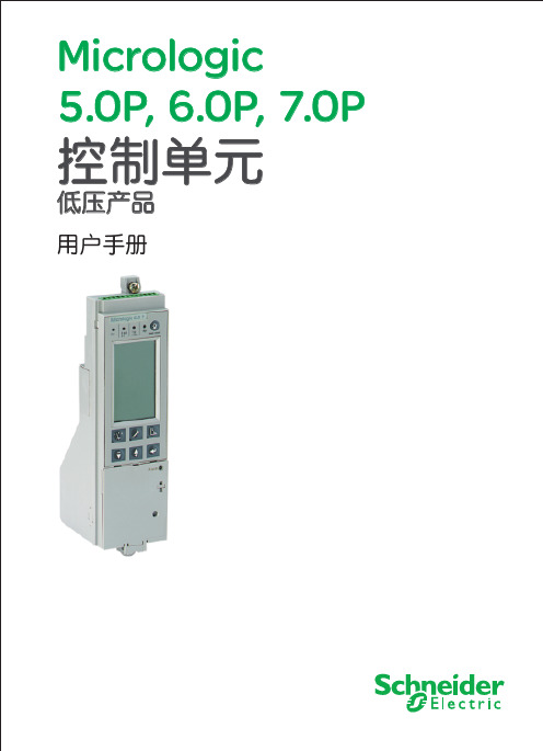
Micrologic 5.0 P 控制单元
Micrologic 6.0 P 控制单元
(*)这些按钮包括一个LED,指示激活的菜单
Micrologic 7.0 P 控制单元
4 Micrologic P
Schneider Electric
熟悉 Micrologic P
设定过程
拨盘
n 拨盘用来设置Micrologic P型控制单元过 载、短路保护,接地故障和漏电保护的保护 阈值和脱扣延时。 n 如果达到设定值,保护功能将按预设延时 使断路器脱扣。 n 出厂拨盘整定值为最小值。
n 保存设定
确认新的设置 吗?
当在 , 或
存修改值
三个菜单中作了设定,可保
¨ 选择是保存修改 ¨ 选择否取消修改且保持初始值 ¨ 屏幕保持显示直到选择了是或否
否 是
E71657A
12 Micrologic P
Schneider Electric
E60391A
E60105A
菜单选择
计量
按
按钮选择“计量”菜单
I1, I2, I3, IN 流 (根据系统类型)。
最大电流
储存和复位最大电流计量
电压测量
U (V)
瞬时电流 平均 3 不平衡 3 相序
选择下列部分:
瞬时相—相 U12, U23, U31 和相—中性线 V1N, V2N, V3N 电压 (根据系统类型) 相—相电压的平均电压 U
10 Micrologic P
Schneider Electric
菜单选择
选择主菜单
Micrologic P 控制单元提供了主屏选择和三个菜单: n 主屏显示持续测量的相电流 (I1, I2, I3) 和中性线电流 (In)(如果有中性线电流) n “计量”菜单 n “历史记录,维护和设定”菜单 n “保护”菜单
MiCOM P12x 典型应用说明
负序过流
Function 负序过流 I2>> II 段
No
Yes 投入 No 退出 Yes 投入 No 退出
[49]
THERM OL
THERM OL
热过负荷
No
热过负荷
Yes 投入 No 退出
[37]
UNDER CURRENT
Function I<
低电流
No
低电流
Yes 投入 No 退出
[79] Auto Reclose 重合闸
2. 应用实例
2.1 概述 利用 MiCOM P123,对放射状电网系统的进线提供三段过流保护,一次
系统如下图所示。进线做为电源,馈线为负荷。
进线
闭锁瞬时过流
母线 馈线 1
馈线 2
跳闸 跳闸反馈
馈线 n
馈电线保护的瞬时过流信号集中在一起接到进线保护“闭锁逻辑”的逻 辑输入端。利用闭锁逻辑功能(BLOCK LOGIC),编程设定为禁止过流 1 段 I>。将过流 3 段 I>>>门坎动作时间设置为极短(<60 ms),门槛起动值很大 (> 10In)。
Function Ie>
零序
1
段
No
[50N/51N] E/Gnd
零序保护
Function Ie>>
零序
2
段
No
Yes 投入 No 退出 Yes 投入 No 退出
Function Ie I>>>
零序 3 段
No
Yes 投入 No 退出
[46] NEG
Function I2>
负序过流 段
Microchip电子产品说明书

TREE 3: POWER MANAGEMENT 2Supervisors & Voltage Detectors Unique Strengths (So What)Broad Portfolio(It's likely we have your part)Small Packages: SOT-23 and SC-70 (Saves space)Industrial Standard Crosses (Replace high priced and poor delivery suppliers)Battery Management Unique Strengths (So What)Wide variety of charging solutions for Li-Ion batteries(We have the solution for you)Small SOT-23, MSOP, DFN and QFN packages (Saves space)DC-DC Converter (So What)Low-voltage operation (Saves Power)PFM/PWM Auto switch mode (PFM at low loads reduces current, saves power)Small SOT-23 packaging (Saves space)Step-down, Step-up (Efficiently increase or decrease voltage) Charge Pumps (So What)Low-voltage operation (Battery operation)Small SOT-23 packaging (Saves space)Step-down, Step-up (Efficiently increase or decrease voltage)Doubling & Inverting (Meets V OUT needs) Low-Frequency capable (Reduces EMI)Low-Current Operation (Saves power)LDO Unique Strengths (So What)Hundreds of voltages, currents, packages (We have a match for the need)0.5% V OUT accuracy (Fills precision need)Up to 1.5A output current(Able to power high load applications)Op Amp Unique Strengths (So What)Low current versus GBWP (Saves power)TC and MCP6XXX devices RR-I/O (Expands usable voltage range)MCP604X 1.4V operation(Two alkaline cells 90% used =1.8V)MCP644X, 450 nA operation (Use the batteries even longer)Comparators Unique Strengths (So What)Low current versus propagation delay (Saves power)Integrated Features (Saves space)1.8V and 1.4V operation (That stuff about the batteries)Programmable Gain Amplifier Unique Strengths (So What)MUX inputWide bandwidth (2 to 12 MHz) (Reduces demand on MCU I/O)System control of gain(Changes easier through software configurable hardware)TREE 5: LINEARTemperature Sensor Unique Strengths (So What)Wide variety of solutions: logic, voltage and digital output products(Multiple sensor needs met)Small packages (Saves space)Low operating current(Saves power, smaller supply)Field or factory programmable (Low cost vs. flexibility)Programmable hysteresis (Stop system cycling)Multi-drop capability (Great for large systems)Beta compensation (Compatible with processor substrate diodes)Resistance error correction (Compensates for measurement error from long PCB traces)Fan Controllers Unique Strengths (So What)Closed loop fan control (Adjust to meet target speed even on aging fans)Integrated temperature sensing (Consolidate thermal management)Multiple temperature measurements drive one fan (Consolidate thermal management)Built-in ramp rate control and spin up alogorithm (Quick time to market, lower acoustic noise)Ability to detect/predict failure of less expensive 2-wire fans (Saves system cost)Unique solutions for extending fan life and reducing acoustic noise(Less power, nuisance and long fan life)TREE 6: MIXED-SIGNALADC Unique Strengths (So What)Low current at max sampling rate (Saves power, system cost)Small SOT-23 and MSOP packages (Saves space)Up to 24-bit resolution(Ideal for precision sensitive designs)Differential & single ended inputs (Able to cover various design needs)Up to 6 ADC per device(Save board space, system cost)DAC Unique Strengths (So What)Low Supply Current (Saves power)Low DNL & INL (Better accuracy)Extended Temperature Range(Suitable for wide temperature applications)Digital Potentiometers Unique Strengths (So What)64/256 tap (6-bit to 8-bit resolution)(Sufficient resolution for most applications)Non-volatile Memory(Remembers last wiper setting on power up)WiperLock™ Technology(Locks NV memory setting-better than OTP)Small SOT-23 and 2 × 3 DFN packages (Saves space)Low CostMOSFET Drivers (So What)4.5V up to 30V Supply voltages (Fills many application needs)Up to 12A Peak output current(Able to meet demanding design needs)Outstanding robustness and latch-upi mmunity (Ours work when the others burn up)Low-FOM MOSFETs(Support high-efficency applications)TREE 4: POWER MANAGEMENT 3LIN Unique Strengths(So What)Compliant with LIN Bus Specs 1.3, 2.0, 2.1 andSAE J2602 (Allows for reliable interoperability)High EMI Low EME (Meets OEM requirements)On-board V REG available(Saves space, allows for MCU V CC flexibility)CAN Unique Strengths(So What)Simple SPI CAN controller is an easy way toadd CAN Ports (Short design cycles)High speed transceiver meets ISO-11898 (Drop inreplacement for industry standard transceivers)Low-cost, easy-to-use development tools(Tools easy to buy/use, quick design)I/O Expanders Unique Strengths(So What)Configurable inputs (interrupt configuration flexibility)Interrupt on pin change, or change fromregister default (interrupt source flexibility)Can disable automatic address incrementingwhen accessing the device(allows continual access to the port)The 16-bit devices can operate in 8-bit or 16-bitmode (easy to interface to 8-bit or 16-bit MCUs)IrDA Unique Strengths (So What)IrDA protocol handler embedded on chip(Complex design issue solved)Low cost developer's kit available to assistInfrared design-in (Quick design cycle)Small, cost-effective way of replacing serial links(No more wires)Enables system to wirelessly communicatewith PDA (Wireless connectivity solution) TREE 8: INTERFACEAnalog & InterfaceQuestion TreesAnalog & Interface Development ToolsDemonstration Boards, Evaluation Kits and AccessoriesAnalog & Interface LiteratureADM00313EV: MCP73830L 2 × 2 TDFN Evaluation BoardADM00352: MCP16301 High Voltage Buck Converter 600 mA Demonstration BoardADM00360: MCP16301 High Voltage Buck Coverter 300 mA D2PAK Demonstration BoardADM00427: MCP16323 Evaluation Board (Supports MCP16321 and MCP16322)ARD00386: MCP1640 12V/50 mA Two Cells Input Boost Converter Reference DesignMCP1252DM-BKLT: MCP1252 Charge Pump Backlight Demonstration BoardMCP1256/7/8/9EV: MCP1256/7/8/9 Charge Pump Evaluation BoardMCP1630RD-LIC1: MCP1630 Li-Ion Multi-Bay Battery Charger Reference DesignMCP1630DM-NMC1: MCP1630 NiMH Battery Charger Demonstration BoardMCP1640EV-SBC: MCP1640 Sync Boost Converter Evaluation BoardMCP1640RD-4ABC: MCP1640 Single Quad-A Battery Boost Converter Reference DesignMCP1650DM-LED1: MCP165X 3W White LED Demonstration BoardMCP1726EV: MCP1726 LDO Evaluation BoardMCP73831EV: MCP73831 Evaluation KitMCP7383XEV: MCP73837/8 AC/USB Dual Input Battery Charger Evaluation BoardMCP7383XRD-PPM: MCP7383X Li-Ion System Power Path Management Reference DesignMCP7384XEV: MCP7384X Li-Ion Battery Chager Evaluation BoardMCP73871EV: MCP73871 Load Sharing Li-Ion Battery Charger Evaluation BoardTC1016/17EV: TC1016/17 LDO Evaluation BoardVSUPEV: SOT-23-3 Voltage Supervisor Evaluation BoardPowerManagementThermalManagementMCP9700DM-PCTL: MCP9700 Thermal Sensor PICtail Demonstration BoardMCP9800DM-PCTL: MCP9800 Thermal Sensor PICtail Demonstration BoardTC72DM-PICTL: TC72 Digital Temperature Sensor PICtail Demonstration BoardTC74DEMO: TC74 Serial Daughter Thermal Sensor Demonstration BoardTC1047ADM-PCTL: TC1047A Temperature-to-Voltage Converter PICtail™ Demonstration BoardSerial GPIODM-KPLCD: GPIO Expander Keypad and LCD Demonstration BoardMCP23X17: MCP23X17 16-bit GPIO Expander Evaluation BoardInterface MCP2515DM-BM: MCP2515 CAN Bus Monitor Demonstration BoardMCP2515DM-PTPLS: MCP2515 PICtail™ Plus Daughter BoardMCP2515DM-PCTL: MCP2515 CAN Controller PICtail Demonstration BoardMCP215XDM: MCP215X/40 Data Logger Demonstration BoardMCP2140DM-TMPSNS: MCP2140 IrDA® Wireless Temp Demonstration BoardLinear ADM00375: MCP6H04 Evaluation BoardARD00354: MCP6N11 Wheatstone Bridge Reference DesignMCP651EV-VOS: MCP651 Input Offset Evaluation BoardMCP661DM-LD: MCP661 Line Driver Demo BoardMCP6S22DM-PCTL: MCP6S22 PGA PICtail Demonstration BoardMCP6S2XEV: MCP6S2X PGA Evaluation BoardMCP6SX2DM-PCTLPD: MCP6SX2 PGA Photodiode PICtail Demonstration BoardMCP6SX2DM-PCTLTH: MCP6SX2-PGA Thermistor PICtail Demonstration BoardMCP6V01RD-TCPL: MCP6V01 Thermocouple Auto-Zero Ref DesignMCP6XXXDM-FLTR: Active Filter Demo BoardPIC16F690DM-PCTLHS: Humidity Sensor PICtail Demonstration BoardMixed-Signal MCP3221 DM-PCTL: MCP3221 12-bit A/D PICtail Demonstration BoardMCP3421DM-BFG: MCP3421 Battery Fuel Gauge Demonstration BoardMCP3551DM-PCTL: MCP3551 PICtail Demonstration BoardMCP355XDM-TAS: MCP355X Tiny Application Sensor Demonstration BoardMCP355XDV-MS1: MCP3551 Sensor Demonstration BoardMCP402XEV: MCP402X Digital Potentiometer Evaluation BoardMCP4725EV: MCP4725, 12-bit Non-Volatile DAC Evaluation Board (Preferred One)MCP4725DM-PTPLS: MCP4725, 12-bit Non-Volatile DAC PICtail Demonstration BoardADM00398: MCP3911 ADC Evaluation Board for 16-bit MicrocontrollersCorporate Microchip Product Line Card - DS00890Brochures Analog and Interface Product Selector Guide - DS21060Low Cost Development Tools Solutions Guide - DS51560Analog and Interface Guide (Volume 1) - DS00924Analog and Interface Guide (Volume 2) - DS21975Cards Analog Highlights Card - DS21972Microchip Op Amp Discovery Card - DS21947Analog & Interface Question Trees - DS21728Mirochip SAR and Delta-Sigma ACD Discovery Card - DS22101Software Tools MAPS - Microchip Advanced Product SelectorAnalog & Interface Treelink Products PresentationDesign Guides Analog-to-Digital Converter Design Guide - DS21841Digital Potentiometers Design Guide - DS22017Programmable Gain Amplifiers (PGAs), Operational Amplifiersand Comparators Design Guide - DS21861Interface Products Design Guide - DS21883Signal Chain Design Guide - DS21825Power Solutions Design Guide - DS21913Temperature Sensor Design Guide - DS21895Voltage Supervisors Design Guide - DS51548DS21728JPowerManagementLDO & SwitchingRegulatorsCharge PumpDC/DC ConvertersPower MOSFETDriversPWM ControllersSystem SupervisorsVoltage DetectorsVoltage ReferencesLi-Ion/Li-PolymerBattery ChargersUSB Port PowerControllersMixed-SignalA/D ConverterFamiliesDigitalPotentiometersD/A ConvertersV/F and F/VConvertersEnergyMeasurement ICsCurrent/DC PowerMeasurement ICsInterfaceCAN PeripheralsInfraredPeripheralsLIN TransceiversSerial PeripheralsEthernet ControllersUSB PeripheralLinearOp AmpsInstrumentationAmpsProgrammableGain AmplifiersComparatorsSafety & SecurityPhotoelectricSmoke DetectorsIonization SmokeDetectorsIonization SmokeDetector Front EndsPiezoelectricHorn DriversThermalManagementTemperatureSensorsFan Control& HarwareManagementMotor DriveStepper and DC3Ф BrushlessDC Motor DriverTREE 7: MOTOR DRIVE Stepper Unique Strenghts(So What)Industrial standard footprint(Footprint compatible to industrial leaders)Perfect PIC® MCU companion chip(Solid field support)Micro-stepping ready(Enhanced performance)Integration protections(Simplify software development)3-Phase BLDC Unique Strengths(So What)Full-wave sinusoidal(Quiet operation, low mechanical vibration)Sensorless operation (Minimum externalcomponents, no software required)Thin form factor(Fits space concerned applications)Information subject to change. The Microchip name and logo, the Microchip logo, dsPIC, PIC are registered trademarks and MiWi, PICtail and ZENA are trademarks ofMicrochip Technology Incorporated in the U.S.A. and other countries. All other trademarks mentioned herein are property of their respective companies.© 2012, Microchip Technology Incorporated. All Rights Reserved.。
科瑞斯通 P12xy_说明书
MiCOMP12x/y 保护装置适用于各种要求过流和接地故障保护的场合。
P12x系列(不带方向)保护装置包括:从单相/接地继电保护装置P120直至多功能的三相和接地保护装置P123。
P12y系列方向继电保护装置包括:从单相/接地继电保护装置P125直至多功能的三相和接地保护装置P127,并带完整的电压保护功能。
MiCOM P12x 和 P12y 继电保护装置能轻松胜任各种应用场合,并适用于各种工况条件。
保护装置前面板操作界面简明,功能强大。
整定软件 MiCOM S1 Studio 使用户能方便地完成配置和读取所有测量值、以及装置中储存的各种以维护和故障后分析为目的的信息。
可选的通讯规约使保护装置能与变电站控制系统或SCADA系统接口。
该系列的MiCOM保护装置的机箱高度尺寸相同,皆为4U金属壳体,其宽度为20TE(P120/1/2/3和P125)或30TE(P126和P127),适用于屏柜安装或机架安装。
优点• 集成多种功能,提供高性价比解决方案• 提供多种语言菜单,• 灵活的过流保护,可结合逻辑编程功能• 多重自动重合闸功能,减少系统故障扰动时间•调试软件• 完善的测量、监视、故障记录功能光耦输入输入类型光隔离输入功率10mA每个输入输入识别时间<5ms逻辑输入电气特性订货代号辅助电源电压范围逻辑输入的工作电压范围*最小触发电压A24~60Vdc24~250Vdc; 24~240Vac15VdcF48~250Vdc; 48~240Vac (EA**)24~250Vdc; 24~240Vac15VdcT48~250Vdc; 48~240Vac 24~250Vdc; 24~240Vac15VdcH48~250Vdc; 48~240Vac 105~145Vdc105Vdc V48~250Vdc; 48~240Vac 100Vdc; -30%/+20%77VdcW48~250Vdc; 48~240Vac 220Vdc; -30%/+20%154Vdc(*) 光耦输入的工作电压允许偏差为DC±20%,AC-20%至10%(**) 光耦输入的辨认时间经EA认证,采用24点采样滤波(50Hz时为15ms)开出接点开出接点类型银镍干接点!。
MiCOM P12y定值清单及说明(1.C)
第 2 页/共 22 页 定值清单及说明
缺省值 P125 OP.PARAMETERS 运行参数 Password 密码 AAAA AAAA AAAA R/W 读/写 Language 语言 English English English R/W 读/写 Description 描述 Reference 参考 P125-ALST P126-ALST P127-ALST R读 R/W 读/写 Software Version 软件版 X.X 本 Frequency 频率 Input Status 态 Relay Status 态 Date 日期 50Hz 开入量状 XXXX 开出量状 XXXXXX N.A X.X 50Hz XXXXXXX XXXXXXXX XX/XX/XX X.X 50Hz XXXXXXX XXXXXXXX XX/XX/XX R 读 P126 P127 模式
CONFIGURATION
配置
General Options 通用选项 VT Connection VT 接法 N.A. N.A. 3Vpn R/W 3Vpn or 2Vpp+Vr or 2Vpn+Vr 读/写 R/W 读/写 IA IA IN
Default Display 默认显示 IN Default Display 默认显示
Parity
校验
None
None
None
读/写 无校验-偶校验-奇校验 Data Bits 数据位 8 8 8 R/W 读/写 Stop Bit 停止位 1 1 1 R/W 读/写 Relay Address 继电器地 址 [67] Directional/non directional Phase OC [67]方向/无方向相过流 1 1 1 R/W 读/写 N.A N.A 1 255 1 1 or 2 7 or 8
MiCOM P12x定值清单及说明

菜单文本
缺省整定
CONFIGURATION 配置
E/Gnd CT primary 接地 CT 一次测
E/Gnd CT sec 接地 CT 二次测
1000 1
LED5/6/7/8
关联指示灯
I>
5/6/7/8
Group Select
定制组选择
1
菜单文本
缺省设置
PROTECTION G1/G2 [50/51]Phase OC
步长
1
9999
1
1或5
I>、tI>、 I>>、tI>>、I>>>、 tI>>>、Ie>、tIe>、 Ie>>、tIe>>
Ie>>>、tIe>>>、 Therm Trip、 Brkn.Cond、CB Fail、tI2>、
tI2>>、Input1、Input2、Input3、 Input4、Input5、Recloser Run、 Recloser Blocked、tAux1、tAux2
0.005 x Ien 0.005 x Ien
DMT 定时限或 IDMT 反时限
Short time inverse(ALSTOM)、Standard Inverse(IEC)、Very inverse(IEC)、 Extremely inverse(IEC)、Lone time inverse(ALSTOM)、Short time inverse (CO2)、Moderately inverse (ANSI)、Inverse(CO8)、Very
YES
闭锁 tIe>>>
MiCOM P24x技术说明书(1)
MiCOM P521 技术说明书_v1.C_

2.1.2.3
门槛值
...............................................................................................25
2.1.2.4
Laborelec
曲线
............................................................................................27
2.1.3
热过负荷保护 断线检测 联跳功能
2.1.6.1
.........................................................................................................29
2.1.4
断路器失灵保护
.....................................................................................................30
2.1.10
............................................................................................................36
2.1.11
合于故障的保护 辅助计时器 整定组选择 闭锁功能
(SOTF) .........................................................................................36
MICOMP整定说明(精品)
MICOM P241 整定说明一、面板介绍 (2)二、报警信息的复归及故障记录查看 (3)2.1、故障及报警信息查看及复归 (3)2.2、历史记录查询 (3)2.3、自定义LED指示灯的复归 (4)三、测量值的查看 (5)3.1、模拟量查看 (5)3.2、开关量查看 (6)四、保护设置 (6)4.1、配置菜单的设置 (6)4.2、CT和PT变比的设置 (9)4.3、保护功能参数的设置 (11)4.3.1 短路保护功能(相过流保护) (11)4.3.2 灵敏零序保护功能 (13)4.3.3 基于计算零序电流的保护 (14)4.3.4 电压的保护设置 (15)一、面板介绍L C D用户可编程L E D键盘测试端口前端通讯端口 电池下盖功能固定的L E D序列号和I, V 的额定值上盖1、 液晶显示(LCD ):可显示各项数据。
如整定值、测量值、报警信息等。
3、 用户自定义指示灯:(LED1、LED2‥‥‥LED7、LED8)可自定义功能。
可设为过流、速断、零序、低电压等。
如LED1定义为“过流”,当过流保护动作时,LED1点亮,为红色。
4、操作键盘:用户可通过、、、 四个键来进入各级彩单、移动光标、修改定值等。
键用来确认选项和个修改整定值。
5、阅读键:用来查看报警及故障信息。
6、复位键:用来复位故障及报警信息。
7、电池:当继电器失电时,用来保存事件纪录、故障记录、及时钟等。
8、前端通讯口:为RS232通讯接口,与当地PC 机通讯,可通过调试软件对保护装置进行定值整定、查看实时测量值、查看事件记录、故障记录、故障录波等。
9、型号、序列号:标有保护装置的具体型号、出厂序列号、工作电压范围等信息。
二、报警信息的复归及故障记录查看2.1、故障及报警信息查看及复归和键用于复位和读取故障及报警信息。
(键来查看报警信 息的内容,可重复按键来连续显示不同的报警内容。
告警指示灯不再闪烁时,可按键清除报警信息,按一下复位键清除一条告警信息,如有多条告警信息,则需多按几下。
MiCOMP12y技术说明书(1C)

3.1.1 三相过电流保护(P126、P127) ........................................19 3.1.2 方向接地保护(P125, P126 & P127).....................................20 3.1.3 热过负荷保护(P126、P127) ..........................................22 3.1.4 低电流保护(P126、P127) ............................................23 3.1.5 负序过电流保护(P126 & P127) .........................................23 3.1.6 断线检测(P126 & P127) ...............................................24 3.1.7 零序过电压保护(P125, P126 & P127)...................................24 3.1.8 低电压保护(P127) ...................................................24 3.1.9 过电压保护(P127) ...................................................25 3.1.10 自动重合闸 (P126 & P127) ............................................25 3.2 自动控制功能 ..............................................................27 3.2.1 负荷冷启动(P126 和 P127) .............................................27
MiCOM P12x使用说明书
障,如典型的通信故障等。下侧 4 个为用户自定义指示灯。
4. 上、下盖板区域:顶部和底部盖板都可翻开。翻开上盖板可查看装置
型号、系列号以及额定值等;翻开下盖板可看到装置备用电池以及 9
针 RS232 串口 D 形母头。
3. 液晶显示
3.1 正常显示画面
正常情况下,MiCOM P12x 系列保护装置可连续显示所选的电流测量 值,可以是某个相电流或零序电流。
第一段负序过流门槛启动
第一段负序过流门槛延时信号启动
第二段负序过流门槛启动
第二段负序过流门槛延时信号启动
断路器故障指示,该信号从指定的逻辑输入处得到 (在 AUTOMAT.CTRL/Inputs(自动控制/输入)菜单 中设置)。 断路器动作(或跳闸)时间超过了 AUTOMAT.CTRL/CB Supervision(自动控制/断路器 监视)菜单中设置的时间。 断路器动作次数超出了 AUTOMAT.CTRL/CB Supervision(自动控制/断路器监视)菜单中设置的 值。 开断电流的测量值大于 AUTOMAT.CTRL/CB Supervision(自动控制/断路器监视)菜单中设置的 值。 断路器跳闸电路故障时间超出在 AUTOMAT.CTRL/CB Supervision(自动控制/断路器 监视)菜单中的设置的监视时间 t SUP。
目录
1.
装置介绍
2.
装置面板布置
3.
液晶显示
3.1 正常显示画面
3.2 故障报告显示
4.
菜单
4.1
主菜单结构
4.2 菜单操作
5.
密码
5.1 密码保护
5.2 密码的输入
5.3 密码的修改
6.
事件信息一览表
SYNCO P1系列麦克风用户手册说明书
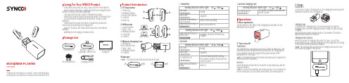
User ManualThank you for choosing SYNCO product. Please read this manual carefully before use and follow all instructions mentioned herein.Storage x1Charging cable x1Mic Windshield x11. TX Transmitter2. RX Receiver① Power Key② Working Indicator③ Built-in Microphone④ Contacts⑤ Back Clip① Volume Button② Type-C Port③ Working Indicator④ Connector⑤ Contacts① Pairing Key /Power Indicator Key② Type-C port③ Working Indicator④ ContactsCaring For Your SYNCO ProductPackage List· Please keep the product in a dry, clean, dust-free environment.· Keep corrosive chemicals, liquids and heat source away from theproduct to prevent mechanics damage.· Use only a soft and dry cloth for cleaning the product.· Malfunction may be caused by dropping, impact of external force.· Do not attempt to disassemble the product. Doing so voidswarranty.· Please have the product checked or repaired by authorizedtechnicians if any malfunctions happened.· Failure to follow all the instructions may result in mechanicsdamage.· Warranty does not apply to human errors.Lightning Connector) x14.Indicator1. Basic operations2. Turn it on/offOperationsTap the drawer to the right of the charging box and take out theTransmitter:The transmitter(s) automatically turn(s) on after be taken out, andautomatically shut down when be put back into the charging box;(Force switch on and off: long press the power button of thetransmitter for 3 seconds)*Note: The transmitter will shut down automatically if it unpaired ordisconnected for 5 minutes.3. ChargeReceiver:Insert the mobile phone device to switch on automatically, and theindicator flashes.*Note: You can check whether the mobile phone OTG is on when hereceiver indicator is not on after be inserted to the mobile phone.Transmitter:Charging case:charging.*Note:Warranty Period Warranty Exclusions and Limitations Warranty Claim ProcedureThank you for purchasing SYNCO products.1. Customers are entitled to free replacement or repair service in case of quality defect(s) found in the product under normal use within 30 days upon receipt of the product.2. Original SYNCO products are entitled to 12-month limited warranty service. The warranty period begins on the date of purchase of brand new, unused products by the first end-user.Faults resulted from inappropriate use of a product without following its operation specification1. Artificial damage, e.g. crash, squeeze, scratch, or soaking2. Modifications to a product by its user or a third party without prior written consent of SYNCO, e.g. replacement of element or circuit, label alteration3. The code on product is inconsistent with that of warranty certificate, or the code on the product or warranty certificate is altered or torn off4. All consumable accessory attached to a product, like cable, wind muff, battery5. Faults as a result of force majeure, such as fire, flood, lightning, etc.1. If failure or any problem occurs to your product after purchase, please contact a local agent for assistance, or you can always contact SYNCO’s customer service through email at **********************.2. Please retain your sales receipt and warranty certificate as proof of purchase. If any of these documents is missing, only sales return or chargeable service will be provided.3. If the SYNCO product is out of the warranty coverage, the service and the parts cost will be charged.Warranty Within the warranty period, if product defect or failure is attributableto material defection or technological problem, the defective productor defective part will be repaired or replaced without charge (serviceand materials fee).*Please register your warranty. Meanwhile, you are welcomed to contact us via Email:**********************Product Model:Date of Purchase:Serial Number:Malfunction Description :Buyer Name:Buyer Telephone :Buyer Mail :Buyer Address :Dealer :Dealer Telephone :Delivery Date :Cause of Malfunction :Maintenance Personnel :Malfunction Processing :WARRANTY CERTIFICATEWireless TransmissionRF Frequency BandWorking DistanceSampling RateBit DepthConnectorPower InputDimensionsMaterialWeightBattery TypeBattery Charging TimeCharging PortPower RequirementsDimensionsWeightDigital 2.4GHz2400-2483.5MHz492ft/150m(LOS area);164ft/50m(NLOS area)48KHz16BitType-C or Lightning OutputType-C49x30x9 (mm)ABS5gBuilt-in Lithium Battery, 300mAh1.5HType-C Port5V 2A70x43x37 (mm)58g5. Adjust the volumeTX TransmitterRX ReceiverWireless Charging Case6. Noise reductionClick the receiver volume button to adjust the volume and thenumber of indicators shows the current volume level.Double click the volume button to enable or disable mute and singleindicator keeps on when mute is on.Click the power button of the transmitter to turn on the noisereduction, and single indicator keeps on.* Double click the power button of the transmitter to turn off/on thelight effect.Specifications4. ParingPairing in the charging box:① Place the transmitter and receiver in the charging box, andconnect the contact with the contact of the charging box;② Open the charging box, press and hold the matching button onthe box for 3 seconds;Pairing in use:switched on;the frequency alignment state.**********************。
- 1、下载文档前请自行甄别文档内容的完整性,平台不提供额外的编辑、内容补充、找答案等附加服务。
- 2、"仅部分预览"的文档,不可在线预览部分如存在完整性等问题,可反馈申请退款(可完整预览的文档不适用该条件!)。
- 3、如文档侵犯您的权益,请联系客服反馈,我们会尽快为您处理(人工客服工作时间:9:00-18:30)。
3.3.1 3.3.2 3.3.3
4. 5.
模拟量输入 ............................................................... 31 开入、开出特性............................................................ 装置 技术说明书
版本 1.C
上海施耐德电气电力自动化有限公司 中国上海闵行区浦江镇漕河泾高科技园 F 区 新骏环路 188 号 6 号楼 邮编 201114 电话:+86 (0) 21 3357 6888 传真:+86 (0) 21 3357 6999
上海施耐德电气电力自动化有限公司 MiCOM P12y 系列
5.1 5.2 逻辑输入量 ................................................................33 接点开出量 ................................................................33
记录和录波(P126 和 P127) ................................................30 事件记录 .............................................................30 故障记录 .............................................................30 故障录波 .............................................................30
7.
安装尺寸 ................................................................. 35
7.1 7.2 P125 的外壳尺寸 ...........................................................35 P126 和 P127 的外壳尺寸....................................................36
8.
接线图 ................................................................... 36
8.1 8.2 8.3 P125 接线图 ...............................................................36 P126 接线图 ...............................................................37 P127 接线图 ...............................................................38
1.2
健康与安全
产品说明文档的这个安全部分的目的是为了确保正确安装和使用本产品,从而使它们能维持 在某个安全状态下。 任何关系到该设备的人员必须熟悉这部分安全说明的内容。 当电子设备处于运行状态时,该设备的某些部位会产生危险的高压。如果没有观察到告警提 示、或使用不当都可能危及人身及设备,导致人身伤害或设备受损。 在对设备接线端子部分进行接线等工作之前,本设备必须绝缘隔离。 设备的正确、安全的运行取决于适当的运输、处理,正确的存储、安装及调试,同时取决于 细心的操作、维护和使用。因此只有具备资质的人员才可以对本设备进行相应的操作。 具备资质的人员应当:
9.
装置选型 ................................................................. 39
上海施耐德电气电力自动化有限公司 MiCOM P12y 系列
第 4 页/共 40 页 技术说明书
1. 安全须知
1.1
概述
该指南以及相关的使用、操作说明文件为产品提供了与安全、调试以及产品测试相关的详细 信息,并对产品的各种标识做了描述。 安全须知中的技术数据仅是典型数据,具体设备的技术数据请查阅相关设备文档的技术数据 章节。 在着手对本设备进行任何操作之前必须仔细阅读这篇安全部分说 明,熟悉设备铭牌上的额定值。 在安装、调试或操作本产品时,请在相应的原理接线图上做好参考标识。 部分产品提供用户可自定义的可粘贴标签纸。
3.1.1 3.1.2 3.1.3 3.1.4 3.1.5 3.1.6 3.1.7 3.1.8 3.1.9 3.1.10 3.2
自动控制功能 ..............................................................27 负荷冷启动(P126 和 P127) .............................................27
3.2.1
上海施耐德电气电力自动化有限公司 MiCOM P12y 系列 3.2.2 3.2.3 3.2.4 3.2.5 3.2.6 3.2.7 3.2.8 3.2.9 3.2.10 3.2.11 3.3
第 3 页/共 40 页 技术说明书
辅助计时器(P125, P126 和 P127) ......................................27 定值整定组的选择 .....................................................27 基于选择性的逻辑方案(P126 和 P127)...................................28 断路器位置监视 .......................................................28 断路器状态监视(P126 和 P127) ........................................29 断路器失灵(P126 和 P127) ............................................29 跳闸回路监视(P126 和 P127) ...........................................29 SOTF 手合于故障(P126 和 P127) .....................................29 复合电压闭锁过流保护(P127) .........................................29 与(AND) 逻辑功能 (P126 和 P127) ....................................29
2.1 额定参数 ..................................................................10 电源 .................................................................10 频率 .................................................................10 电流输入 .............................................................10 电压输入 .............................................................11 逻辑输入 .............................................................11 继电器输出接点 .......................................................11
2.1.1 2.1.2 2.1.3 2.1.4 2.1.5 2.1.6 2.2 2.3 2.4 2.5 2.6 2.7
耐受高压水平 ..............................................................12 电气环境 ..................................................................12 环境 ......................................................................13 保护精度 ..................................................................15 自动功能时间精度 ..........................................................16 测量精度 ..................................................................17
第 2 页/共 40 页 技术说明书
目 录
1. 2. 装置简介 .................................................................. 4 技术参数 ................................................................. 10
6.
通讯 ..................................................................... 34
6.1 6.2 RS485 背部通讯口 .........................................................34 RS232 前部通讯口 .........................................................34