思科实验实验报告4
思科实验报告

2.HUB(集线器)或交换机1台;
3.制作完成的直通双绞线若干;
4•机房的电脑能上网。
三、实验内容
1.每个学生申请一个邮箱,交给老师;
2.老师在AC网站上导入学生信息,系统会将每个学生的ID号和
Password自动发至学生注册的邮箱;
3•然后学员在浏览器中输入以下地址登录全球思科网站:
Win2000或Win XP系统);
2.HUB(集线器)或交换机1台;
3.十字螺丝刀、压线钳各2把,测线仪2个;
4.水晶头和超五类双绞线若干;
三、实验内容
1.使用所提供的网线制作工具(压线钳和测线仪)和器材参照T568B
标准制作直通双绞线;
2.使用所提供的网线制作工具(压线钳和测线仪)和器材参照T568B
网络应用基础课程实验报告
院 系:
专 业:
班 级:
指导老师:
学 号:
姓 名:
实验一Google地球和维基3
实验二AC网站注册6
实验三网线制作1.0
实验四Ad-Hoc点对点无线局域网方案13
实验五基本结构型无线局域网方案17
实验六交换机的基本配置2 1
实验学时
2
实验时间
实验地点
同组成员
指导老师:
实验一
一、实验目的
2•什么OSI模型?OSI模型各层从最高层到最低层的正确顺序是什么 样的?
OSI开放式系统互联。一般都叫OSI参考模型
是ISO(国际标准化组织)组织在1985年研究的网络互联模型。
最早的时候网络刚刚出现的时候,很多大型的公司都拥有了网络技术公
司内部计算机可以相互连接。可以却不能与其它公司连接。因为没有一个 统一的规范。计算机之间相互传输的信息对方不能理解。所以不能互联。
思科聚合组实验报告
一、实验目的1. 理解并掌握思科链路聚合(EtherChannel)的基本概念和技术原理。
2. 学习配置思科交换机上的聚合组,包括物理链路的聚合、聚合模式的设置以及链路聚合的配置和验证。
3. 通过实验验证聚合组在提高网络带宽和冗余性方面的作用。
二、实验环境1. 设备:两台思科交换机(如:Catalyst 3560系列)、两台PC终端、网线若干。
2. 软件:思科IOS软件或模拟器(如:GNS3)。
三、实验原理链路聚合(EtherChannel)是一种将多个物理链路捆绑成一个逻辑链路的技术,从而实现更高的带宽和冗余性。
在思科交换机上,可以通过配置聚合组来实现链路聚合。
四、实验步骤1. 物理连接:将两台交换机的指定端口通过网线连接,形成物理链路。
2. 配置交换机:- 进入交换机配置模式。
- 配置端口模式为trunk。
- 创建聚合组,并将物理端口加入到聚合组中。
- 配置聚合模式(如:LACP、PAgP或on)。
- 配置负载均衡策略(如:源MAC地址、目标MAC地址等)。
3. 验证配置:- 使用show etherchannel summary命令查看聚合组的建立情况。
- 使用show etherchannel port命令查看聚合端口的带宽和状态。
- 在PC终端上测试网络连通性,验证聚合组是否正常工作。
五、实验结果与分析1. 聚合组建立情况:通过show etherchannel summary命令,可以看到聚合组的建立情况,包括聚合组ID、端口状态、链路状态等。
2. 聚合端口带宽:通过show etherchannel port命令,可以看到聚合端口的带宽和状态,包括端口聚合状态、带宽利用率等。
3. 网络连通性测试:在PC终端上测试网络连通性,可以发现聚合组正常工作,提高了网络带宽和冗余性。
六、实验总结通过本次实验,我们成功配置了思科交换机上的聚合组,并验证了其在提高网络带宽和冗余性方面的作用。
实验结果表明,链路聚合是一种有效的网络技术,可以满足大型网络对带宽和可靠性的需求。
思科外网设计实验报告
思科外网设计实验报告1. 实验目的本实验旨在通过思科外网设计,搭建一个可靠高效的企业网络架构,实现多地点的用户之间的通信和数据传输。
2. 实验背景在现代企业中,随着业务范围的扩展和跨地域办公的需求增加,构建一个高可用性和高可靠性的企业网络架构变得至关重要。
如何在通信链路稳定性、数据安全性和网络带宽等方面做出权衡是我们在思科外网设计实验中需要解决的问题。
3. 实验环境- 思科路由器- 思科交换机- 企业内部网络资源4. 实验步骤4.1 确定网络拓扑结构我们的设计思路是采用分布式的网络拓扑结构,通过多个网络节点实现分流和负载均衡。
在这个实验中,我们选择了三个地点进行布局,分别是总部、分公司A 和分公司B。
4.2 配置思科路由器和交换机在总部和分公司A、分公司B的每个节点上,安装思科路由器和交换机,并对其进行相应的配置,包括IP地址设置、静态路由配置、VLAN设置等。
4.3 建立VPN隧道在总部和分公司A、分公司B之间,建立虚拟私有网络(VPN)隧道,以实现安全的跨地域通信。
我们选择了IPsec VPN协议,并使用思科路由器的IPsec VPN功能进行配置。
4.4 配置网络安全功能在总部和分公司A、分公司B的每个节点上,启用网络安全功能,包括防火墙、入侵检测系统(IDS)和入侵防御系统(IPS)等,用于保护企业内部网络免受来自外部的网络攻击。
4.5 实施网络性能优化通过优化网络设备的配置和使用一些网络加速技术,如负载均衡、链路聚合等,提高网络的稳定性和传输速率,确保用户在不同地点之间的通信和数据传输的顺畅和高效。
5. 实验结果与分析经过实验,我们成功搭建了一个可靠高效的企业网络架构。
通过VPN隧道,总部和分公司A、分公司B之间可以安全地进行跨地域通信。
网络安全功能的启用有效地保护了企业内部网络的安全性,防止了来自外部的攻击和入侵。
网络性能优化措施的实施,加快了数据传输速率,提高了用户的体验。
6. 实验总结通过思科外网设计实验,我们深入了解了企业网络架构的设计原理与实施技术。
思科实训报告

思科实训路由器操作及配置班级:网络1031姓名:闫晓彤学院:轻工山西轻工职业技术学院2011年6月17日实验 1 简单的路由配置与抓包工具的使用实验目的1 学习使用CISCO仿真软件;2 学习使用路由配置基本命令.实验要求单独配置自己的路由器,完成路由的配置后,各路由器要能够ping通拓扑图中的所有网段。
并且使用抓包工具观察ping的数据流.实验项目性质设备的连通性。
实验设备计算机及CISCO仿真软件。
连接方式IP配置表名称地址网关PC0 172.168.1.12172.168.1.1PC1 172.168.1.22172.168.1.1路由器172.168.1.23172.168.1.1实验步骤1 将路由器、交换机和两台终端设备拖拽出来。
2 连接路由器和交换机,连接交换机和两台终端设备。
3 配置PC0,PC1 的IP地址,4 用抓包软件来看数据流的传输方向是否连通。
5 在PC0上使用PING命令去检测是否和PC1相连通.实验数据及结果数据流:先从PC0发送数据包到交换机,再从交换机将数据包发送到PC1,然后数据包从PC1返回到交换机,交换机将数据包发送到PC0,完成数据流的流通。
实验总结在试验的过程中我学会了用思科仿真软件来使用简单的路由配置和抓包操作。
通过使用PING命令来配置路由器等。
实验二简单的路由配置与抓包工具的使用一:实验目的1 学习使用CISCO仿真软件;2 学习使用路由配置基本命令。
二:实验要求单独配置自己的路由器,PC,完成路由与PC的配置后,各路由器要能够ping通拓扑图中的所有网段。
三:实验项目性质检测设备之间的连通性。
四:实验设备计算机及CISCO仿真软件。
五:连接方式IP配置表名称地址网关PC0 172.16.1.23 172.16.1.1PC1 172.16.1.13 172.16.1.1PC2 172.17.1.23 172.17.1.1PC3 172.17.1.13 172.17.1.1Router0 172.16.1.1 2172.16.1.1Router1 172.17.1.1 172.17.1.1六:实验步骤1 将两台路由器、两台交换机、以及四台PC机拖到思科仿真软件中。
思科实验报告

思科实验报告一:实验目的与要求1. PC -0——PC -3属于内网,使用私有地址;其余网络节点位于外网,使用公有地址;2. PC -0和PC -2属于VLAN10,PC -1和PC -3属于VLAN20;3. VLAN10只允许访问Web 服务器(PC -4),VLAN20只允许访问FTP 服务器(PC -5)。
二:实验拓扑结构图三:IP 地址规划表Router0:Router2:Router3: Router4:四:配置文件Switch2:Vlan 10 添加vlan Vlan 20 Int f0/1Switchport access vlan 10 允许vlan10通过 Int f0/2Switchport access vlan 20 允许vlan20通过 Int f0/3Switchport mode trunk 设置主干道Switch3:Vlan 10 添加vlan Vlan 20 Int f0/1Switchport access vlan 10允许vlan20通过 Int f0/2Switchport access vlan 20 允许vlan20通过Int f0/3Switchport mode trunk 设置主干道Switch0:Int f0/1Switchport mode trunk 设置三条主干道Int f0/2Switchport mode trunkInt f0/3Switchport mode trunkSwitch1:Vlan 10 添加vlanVlan 20Int f0/1Switchport access vlan 10 允许vlan10通过Int f0/2Switchport access vlan 20 允许vlan20通过Int f0/3Switchport mode trunk 设置主干道Router3:int f0/0 设置子接口no ip addno shutint f0/0.1ip add 192.168.1.254encap dot1q 10no shutint f0/0.2ip add 192.168.2.254encap dot1q 20no shutip route 0.0.0.0 0.0.0.0 11.1.1.2 添加默认路由int f0/0.1 设置NAT地址池ip nat insideint s0/0/0ip nat outsideaccess-list 10 permit 192.168.0.0 0.0.255.255 允许网段转换ip nat pool out(名字)202.106.0.1 202.106.0.100 net 255.255.255.0 ip nat inside source list 10 pool outRouter0:ip route 11.0.0.0 255.0.0.0 11.1.1.1 添加静态路由router rip 使能rip协议version 2 使用rip2协议ip route 13.0.0.0 添加rip路由ip route 14.0.0.0Router2:router rip 使能rip协议version 2 使用rip2协议ip route 13.0.0.0 添加rip路由ip route 14.0.0.0Router1:router rip 使能rip协议version 2 使用rip2协议ip route 12.0.0.0 添加rip路由ip route 14.0.0.0ip route 15.0.0.0 255.0.0.0 15.1.1.2 添加静态路由Router4:ip route 0.0.0.0 0.0.0.0 11.1.1.2 添加默认路由access-list 101 permit ip 192.168.1.0 0.0.0.255 host 202.1.1.1 设置访问控制列表access-list 101 deny ip any anyaccess-list 102 permit ip 192.168.2.0 0.0.0.255 host 202.1.1.2access-list 102 deny ip any anyint s0/0/0ip access-group 101 inip access-group 102 in。
思科实验报告

思科实验报告思科实验报告一、实验目的本实验旨在通过模拟真实的网络环境,了解思科设备的配置和管理方法,掌握基本的网络协议和概念,加深对网络技术的理解。
二、实验原理思科设备是全球领先的网络设备供应商,其产品在企业和组织中得到广泛应用。
本实验将使用思科模拟器软件,模拟真实的网络环境,包括路由器、交换机、终端设备等。
通过网络协议的配置和管理,实现不同设备之间的通信和数据传输。
本实验中涉及的网络技术主要包括以下几个方面:1.网络拓扑结构:网络拓扑结构是指网络设备的连接方式和布局。
本实验将采用简单的星型拓扑结构,包括一台中心交换机和若干台终端设备。
2.IP地址分配:IP地址是网络设备的唯一标识,用于识别设备并确定其在网络中的位置。
本实验将采用私有IP地址段,为每台设备分配一个唯一的IP 地址。
3.路由协议:路由协议是用于确定数据包在网络中传输路径的协议。
本实验将采用静态路由协议,手动配置路由表项,实现不同网络之间的通信。
4.VLAN技术:VLAN技术是将一个物理网络划分为多个逻辑网络的技术,可以提高网络的安全性和灵活性。
本实验将采用VLAN技术,将终端设备划分到不同的VLAN中。
5.访问控制列表:访问控制列表是用于控制网络访问的技术,可以根据源地址、目标地址、端口等条件限制网络访问。
本实验将采用访问控制列表,实现终端设备的访问控制。
三、实验步骤1.配置网络拓扑结构:使用思科模拟器软件,创建星型拓扑结构,包括一台中心交换机和若干台终端设备。
连接设备和线路,确保网络连通性。
2.分配IP地址:为每台设备分配一个唯一的IP地址,包括中心交换机和终端设备。
使用私有IP地址段,避免与公共网络冲突。
3.配置静态路由协议:在中心交换机上配置静态路由协议,手动添加路由表项,实现不同网络之间的通信。
测试网络通信是否正常。
4.配置VLAN技术:在中心交换机上配置VLAN技术,将终端设备划分到不同的VLAN中。
测试VLAN之间的通信是否正常。
路由思科综合实验报告
路由思科综合实验报告实验名称:路由思科综合实验实验目的:1. 学习和了解思科路由器的基本配置和操作。
2. 掌握常用的路由协议和路由表的配置。
3. 能够解决和排除路由故障。
实验步骤:1. 连接设备:使用思科路由器和交换机搭建实验环境。
2. 配置基本网络设置:为路由器和交换机设置IP地址、子网掩码和网关。
3. 配置路由协议:使用静态路由和动态路由协议配置路由器的路由表。
4. 验证网络连接:使用ping命令测试两台主机之间的连通性。
5. 故障排除:根据故障情况使用跟踪命令、调试命令等排除故障。
6. 总结和分析:根据实验结果总结经验,并分析遇到的问题和解决方法。
实验结果:通过本次实验,我成功地搭建了思科路由器和交换机的实验环境,并配置了基本的网络设置。
我使用静态路由和动态路由协议,成功地配置了路由器的路由表。
我使用ping命令测试了两台主机之间的连通性,发现网络连接正常。
在实验过程中,我遇到了一些问题,例如配置路由表时出现了错误的路由路径,导致网络不能正常工作。
我通过查找资料和请教同学,解决了这个问题,并成功地修复了路由路径。
我还遇到了一些网络故障,例如一台主机无法访问另一台主机。
我使用跟踪命令和调试命令,找到了故障的原因,并采取相应的措施解决了问题。
通过本次实验,我对思科路由器和交换机的配置和操作有了更深入的了解。
我学会了如何使用静态路由和动态路由协议来配置路由器的路由表,以及如何使用ping命令来测试网络连通性。
我还学会了如何使用跟踪命令和调试命令来排除路由故障。
总结和分析:在本次实验中,我遇到了一些挑战和问题,但通过不断学习和实践,我成功地解决了这些问题,并完成了实验目标。
通过实验,我不仅掌握了思科路由器的基本配置和操作,还加深了对路由协议和路由表的理解。
我相信这些知识和技能对我今后的网络工作和学习会有很大的帮助。
在以后的学习和工作中,我会继续深入学习和探索网络路由技术,提高自己的能力。
我还会多进行实验和实践,加强对网络故障排除的能力。
思科网络实验报告4ripv2(宝典)
实验名称RIPv2 配置课程名称计算机网络班级计算0814 组号 F 组日期2010/6/5 地点陆大316成绩教师颜庆茁组员列表姓名学号郭苏强2008810108曾强2008810099刘凯2008810097杨天柱2008810106景朝辉2008810095评语:一、实验目的1、为接口分配正确的地址并记录地址。
2、根据拓扑图进行网络布线。
3、清除启动配置并将路由器重新加载为默认状态。
4、配置路由器使用RIP 第2 版。
5、配置并传播静态默认路由。
6、检验RIP 第2 版工作情况。
7、测试并校验网络是否完全通畅。
二、实验场景对一个网络地址使用VLSM 对其进行子网划分以便完成如拓扑结构图所示的网络编址。
需要配置RIP 版本2 和静态路由,以便非直连网络中的主机能够彼此通信。
实际拓扑图:三、实验器材(1)直通以太网电缆 6 条(2)交叉以太网电缆 1 条(3)PC 机 3 台(4)路由器 3 台(5)交换器 3 台设备接口IP 地址子网掩码默认网关任务1:对地址空间划分子网步骤1:研究网络要求。
此网络的编址方案应满足以下要求:ISP LAN 使用209,165,200,224/27 网络。
ISP 和HQ 之间的链路使用209.165.202.128/27 网络。
必须使用VLSM 对192.168.40.0/24 网络划分子网,以供其它链路使用。
HQ LAN1 需要50 个主机IP 地址。
HQ LAN2 需要50 个主机IP 地址。
BRANCH LAN1 需要30 个主机IP 地址。
BRANCH LAN2 需要12 个主机IP 地址。
HQ 和BRANCH 之间的链路两端各需要1 个IP 地址。
步骤2:创建网络设计时请思考以下问题:需要为192.168.40.0/24 网络创建多少个子网?__5个____总共需要从192.168.40.0/24 网络获得多少个IP 地址?___144_______HQ LAN1 子网将使用什么子网掩码?___255.255.255.192_______该子网最多有几个主机地址可供使用?__62___HQ LAN2 子网将使用什么子网掩码?___255.255.255.192_______该子网最多有几个主机地址可供使用?__62___BRANCH LAN1 子网将使用什么子网掩码?___255.255.255.224____该子网最多有几个主机地址可供使用?___30__BRANCH LAN2 子网将使用什么子网掩码?___255.255.255.240____该子网最多有几个主机地址可供使用?___14__HQ 和BRANCH 路由器之间的链路将使用什么子网掩码?__255.255.255.252___该子网最多有几个主机地址可供使用?__2___步骤3:为拓扑图分配子网地址。
思科楼宇组网实验报告(3篇)
第1篇一、实验目的1. 掌握思科网络设备的配置方法,包括交换机、路由器等;2. 熟悉思科网络设备的连接方式,如VLAN、STP等;3. 了解思科网络设备的网络管理功能;4. 培养实际动手操作能力和网络规划能力。
二、实验环境1. 硬件设备:思科交换机、路由器、计算机等;2. 软件设备:思科Packet Tracer模拟软件;3. 实验拓扑:楼宇网络拓扑。
三、实验内容1. 交换机配置(1)交换机的基本配置:配置交换机名称、描述、管理IP地址等;(2)VLAN配置:创建VLAN,配置VLAN ID和名称,将端口划分到对应VLAN;(3)STP配置:配置生成树协议,防止网络环路。
2. 路由器配置(1)路由器的基本配置:配置路由器名称、描述、管理IP地址等;(2)静态路由配置:配置静态路由,实现不同网络之间的互通;(3)动态路由配置:配置OSPF路由协议,实现路由器之间的动态路由学习。
3. 网络管理(1)查看设备信息:查看交换机、路由器的配置信息、运行状态等;(2)配置设备监控:设置设备监控,实时查看网络流量、设备性能等;(3)配置设备备份:设置设备配置备份,防止设备配置丢失。
4. 楼宇网络规划(1)分析楼宇网络需求:了解楼宇网络规模、网络设备需求等;(2)设计网络拓扑:根据需求设计楼宇网络拓扑;(3)配置网络设备:根据拓扑图配置网络设备,实现楼宇网络互通。
四、实验步骤1. 使用Packet Tracer软件创建实验拓扑,包括交换机、路由器、计算机等设备;2. 配置交换机,包括基本配置、VLAN配置、STP配置等;3. 配置路由器,包括基本配置、静态路由配置、动态路由配置等;4. 配置网络管理,包括设备信息查看、设备监控、设备备份等;5. 分析楼宇网络需求,设计网络拓扑;6. 根据拓扑图配置网络设备,实现楼宇网络互通;7. 测试网络连通性,确保楼宇网络正常运行。
五、实验结果与分析1. 实验结果:通过配置交换机、路由器等设备,成功实现了楼宇网络的互通;2. 实验分析:在实验过程中,掌握了思科网络设备的配置方法,熟悉了网络规划与设计的基本步骤,提高了实际动手操作能力和网络规划能力。
思科实验报告.pdf
思科实验报告.pdf一、实验目的本次思科实验的主要目的是深入了解和掌握思科网络设备的配置与管理,提升网络技术的实际操作能力,以及解决在网络搭建和维护过程中可能遇到的问题。
二、实验环境本次实验使用了以下设备和软件:1、思科路由器:型号为_____,数量为_____。
2、思科交换机:型号为_____,数量为_____。
3、终端设备:包括计算机和笔记本电脑,安装了相关的网络模拟软件。
三、实验内容(一)基本网络拓扑搭建首先,根据实验要求,设计并搭建了一个简单的网络拓扑结构。
该拓扑包括了多个网段,通过路由器和交换机进行连接,以实现不同网段之间的通信。
(二)IP 地址规划与分配为了确保网络的正常运行,对各个设备和网段进行了合理的 IP 地址规划和分配。
制定了详细的IP 分配表,包括子网掩码、网关等信息。
(三)路由器配置1、配置路由器的接口 IP 地址,使其能够与相连的网段进行通信。
2、启用路由协议,如 RIP 或 OSPF,实现网络的动态路由。
3、设置访问控制列表(ACL),以控制网络中的访问权限和流量。
(四)交换机配置1、配置交换机的 VLAN,将不同的端口划分到不同的 VLAN 中,实现网络的逻辑隔离。
2、启用生成树协议(STP),防止网络中的环路产生。
(五)网络测试与故障排除在完成配置后,进行了全面的网络测试,包括 Ping 测试、Traceroute 测试等,以验证网络的连通性。
同时,模拟了一些常见的网络故障,如链路故障、设备故障等,通过排查和解决这些故障,提高了对网络问题的分析和解决能力。
四、实验步骤(一)网络拓扑搭建1、连接设备:使用网线将路由器、交换机和终端设备按照设计好的拓扑结构进行连接。
2、启动设备:打开所有设备的电源,确保其正常启动。
(二)IP 地址配置1、登录路由器:通过控制台端口或远程登录方式,进入路由器的命令行界面。
2、配置接口 IP 地址:使用相应的命令,为路由器的各个接口配置IP 地址、子网掩码和网关。
思科模拟实验报告
一、实验目的本次实验旨在通过使用思科模拟器Packet Tracer,学习并掌握思科网络设备的基本配置方法,了解网络设备之间的互联原理,提高网络故障排查能力,为今后从事网络管理工作打下基础。
二、实验环境1. 实验软件:思科Packet Tracer 7.22. 实验设备:思科路由器(如:2960、3560)、交换机(如:2950、3550)、PC 机(作为网络终端)3. 实验拓扑:根据实验要求构建实验拓扑,具体拓扑如下:```交换机1 交换机2┌──────────────┐┌──────────────┐│ │ │ ││ │ │ │路由器1 ┌──────────┴──────────────┐ 路由器2│ │ ││ │ │└──────────────┘└──────────────┘PC1 PC2```三、实验内容1. 配置PC机IP地址2. 配置交换机VLAN3. 配置路由器接口IP地址4. 测试PC机之间通信5. 故障排查与解决四、实验步骤1. 打开Packet Tracer,构建实验拓扑,按照上述拓扑图连接设备。
2. 配置PC1的IP地址为192.168.1.1,子网掩码为255.255.255.0,默认网关为192.168.1.2;配置PC2的IP地址为192.168.2.1,子网掩码为255.255.255.0,默认网关为192.168.2.2。
3. 配置交换机1的VLAN 10,将端口FastEthernet 0/1分配给VLAN 10;配置交换机2的VLAN 20,将端口FastEthernet 0/1分配给VLAN 20。
4. 配置路由器1的FastEthernet 0/0接口IP地址为192.168.1.1,子网掩码为255.255.255.0;配置路由器1的FastEthernet 0/1接口IP地址为192.168.2.1,子网掩码为255.255.255.0。
5. 配置路由器2的FastEthernet 0/0接口IP地址为192.168.2.2,子网掩码为255.255.255.0;配置路由器2的FastEthernet 0/1接口IP地址为192.168.1.2,子网掩码为255.255.255.0。
思科网络实验四.doc

LAB 4 Cabling LANs and WANsPART 1 RepeatersObjective:∙Create a simulated network topology∙Apply IP addresses to workstations∙Be familiar with the function of a repeater∙Understand the Four Repeater Rule∙Test the simulated topologyStep 1Create the topology shown in the diagram in Packet Tracer. After connecting all the devices, assign each PC with a valid IP address and subnet mask. (You can use any IP addresses as long as they belong to the same network.)Step 2a) Click on the Simulation tab to start creating a scenario.b) Add a packet and click on source PC 0 and then click on destination PC 1. Add anotherpacket from PC 1 to PC 2.c) Click play to watch the simulation.d) Take note of the time it takes for each packet to reach its destination. (Having morerepeaters between workstations adds latency to the packets.)Step 3a) Click once on the arrow on the left of the play button to go back one second (Thenumber in the Time box should be “6”)b) Add a packet from PC 2 to PC 1.c) Click on the Topology tab. Remove a connection then add another repeater anywherebetween Switch 0 and PC 2. Re-connect the devices.d) Click on the Simulation and hit the play button to watch the simulation. (Latency resultsin collision.)PART 2 Repeaters and HubsInformation:1. This topology consists of 8 hosts along with 2 hubs and 1 repeater in the network.Tips:a) The Packet Tracer “i” located on the upper right of each page and device will giveinformation pertaining to that certain device or topology.b) In simulation, the “i” next to the scenario drop down list will give information about thespecific scenario.c) In simulation, clicking on the packets will show OSI layer information.Procedures:a) In the topology mode, add three (3) additional repeaters between the two (2) hubs.b) In simulation mode, create a new scenario.c) Send a packet from PC4 to PC0 and a packet from PC5 to PC1 at different times so that thepackets will not collide.d) Before running the simulation, click on the individual packets on PC4 and PC5 to review thepacket and OSI information. Next, run the simulation.e) After the first simulation, repeat step 3 except the packets does collide this time. Thenrepeat step 4.f) After the packets arrive to Hub1, click on the packet that leaves Hub1 and propagates toRepeater0.Questions:a) What is the purpose of a hub and repeater in this network?b) What type of medium is being used to connect the hosts to the hubs and the repeater to thehubs?c) How many collision domain(s) does this network contain?PART 3 WirelessInformation:1. This topology consists of a workstation, a laptop, a server, a printer, and an access point.The entire network is wireless.Tips:a) The Packet Tracer “i” located on the upper right of each page and device will giveinformation pertaining to that certain device or topology.b) In simulation, the “i” next to the scenario drop down list will give information about thespecific scenario.c) In simulation, clicking on the packets will show OSI layer information.Procedures:a) Review Scenario 2 in simulation mode.b) Take into consideration that the connected devices doesn’t have any idea that the collisionsare occurring.c) What if the devices continue sending packets to each other indefinitely? A simulation canbe seen by creating packets between the devices so that multiple collisions happen one after another. Think of the latency this type of situation creates.Questions:a) What types of signals are wireless connections capable of?b) In what ways are access points related or different compared to other networking devicessuch as hubs and switches?c) What security issue(s) arises when using wireless connectivity?d) In what situations does wireless connectivity have an advantage over wired and viceversa?PART 4 Bridges and SwitchesInformation:1. This topology consists of 14 hosts along with 4 switches and 2 bridges in the network.Tips:a) The Packet Tracer “i” located on the upper right of each page and device will giveinformation pertaining to that certain device or topology.b) In simulation, the “i” next to the scenario drop do wn list will give information about thespecific scenario.c) In simulation, clicking on the packets will show OSI layer information.d) In simulation, clicking on the bridges and switches will load up the MAC address tables.Procedures:a) In the topology mode, S witch0’s Fast Ethernet port 6 is disabled. As a result, the linkbetween Switch0 and Bridge0 is down.b) Still in topology mode, click on Switch0 and then click on Fast Ethernet port 6. Enable theport by turning it on.c) Now go into simulation mode. As you may notice the link that was just enabled, has justdisabled itself. This effect is due to the loop that is created in the topology and the Spanning Tree Protocol prevents this loop from occurring.d) Send a packet from host Xc to host XX. Analyze the path the packet takes. Since the linkfrom Switch0 and Bridge0 is down to prevent a loop, Switch3 must send the packet to Bridge1 who sends it to Switch2, who then sends it to Switch0 and finally ending up at host XX.e) Now, in topology mode, remove two of the bridges and create a connection between theisolated network segments so that packets can be sent amongst them.Questions:a) What is the purpose of a bridge and switch in this topology?b) Which OSI layer(s) does a bridge and switch work on?c) What are the benefits of using bridges and switches compared to repeaters and hubs?d) How many collision domain(s) does this network contain?PART 5 Building a peer to peer networkObjective:∙Create a simple peer-to-peer network between two PCs∙Apply IP addresses to workstations∙Test connectivity in the simulated topologyStep 1a) Create the topology shown in the diagram in Packet Tracer.b) After connecting the devices, assign each PC with an IP address according to theStep 2e) Click on the Simulation tab to start creating a scenario.f) Add a packet from PC 0 to PC 1.g) Click play to test the connectivity between the PCs.Step 3a) Click on the topology tab.b) Click on PC 0 and set it to half duplex (default is on auto negotiate).c) Do the same for PC 1.d) Click on the Simulation tab.e) Add a packet from PC 1 to PC 0.f) Click play to watch the simulation.g) Note that collision occurs on a half duplex connection (data is transmitted in onedirection at a time) when two workstations send a signal at the same time.Step 3a) Click on the topology tab.b) Click on PC 0 and set it to full duplex.c) Do the same for PC 1.d) Click on the Simulation tab.e) Click play to watch the simulation.f) Note that collision does not occur on a full duplex connection (data is transmitted in twodirections simultaneously).PART 6 Building a hub-based networkObjective:∙Create a simple network with two PCs using a hub∙Apply IP addresses to workstations∙Test connectivity in the simulated topologyStep 1a) Create the topology shown in the diagram in Packet Tracer.b) After connecting the devices, assign each PC with an IP address according to theinformation in the table below:Step 2a) Click on the Simulation tab to start creating a scenario.b) Add a packet from PC 0 to PC 1.c) Click play to watch the simulation.Step 3a) Click on the topology tab.b) Add another PC and connect it to the hub. Assign it with an IP address of 192.168.1.3and a subnet mask of 255.255.255.0.c) Click on the simulation tab and click play to watch the simulation again. (Hubs don’t filtertraffic. They forward packets to each workstation that is connected to them.)d) Add a packet from PC 0 to PC 1 and PC 2 to PC 0.e) Click play to watch the simulation. (Since hubs don’t filter traffic, they permit collisions tooccur.)PART 7 Building a switch-based networkObjective:∙Create a simple network with two PCs using a switch ∙Apply IP addresses to workstations∙Test connectivity in the simulated topologyStep 1a) Create the topology shown in the diagram in Packet Tracer.b) After connecting the devices, assign each PC with an IP address according to theinformation in the table below:Step 2a) Click on the Simulation tab to start creating a scenario.b) Add a packet from PC 0 to PC 1.c) Click play to watch the simulation.d) Click on the switch to view its MAC table. (PC 0 and PC 1’s MAC addresses are in thetable.)Step 3a) Click on the topology tab.b) Add another PC and connect it to the switch. Assign it with an IP address of 192.168.1.3and a subnet mask of255.255.255.0.c) Click on the simulation tab and click play to watch the simulation again. (Switcheschoose the port to which the destination device is connected. They forward a packetonly to its destination.)d) Click on the switch to view its MAC table ag ain. PC 2’s MAC address is now in the table.A switch learns the addresses of the devices connected to it and automatically puts it inthe table.Step 4a) Add a packet from PC 0 to PC 1, PC 1 to PC 2 and PC 2 to PC 0.b) Click play to watch the simulation.c) No te that a collision doesn’t occur even though all the PCs sent packets at the sametime. This is because switches eliminate collisions by creating microsegments.PART 8 Connecting router LAN interfacesObjective:∙Identify different interfaces on a router∙Identify proper cables to connect the LAN devices.Step 1a) Create the topology shown in the diagram in Packet Tracer.b) Notice that the connections between the Router to PC and Router to Switch lookdifferent. Router to switch connections use a straight through cable while router to pcconnections use a crossover cable.c) Add a hub and connect it to the router. Router to hub connections also use a straightthrough cable.d) Add another PC and connect it to the hub. PC to hub connections also use a straightthrough cable.e) Add another router and connect it to Router 0. Router to router connections use a serialcable.f) Click on the router to look at the port interfaces. 0 and 1 are Ethernet ports, 2 and 3 areserial ports and 4 and 5 are fiber optic ports.。
思科交换机实验报告
思科交换机实验报告思科交换机实验报告引言:本实验报告旨在探讨思科交换机的原理、功能以及在网络通信中的应用。
通过实验,我们将深入了解交换机的工作原理、配置和管理,并通过实际操作来验证其性能和可靠性。
一、交换机的基本原理交换机是一种网络设备,用于在局域网中转发数据包。
它能够根据数据包中的目的MAC地址,将数据包从一个端口转发到另一个端口,实现不同设备之间的通信。
交换机通过学习和建立MAC地址表来实现数据包的转发。
二、交换机的功能1. 数据包转发:交换机能够根据目的MAC地址来转发数据包,将数据包从一个端口转发到另一个端口,实现设备之间的通信。
2. VLAN划分:交换机支持虚拟局域网(VLAN)的划分,将不同的设备划分到不同的VLAN中,增加网络的安全性和管理灵活性。
3. 速率控制:交换机能够根据端口的带宽和流量情况进行速率控制,以保证网络的稳定性和可靠性。
4. 安全性控制:交换机支持网络访问控制列表(ACL)和端口安全功能,可以对网络流量进行过滤和限制,提高网络的安全性。
5. 链路聚合:交换机支持链路聚合技术,将多个物理链路绑定成一个逻辑链路,提高网络的带宽和可靠性。
三、交换机的配置和管理1. 管理接口:交换机通常有一个管理接口,用于进行交换机的配置和管理。
通过管理接口,我们可以进行交换机的初始化配置、VLAN的划分、端口的配置等操作。
2. 命令行界面:交换机提供命令行界面(CLI)来进行配置和管理。
通过CLI,我们可以使用各种命令来配置交换机的各项功能。
3. 图形界面:交换机还提供图形界面(GUI)来进行配置和管理。
通过GUI,我们可以通过鼠标点击和拖拽等方式来配置交换机的各项功能。
4. 远程管理:交换机支持远程管理,可以通过网络连接到交换机进行配置和管理。
远程管理可以极大地方便管理员对网络的管理和监控。
四、实验操作和结果在实验中,我们使用了思科交换机进行了以下操作和测试:1. 初始化配置:通过管理接口,我们对交换机进行了初始化配置,设置了管理IP地址、主机名、密码等。
思科交换配置实验报告
思科交换配置实验报告实验内容本次实验的目标是使用思科交换机进行基本的配置。
我们将进行以下操作步骤:1. 连接思科交换机2. 进入全局配置模式3. 配置交换机主机名和域名4. 配置交换机端口5. 配置交换机VLAN6. 配置交换机端口安全实验步骤1. 连接思科交换机首先,我们使用合适的网线将电脑与思科交换机连接。
确保连接稳定,并确认电脑可以与交换机成功通信。
2. 进入全局配置模式使用终端软件(如PuTTY)登录交换机,并进入管理模式。
输入命令`enable`,进入特权模式,然后输入`configure terminal`,进入全局配置模式。
3. 配置交换机主机名和域名在全局配置模式下,我们可以设置交换机的主机名和域名。
输入命令`hostname <hostname>`,将`<hostname>`替换为你想要设置的主机名。
接着,使用命令`ip domain-name <domain-name>`,将`<domain-name>`替换为你的域名。
4. 配置交换机端口在全局配置模式下,我们可以配置交换机的端口。
首先,使用命令`interface <interface>`,将`<interface>`替换为你要配置的端口编号。
然后,配置端口模式。
可以选择不同的模式(如访问模式、Trunk模式)来适应不同的网络需求。
5. 配置交换机VLANVLAN(Virtual Local Area Network)是一种虚拟局域网技术,可以在一个物理网络中划分多个逻辑网络。
在全局配置模式下,我们可以创建和配置VLAN。
使用命令`vlan <vlan-id>`,将`<vlan-id>`替换为你要配置的VLAN编号。
然后,通过命令`name <vlan-name>`,将`<vlan-name>`替换为你的VLAN名称。
思科智能家居实验报告
思科智能家居实验报告一、实验目的本实验旨在通过搭建思科智能家居系统,了解智能家居的基本工作原理及其在日常生活中的应用,探索智能家居对生活环境的改善和便利程度的提升。
二、实验原理思科智能家居系统采用了物联网技术,利用各种传感器和设备,将家庭中的各个设备和电器连接在一起,建立一个智能化的家居环境。
通过计算机网络和无线通信技术,实现家庭设备的互联互通,并且可以通过智能手机或者电脑等终端设备进行远程控制。
三、实验步骤1.搭建智能家居系统:首先,通过无线局域网连接各个设备和电器,将它们与网络相连。
然后使用思科智能家居系统的控制软件进行设备的识别和添加。
2.设备配置:根据自己的需求和家庭情况,对各个设备进行配置。
例如,设定温度传感器的阈值,当室内温度超过一定数值时自动启动空调进行调节。
3. 远程控制:使用智能手机或电脑等终端设备,通过网络远程控制家庭中的各个设备。
例如,在外出的时候,可以通过手机App控制家中的灯光和电器的开关。
4.安全性设置:考虑家庭安全因素,在系统中添加安全模块。
例如,安装智能摄像头,通过实时监视和报警功能提高家庭的安全性。
五、实验结果经过实验,我们搭建了一个基本的思科智能家居系统,并进行了测试。
通过远程控制,我们能够方便地控制家庭中的各种设备,提高了生活的便利性和舒适度。
同时,通过温度、湿度等传感器的监测和调节,我们也成功地实现了对家居环境的智能化控制。
此外,通过安装安全模块,我们还加强了家庭的安全性。
六、实验总结与展望通过本次实验,我们深入了解了智能家居系统的搭建和使用方法,体验到了智能家居对我们生活的帮助和改善效果。
智能家居系统的普及和推广,有望为人们打造更加便捷、安全和舒适的生活环境。
未来,我们希望能够进一步探索智能家居系统的功能扩展和创新,将其应用于更多的领域,为人们带来更多的便利和乐趣。
《智能家居技术与系统协议》以上是本次实验的报告,希望对智能家居系统的了解和应用有所帮助。
cisco,思科,网络工程师,实验 (4)
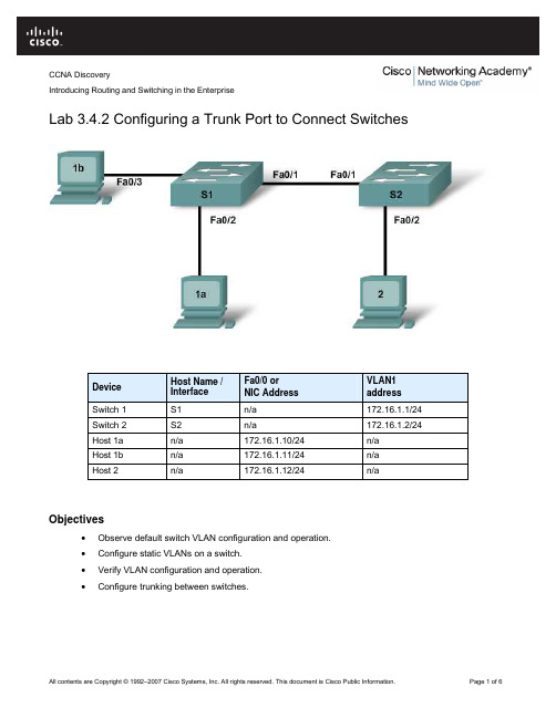
CCNA DiscoveryIntroducing Routing and Switching in the EnterpriseLab 3.4.2 Configuring a Trunk Port to Connect SwitchesDevice Host Name /InterfaceFa0/0 orNIC AddressVLAN1addressSwitch 1 S1 n/a 172.16.1.1/24Switch 2 S2 n/a 172.16.1.2/24Host 1a n/a 172.16.1.10/24 n/aHost 1b n/a 172.16.1.11/24 n/aHost 2 n/a 172.16.1.12/24 n/aObjectives•Observe default switch VLAN configuration and operation.•Configure static VLANs on a switch.•Verify VLAN configuration and operation.•Configure trunking between switches.Background / PreparationThis lab focuses on the basic VLAN configuration of the Cisco 2960 switch (or similar) using Cisco IOS commands. The information in this lab applies to other switches; however, command syntax may vary.Depending upon the switch model, the interface designations may differ. For example, modular switches have multiple slots; therefore, the Fast Ethernet ports may be Fast Ethernet 0/1 or Fast Ethernet 1/1, depending on the slot and port.The following resources are required:•Two Cisco 2960 switches or equivalent switches•Two Windows-based PCs with a terminal emulation program•At least one RJ-45-to-DB-9 connector console cable to configure the switch and the router•Three straight-through Ethernet cables to connect from the PCs to the switches•One crossover Ethernet cable to connect S1 to S2NOTE: Make sure that the routers and the switches have been erased and have no startup configurations.Instructions for erasing both switch and router are provided in the Lab Manual, located on AcademyConnection in the Tools section.Step 1: Connect the equipmenta. Connect Switch 1 Fa0/1 interface to Switch 2 Fa0/1 interface with a crossover cable.b. Connect Host 1a Ethernet interface with a straight-through cable to Switch 1 Fa0/2 interface.c. Connect Host 1b Ethernet interface with a straight-through cable to Switch 1 Fa0/3 interface.d. Connect Host 2 Ethernet interface with a straight-through cable to Switch 2 Fa0/2 interface.e. Connect a PC with a console cable to perform configurations on the router and switches.f. Configure IP addresses on the hosts as shown in the chart.Step 2: Perform basic configuration of Switch 1 and Switch 2a. Connect a PC to the console port of the switches to perform configurations using a terminal emulationprogram.b. Configure Switch 1 with a hostname and console, Telnet, and privileged passwords according to thetable diagram. Save the configuration.c. Configure Switch 2 with a hostname and console, Telnet, and privileged passwords according to thetable diagram. Save the configuration.Step 3: Configure host PCsConfigure the host PCs according to the information in the table and diagram.Step 4: Verify default VLAN configuration and connectivitya. When directly connecting some switches, as in this lab, the switch ports automatically configurethemselves for trunking. To prevent this, manually configure the switch ports for normal operation onS1 and S2.S1(config)#interface fa0/1S1(config-if)# S2(config)#switchport mode accessinterface fa0/1S2(config-if)#switchport mode accessb. Verify default VLAN configurations on both switches with the show vlan command.S1#show vlanS2#show vlanIs every switch port assigned to a VLAN? ____________Which VLAN do the ports appear in? ____________Should any host or switch be able to ping any other host or switch at this time? ____________c. Verify this by pinging from Host 1a to all the other hosts and switches.Are all the pings successful? ____________Step 5: Create and verify VLAN configurationa. Create and name VLANs 2 and 3 on both switches.S1(config)#vlan 2S1(config-vlan)#name fredS1(config-vlan)#exitS1(config)#vlan 3S1(config-vlan)#name wilmaS1(config-vlan)#exitS2(config)#vlan 2S2(config-vlan)#name fredS2(config-vlan)# S2(config)#exitvlan 3S2(config-vlan)#name wilmaS2(config-vlan)#exitb. Assign switch ports to VLANs. The ports connecting Hosts 1a and 2 will be assigned to VLAN 2 andthe port connecting Host 1b will be assigned to VLAN 3. Save the configurations.S1(config)#int fa0/2S1(config-if)#switchport access vlan 2S1(config-if)#exitS1(config)#interface fa0/3S1(config-if)#switchport access vlan 3S1(config-if)#endS1#copy running-config startup-configS2(config)#int fa0/2S2(config-if)#switchport access vlan 2S2(config-if)#S2#copy running-config startup-configendc. Test connectivity between devices.1) Ping from S1 to S2.Are the pings successful? ____________To what VLAN do the management interfaces of S1 and S2 belong? ____________2) Ping from Host 1a to Host 2.Are the pings successful? ____________To what VLAN do Hosts 1a and 2 belong?____________________________________To what VLAN do the Fa0/1 interfaces of the switches belong? ____________If Hosts 1a and 2 belong to the same VLAN, why can’t they ping each other?__________________________________________________________________________3) Ping from host 1a to S1.Are the pings successful? ____________Why can’t Host 1a ping S1?__________________________________________________________________________ Step 6: Configure and verify trunkingTo allow connectivity within multiple VLANs across multiple switches, trunking can be configured. Without trunking, each VLAN requires a separate physical connection between switches.a. Configure trunking on S1 and S2. Port Fa0/1 on S1 is already connected to port Fa0/1 on S2.S1(config)#int Fa0/1S1(config-if)#switchport mode trunkS1(config-if)#endS2(config)#int Fa0/1S2(config-if)#switchport mode trunkS2(config-if)#endb. Verify the creation of the trunk with the show interfaces trunk command.S1#show interfaces trunkS2#show interfaces trunkDo the trunk interfaces appear in the output? _______________What VLAN is set as the native VLAN? _______________What VLANs are allowed to communicate over the trunk? _______________c. View the VLAN configuration on both switches with the show vlan command.S1#show vlanS2#show vlanDo the S1 and S2 Fa0/1 interfaces appear in a VLAN? Why or why not?__________________________________________________________________________d. Retest the connectivity between devices.1) Ping from S1 to S2.Are the pings successful? ____________2) Ping from Host 1a to Host 2.Are the pings successful? ____________3) Ping from Host 1b to Host 2.Are the pings successful? ____________4) Ping from Host 1a to S1.Are the pings successful? ____________e. The ping test should show that devices that belong to the same VLAN can now communicate witheach other across switches, but devices in different VLANs cannot communicate with each other.What would have to be configured to allow devices in different VLANs to communicate with eachother?______________Step 7: Observe the default trunking behavior of switchesa. Previously in this lab, the Fa0/1 interfaces on the switches were manually configured for trunking.Remove that configuration with the no switchport mode trunk command.S1(config)#int Fa0/1S1(config-if)#no switchport mode trunkS1(config-if)#endS2(config)#int Fa0/1S2(config-if)#no switchport mode trunkS2(config-if)#endb. View the trunking status of the switch ports.S1#show interfaces trunkS2#show interface trunkAre Fa0/1 on S1 and S2 in trunking mode?____________What trunking mode did they default to?____________What trunking encapsulation did they default to?____________Step 8: Reflectiona. Why would trunking be configured in a network?________________________________________________________________________________________________________________________________________________________________________________________________________________________________________________________________________________________________________________________________b. Does trunking allow for communication between VLANS?________________________________________________________________________________c. With no configuration, from which VLAN are frames forwarded across the trunk without VLAN taggingadded?________________________________________________________________________________。
思科实验报告
思科实验报告思科实验报告引言:在当今信息化时代,网络技术的发展已经成为推动社会进步的重要力量。
作为全球领先的网络技术公司,思科(Cisco)一直致力于推动网络技术的创新与应用。
本实验报告旨在通过对思科实验的探索与研究,深入了解思科在网络领域的技术和产品。
一、思科的背景与发展思科成立于1984年,总部位于美国加利福尼亚州圣何塞。
作为全球最大的网络技术公司之一,思科在网络设备、软件和服务领域占据重要地位。
公司的发展历程中,不仅推动了互联网的普及和发展,还为各行各业提供了全面的网络解决方案。
二、思科的技术创新1. 路由器技术思科的路由器技术是其最为知名和核心的创新之一。
路由器作为网络的核心设备,负责将数据包从源地址传输到目标地址。
思科的路由器产品具有高性能、高可靠性和安全性强的特点,能够满足不同规模和需求的网络环境。
2. 交换机技术交换机是构建局域网的重要设备,用于实现局域网内部的数据传输。
思科的交换机产品采用了先进的交换技术,能够提供高速、可靠的数据传输,同时支持灵活的网络管理和安全控制。
3. 无线技术随着移动互联网的普及,无线技术的发展变得越来越重要。
思科在无线技术领域也有着丰富的经验和创新成果。
其无线解决方案可以满足不同场景下的无线通信需求,提供稳定、高速的无线网络连接。
4. 安全技术网络安全是当前互联网发展中的一个重要问题。
思科在网络安全领域拥有丰富的经验和技术实力。
其安全产品和解决方案能够提供全面的网络安全保护,包括防火墙、入侵检测系统、虚拟专用网络等。
三、思科的产品应用思科的产品广泛应用于各个行业和领域,为用户提供了全面的网络解决方案。
以下是一些典型的应用案例:1. 企业网络思科的路由器、交换机和安全产品被广泛应用于企业网络中,为企业提供高效、稳定和安全的网络连接,支持企业的业务发展和运营管理。
2. 云计算和数据中心思科的网络设备和解决方案在云计算和数据中心领域具有重要应用。
通过思科的技术支持,云计算和数据中心能够提供高性能、高可靠性和高安全性的服务。
最新思科实训心得报告范文(18篇)

最新思科实训心得报告范文(18篇)(实用版)编制人:__________________审核人:__________________审批人:__________________编制单位:__________________编制时间:____年____月____日序言下载提示:该文档是本店铺精心编制而成的,希望大家下载后,能够帮助大家解决实际问题。
文档下载后可定制修改,请根据实际需要进行调整和使用,谢谢!并且,本店铺为大家提供各种类型的实用资料,如工作总结、工作报告、党团范文、工作计划、演讲稿、活动总结、行政公文、文秘知识、作文大全、其他资料等等,想了解不同资料格式和写法,敬请关注!Download tips: This document is carefully compiled by this editor.I hope that after you download it, it can help you solve practical problems. The document can be customized and modified after downloading, please adjust and use it according to actual needs, thank you!Moreover, our store provides various types of practical materials for everyone, such as work summaries, work reports, Party and Youth League model essays, work plans, speeches, activity summaries, administrative documents, secretarial knowledge, essay summaries, and other materials. If you want to learn about different data formats and writing methods, please stay tuned!最新思科实训心得报告范文(18篇)报告范文的写作过程要注重事实的真实性,对于报告中所涉及的数据、资料要有准确的来源和证明。
- 1、下载文档前请自行甄别文档内容的完整性,平台不提供额外的编辑、内容补充、找答案等附加服务。
- 2、"仅部分预览"的文档,不可在线预览部分如存在完整性等问题,可反馈申请退款(可完整预览的文档不适用该条件!)。
- 3、如文档侵犯您的权益,请联系客服反馈,我们会尽快为您处理(人工客服工作时间:9:00-18:30)。
内蒙古科技大学信息工程学院计算机系《计算机网络》实验报告
说明:
1、每个实验项目填写一份实验报告,电子版命名方式为:学号姓名项目号.doc。
例如:1167111182张三3.doc表示张三做的第3个项目的实验报告。
2、实验报告电子版应该在实验后一周内由学习委员收齐后存放在一个文件夹下,文件夹命名方式为:软件12-1班3,表示软件12-1班第3个项目的实验报告,压缩。
第一时间发送给任课教师。
必须以班级为单位上交。
3、任课教师要求在收到实验报告的一周内进行批阅,并给出成绩及评语。
4、实验报告电子版由任课教师保存。
5、表格宽度可以根据实际情况伸缩。
