error detection1
NandFlash驱动编写知识详解与坏块管理
【Nand Flash驱动编写之前要了解的知识】1.硬件特性:【Flash的硬件实现机制】Flash全名叫做Flash Memory,属于非易失性存储设备(Non-volatile Memory Device),与此相对应的是易失性存储设备(Volatile Memory Device)。
关于什么是非易失性/易失性,从名字中就可以看出,非易失性就是不容易丢失,数据存储在这类设备中,即使断电了,也不会丢失,这类设备,除了Flash,还有其他比较常见的入硬盘,ROM等,与此相对的,易失性就是断电了,数据就丢失了,比如大家常用的内存,不论是以前的SDRAM,DDR SDRAM,还是现在的DDR2,DDR3等,都是断电后,数据就没了。
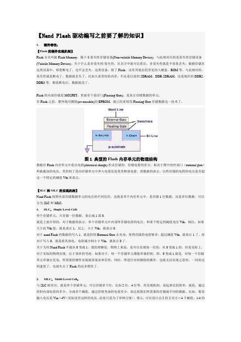
Flash的内部存储是MOSFET,里面有个悬浮门(Floating Gate),是真正存储数据的单元。
在Flash之前,紫外线可擦除(uv-erasable)的EPROM,就已经采用用Floating Gate存储数据这一技术了。
图1.典型的Flash内存单元的物理结构数据在Flash内存单元中是以电荷(electrical charge) 形式存储的。
存储电荷的多少,取决于图中的外部门(external gate)所被施加的电压,其控制了是向存储单元中冲入电荷还是使其释放电荷。
而数据的表示,以所存储的电荷的电压是否超过一个特定的阈值Vth来表示。
【SLC和MLC的实现机制】Nand Flash按照内部存储数据单元的电压的不同层次,也就是单个内存单元中,是存储1位数据,还是多位数据,可以分为SLC和MLC:1.SLC,Single Level Cell:单个存储单元,只存储一位数据,表示成1或0.就是上面介绍的,对于数据的表示,单个存储单元中内部所存储电荷的电压,和某个特定的阈值电压Vth,相比,如果大于此Vth值,就是表示1,反之,小于Vth,就表示0.对于nand Flash的数据的写入1,就是控制External Gate去充电,使得存储的电荷够多,超过阈值Vth,就表示1了。
计算机网络课件 Lec-10
preamble
dest. address
source address
data (payload)
CRC
preamble:
7 bytes with pattern 10101010 followed by one byte with pattern 10101011
used to synchronize receiver, sender clock rates
error detected: frame is dropped
type
preamble
dest. address
source address
data (payload)
CRC
Link Layer 5-55
Ethernet: unreliable, connectionless
connectionless: no handshaking between sending and receiving NICs
common MAC protocol and frame format different speeds: 2 Mbps, 10 Mbps, 100 Mbps, 1Gbps,
10G bps different physical layer media: fiber, cable
application transport network
switching: A-to-A’ and B-to-B’ can transmit simultaneously, without collisions
A
C’
B
61 2
5 43
B’
C
A’
switch with six interfaces (1,2,3,4,5,6)
10_2-10_Error_Correction

• Which has less overhead?
– It still depends! We need to know more about the errors
Computer Networks 18
Detection vs. Correction (2)
1. Assume bit errors are random
• Error correction:
– Needed when errors are expected – Or when no time for retransmission
• Error detection:
– More efficient when errors are not expected – And when errors are large when they do occur
• Error detection:
– Need 32? check bits per message plus 1000 bit resend 2/1000 of the time – Overhead:
Computer Networks 20
Detection vs. Correction (4)
Computer Networks 10
Hamming Code (5)
• Example, continued
0 1 0 0 1 0 1
1 2 3 4 5 6 7
p1= p4= Syndrome = Data =
Computer Networks
p2=
11
Hamming Code (6)
• Example, continued
0 1 0 0 1 0 1
type i error
type i errorTypeIError:在统计学中,Type I Error或错误定义为错误地拒绝正确的零假设。
它是指统计检验时,对实际上没有发生的研究结论作了正确的结论,这种情况称为错误定义1(Type I Error)。
一般来说,Type I Error是采用错误的零假设而拒绝正确的零假设的结果。
它也被称为“假正(False Positive)”错误,也就是表示某一问题存在,实际上却不是。
Type I Error源于统计学家R.A.Fisher在1925年发表的著作《论实验设计》中。
在书中,他提到了Type I Error,建议在统计学家构建概率检验时,应该把Type I Error的可能性降到最低。
Type I Error的研究把它看作是检验的失误,即在实际检验中,误报某一零假设为真的情况。
为了消除这种失误,Fisher提出了阈值α,规定这个值必须小于0.05,即只有当检验出来的概率p小于0.05时,才可以表示这个实验结果为真。
有时,研究人员在进行实验时,会存在把假的零假设误认为是真的的情况,这种情况就是Type I Error。
Type I Error的产生可能是因为研究人员没有选择合适的统计方法或者统计检验没有应用得当。
一般来说,Type I Error是统计检验的缺点,即检验结果有可能假定某一实验结果为真而实际上并不是真实的,这就是Type I Error。
正确的统计检验可以有效避免Type I Error的出现,避免研究中出现错误结果。
因此,要有效避免Type I Error产生,需要注意以下几点:(1)在选择统计检验方法时,应该有足够的统计学基础,选择最适合自己研究的方法。
(2)避免统计检验出现明显偏差,即把实际检验结果和理论结果差别较大。
(3)熟悉统计检验的一般原理,如检验的置信度以及错误的概率大小。
(4)把统计检验的阈值α,设定在0.05以下,这样就可以尽可能减少Type I Error的发生。
stablediffusion error code1
stablediffusion error code1英文版Stablediffusion error code1When encountering error code1 in the Stablediffusion system, it is important to understand what this code means and how to address it. Error code1 typically indicates a communication error between the server and the client, resulting in data not being transmitted properly. This can lead to issues with stability and performance of the system.To troubleshoot error code1, first check the network connection between the server and the client. Ensure that both devices are properly connected to the network and that there are no issues with the internet connection. If the network connection is fine, then the next step is to check the server settings to ensure that they are properly configured.If the server settings are correct, then the issue may lie with the client-side settings. Check the client configuration to make sure that it is set up correctly and that there are no conflicts with other software or devices. It may also be helpful to restart both the server and the client to see if that resolves the issue.If none of these steps resolve the error code1, it may be necessary to contact technical support for further assistance. They will be able to provide additional troubleshooting steps and help identify the root cause of the issue. By addressing error code1 promptly and effectively, you can ensure the stability and performance of your Stablediffusion system.中文版当在Stablediffusion系统中遇到error code1时,重要的是要理解这个代码的含义以及如何解决它。
detected io error
主题:探测输入输出错误内容:1. 输入输出错误的含义和影响输入输出错误(IO error)指的是在数据的输入输出过程中出现的错误。
这种错误可能会导致数据丢失、损坏或者程序中断,对计算机系统的稳定性和可靠性造成严重影响。
2. IO error的常见原因IO error可能由多种原因引起,包括但不限于硬件故障、软件错误、数据传输中断、文件系统损坏等。
在检测和解决IO error时,需要全面考虑可能的原因,并进行逐一排查。
3. IO error的检测方法为了及时发现和解决IO error,可以采用以下几种检测方法:- 监控系统日志:定期查看系统日志,关注是否有IO error相关的报警或异常信息。
- 使用专业工具:一些专业的系统检测工具能够实时监控系统的输入输出情况,发现可能存在的IO error。
- 运行自检程序:一些操作系统或存储设备提供了自检程序,可以通过运行这些程序来检测系统的输入输出是否正常。
4. IO error的解决方法对于已经发现的IO error,需要及时采取措施进行解决,可以采用以下方法:- 检查硬件设备:首先需要排查硬件设备是否存在故障,包括硬盘、内存、主板等,确保设备正常工作。
- 修复数据文件:如果出现了文件系统损坏导致的IO error,需要采用相应的数据修复工具对文件系统进行修复。
- 更新驱动程序:有时候IO error可能是由于驱动程序不兼容或者过时引起的,及时更新驱动程序可能有助于解决IO error。
- 重新连接设备:如果是外部的存储设备出现了IO error,可以尝试重新连接设备或者更换连接线缆,看是否能够解决问题。
5. 预防IO error的方法在日常的系统维护中,应该采取一定的预防措施来减少IO error的发生:- 定期备份数据:定期备份数据是防止数据丢失的最有效方法,可以在发现IO error后迅速恢复数据。
- 定期维护设备:定期维护计算机设备,包括清理灰尘、更新系统补丁、优化系统设置等,可以减少IO error的发生。
纹理物体缺陷的视觉检测算法研究--优秀毕业论文
摘 要
在竞争激烈的工业自动化生产过程中,机器视觉对产品质量的把关起着举足 轻重的作用,机器视觉在缺陷检测技术方面的应用也逐渐普遍起来。与常规的检 测技术相比,自动化的视觉检测系统更加经济、快捷、高效与 安全。纹理物体在 工业生产中广泛存在,像用于半导体装配和封装底板和发光二极管,现代 化电子 系统中的印制电路板,以及纺织行业中的布匹和织物等都可认为是含有纹理特征 的物体。本论文主要致力于纹理物体的缺陷检测技术研究,为纹理物体的自动化 检测提供高效而可靠的检测算法。 纹理是描述图像内容的重要特征,纹理分析也已经被成功的应用与纹理分割 和纹理分类当中。本研究提出了一种基于纹理分析技术和参考比较方式的缺陷检 测算法。这种算法能容忍物体变形引起的图像配准误差,对纹理的影响也具有鲁 棒性。本算法旨在为检测出的缺陷区域提供丰富而重要的物理意义,如缺陷区域 的大小、形状、亮度对比度及空间分布等。同时,在参考图像可行的情况下,本 算法可用于同质纹理物体和非同质纹理物体的检测,对非纹理物体 的检测也可取 得不错的效果。 在整个检测过程中,我们采用了可调控金字塔的纹理分析和重构技术。与传 统的小波纹理分析技术不同,我们在小波域中加入处理物体变形和纹理影响的容 忍度控制算法,来实现容忍物体变形和对纹理影响鲁棒的目的。最后可调控金字 塔的重构保证了缺陷区域物理意义恢复的准确性。实验阶段,我们检测了一系列 具有实际应用价值的图像。实验结果表明 本文提出的纹理物体缺陷检测算法具有 高效性和易于实现性。 关键字: 缺陷检测;纹理;物体变形;可调控金字塔;重构
Keywords: defect detection, texture, object distortion, steerable pyramid, reconstruction
II
CS5381-KZZ;CS5381-KSZ;CS5381-KZZR;CS5381-KSZR;中文规格书,Datasheet资料

192 kHz ! 260 mW Power Consumption ! High-Pass Filter or DC Offset Calibration ! Supports Logic Levels between 5 and 2.5 V ! Differential Analog Architecture ! Low-Latency Digital Filtering ! Overflow Detection ! Pin-Compatible with the CS5361
Analog Supply 5V
Digital Supply 3.3 V to 5 V
Interface Supply 2.5 V to 5 V
Differential Inputs
Differential Inputs
Internal Voltage Reference
Switch-Cap ADC
Switch-Biblioteka ap ADCDigital Filters
Digital Filters
Level Translator
cudnn error code1
CUDNN错误代码解析CUDNN是NVIDIA推出的一套深度学习库,它提供了高度优化的深度学习算法实现,可以在基于NVIDIA GPU的系统上进行加速运算。
然而,有时在使用CUDNN库时,可能会遇到一些错误代码,比如错误代码1。
本文将对CUDNN错误代码1进行解析,帮助读者更好地理解和处理这一错误。
1. CUDNN错误代码1的含义在CUDNN中,错误代码1代表CUDNN_STATUS_NOT_INITIALIZED,即未初始化CUDNN库。
这个错误通常发生在用户在调用CUDNN相关函数之前未初始化CUDNN库的情况下。
这可能是因为用户在使用CUDNN之前没有正确初始化CUDNN库,或者在使用CUDNN之前先初始化了其他的深度学习库,导致CUDNN库未能正确初始化。
2. 解决CUDNN错误代码1的方法要解决CUDNN错误代码1,可以采取以下几种方法:2.1 确保正确初始化CUDNN库在使用CUDNN之前,用户需要确保正确初始化CUDNN库。
在使用CUDNN相关函数之前,可以调用cudnnCreate()函数来初始化CUDNN库,确保CUDNN库已经成功初始化。
2.2 检查其他深度学习库的初始化情况如果用户在使用CUDNN之前先初始化了其他的深度学习库,可能会导致CUDNN库未能正确初始化。
在调用CUDNN相关函数之前,需要确保其他深度学习库已经正确初始化,或者在使用CUDNN之前先释放其他深度学习库的资源。
2.3 检查CUDNN版本和GPU驱动版本有时CUDNN错误代码1的出现也可能与CUDNN版本或GPU驱动版本有关。
用户可以尝试升级CUDNN版本或GPU驱动版本,或者降级CUDNN版本或GPU驱动版本,来解决这一问题。
3. 避免CUDNN错误代码1的发生为了避免CUDNN错误代码1的发生,用户需要在使用CUDNN之前仔细检查和确认CUDNN库的初始化情况,确保CUDNN库已经成功初始化。
需要注意不要在使用CUDNN之前先初始化其他的深度学习库,避免因为资源冲突而导致CUDNN库未能正确初始化。
DS2208数字扫描器产品参考指南说明书
-05 Rev. A
6/2018
Rev. B Software Updates Added: - New Feedback email address. - Grid Matrix parameters - Febraban parameter - USB HID POS (formerly known as Microsoft UWP USB) - Product ID (PID) Type - Product ID (PID) Value - ECLevel
-06 Rev. A
10/2018 - Added Grid Matrix sample bar code. - Moved 123Scan chapter.
-07 Rev. A
11/2019
Added: - SITA and ARINC parameters. - IBM-485 Specification Version.
No part of this publication may be reproduced or used in any form, or by any electrical or mechanical means, without permission in writing from Zebra. This includes electronic or mechanical means, such as photocopying, recording, or information storage and retrieval systems. The material in this manual is subject to change without notice.
abnormality_detection1
A Particle Filtering Approach to Abnormality Detection in Nonlinear Systems and its Application to Abnormal ActivityDetectionNamrata Vaswani,Rama ChellappaCenter for Automation ResearchDepartment of Electrical and Computer EngineeringUniversity of Maryland,College ParkMD20742,USAnamrata,rama@AbstractWe study abnormality detection in partially observed nonlinear dynamic systems tracked using particlefilters.An‘abnormality’is defined as a change in the system model,which could be drastic or gradual,with the parameters of the changed system unknown.If the change is drastic the particle filter will lose track rapidly and the increase in tracking error can be used to detect the change. In this paper we propose a new statistic for detecting‘slow’changes or abnormalities which do not cause the particlefilter to lose track for a long time.In a previous work,we have proposed a partially observed nonlinear dynamical system for modeling the configuration dynamics of a group of interacting point objects and formulated abnormal activity detection as a change detection problem. We show here results for abnormal activity detection comparing our proposed change detection strategy with others used in literature.1IntroductionIn many practical problems arising in quality control or surveillance problems like abnormal activity detection,the underlying system in its normal state can be modeled as a parametric stochastic model (which may be linear or nonlinear).In most cases,the observations are noisy(making the system partially observed)and the transformation between the observation and the state may again be linear or nonlinear.Such a system,in the most general case,forms a Partially Observed Non-Linear Dynamical (PONLD)system which can be tracked using a particlefilter[1].An‘abnormality’constitutes a change, which could be drastic or gradual,in the system model,with the parameters of the system model after the change unknown.If the change in the system is‘drastic’(or abrupt)the particlefilter will lose track rapidly and the increase in tracking error can be used to detect the change[2].In this paper we propose a new strategy for detecting‘slow’(gradual)changes or abnormalities in partially observed nonlinear systems which do not cause the particlefilter to lose track for very long and whose parameters are unknown,and show its application to abnormal activity detection.In a previous work[3],we have modeled the changing configuration of a group of moving point objects(an“activity”)as a moving deformable shape in.We have proposed a PONLD system to model an activity with the learnt shape deformation and motion models forming the system model and the measurement noise in the object locations(configuration space)forming the observation model.The mapping from state(shape+motion) space to observation(configuration)space is nonlinear.In this paper,we apply our proposed change detection strategy for abnormal activity(suspicious behavior)detection in this framework and compare its performance,for both slow and drastic abnormalities,with other statistics used in literature.1.1Previous WorkOnline detection of changes for partially observed linear dynamical systems has been studied exten-sively.For known changed system parameters the CUSUM[4]algorithm can be used directly.The CUSUM algorithm uses as change detection statistic,the maximum(taken over all previous time in-stants)of the likelihood ratio assuming change occurred at time,i.e.Extended Kalman Filtering[5]and change detection methods for linear systems are the main tools for change detection[4].Linearization techniques are computationally efficient but are not always applica-ble(require a good initial guess at each time step and hence not robust to noise spikes).[6]is an attempt to use a Particle Filtering(PF)approach for abrupt change detection in Partially Observed Non-Linear Dynamical(PONLD)systems without linearization.It uses knowledge of the parameters of the changes system and defines a modification of the CUSUM change detection statistic that can be evaluated recursively.It runs a sequence(for different)of PF’s to evaluate the probability of the observations given that the change occurred at time and compares each with the observations’probability evaluated using a PF which assumes that no change occurred.Another statistic commonly used for abrupt change detection in partially observed systems and which does not require knowledge of changed system parameters is tracking error[2].Tracking error is the distance(usually Euclidean distance)between the current observation and its prediction based on past observations.Another class of approaches(eg.see[7,8])used extensively with particlefilters uses a discrete state variable to denote the mode that the system is operating in.This is typically used when the system can operate in multiple modes each associated with a different system and/or observation model.The mode variable’s transition between states is governed by which mode maximizes the likelihood of the observations.But this approach also assumes known change parameters.Particlefiltering(PF)[9]also known as the sequential Monte Carlo method[10]or condensation algorithm[11]provides afinite dimensional approximate solution to the conditional density of the state given past observations.In this paper,we use a PF(described in section3)to track the PONLD system. The PF provides at each time instant,an-sample monte carlo estimate of the poterior distribution of the state of the system,given observations upto time.We propose to use as a change detection statistic,the expectation under this posterior state distribution of the log of the a-priori pdf of the state at time and we call this statistic”Expected Log Likelihood”or ELL.This is discussed in section4. In section5,we prove convergence of the Huber M-estimate[12]of this statistic,evaluated using the posterior distribution estimated by the PF,to its true value.Also,to be able to detect both slow and drastic changes,we propose to use a combination of ELL and tracking error.Finally in section6we show results for abnormal activity detection using ELL,tracking error,observation likelihood,, and the combined ELL-tracking error strategy and discuss future work in section7.2Problem Statement and AssumptionsGiven a partially observed nonlinear dynamic(PONLD)system[13]with an valued state process and an valued observation process,the aim is to detect a change in the system model(model for).The system(or state)process for the normal system is assumed to be a Markov process with state transition kernel and the observation process is defined bywhere is an i.i.d.noise process and is in general a nonlinear function.The prior initial state distribution denoted by,the observation likelihood denoted by and the state transition kernel are known.We assume in this work that the prior is absolutely continuous(w.r.t.to the Lebesgue measure)i.e.it admits a density(pdf),the transition kernel is Feller[13]and also absolutely continuous for all values of and for all.Also the observation likelihood is absolutely continuous i.e.it admits a density which is a continuous and everywhere positive function.Abnormality detection in a PONLD system is posed as a change detection problem with parameters of the changed system unknown.If the abnormality is a drastic one,it would cause the PF to lose track (tracking error will increase)and hence will get detected.But in a lot of cases,the abnormality is a slow change that does not cause the PF to lose track for a long time(there will be a large detection delay if tracking error is used)and this is the problem that we address here.To be specific,the problem is to detect a gradual change in the system model i.e.detect with minimum delay,the time instantwhen the state starts following a different system model with transition kernel which is unknown.3Particlefiltering(PF)The particlefilter[13]is a recursive algorithm which produces at each time,a cloud of particles, ,whose empirical measure closely“follows”the posterior distribution of the state given past observations(denoted by in the rest of the paper).It starts with sampling times from the initial state distribution to approximate it by,the predictionstep samples the new state from the distribution.Thus the empirical distribution of this new cloud of particles,.. Note that both and approximate but the resampling step is used because it increases the sampling efficiency by eliminating samples with very low weights.4Change/Abnormality DetectionFirst let us define some notation.The integral of a function w.r.t.a measure is denoted by with(1)Given the prior initial state distribution and the transition kernel,the prior state distribution at any time is.Since the transition kernel is absolutely continuous,this state distribution admits a pdf.In a lot of cases(for example if the system model is linear Gaussian with Gaussian initial state pdf)it is possible to define the pdf in closed form.Now,if the system were fully observed,one could evaluate from the observation and then (negative log-likelihood of the state coming from a normal system)could be used as a change detection statistic;the negative log-likelihood of the state of the changed or abnormal system would be smaller than that of the normal system.But for a partially observed system we can only approximate(using a PF)the posterior distribution of the state given past observations,by.The negative log-likelihood of state coming from a normal system can now be replaced by its expectation under the posterior distribution of the state.Thus for the partially observed system tracked using a PF,we propose to use as the change detection statistic,the expected log-likelihood(ELL),,approximated by. It is interesting to note that ELL is also the Kerridge inaccuracy[14]between.This is approximated using thePF as.The inaccuracy between the posterior state distribution corresponding to normal observations and the prior will be smaller than that between the posterior corresponding to abnormal observations and the prior.Kerridge inaccuracy can also be interpreted as the average length of code designed for rather than[15].The advantage of this statistic over others used in literature(for PONLD systems tracked using PF’s) like tracking error[2]or log-likelihood of current observation given past observations[6]is that it can detect slow changes much better.Consider as an example to motivate our approach,a PONLD system with a linear Gaussian system model i.e..is i.i.d.zero mean Gaussian noise,is a zero mean Gaussian,so that is also a zero mean Gaussian density.Let us assume that the abnormality causes the system model to change to,whereis a small constant bias added to the state or part of the state vector.If the bias added along a direction is small or comparable to the noise variance along that direction,it will get tracked correctly by the PF and hence tracking error will not show a significant change.But a systematically increasing bias along certain directions will cause the mean of the posterior distribution of the state to increase to a significantly nonzero value within a few time steps,thus causing the Kerridge inaccuracy between the posterior and the normal system pdf to increase.For such a problem,ELL(or Kerridge inaccuracy)will detect the abnormality much faster than tracking error.Now,if the abnormality/change is a drastic one,it will cause the PF to lose track quite rapidly(the number of particles,,is afinite number,and so there will be very few particles around the expected value of the abnormal state),thus causing the tracking error to show a sudden increase which can be used for detecting an abrupt change.Due to the same reason,the estimate of the posterior distribution in this case is no longer reliable and hence the ELL evaluated with it will also be inaccurate.For this case tracking error is a more reliable change detection statistic.Hence a robust change detection strategy which can detect both slow and drastic changes with minimum delay would be to use both tracking error and ELL to detect a change;if either one exceeds its respective threshold then a change is declared.5Convergence of ApproximationLet be a probability space,then the sequence is a sequence of random measures, and is a deterministic probability measure.denotes the set ofprobability measures over the Borel sigma algebra on.Theorem1[13]:The sequence of(empirical)posterior state distributions estimated using a PF (that satisfies certain smoothness assumptions discussed in[13])converges weakly to the true posterior ,P-a.s.,i.e.P-a.s.(2) where denotes the set of continuous bounded functions on.First note that the PF used in this work satisfies the assumptions of[13]:As discussed earlier in section2, the observation likelihood,is a continuous and everywhere positive funciton and the transition kernel is Feller.The multinomial resampling step(described in section3)produces unbiased samples from with variance of the weights estimated from the samples bounded by(so it goes to zero as). Now,the negative log likelihood of state is an unbounded function while the theorem stated above works for bounded continuous functions.But since it is a non-negative function, we can use the standard mathematical analysis trick of approximating it by a sequence of increasing bounded functions which will converge to,i.e.define(3)Then we have.Now,is a continuous bounded function and so we can use theorem1with to prove convergence of to,P-a.s.,as, i.e.P-a.s,(4) Since is a sequence of non-negative increasing functions that converge pointwise to,we can use Monotone Convergence Theorem([16],page87)to prove convergence of to,i.e.(5) Combining equations(4)and(5),we getCorollary1P-a.s(6)or that the error between the posterior expectation of the bounded approximation of negative log-likelihood of state,evaluated using an-particle PF,and its true value can be made as small as one wants by choosing the bound to be large enough and given the bound,choosing to be large enough.Remark1:Interpreting the above result in terms of Kerridge inaccuracy,we haveslow changes.But a drastic or abrupt change with large enough to track only the normal system,will cause the PF to lose track.Now,if the PF does lose track due to a change,tracking error will detect the change while as long as it is able to track the changing system,the evaluated ELL will increase from its normal value,so that ELL can detect such a change.6Abnormal Activity DetectionIn a previous work[3],we have defined a PONLD system for modeling the configuration dynamics of a group of interacting point objects which we treat as a moving and deforming shape.The shape deformation model and the motion(scale,rotation)model form the system model and the measurement noise in the point object configuration constitutes the observation noise.We have assumed a stationary shape deformation model,and so we are able to learn a single mean shape for the data.We use the tangent space coordinates w.r.t this mean shape[19]as the shape coordinates.Also,since translation is a linear operation,we use a translation normalized configuration vector as the observation vector(thus avoiding the need to have translation as part of the state vector).We give below the equations used for the observation model and for the system model for shape,scale and rotation.6.1Dynamical ModelObservation Modelwhere(9)is a complex vector of observations containing the object locations measurements,is a nonlin-ear function of the state,where is the vector of the tangent coordinates of shape, is the rotation angle,and is the scale.System ModelWe set as detection threshold for a statistic,its maximum value for a normal test ing this threshold we plot the detection delay against the rate of change(walk away velocity)for the three statis-tics.We do this for in3(a),(b),(c).Now detection delay using ELL is least except when the change is very drastic(velocity=16,32)where tracking error or Obs.likelihood perform better. The criterion for choosing a change detection statistic and its threshold is to minimize the detection delay for afixed mean time between false alarms[4].Since we are assuming unknown change param-eters,we plot the average delay in detecting abnormality(averaged over different change rates)against the mean time between false alarms.We do this infigure4(a),(b),(c)for.As can be seen from thefigures,ELL has the best average detection delay performance.But we know from the previousfigure that tracking error has better performance for drastic abnormalities.Thus as discussed in section4,we combine ELL and tracking error,i.e.we declare a change if either ELL or tracking error exceed their respective thresholds.To choose an operating point,we vary thresholds for both ELL and tracking error and plot the average detection delay versus mean time between false alarms.Each broken green line plot plots the detection delay for ELL thresholdfixed,tracking error threshold varying.As is evident fromfigure4,for most values of mean time between false alarm,we can obtain an operating point with this combined strategy that has lower detection delay than either ELL or tracking error alone.7Discussion and Future WorkNow[6]defines a CUSUM like likelihood ratio based statistic for change detection.But in our problem, the parameters of the changed system are unknown and so we cannot define the probability of observa-tions under the changed system and hence the likelihood ratio cannot be defined.One could try to adapt the idea to the case of unknown parameters by trying to usewhere is the probability of the observations under the normal system hypothesis and is a normalcy threshold for the observation ing this kind of a statistic will detect the change time more accurately and have lesser false alarms than just the current‘Obs.likelihood’as defined by us but it is computationally more complex.Also,it is not clear how to set the thresholds.As part of future work,one could attempt to define a CUSUM like statistic for ELL of state given observations i.e.define and compare its performance with defined above.We can set to be the expected value over observation sequences of the ELL at time,(a)(b)Figure 1:(a):A ‘normal activity’frame with 4people,(b):Abnormality:One person walking away in a weirddirection.,which is equal to the expected value underof(which is the entropyof).For the case of Gaussian prior this simplifies to a constant times the dimensionality of the datai.e..For small observation noises,one could assume the system to be fully observed and replace ELLby log likelihood of.It would be interesting to study at what observation noise,thefully observed assumption starts to fail.Finally,we hope to compare performance of the change detec-tion statistics for different kinds of abnormalities in this and other applications and also for non-white and non-Gaussian observation noise.In non-Gaussian noise,one interesting case would be how to dis-tinguish outlier observations caused due to say Cauchy noise from an abnormality.For such a case,a sequence based statistic likeorwould prove useful.Another interesting problem would be switchingbetween a couple of known modes using a discrete mode variable as in [7,8]and defining the sequence to be abnormal only if the posterior state distribution is far from the priors corresponding to all the modes.We have studied the change detection problem in more detail in a recent work [18],which analyzes the errors in approximating the ELL using a PF optimal for the normal system.It also discusses more rigorously,the complementary behavior of ELL and Obs.Likelihood for change detection.tE L L(a)(b)(c)Figure 2:We show plots of ELL,tracking error and obs.likelihood (in (a),(b),(c)respectively)for normal activityand increasing walk away velocities (abnormal behavior)as a function of time.Abnormality is introduced at and.(a)(b)(c)Figure 3:We plot the detection delay for zero false alarm against the rate of change (walk away velocity)for thethree statistics.(a),(b),(c)are for increasing observation noise.References[1]A.Doucet,N.deFreitas,and N.Gordon,Sequential Monte Carlo Methods in Practice ,Springer,2001.[2]Y .Bar-Shalom and T.E.Fortmann,Tracking and Data Association ,Academic Press,1988.A v e r a g e D e t e c t i o n D e l a y(a)(b)(c)Figure 4:We plot the ROC (detection delay averaged over all rates of change versus mean time between falsealarms)for the three statistics and the green dotted lines are the ROC for combining ELL and tracking error.(a),(b),(c)are for increasing observation noise.[3]N.Vaswani,A.RoyChowdhury,and R.Chellappa,“Activity recognition using the dynamics ofthe configuration of interacting objects,”in IEEE Conference on Computer Vision and Pattern Recognition (CVPR),2003.[4]M.Basseville and I Nikiforov,Detection of Abrupt Changes:Theory and Application ,PrenticeHall,1993.[5]T.Kailath,A.H.Sayed,and B.Hassibi,Linear Estimation ,Prentice Hall,2000.[6]B.Azimi-Sadjadi and P.S.Krishnaprasad,“Change detection for nonlinear systems:A particlefiltering approach,”in American Control Conference ,2002.[7]R.Dearden and D.Clancy,“Particle filters for real-time fault detection in planetary rovers,”.[8]Shaohua Zhou and Rama Chellappa,“Probabilistic human recognition from video,”in EuropeanConference on Computer Vision ,2002,pp.681–697.[9]N.J.Gordon,D.J.Salmond,and A.F.M.Smith,“Novel approach to nonlinear/nongaussian bayesianstate estimation,”IEE Proceedings-F (Radar and Signal Processing),pp.140(2):107–113,1993.[10]P.Fearnhead,“Sequential monte carlo methods infilter theory,”in PhD Thesis,Merton College,Universoty of OXford,1998.[11]M.Isard and A.Blake,“Contour tracking by stochastic propagation of conditional density,”Euro-pean Conference on Computer Vision,pp.343–356,1996.[12]G.Casella and R.Berger,Statistical Inference,Duxbury Thomson Learning,second edition,2002.[13]D.Crisan and A.Doucet,“Convergence of sequential monte carlo methods,”in Technical Report,Cambridge University,2000.[14]D.F.Kerridge,“Inaccuracy and inference,”J.Royal Statist.Society,Ser.B,vol.231961.[15]Rudolf Kulhavy,“A geometric approach to statistical estimation,”in IEEE Conference on Decisionand Control(CDC),Dec.1995.[16]H.L.Royden,Real Analysis,Prentice Hall,1995.[17]LeGland F.and Oudjane N.,“Stability and Uniform Approximation of Nonlinear Filters using theHilbert Metric,and Application to Particle Filters,”Technical report,RR-4215,INRIA,2002.[18]N.Vaswani and R.Chellappa,“Change detection in partially observed nonlinear dynamical sys-tems with change parameters unknown,”in submitted to American Control Conference(ACC), 2004.[19]I.L.Dryden and K.V.Mardia,Statistical Shape Analysis,John Wiley and Sons,1998.。
oneerror指标

OneError是一种用于衡量模型或系统分类准确度的评估指标。
它是指在多分类问题中,只有一个错误分类的样本比例。
具体来说,它衡量了模型将一个样本错误分类为与其真实类别不同的类别的概率。
OneError指标在分类问题中非常重要,因为它能够提供有关模型分类性能的精确度量。
通过计算OneError,可以了解模型在每个类别上的分类准确性,并确定哪些类别特别容易发生错误分类。
OneError指标通常用于机器学习、数据挖掘和模式识别等领域中的分类算法性能评估。
与其他分类准确度指标相比,OneError更具体地关注于错误分类的情况,并提供了更准确的性能评估。
需要注意的是,OneError指标的计算需要完整的类别标签信息,因此它不适用于不平衡数据集或无标签数据集。
此外,OneError指标也不适用于多标签分类问题,因为多标签分类问题中一个样本可能属于多个类别。
希望以上信息对您有帮助,更多相关信息建议咨询机器学习领域的专业人士或查阅相关文献资料。
a painless guide to crc error detection algorithms
目录原文网址/filipg/LINK/F_crc_v3.html (2)2. Introduction: Error Detection (2)3. The Need For Complexity (3)4. The Basic Idea Behind CRC Algorithms (4)5. Polynomial(多项式)Arithmetic (6)Chapter 6 Binary Arithmetic with No Carries (9)Chapter 7 A Fully Worked Example (12)Chapter 8 Choosing A Poly (15)Chapter 9) A Straightforward CRC Implementation (16)Chapter 10 A Table-Driven Implementation (18)Chapter 11 A Slightly Mangled(损坏的) Table-Driven Implementation (22)Chapter 12) "Reflected" Table-Driven Implementations (26)Chapter 13) "Reversed" Polys (28)Chapter 14) Initial and Final Values (29)Chapter 15) Defining Algorithms Absolutely (30)Chapter 16) A Parameterized Model For CRC Algorithms (30)Chapter 17) A Catalog of Parameter Sets for Standards (32)Chapter 18) An Implementation of the Model Algorithm (34)Chapter 19) Roll Your Own Table-Driven Implementation (34)Chapter 20) Generating A Lookup Table (35)Chapter 21) Summary (36)Chapter 22) Corrections (36)Chapter 23) Glossary (36)Chapter 24) References (37)Chapter 25) References I Have Detected But Haven't Yet Sighted (38)原文网址/filipg/LINK/F_crc_v3.html2. Introduction: Error Detection The aim of an error detection technique is to enable the receiver of a message transmitted through a noisy (error-introducing) channel to determine whether the message has been corrupted. To do this, the transmitter constructs a value (called a checksum) that is a function of the message, and appends it to the message. The receiver can then use the same function to calculate the checksum of the received message and compare it with the appended checksum to see if the message was correctly received. For example, if we chose a checksum function which was simply the sum of the bytes in the message mod 256 (i.e. modulo 256), then it might go something as follows. All numbers are in decimal.Message : 6 23 4Message with checksum : 6 23 4 33Message after transmission : 6 27 4 33In the above, the second byte of the message was corrupted(变坏)from 23 to 27 by the communications channel. However, the receiver can detect this by comparing the transmitted checksum (33) with the computer checksum of 37 (6 + 27 + 4). If the checksum itself is corrupted, a correctly transmitted message might be incorrectly identified as a corrupted one. However, this is a safe-side failure. A dangerous-side failure occurs where the messageand/or checksum is corrupted in a manner that results in a transmission that is internally consistent. Unfortunately, this possibility is completely unavoidable and the best that can be done is to minimize its probability by increasing the amount of information in the checksum (e.g. widening the checksum from one byte to two bytes).Other error detection techniques exist that involve performing complex transformations on the message to inject it with redundant(冗长的)information. However, this document addresses only CRC algorithms, which fall into the class of error detection algorithms that leave the data intact(原封不动的)and append a checksum on the end. i.e.:<original intact message> <checksum>3. The Need For ComplexityIn the checksum example in the previous section, we saw how a corrupted message was detected using a checksum algorithm that simply sums the bytes in the message mod 256:Message : 6 23 4Message with checksum : 6 23 4 33Message after transmission : 6 27 4 33A problem with this algorithm is that it is too simple. If a number of random corruptions occur, there is a 1 in 256 chance that they will not be detected. For example:Message : 6 23 4Message with checksum : 6 23 4 33Message after transmission : 8 20 5 33To strengthen the checksum, we could change from an 8-bit register to a16-bit register (i.e. sum the bytes mod 65536 instead of mod 256) so as to apparently reduce the probability of failure from 1/256 to 1/65536(why?因为结果有65536种可能性,不变只占其中一种). While basically a good idea, it fails in this case because the formula used is not sufficiently "random"; with a simple summing formula, each incoming byte affects roughly only one byte of the summing register no matter how wide it is. For example, in the second example above, the summing register could be a Megabyte(兆字节)wide, and the error would still go undetected. This problem can only be solved by replacing the simple summing formula with a more sophisticated formula that causes each incoming byte to have an effect on the entire checksum register.Thus, we see that at least two aspects are required to form a strong checksum function:WIDTHA register width wide enough to provide a low a-priori probability offailure (e.g. 32-bits gives a 1/2^32 chance of failure).CHAOSA formula that gives each input byte the potential to change anynumber of bits in the register.Note: The term "checksum" was presumably used to describe early summing formulas, but has now taken on a more general meaning encompassing more sophisticated algorithms such as the CRC ones. The CRC algorithms to be described satisfy the second condition very well, and can be configured to operate with a variety of checksum widths.4. The Basic Idea Behind CRC AlgorithmsWhere might we go in our search for a more complex function than summing? All sorts of schemes spring to mind. We could construct(建造)tables using the digits of pi, or hash(散列)each incoming byte with all the bytes in the register. We could even keep a large telephone book on-line, and use each incoming byte combined with the register bytes to index a new phone number which would be the next register value. The possibilities are limitless.However, we do not need to go so far; the next arithmetic step suffices(足够). While addition is clearly not strong enough to form an effective checksum, it turns out that division is, so long as the divisor is about as wide as the checksum register.The basic idea of CRC algorithms is simply to treat the message as an enormous binary number, to divide it by another fixed binary number, andto make the remainder from this division the checksum. Upon receipt of the message, the receiver can perform the same division and compare the remainder with the "checksum" (transmitted remainder).Example: Suppose the the message consisted of the two bytes (6,23) as in the previous example. These can be considered to be the hexadecimal number 0617 which can be considered to be the binary number0000-0110-0001-0111. Suppose that we use a checksum register one-byte wide and use a constant divisor of 1001, then the checksum is the remainder after 0000-0110-0001-0111 is divided by 1001. While in this case, this calculation could obviously be performed using common garden variety32-bit registers, in the general case this is messy. So instead, we'll do thedivision using good-'ol long division which you learned in school (remember?). Except this time, it's in binary:...0000010101101 = 00AD = 173 = QUOTIENT____-___-___-___-9= 1001 ) 0000011000010111 = 0617 = 1559 = DIVIDEND DIVISOR 0000.,,....,.,,,----.,,....,.,,,0000,,....,.,,,0000,,....,.,,,----,,....,.,,,0001,....,.,,,0000,....,.,,,----,....,.,,,0011....,.,,,0000....,.,,,----....,.,,,0110...,.,,,0000...,.,,,----...,.,,,1100..,.,,,1001..,.,,,====..,.,,,0110.,.,,,0000.,.,,,----.,.,,,1100,.,,,1001,.,,,====,.,,,0111.,,,0000.,,,----.,,,1110,,,1001,,,====,,,1011,,1001,,====,,0101,0000,----10111001====0010 = 02 = 2 = REMAINDERIn decimal this is "1559 divided by 9 is 173 with a remainder of 2".Although the effect of each bit of the input message on the quotient is not all that significant, the 4-bit remainder gets kicked about quite a lot during the calculation, and if more bytes were added to the message (dividend) it's value could change radically(完全的)again very quickly. This is why division works where addition doesn't.In case you're wondering, using this 4-bit checksum the transmitted message would look like this (in hexadecimal): 06172 (where the 0617 is the message and the 2 is the checksum). The receiver would divide 0617 by 9 and see whether the remainder was 2.5. Polynomial(多项式)Arithmetic While the division scheme described in the previous section is very very similar to the checksumming schemes called CRC schemes, the CRC schemes are in fact a bit weirder, and we need to delve(钻研)into some strange number systems to understand them.The word you will hear all the time when dealing with CRC algorithms is the word "polynomial". A given CRC algorithm will be said to be using a particular polynomial, and CRC algorithms in general are said to be operating using polynomial arithmetic. What does this mean?Instead of the divisor, dividend (message), quotient(商), and remainder (as described in the previous section) being viewed as positive integers, they are viewed as polynomials with binary coefficients. This is done by treating each number as a bit-string whose bits are the coefficients of a polynomial. For example, the ordinary number 23 (decimal) is 17 (hex) and 10111 binary and so it corresponds to the polynomial:1*x^4 + 0*x^3 + 1*x^2 + 1*x^1 + 1*x^0or, more simply:x^4 + x^2 + x^1 + x^0Using this technique, the message, and the divisor can be represented as polynomials and we can do all our arithmetic just as before, except that now it's all cluttered(弄乱)up with Xs. For example, suppose we wanted to multiply 1101 by 1011. We can do this simply by multiplying the polynomials:(x^3 + x^2 + x^0)(x^3 + x^1 + x^0)= (x^6 + x^4 + x^3+ x^5 + x^3 + x^2+ x^3 + x^1 + x^0) = x^6 + x^5 + x^4 + 3*x^3 + x^2 + x^1 + x^0At this point, to get the right answer, we have to pretend that x is 2 and propagate binary carries from the 3*x^3 yielding:x^7 + x^3 + x^2 + x^1 + x^0It's just like ordinary arithmetic except that the base is abstracted(抽象的)and brought into all the calculations explicitly(明确的)instead of being there implicitly(含蓄的). So what's the point?The point is that IF we pretend that we DON'T know what x is, we CAN'T perform the carries. We don't know that 3*x^3 is the same as x^4 + x^3 because we don't know that x is 2. In this true polynomial arithmetic the relationship between all the coefficients is unknown and so the coefficientsof each power effectively become strongly typed; coefficients of x^2 are effectively of a different type to coefficients of x^3.With the coefficients of each power nicely isolated, mathematicians(数学家)came up with all sorts of different kinds of polynomial arithmetics simplyby changing the rules about how coefficients work. Of these schemes, one in particular is relevant here, and that is a polynomial arithmetic where the coefficients are calculated MOD 2 and there is no carry; all coefficientsmust be either 0 or 1 and no carries are calculated. This is called "polynomial arithmetic mod 2(多项式系数模2的意思吧~)". Thus, returning to the earlier example:(x^3 + x^2 + x^0)(x^3 + x^1 + x^0)= (x^6 + x^4 + x^3+ x^5 + x^3 + x^2+ x^3 + x^1 + x^0)= x^6 + x^5 + x^4 + 3*x^3 + x^2 + x^1 + x^0Under the other arithmetic, the 3*x^3 term was propagated using the carry mechanism using the knowledge that x=2. Under "polynomial arithmetic mod 2", we don't know what x is, there are no carries, and all coefficients have to be calculated mod 2. Thus, the result becomes:= x^6 + x^5 + x^4 + x^3 + x^2 + x^1 + x^0As Knuth [Knuth81] says (p.400):"The reader should note the similarity between polynomial arithmetic and multiple-precision arithmetic (Section 4.3.1), where the radix b is substituted for x. The chief difference is that the coefficient u_k ofx^k in polynomial arithmetic bears little or no relation to itsneighboring coefficients x^{k-1} [and x^{k+1}], so the idea of"carrying" from one place to another is absent. In fact polynomialarithmetic modulo b is essentially identical(等同的)to multipleprecision arithmetic with radix b, except that all carries aresuppressed(镇压,抑制的)."Thus polynomial arithmetic mod 2 is just binary arithmetic mod 2 with no carries. While polynomials provide useful mathematical machinery in more analytical approaches to CRC and error-correction algorithms, for the purposes of exposition(阐述)they provide no extra insight and someencumbrance(累赘)and have been discarded in the remainder of thisdocument in favour of(赞成)direct manipulation of the arithmeticalsystem with which they are isomorphic(同构的): binary arithmetic with no carry.Chapter 6 Binary Arithmetic with No CarriesHaving dispensed(分配,分发)with polynomials, we can focus on the real arithmetic issue, which is that all the arithmetic performed during CRC calculations is performed in binary with no carries. Often this is called polynomial arithmetic, but as I have declared the rest of this document a polynomial free zone, we'll have to call it CRC arithmetic instead. As this arithmetic is a key part of CRC calculations, we'd better get used to it. Here we go:Adding two numbers in CRC arithmetic is the same as adding numbers in ordinary binary arithmetic except there is no carry. This means that each pair of corresponding bits determine the corresponding output bit without reference to any other bit positions. For example:10011011+11001010--------01010001--------There are only four cases for each bit position:0+0=00+1=11+0=11+1=0 (no carry)Subtraction is identical:10011011-11001010--------01010001--------with0-0=00-1=1 (wraparound)1-0=11-1=0In fact, both addition and subtraction in CRC arithmetic is equivalent to the XOR operation, and the XOR operation is its own inverse(逆?逆的运算的结果相同). This effectively reduces the operations of the first level of power (addition, subtraction) to a single operation that is its own inverse.(再理解!)This is a very convenient property of the arithmetic.By collapsing of addition and subtraction, the arithmetic discards any notion of magnitude beyond the power of its highest one bit. While it seems clear that 1010 is greater than 10, it is no longer the case that 1010 can be considered to be greater than 1001. To see this, note that you can get from 1010 to 1001 by both adding and subtracting the same quantity:1001 = 1010 + 00111001 = 1010 - 0011This makes nonsense of any notion(概念)of order.Having defined addition, we can move to multiplication and division. Multiplication is absolutely straightforward, being the sum of the first number, shifted in accordance with the second number.1101x 1011----11011101.0000..1101...-------1111111 Note: The sum uses CRC addition-------Division is a little messier(麻烦的,脏乱的)as we need to know when "a number goes into another number". To do this, we invoke(调用)the weak definition of magnitude defined earlier: that X is greater than or equal to Y iff the position of the highest 1 bit of X is the same or greater than the position of the highest 1 bit of Y. Here's a fully worked division (nicked from [Tanenbaum81]).1100001010_______________10011 ) 1101011011000010011,,.,,....-----,,.,,....10011,.,,....10011,.,,....-----,.,,....00001.,,....00000.,,....-----.,,....00010,,....00000,,....-----,,....00101,....00000,....-----,....01011....00000....-----....10110...10011...-----...01010..00000..-----..10100.10011.-----.0111000000-----1110 = RemainderThat's really it. Before proceeding further, however, it's worth our while playing with this arithmetic a bit to get used to it.We've already played with addition and subtraction, noticing that they are the same thing. Here, though, we should note that in this arithmetic A+0=A and A-0=A. This obvious property is very useful later.In dealing with CRC multiplication and division, it's worth getting a feel for the concepts of MULTIPLE and DIVISIBLE.If a number A is a multiple of B then what this means in CRC arithmetic is that it is possible to construct A from zero by XORing in various shifts of B. For example, if A was 0111010110 and B was 11, we could construct A from B as follows:0111010110= .......11.+ ....11....+ ...11......11.......However, if A is 0111010111, it is not possible to construct it out of various shifts of B (can you see why? - see later) so it is said to be not divisible by B in CRC arithmetic.Thus we see that CRC arithmetic is primarily about XORing particular values at various shifting offsets.Chapter 7 A Fully Worked Example Having defined CRC arithmetic, we can now frame a CRC calculation as simply a division, because that's all it is! This section fills in the details and gives an example.To perform a CRC calculation, we need to choose a divisor(除数,因子). In maths marketing speak the divisor is called the "generator polynomial"(生成多项式)or simply the "polynomial", and is a key parameter of any CRC algorithm. It would probably be more friendly to call the divisor something else, but the poly talk is so deeply ingrained(根深蒂固的)in the field that it would now be confusing to avoid it. As a compromise, we willrefer to the CRC polynomial as the "poly". Just think of this number as a sort of parrot. "Hello poly!"You can choose any poly and come up with a CRC algorithm. However, some polys are better than others, and so it is wise to stick with the tried a tested ones. A later section addresses this issue.The width (position of the highest 1 bit) of the poly is very important as it dominates the whole calculation. Typically, widths of 16 or 32 are chosen so as to simplify implementation on modern computers. The width of a poly is the actual bit position of the highest bit. For example, the width of 10011 is 4, not 5. For the purposes of example, we will chose a poly of 10011 (of width W of 4).Having chosen a poly, we can proceed with the calculation. This is simply a division (in CRC arithmetic) of the message by the poly. The only trick is that W zero bits are appended to the message before the CRC is calculated. Thus we have:Original message : 1101011011Poly : 10011Message after appending W zeros : 11010110110000Now we simply divide the augmented message by the poly using CRC arithmetic. This is the same division as before:1100001010 = Quotient (nobody cares about the quotient) _______________10011 ) 11010110110000 = Augmented message (1101011011 + 0000)=Poly 10011,,.,,....-----,,.,,....10011,.,,....10011,.,,....-----,.,,....00001.,,....00000.,,....-----.,,....00010,,....00000,,....-----,,....00101,....00000,....-----,....01011....00000....-----....10110...10011...-----...01010..00000..-----..10100.10011.-----.0111000000-----1110 = Remainder = THE CHECKSUM!!!!The division yields a quotient, which we throw away, and a remainder, which is the calculated checksum. This ends the calculation.Usually, the checksum is then appended to the message and the result transmitted. In this case the transmission would be: 11010110111110.At the other end, the receiver can do one of two things:1.Separate the message and checksum. Calculate the checksumfor the message (after appending W zeros) and compare the twochecksums.2.Checksum the whole lot (without appending zeros) and see ifit comes out as zero!(什么意思???)These two options are equivalent?. However, in the next section, we will be assuming option b because it is marginally(少量的)mathematically cleaner.A summary of the operation of the class of CRC algorithms:1.Choose a width W, and a poly G (of width W).2.Append W zero bits to the message. Call this M'.3.Divide M' by G using CRC arithmetic. The remainder is thechecksum.That's all there is to it.Chapter 8 Choosing A PolyChoosing a poly is somewhat of a black art and the reader is referred to [Tanenbaum81] (p.130-132) which has a very clear discussion of this issue. This section merely aims to put the fear of death into anyone who so much as toys with the idea of making up their own poly. If you don't care about why one poly might be better than another and just want to find out about high-speed implementations, choose one of the arithmetically sound polys listed at the end of this section and skip to the next section.(本章节之后内容未读)First note that the transmitted message T is a multiple of the poly. To see this, note that 1) the last W bits of T is the remainder after dividing the augmented (by zeros remember) message by the poly, and 2) addition is the same as subtraction so adding the remainder pushes the value up to the next multiple. Now note that if the transmitted message is corrupted in transmission that we will receive T+E where E is an error vector (and + is CRC addition (i.e. XOR)). Upon receipt of this message, the receiver divides T+E by G. As T mod G is 0, (T+E) mod G = E mod G. Thus, the capacity of the poly we choose to catch particular kinds of errors will be determined by the set of multiples of G, for any corruption E that is a multiple of G will be undetected. Our task then is to find classes of G whose multiples look as little like the kind of line noise (that will be creating the corruptions) as possible. So let's examine the kinds of line noise we can expect.SINGLE BIT ERRORSA single bit error means E=1000...0000. We can ensure that thisclass of error is always detected by making sure that G has at least two bits set to 1. Any multiple of G will be constructed using shifting and adding and it is impossible to construct a value with a single bit by shifting an adding a single value with more than one bit set, as the two end bits will always persist.TWO-BIT ERRORSTo detect all errors of the form 100...000100...000 (i.e. E contains two 1 bits) choose a G that does not have multiples that are 11, 101, 1001, 10001, 100001, etc. It is not clear to me how one goes about doing this (I don't have the pure maths background), but Tanenbaum assures us that such G do exist, and cites G with 1 bits (15,14,1) turned on as an example of one G that won't divide anythingless than 1...1 where ... is 32767 zeros.ERRORS WITH AN ODD NUMBER OF BITSWe can catch all corruptions where E has an odd number of bits by choosing a G that has an even number of bits. To see this, note that1) CRC multiplication is simply XORing a constant value into aregister at various offsets, 2) XORing is simply a bit-flip operation, and 3) if you XOR a value with an even number of bits into a register, the oddness of the number of 1 bits in the register remains invariant.Example: Starting with E=111, attempt to flip all three bits to zero by the repeated application of XORing in 11 at one of the two offsets (i.e."E=E XOR 011" and "E=E XOR 110") This is nearly isomorphic to the "glass tumblers" party puzzle where you challenge someone to flip three tumblers by the repeated application of the operation of flipping any two. Most of the popular CRC polys contain an even number of 1 bits. (Note: Tanenbaum states more specifically that all errors with an odd number of bits can be caught by making G a multiple of 11).BURST ERRORSA burst error looks like E=000...000111...11110000...00. That is,E consists of all zeros except for a run of 1s somewhere inside. Thiscan be recast as E=(10000...00)(1111111...111) where there are z zeros in the LEFT part and n ones in the RIGHT part. To catch errors of this kind, we simply set the lowest bit of G to 1. Doing this ensures that LEFT cannot be a factor of G. Then, so long as G is wider than RIGHT, the error will be detected. See Tanenbaum for a clearer explanation of this; I'm a little fuzzy on this one. Note: Tanenbaum asserts that the probability of a burst of length greater than W getting through is (0.5)^W.That concludes the section on the fine art of selecting polys.Some popular polys are:16 bits: (16,12,5,0) [X25 standard](16,15,2,0) ["CRC-16"]32 bits: (32,26,23,22,16,12,11,10,8,7,5,4,2,1,0) [Ethernet]Chapter 9) A Straightforward CRC ImplementationThat's the end of the theory; now we turn to implementations. To start with, we examine an absolutely straight-down-the-middle boring straightforwardlow-speed implementation that doesn't use any speed tricks at all. We'll then transform that program progessively until we end up with the compacttable-driven code we all know and love and which some of us would like to understand.To implement a CRC algorithm all we have to do is implement CRC division. There are two reasons why we cannot simply use the divide instruction of whatever machine we are on. The first is that we have to do the divide in CRC arithmetic. The second is that the dividend might be ten megabytes(兆字节)long, and todays processors do not have registers that big.So to implement CRC division, we have to feed the message through a division register. At this point, we have to be absolutely precise about the message data. In all the following examples the message will be considered to be a stream of bytes (each of 8 bits) with bit 7 of each byte being considered to be the most significant bit (MSB). The bit stream formed from these bytes will be the bit stream with the MSB (bit 7) of the first byte first, going down to bit 0 of the first byte, and then the MSB of the second byte and so on.With this in mind, we can sketch an implementation of the CRC division. For the purposes of example, consider a poly with W=4 and the poly=10111. Then, the perform the division, we need to use a 4-bit register(???最高位始终为1,省略之):3 2 1 0 Bits+---+---+---+---+Pop! <-- | | | | | <----- Augmented(增大的) message+---+---+---+---+1 0 1 1 1 = The Poly(Reminder: The augmented message is the message followed by W zero bits.)To perform the division perform the following:Load the register with zero bits.Augment the message by appending W zero bits to the end of it.While (more message bits)BeginShift the register left by one bit, reading the next bit of the augmented message into register bit position 0.If (a 1 bit popped out of the register during step 3)Register = Register XOR Poly.EndThe register now contains the remainder.(Note: In practice, the IF condition can be tested by testing the top bit of R before performing the shift.)We will call this algorithm "SIMPLE".This might look a bit messy, but all we are really doing is "subtracting" various powers (i.e. shiftings) of the poly from the message until there is nothing left but the remainder. (而这个减法实际上是可以通过异或来实现)Study the manual examples of long division if you don't understand this.It should be clear that the above algorithm will work for any width W.Chapter 10 A Table-Driven ImplementationThe SIMPLE algorithm above is a good starting point because it corresponds directly to the theory presented so far, and because it is so SIMPLE. However, because it operates at the bit level, it is rather awkward to code (even in C), and inefficient to execute (it has to loop once for each bit). To speed it up, we need to find a way to enable the algorithm to process the message in units larger than one bit. Candidate quantities are nibbles (4 bits), bytes (8 bits), words (16 bits) and longwords (32 bits) and higher if we can achieve it. Of these, 4 bits is best avoided because it does not correspond to a byte boundary. At the very least, any speedup should allow us to operate at byte boundaries, and in fact most of the table driven algorithms operate a byte at a time.For the purposes of discussion, let us switch from a 4-bit poly to a 32-bit one. Our register looks much the same, except the boxes represent bytes instead of bits, and the Poly is 33 bits (one implicit 1 bit at the top and 32 "active" bits) (W=32).。
error code错误代码含义查询

error code(错误代码)=0是操作成功完成。
error code(错误代码)=1是功能错误。
error code(错误代码)=2是系统找不到指定的文件。
error code(错误代码)=3是系统找不到指定的路径。
error code(错误代码)=4是系统无法打开文件。
error code(错误代码)=5是拒绝访问。
error code(错误代码)=6是句柄无效。
error code(错误代码)=7是存储控制块被损坏。
error code(错误代码)=8是存储空间不足,无法处理此命令。
error code(错误代码)=9是存储控制块地址无效。
error code(错误代码)=10是环境错误。
error code(错误代码)=11是试图加载格式错误的程序。
error code(错误代码)=12是访问码无效。
error code(错误代码)=13是数据无效。
error code(错误代码)=14是存储器不足,无法完成此操作。
error code(错误代码)=15是系统找不到指定的驱动器。
error code(错误代码)=16是无法删除目录。
error code(错误代码)=17是系统无法将文件移到不同的驱动器。
error code(错误代码)=18是没有更多文件。
error code(错误代码)=19是介质受写入保护。
error code(错误代码)=20是系统找不到指定的设备。
error code(错误代码)=21是设备未就绪。
error code(错误代码)=22是设备不识别此命令。
error code(错误代码)=23是数据错误(循环冗余检查)。
error code(错误代码)=24是程序发出命令,但命令长度不正确。
error code(错误代码)=25是驱动器无法找出磁盘上特定区域或磁道的位置。
error code(错误代码)=26是无法访问指定的磁盘或软盘。
error code(错误代码)=27是驱动器找不到请求的扇区。
accurate error code 0
主题:准确的错误代码0在计算机编程和软件开发领域中,错误代码是用来指示程序发生错误或异常情况的标识符。
准确的错误代码0是指在程序执行过程中出现的特定类型的错误,它需要被准确地识别和处理,以确保程序的正常运行和用户体验。
一、错误代码的重要性错误代码在计算机编程和软件开发中起着至关重要的作用。
它们是程序员和开发人员用来识别和定位问题的关键工具。
准确的错误代码可以帮助开发人员快速定位和解决问题,减少程序出错的时间和成本。
二、错误代码0的特点错误代码0通常表示程序执行过程中的一般性错误或异常情况。
它是一个通用的错误代码,可能对应着不同的具体问题。
准确识别和处理错误代码0对于程序的稳定性和健壮性至关重要。
三、处理错误代码0的方法1.错误代码0的识别:开发人员需要通过程序的日志或调试信息准确地识别错误代码0的出现位置和触发条件。
这需要对程序的整体架构和执行过程有深入的了解和分析。
2.错误代码0的定位:一旦识别到错误代码0,开发人员需要对程序的相关部分进行详细的调试和定位。
这可能涉及到单元测试、集成测试和性能测试等多个方面。
3.错误代码0的处理:开发人员需要根据具体的错误代码0情况采取相应的处理措施。
这可能包括修复程序中的逻辑错误、优化程序的性能和稳定性,或者更新相关的组件和库等。
四、错误代码0的防范措施除了及时地识别和处理错误代码0,开发人员还可以采取一些预防措施来降低错误代码0发生的概率。
加强程序的输入验证和边界检查,提高程序的健壮性和安全性,以及规范化错误代码的使用和管理等。
五、总结准确的错误代码0对于程序的稳定性和用户体验至关重要。
它能够帮助开发人员快速定位和修复程序中的问题,减少由于错误代码0导致的故障和异常情况。
开发人员需要对错误代码0有深入的了解和认识,以确保程序的正常运行和用户的满意度。
以上是关于准确的错误代码0的一些简要分析和思考,希望对你有所帮助。
感谢阅读!错误代码在计算机编程和软件开发中是非常重要的,它们是用于标识程序出现问题或异常情况的标识符。
- 1、下载文档前请自行甄别文档内容的完整性,平台不提供额外的编辑、内容补充、找答案等附加服务。
- 2、"仅部分预览"的文档,不可在线预览部分如存在完整性等问题,可反馈申请退款(可完整预览的文档不适用该条件!)。
- 3、如文档侵犯您的权益,请联系客服反馈,我们会尽快为您处理(人工客服工作时间:9:00-18:30)。
The surface conditions on the planet A Mars are the more like the Earth’s than B C are those of any other planet in the D solar system.
Ships can only reach American A during a relatively short period because B C of the extreme cold conditions. D
Error Detection
VII
It’s time that he would check the A B C temperature of the cooling water again. D
The archaeologist believed which A B the tomb discovered in North Africa belonged to one of C Hannibal’s generals. D
I read in the paper that the killer and A his accomplices are to be hung at B C noon by order of the governor. D
After 20 years abroad, William came A back only finding his hometown B severely damaged in an earthquake. C D
Last year, the country had fewer A imports as it did the year before last B C due to the energy crisis. D
When President Kennedy spoke in A Berlin on behalf the American B people, he was received with a show C D of enormousthe program had began, A he left his seat so quietly that B no one complained that his C D leaving disturbed the speaker.
Every candidate who has swam the A B length of the pool will be given a C certificate stating that he has proved D his competence.
